MPLS Support on UPF

Feature Summary and Revision History

Summary Data

Table 1. Summary Data

Applicable Product (s) or Functional Area

5G-UPF

Applicable Platforms

VPC-SI

Feature Default Setting

Disabled – Configuration Required

Related Changes in this Release

Not Applicable

Related Documentation

UCC 5G UPF Configuration and Administration Guide

Revision History

Revision Details

Release

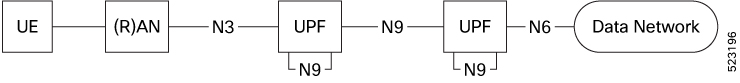
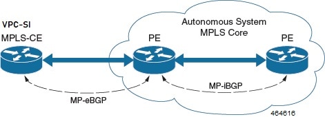
Added MPLS support over the N9 interface.

2023.02.0

Added MPLS support over the N6 interface.

2023.01.0

First introduced.

2022.04.0

Feature Description

Multiprotocol Label Switching (MPLS) is a protocol that uses labels to route packets instead of using IP addresses. UPF supports MPLS to switch MPLS traffic using VPP as the data plane forwarder.

On ASR 5500, the NP4c network processor generates and processes MPLS traffic. On VPC-DI, IFTask generates and processes MPLS traffic.

VPC-SI uses VPP as the data plane forwarder. VPP encapsulates and decapsulates subscriber traffic with MPLS labels. VPP provides support for multiple data plane features that include the MPLS stack as a separate graph node. This feature helps to differentiate between different customer VRFs and support corporate APNs having different addressing models and requirements.

UPF supports MPLS encapsulation over the following interfaces for 5G deployments using VPP:

  • N6—N6 is the interface between UPF and data network (DN).

  • N9—The N9 interface connects two UPFs. It is the interface between Intermediate I-UPF (Visited) and UPF Session Anchor (Home).

The following figure depicts the different interfaces used for MPLS encapsulation in UPF.

Figure 1. MPLS Interfaces

UPF supports the following functionalities for MPLS:

  • Uses VPP MPLS stack to send the MPLS labeled packet.

  • Uses VPP MPLS stack to process the incoming labeled MPLS packet.

  • Uses only MP-BGP as the label distribution protocol.

  • VPPCTL CLI commands display the FTN, FIB, and ILM tables that are in VPP, for debugging and comparing values with boxer configuration.

How it Works

This section briefly describes how the MPLS feature works on UPF.

The VPP forwarder supports all existing functionalities for MPLS packet processing with its own MPLS stack. The VPP MPLS stack is configured with the appropriate FTN (FEC To NHLFE), forwarding information base (FIB) table, and incoming label map (ILM) table. The egress generates the MPLS packet with the correct MPLS header. It also processes the incoming MPLS packet and switches the packet to the appropriate VRF table based on the incoming label.

VPC-SI also supports VPNv6 as described in RFC 4659 – BGP-MPLS IP Virtual Private Network (VPN) Extension for IPv6 VPN.

Deploying UPFs using the N9 Interface

The 5G Core UPF can deploy two UPFs in series through the N9 interface. The N9 interface connects two UPFs between Intermediate I-UPF and UPF Session Anchor. To provide complete mobility with a stable IP anchor across the whole network, the two UPFs are connected depending on the operator network configuration.

Both upstream and downstream traffic between the UPFs is in the form of GTP-U packets. To support MPLS over the N9 interface, the L3 routers present between the two UPFs are capable of advertising BGP routes and labels to the UPFs.

In the upstream direction, I-UPF receives the GTP-U packets from gNodeB and modifies the content of the GTP-U header based on the destination (anchor) UPF. Based on the lookup of the IP header, MPLS encapsulation occurs to encapsulate the GTP-U packet. The MPLS label that needs to be inserted will be received through BGP from the intermediate L3 devices between UPFs. At the anchor UPF, the MPLS header gets decapsulated and transmitted as an IP packet towards the PDN.

In the downstream direction, MPLS encapsulation occurs in the anchor UPF after the IP packet received from PDN is encapsulated by a GTP-U header. This MPLS header is then decapsulated in I-UPF and the corresponding GTP-U packet is then transmitted to gNodeB.

In the following scenarios, UPF moves the N9 interface to a VRF and establishes a VPNv4 or VPNv6 AF BGP neighborship:

  • When the N3 and N9 interfaces share the same physical interface.

  • When the N3 and N9 interfaces are separated.

MPLS-CE Connected to PE

The VPC-SI functions as an MPLS-CE (Customer Edge) network element connected to a Provider Edge (PE) Label Edge Router (LER), which in turn connects to the MPLS core as per RFC 4364.

The following figure illustrates the MPLS-CE to PE connection:

Figure 2. VPC-SI MPLS-CE to PE

The MPLS-CE functions like a PE router within its own Autonomous System (AS). It maintains Virtual Routing and Forwarding (VRF) routes and exchanges VPN route information with the PE through an MP-eBGP (Multi Protocol external BGP) session.

The PE is also configured with VRFs and exchanges VPN routes with other PEs in its AS through MP-iBGP (Multi Protocol internal BGP) connection and MPLS-CE through an MP-eBGP connection.

The EBGP connection allows the PE to change next-hop IP addresses and labels in the routes learnt from IBGP peers before advertising them to the MPLS-CE. The MPLS-CE uses only MP-eBGP to advertise and learn routes. Label Distribution Protocol (LDP) and Resource Reservation Protocol (RSVP) are not required because of direct-connect EBGP peering. The MPLS-CE pushes or pops a single label (learnt over the MP-eBGP connection) to or from the PE.

Sample Configuration

MPLS N6 Configuration

The following is a sample configuration to configure the basic MPLS feature with N6 interface on UPF:

context egress
    ip vrf MPN00001
      ip maximum-routes 100
    #exit
mpls bgp forwarding
router bgp 64455
      neighbor 172.31.35.29 remote-as 65200
      neighbor 172.31.35.29 timers keepalive-interval 60 holdtime-interval 300
      neighbor 172.31.35.29 update-source 172.31.35.4
      neighbor 172.31.35.29 fall-over bfd
      neighbor 172.31.35.29 srp-activated-soft-clear
       address-family ipv4
        redistribute connected
        redistribute static
      #exit
      address-family vpnv4
        neighbor 172.31.35.29 activate
        neighbor 172.31.35.29 send-community extended
      #exit
      address-family vpnv6
        neighbor 172.31.35.29 activate
        neighbor 172.31.35.29 send-community extended
      #exit
      address-family ipv6
        redistribute connected
        redistribute static
      #exit
       ip vrf MPN00001
        route-distinguisher 64455 11100001
        route-target both 64455 11100001
      #exit
      address-family ipv4 vrf MPN00001
        redistribute connected
      #exit
      address-family ipv6 vrf MPN00001
        redistribute connected
      #exit
    interface N6-11
      ip address 172.31.35.4 255.255.255.224
      ip mtu 1504
      bfd interval 999 min_rx 999 multiplier 3
   #exit
    interface N6-12
      ip address 172.31.35.35 255.255.255.224
      ip mtu 1504
      bfd interval 999 min_rx 999 multiplier 3
    #exit
    interface loop_MPN00001 loopback
      ip vrf forwarding MPN00001
      ip address 2.2.4.2 255.255.255.255
    #exit

MPLS N9 Configuration

The following is a sample configuration to configure the MPLS feature with N9 interface on UPF:

context SAEGW
   ip vrf mpls-vrf-1
   #exit
   ip vrf mpls-vrf-2
   #exit
   mpls bgp forwarding
      bfd-protocol
      #exit
   ip prefix-list name up seq 15 permit 50.50.41.4/32
   ip prefix-list name up seq 20 permit 50.50.41.5/32
   ip prefix-list name up seq 25 permit 50.50.41.6/32
   ip prefix-list name up seq 40 permit 50.50.41.7/32
   ip prefix-list name n9-up1 seq 50 permit 60.60.41.5/32
   ip prefix-list name n9-up1 seq 55 permit 60.60.41.6/32
   route-map up_routes1 permit 10
      match ip address prefix-list n9-up1
      #exit
   route-map up_routes permit 10
      match ip address prefix-list up
      #exit
   ip vrf mpls-vrf-1
   route-distinguisher 61601 11100001
   route-target export 61601 11100001
   route-target import 61606 11100001
   route-target import 65200 11100001
   #exit
   address-family ipv4 vrf mpls-vrf-1
      redistribute connected
      redistribute static
      #exit
   address-family ipv6 vrf mpls-vrf-1
      redistribute connected
      redistribute static
      #exit
   ip vrf mpls-vrf-2
   route-distinguisher 61601 11100002
   route-target export 61601 11100002
   route-target import 61606 11100002
   route-target import 65200 11100002
   #exit
   address-family ipv4 vrf mpls-vrf-2
      redistribute connected
      redistribute static
      #exit
   address-family ipv6 vrf mpls-vrf-2
      redistribute connected
      redistribute static
      #exit
    #exit
   interface gn-mpls-n9-ingress
      ip address 172.31.40.5 255.255.255.224
      ip mtu 1504
      bfd interval 999 min_rx 999 multiplier 3
      #exit
   interface n9-ingress-hupf loopback
      ip vrf forwarding mpls-vrf-1
      ip address 60.60.41.5 255.255.255.255
      #exit
   user-plane-service user_plane_svc
      associate gtpu-service pgw-gtpu upf-ingress
      associate gtpu-service n9-ingress upf-ingress interface-type n9
      associate gtpu-service sgw-gtpu-ingress-phazr sgw-ingress
      associate gtpu-service sgw-gtpu-egress sgw-egress
      associate gtpu-service SxC cp-tunnel
      associate sx-service sx-svc
      associate fast-path service
      associate control-plane-group SAEGW
      associate userplane-load-control-profile LCP
      associate userplane-overload-control-profile OLCP
      #exit

VPN-related CLI Commands

UPF supports the VPN-related features and functions across several CLI command modes. The following tables identify commands associated with configuration and monitoring of VPN-related functions.

Table 2. VPN-Related Configuration Commands
CLI Mode Command Description

BGP Address-Family (IPv4/IPv6) Configuration Mode

neighbor ip_address activate

Enables the exchange of routing information with a peer router.

BGP Address-Family (IPv4/IPv6) Configuration Mode

neighbor ip_address send community { both | extended | standard }

Sends the community attributes to a peer router (neighbor).

BGP Address-Family (IPv4/IPv6) Configuration Mode

redistribute connected

Redistributes routes into BGP from another protocol as BGP neighbors.

BGP Address-Family (VPNv4) Configuration Mode

neighbor ip_address activate

Enables the exchange of routing information with a peer router.

BGP Address-Family (VPNv4) Configuration Mode

neighbor ip_address send community { both | extended | standard }

Sends the extended-community attribute to a peer router. In VPN, route-distinguisher and route-target are encoded in the BGP extended-community. This command sends BGP routes with the extended community to a neighbor.

BGP Address-Family (VRF) Configuration Mode

neighbor ip_address activate

Enables the exchange of routing information with a peer router.

BGP Address-Family (VRF) Configuration Mode

neighbor ip_address send community { both | extended | standard }

Sends the extended-community attribute to a peer router. In VPN, route-distinguisher and route-target are encoded in the BGP extended-community. This command sends BGP routes with the extended community to a neighbor.

BGP Address-Family (VRF) Configuration Mode

redistribute connected

Redistributes routes into BGP from another protocol as BGP neighbors.

BGP Configuration Mode

address-family { ipv4 vrf vrf_name | vpnv4 }

Enables the exchange of IPv4 VRF routing information. There is a different mode for each address-family.

BGP Configuration Mode

address-family { ipv6 vrf vrf_name | vpnv6 }

Configures a VPNv6 address family and IPv6 VRF routing in BGP.

BGP Configuration Mode

ip vrf vrf_name

Adds a VRF to BGP and switches to the VRF Configuration mode to allow configuration of BGP attributes for the VRF.

BGP IP VRF Configuration Mode

route-distinguisher { as_value | ip_address } rd_value

Assigns a Route Distinguisher (RD) for the VRF. The RD value must be a unique value on the router for each VRF.

BGP IP VRF Configuration Mode

route-target { both | import | export } { as_value | ip_address } rd_value

Adds a list of import and export route-target extended communities to the VRF.

Context Configuration Mode

ip pool pool_name addr_range vrf vrf_name [ mpls-label input inlabel1 output outlabel1 outlabel2 ]

Configures a pool into the specified VRF. Specify this command with the Next-Hop parameter. inlabel1 is the MPLS label that identifies inbound traffic destined for this pool. outlabel1 and outlabel2 specify the MPLS labels to be added to packets sent for subscribers from this pool.

Context Configuration Mode

ip vrf vrf_name

Creates a VRF and assigns a VRF-ID. A VRF is created in the router.

Context Configuration Mode

ipv6 pool pool_name vrf vrf_name

Associates the pool with that VRF.

Note: By default the configured IPv6 pool is associated with the global routing domain.

Context Configuration Mode

mpls bgp forwarding

Globally enables MPLS Border Gateway Protocol (BGP) forwarding.

Context Configuration Mode

mpls exp value

Sets the default behavior as Best Effort using a zero value in the 3-bit MPLS EXP header. This value applies to all the VRFs in the context. The default behavior is to copy the DSCP value of mobile subscriber traffic to the EXP header, if there is no explicit configuration for DSCP to EXP (via the mpls map-dscp-to-exp dscp n exp m command).

mpls exp disables the default behavior and sets the EXP value to the configured value.

Context Configuration Mode

mpls ip

Globally enables the MPLS forwarding of IPv4 packets along normally routed paths.

Context Configuration Mode

radius change-authorize-nas-ip ip_address { encrypted | key } value port port_num mpls input inlabel output outlabel1 outlabel2

Configures COA traffic to use the specified MPLS labels. inlabel identifies the inbound COA traffic. outlabel1 and outlabel2 specify the MPLS labels to add to the COA response. outlabel1 is the inner output label and outlabel2 is the outer output label.

Ethernet Interface Configuration Mode

mpls ip

Enables dynamic MPLS forwarding of IP packets on this interface.

Exec Mode

clear ip bgp peer

Clears BGP sessions.

Table 3. VPN-Related Monitoring Commands
CLI Mode Command Description

Exec Mode show Commands

show ip bgp neighbors

Displays information regarding BGP neighbors.

Exec Mode show Commands

show ip bgp vpnv4 { all | route-distinguisher | vrf }

Displays all VPNv4 routing data, routing data for a VRF or a route-distinguisher.

Exec Mode show Commands

show ip bgp vpnv6

Displays contents of VPNv6 routing table.

Exec Mode show Commands

show ip bgp vpnv6 { all | route-distinguisher | vrf }

Displays all VPNv6 routing data, routing data for a VRF or a route-distinguisher.

Exec Mode show Commands

show ip fib table-id table_id

Displays information for FIB table.

Exec Mode show Commands

show ip pool

Displays pool details including the configured VRF.

Exec Mode show Commands

show mpls cross-connect

Displays MPLS cross-connect information. MPLS tunnel cross-connects between interfaces and Label-Switched Paths (LSPs). LSP connects two distant interface circuits of the same type through MPLS tunnels.

Exec Mode show Commands

show mpls fib table table_id

Displays MPLS forwarding information base (FIB) table information.

Exec Mode show Commands

show mpls ftn [ vrf vrf_name ]

Displays MPLS FEC-to-NHLFE (FTN) table information.

Exec Mode show Commands

show mpls ftn [ vrf vrf_name ]

Displays the contents of the MPLS FTN table for a specified VRF.

Exec Mode show Commands

show mpls ilm [ all | label label_value ]

Displays MPLS Incoming Label Map (ILM) table information.

Exec Mode show Commands

show mpls nexthop-label-forwarding-entry

Displays MPLS Next-Hop Label Forwarding Entry (NHLFE) table information.

Monitoring and Troubleshooting

This section provides information regarding the CLI command to monitor and troubleshoot the feature.

Show Commands and Outputs

This section provides information regarding show commands and their outputs in support of this feature.

show mpls ftn vpp

The output of this command contains the "vpp" field that displays the configured VPP dataplane values in the VPP dataplane forwarder. Use this command for debugging purposes.

  • vpp

    • all-vrf

    • summary

    • vrf