Home Routed Roaming Support

Feature Summary

Summary Data

Table 1. Summary Data

Applicable Product(s) or Functional Area

5G-UPF

Applicable Platform(s)

VPC-SI

Feature Default Setting

Enabled – Always-on

Related Changes in this Release

Not Applicable

Related Documentation

Not Applicable

Revision History

Table 2. Revision History
Revision Details Release

UPF supports the following functionalities in the roaming status feature: 2023.02.0

• Source Interface Type IE to indicate the 3GPP Interface Type

• Subscriber Params IE to indicate the Roaming Status

2023.02.0

First introduced

2021.02.0

Feature Description

The mobile network operators form roaming partnerships to provide seamless services to their subscribers in geographies beyond their network reach. Operator network boundaries are designated by public land mobile networks (PLMN). The home network for a subscriber is called an HPLMN and the visited network, which renders the mobile service is termed as the VPLMN.

The VPLMN provides access network services and packet routing to the packet core, whereas the HPLMN provides data network access to the subscriber. This feature enables the UPF to support the flavor of routing that is termed as the Home Routed (HR) roaming.

Visited UPF (vUPF) supports the following functionalities:

  • Handle the dummy PDRs with associated FAR action as buffer

  • Buffer the incoming packets before rule matching

  • Handle the QoS and FAR updates from the SMF for debuffering of packets

  • Send the buffered packets after matching with the PDR

  • Send vUPF traffic over Fast Path

  • Send N9 interface GTP-U tunnel

  • LI support

  • MonSub CLI command and PCAP file support

vUPF and Home UPF (hUPF) support the following functionalities:

  • QoS flow Based Charging (QBC) on the UPF

  • Source Interface Type IE in PDR indicates the 3GPP Interface Type in UPF

  • Selection of the GTP-U service by receiving 3GPP Interface Type received in PDI IE of create PDR.

  • Subscriber Params IE indicates the roaming status in UPF

Relationships

The roaming status functionality relates to the UPF Ingress Interfaces feature that indicates the following types of roaming:

  • Homer

  • Roamer

  • Visited LBO

  • Visited HR

The UPF supports different GTP-U ingress interfaces. It allows a separate network for the N3 interface and N9, S5u, and S8u interfaces.

The GTP-U ingress interfaces to handle roaming and outbound calls include:

  • N3—N3 is the interface between gNodeB and UPF. To handle 5G home calls, the N3 interface must be a private IP address.

  • N9—The N9 interface connects two UPFs. It is the interface between intermediate I-UPF and UPF session anchor connecting different PLMN. To handle 5G outbound roaming calls, the N9 interface must be a public IP address.

  • S5u—S5u is similar to the N9 interface that connects two UPFs. The interface connects the intermediate I-UPF and UPF session anchor. To handle 4G inbound calls, the S5u is set to a public IP since the SGW-U is public for enabling the S-GW.

  • S8u—S8u is an inter-PLMN variant of the S5u interface. To handle 4G outbound roaming calls, the S8u interface must be a public IP address.

For more information, refer to the UPF Ingress Interfaces chapter.

Architecture

This section describes the architecture for the home routing roaming support feature.

Bufffering and Debuffering on the vUPF

The buffering and debuffering procedure on the vUPF for the UPF HR roaming, are as follows:

  1. Two dummy PDRs (UL or DL) is created initially at vUPF by vSMF with default value as QFI and the buffering as an FAR action.

  2. The packets coming from the N3 and N9 interfaces get buffered based on the FAR action before doing a packet classification and application of policy.

  3. If buffered packet count exceeds the configured limits then the subsequent packets are dropped.

  4. The buffered packets are sent for classification and policy application after the update FAR is received with action as forward and updated TEID in modify request from vSMF.

  5. The vSMF initiates the removal of default QER and URR while sending the update FAR with action forward and sends a new PDR with the required QER and URR.

  6. The packets are sent on the required interface that is based on the QFI defined in the new QER.

  7. If there is no matching PDR with TEID and QFI installed then the debuffered packets is dropped.

Charging — Predef and Dynamic Rules on the hUPF

The charging predef and dynamic rules on the hUPF, are as follows:

  1. The SMF associates FBC URRs + QBC URRs + Session URRs with dynamic PDRs.

  2. The SMF associates QBC URRs + Session URRs with predef PDRs.

  3. The UPF associates the URRs created by installed global PDRs to the received predef PDRs QBC URRs + Sess URRs.

  4. The QBC URRs have no Linked URRs.

  5. The QBC URRs include no FBC URRs or Session URRs usage reporting.

  6. The UPF links the Session URRs to FBC URRs as Linked URRs.

  7. The Session URRs include FBC URRs and QBC URRs usage reporting.

  8. The UPF relies on the SMF for the update or removal of each of the QBC and Sess URRs.

Charging — Static Rules on the hUPF

The charging static rules on the hUPF, are as follows:

  1. The SMF associates FBC URRs + QBC URRs + Session URRs with RB PDRs.

  2. The UPF associates the URRs created by installed global PDRs to the received RB PDRs QBC URRs + Sess URRs.

  3. The UPF does not link QBC URRs with any URRs.

  4. The UPF links the static FBC URRs with the Session URRs.

  5. The UPF links the Session URRs to the FBC URRs as linked URRs for usage reporting.

  6. The UPF relies on the SMF for the update or removal of each of the QBC and the SMF URRs.

How it Works

This section provides details about the PDU session create, modify, and release procedures for the HR roaming feature in the UPF.

PDU Session Establishment Procedure

This section provides details about the create PDU session procedure for the UPF.

Figure 1. PDU Session Establishment Call Flow
Table 3. PDU Session Establishment Call Flow Description

Step

Description

1

The UE initiates a PDU Session Establishment Request to the AMF.

2

The AMF selects an SMF.

3a

The AMF invokes the Nsmf_PDUSession_CreateSMContext Request and sends it to the vSMF.

3b

The vSMF sends a Nsmf_PDUSession_CreateSMContext Response to the AMF.

4

The vSMF selects a UPF in VPLMN.

5a

The vSMF sends an N4 Session Establishment Request with dummy PDRs, FARs, QERs, or URRs to the vUPF. In this request, the vSMF informs the vUPF to allocate the CN Tunnel information for the N3 and N9 interfaces. The vSMF sends Source Interface Type IE in Access PDR as N3 3GPP Access (11), and in Core PDR as N9 (21) for roaming.

5b

The vUPF creates the N3 and N9 CN tunnel information and acknowledges by sending this information in an N4 Session Establishment Response.

6

The vSMF sends an Nsmf_PDUSession_Create Request to the hSMF.

7

The hSMF registers with the UDM for a given PDU session.

8

The SMF performs a secondary authorization or authentication during the establishment of the PDU session by a DN-AAA server.

9a

The hSMF selects the PCF.

9b

The SMF performs an SM Policy Association Establishment procedure to establish an SM Policy Association with the PCF and get the default PCC rules for the PDU session.

10

The hSMF selects the UPF.

11

The hSMF initiates an SM Policy Association Modification procedure.

12a

The hSMF initiates an N4 Session Establishment procedure with the selected UPF. The N9 CN tunnel information from the vUPF is transferred to hUPF in FAR. The hSMF sends Source Interface Type in Access PDR as N9(21) or S5u interface for roaming depending on the RAT where it registers the call.

12b

The UPF acknowledges by sending an N4 Session Establishment Response. The hUPF provides the N9 CN tunnel information to the vUPF.

12c

The downlink path is established between the hUPF and vUPF and data packets are sent to the vUPF where it gets buffered.

13

The hSMF sends an Nsmf_PDUSession_Create Response message to the vSMF.

14

The vSMF sends an Namf_Communication_N1N2MessageTransfer message to the AMF.

15

The AMF sends the NAS message containing PDU Session ID and PDU Session Establishment Accept targeted to the UE and the N2 SM information received from the SMF within the N2 PDU Session Request to the RAN.

16

The RAN issues AN specific signalling exchange with the UE that is related with the information received from SMF.

17

The RAN sends an N2 PDU Session Response message to the AMF.

18

The AMF sends the Nsmf_PDUSession_UpdateSMContext Request message to the vSMF. The AMF forwards the N2 SM information received from RAN to the vSMF.

19a

The vSMF initiates an N4 Session Modification procedure with the vUPF. The vSMF provides packet detection, enforcement, and reporting rules to be installed on the vUPF for this PDU session, including AN Tunnel Information, H-CN Tunnel Information and V-CN Tunnel Information.

19b

The vUPF provides an N4 Session Modification Response to the vSMF. After this step, the vUPF delivers any down-link packets to the UE that might have been buffered for this PDU Session.

20

The vSMF sends an Nsmf_PDUSession_UpdateSMContext Response message to the AMF.

21

The vSMF sends an Nsmf_PDUSession_SMContextStatusNotify message to the AMF.

22

If it's a PDU session of type IPv6 or IPv4v6, the hSMF generates an IPv6 Router Advertisement and sends it to the UE through the N4 interface, hUPF, and vUPF.

23

If the vSMF received in step 18 is an indication that the RAN has rejected some QFIs the vSMF notifies the hSMF through an Nsmf_PDUSession_Update Request. The hSMF is responsible for updating the QoS rules and QoS Flow level QoS parameters for the QoS Flow(s) associated with the QoS rule(s) in the UE accordingly.

24

If the PDU Session establishment failed after step 4, the hSMF performs the following steps:

  • If the SMF is no more handling a PDU Session of the UE for this (DNN, S-NSSAI), the hSMF unsubscribes to the modifications of Session Management Subscription data for the corresponding (SUPI, DNN, S-NSSAI), by using Nudm_SDM_Unsubscribe.

  • The hSMF deregisters for the given PDU Session by using Nudm_UECM_Deregistration (SUPI, DNN, PDU Session ID).

PDU Session Modification Procedure

This section provides details about the modify PDU session procedure for the UPF.

Figure 2. PDU Session Modification Call Flow
Table 4. PDU Session Modification Call Flow Description

Step

Description

1a
  • The UE initiates the PDU Session Modification procedure by the transmission of an NAS message to the AMF.

  • The AMF initiates the Nsmf_PDUSession_UpdateSMContext message.

  • The vSMF sends an Nsmf_PDUSession_Update Request message to the hSMF.

  • The hSMF acknowledges and sends an Nsmf_PDUSession_Update Response message to the vSMF.

1b

The PCF performs a PCF initiated SM Policy Association Modification procedure to notify SMF about the modification of policies.

1c

The UDM updates the subscription data of hSMF by Nudm_SDM_Notification (SUPI, Session Management Subscription Data). The hSMF updates the Session Management Subscription Data and acknowledges the UDM by returning an Ack with (SUPI).

1d

The SMF might modify the PDU session. This procedure can also be triggered based on locally configured policy or triggered from the RAN.

1e

RAN indicates to the SMF when the AN resources onto which a QoS Flow is mapped are released irrespective of whether notification control is configured. RAN sends the N2 message to the AMF. The AMF invokes Nsmf_PDUSession_UpdateSMContext procedure.

The vSMF sends an Nsmf_PDUSession_Update Request message to the hSMF.

The hSMF acknowledges and sends an Nsmf_PDUSession_Update Response message to the vSMF.

2

The SMF reports some subscribed event to the PCF by performing an SMF initiated SM Policy Association Modification procedure.

3

The hSMF invokes the Nsmf_PDUSession_Update Request service operation to the vSMF.

3a

The hSMF initiates an N4 Session Modification procedure with the selected hUPF.

3b

The hUPF acknowledges and sends an N4 Session Modification Response message to the hSMF.

4a

The vSMF sends an Nsmf_PDUSession_UpdateSMContext Response message to the AMF.

4b

The vSMF sends an Nsmf_PDUSession_SMContextStatusNotify message to the AMF.

5

The AMF sends the NAS message containing PDU Session ID and PDU Session Establishment Accept targeted to the UE and the N2 SM information received from the SMF within the N2 PDU Session Request to the RAN.

6

The RAN issues AN specific signalling exchange with the UE that is related with the information received from SMF.

7

The AMF sends the Nsmf_PDUSession_UpdateSMContext Request message to the vSMF. The AMF forwards the N2 SM information received from RAN to the vSMF.

8

The AMF sends the Nsmf_PDUSession_UpdateSMContext Request message to the vSMF. The AMF forwards the N2 SM information received from RAN to the vSMF.

9a

The vSMF initiates an N4 Session Modification procedure with the vUPF. The vSMF provides packet detection, enforcement, and reporting rules to be installed on the vUPF for this PDU session, including AN Tunnel Information, H-CN Tunnel Information and V-CN Tunnel Information.

9b

The vUPF provides an N4 Session Modification Response to the vSMF. After this step, the vUPF delivers any down-link packets to the UE that might have been buffered for this PDU Session.

10

The vSMF sends an Nsmf_PDUSession_UpdateSMContext Response message to the AMF.

11

The UE sends a PDU Session Modification Command Ack message to the RAN.

12

The RAN initiates an N2 NAS Uplink Transfer with the AMF.

13

The vSMF sends an Nsmf_PDUSession_UpdateSMContext Response message to the AMF.

14

The vSMF sends an Nsmf_PDUSession_SMContextStatusNotify message to the AMF.

15

The vSMF responds to the hSMF with an Nsmf_PDUSession_Update response carrying the information like PCO provided by the UE in the SM PDU Session Modification Command Ack message from the UE to the vSMF. The hSMF modifies the PDU session context.

16a

The vSMF initiates an N4 Session Modification procedure with the vUPF. The vSMF provides packet detection, enforcement, and reporting rules to be installed on the vUPF for this PDU session, including AN Tunnel Information, H-CN Tunnel Information and V-CN Tunnel Information.

16b

The vUPF provides an N4 Session Modification Response to the vSMF. After this step, the vUPF delivers any down-link packets to the UE that might have been buffered for this PDU Session.

17

The hSMF initiates an SM Policy Association Modification procedure.

PDU Session Release Procedure

This section provides details about the PDU session release procedure for the UPF.

Figure 3. PDU Session Release Call Flow
Table 5. PDU Session Release Call Flow Description

Step

Description

1a
  • The UE initiates the UE Requested PDU Session Release procedure by the transmission of an NAS message to the AMF.

  • The AMF invokes the Nsmf_PDUSession_UpdateSMContext service operation and provides the N1 SM container to the SMF together with User Location Information (ULI) received from the RAN.

  • The vSMF initiates N4 Session Modification to instruct the vUPF to stop forwarding uplink traffic.

  • The vSMF invokes the Nsmf_PDUSession_Update Request service operation to request the hSMF to release the PDU Session. The hSMF responds to the request immediately.

1b

  • The AMF invokes the Nsmf_PDUSession_ReleaseSMContext service operation to request the release of the PDU Session.

  • The vSMF initiates N4 Session Modification to instruct the vUPF to stop forwarding uplink traffic.

  • The vSMF initiates the release of the PDU Session at the hSMF by invoking the Nsmf_PDUSession_Release request.

1c
  • The PCF invokes an SM Policy Association Termination procedure to request the release of the PDU Session.

  • The hSMF initiates N4 Session Modification to instruct the hUPF to stop forwarding downlink traffic.

1d
  • RAN indicates to the vSMF that the PDU Session-related resource is released when all the QoS Flow(s) of the PDU Session are released.

  • The vSMF initiates N4 Session Modification to instruct the vUPF to stop forwarding uplink traffic.

  • The vSMF initiates the Nsmf_PDUSession_Update Request toward the hSMF and the hSMF acknowledges with a response.

1e

The SMF decides to release a PDU session. The hSMF initiates N4 Session Modification to instruct the hUPF to stop forwarding downlink traffic.

1f

The AMF invokes the Nsmf_PDUSession_UpdateSMContext service operation with a release indication to request the release of the PDU session.

The vSMF initiates N4 Session Modification to instruct the vUPF to stop forwarding uplink traffic. The vSMF invokes the Nsmf_PDUSession_Update Request toward the hSMF.

2a

The hSMF sends an N4 Session Release Request (N4 Session ID) message to the hUPFs of the PDU session. The hUPFs drop any remaining packets of the PDU session and release all tunnel resource and contexts associated with the N4 Session.

2b

The hUPF(s) acknowledges the N4 Session Release Request by the transmission of an N4 Session Release Response message to the hSMF.

3a

The SMF responds to the AMF with the Nsmf_PDUSession_UpdateSMContext response.

4a

The vSMF sends an N4 Session Release request to the vUPF.

4b

The vUPF acknowledges and sends an N4 Session Release response to the hSMF.

5a

The vSMF sends an Nsmf_PDUSession_ReleaseSMContext Response message to the AMF.

5b

The vSMF sends an Nsmf_PDUSession_UpdateSMContext Response message to the AMF.

5c

The N1N2 Message Transfer procedure occurs between the AMF and vSMF.

6

The hSMF includes the N2 SM Resource Release request in the message sent to the AMF, then the AMF transmits the NAS message to the UE.

7

When the RAN receives an N2 SM request to release the AN resources associated with the PDU session, it issues AN specific signalling exchanges with the UE to release the corresponding AN resources.

8

If the RAN receives an N2 SM request to release the AN resources, it acknowledges the N2 SM Resource Release Request by sending an N2 SM Resource Release Ack message to the AMF.

9

The AMF sends an Nsmf_PDUSession_UpdateSMContext Response message to the vSMF.

10

The vSMF responds to the AMF with an Nsmf_PDUSession_UpdateSMContext response.

11

The UE acknowledges the PDU Session Release Command by sending a NAS message over the RAN.

12

The AMF invokes the Nsmf_PDUSession_UpdateSMContext to the vSMF.

13

The SMF responds to the AMF with an Nsmf_PDUSession_UpdateSMContext response.

14

The vSMF responds to the hSMF with an Nsmf_PDUSession_Update Request invoked at step 3a and confirms the PDU session release.

15

The vSMF initiates an N4 Session Modification procedure with the vUPF. The vSMF provides packet detection, enforcement, and reporting rules to be installed on the vUPF for this PDU session, including AN Tunnel Information, H-CN Tunnel Information and V-CN Tunnel Information.

15a

The hSMF releases the SM policy control association with the PCF by invoking the SM Policy Association Termination procedure.

15b - 15c

In case the PDU Session Release is HPLMN-initiated, the hSMF releases the corresponding User Plane resources.

15d

The hSMF invokes the Nudm_UECM_Deregistration service operation.

16a

The hSMF requests the vSMF to release all contexts associated with the PDU session by invoking the Nsmf_PDUSession_StatusNotify (Release) operation.

16b

The vSMF requests the AMF to release all contexts associated with the PDU Session by invoking the Nsmf_PDUSession_SMContexStatusNotify (Release). The AMF releases the association between the vSMF ID and the PDU Session ID.

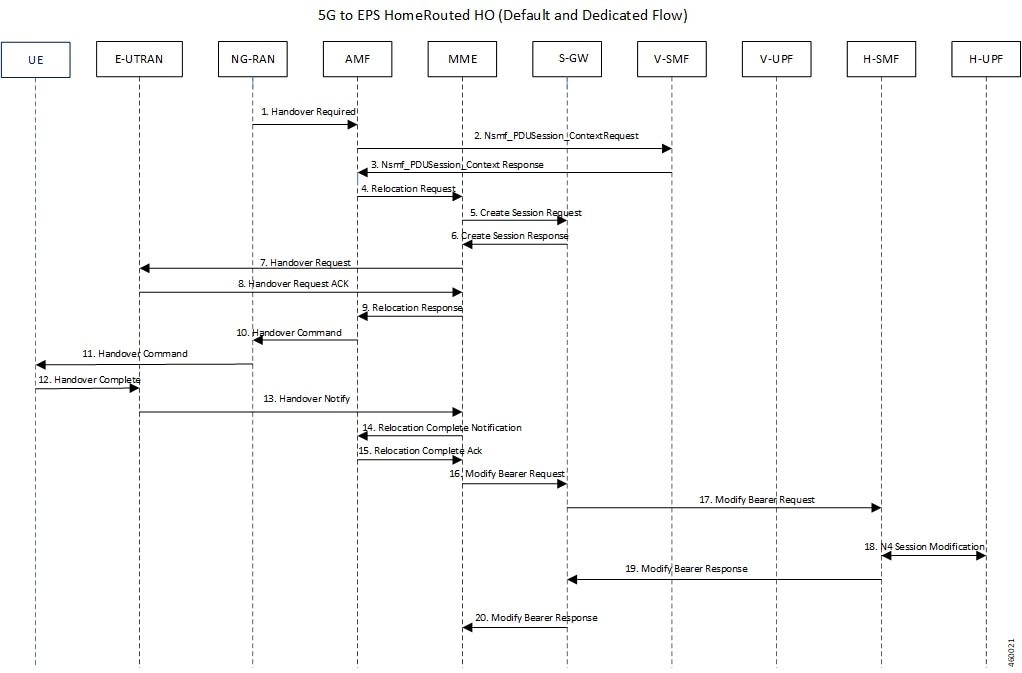
5G to 4G Handover

This section provides details about the 5G to 4G handover.

Figure 4. 5G to 4G Handover Call Flow
Table 6. 5G to 4G Handover Call Flow Description

Step

Description

1

After the 5G session is established, the NG-RAN initiates the handover process by sending the Handover Required message to the AMF.

2

The AMF invokes the Nsmf_PDUSession_Context Request and sends it to the vSMF.

3

The vSMF sends a Nsmf_PDUSession_Context Response to the AMF.

4

The AMF sends a Relocation Request to the MME.

5

The MME sends Create Session Request to the S-GW.

6

The S-GW sends a Create Session Response message back to the MME.

7

The MME sends a Handover Request message to E-UTRAN.

8

The E-UTRAN acknowledges and sends a Handover Request ACK message back to the MME.

9

The MME sends the Relocation Response message to the AMF.

10

The AMF sends a Handover Command message to the NG-RAN.

11

The NG-RAN commands the UE to handover to the target access network by sending the Handover Command.

12

The UE responds to the E-UTRAN with a Handover Complete message, and the uplink data path is established.

13

The E-UTRAN notifies the MME that the UE is handed over to the NG-RAN.

14

The MME sends a Relocation Complete Notification message to the AMF.

15

The AMF acknowledges and sends a Relocation Complete Ack message to the MME.

16

The MME sends a Modify Bearer Request message to the S-GW.

17

The S-GW forwards the Modify Bearer Request message to the hSMF.

18

The hSMF initiates an N4 Session Modification procedure with the hUPF.

19

The hSMF responds to the S-GW with a Modify Bearer Response message, and the downlink data path is established.

20

The S-GW sends the Modify Bearer Response message to the MME.

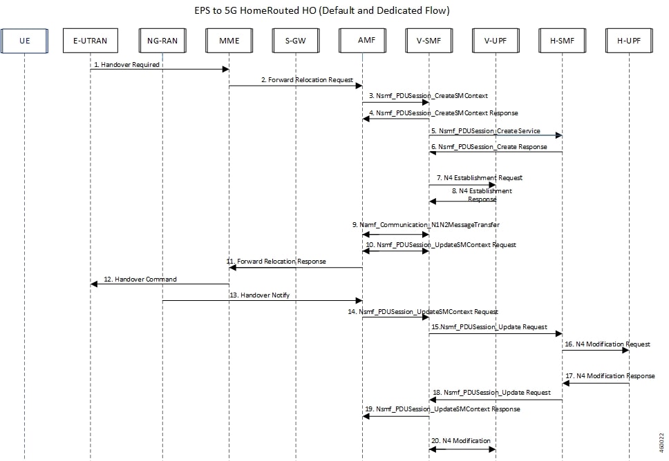
4G to 5G Handover

This section provides details about the 4G to 5G handover.

Figure 5. 4G to 5G Handover Call Flow
Table 7. 4G to 5G Handover Call Flow Description

Steps

Description

1

After the 4G session is established, the E-UTRAN initiates the handover process by sending the Handover Required message to the MME.

2

The MME sends a Forward Relocation Request to the AMF.

3

The AMF invokes the Nsmf_PDUSession_CreateSMContext Request and sends it to the vSMF.

4

The vSMF sends a Nsmf_PDUSession_CreateSMContext Response to the AMF.

5

The vSMF sends a Nsmf_PDUSession_Create Service message to create a new PDU Session in the hSMF.

6

The hSMF responds with a Nsmf_PDUSession_Create Response message.

7

The vSMF sends an N4 Establishment Request to the vUPF.

8

The vUPF acknowledges by sending an N4 Establishment Response.

9

The vSMF sends an Namf_Communication_N1N2MessageTransfer message to the AMF.

10

The AMF sends the Nsmf_PDUSession_UpdateSMContext Request message to the vSMF.

11

The AMF sends a Forward Relocation Response message to the MME.

12

The MME sends the Handover Command to the E-UTRAN.

13

The NG-RAN notifies the AMF that the UE is handed over to the NG-RAN.

14

The AMF sends the Nsmf_PDUSession_UpdateSMContext Request message to the vSMF.

15

The vSMF initiates the Nsmf_PDUSession_Update Request toward the hSMF.

16

The hSMF sends an N4 Modification Request with PDRs, FARs, QERs, or URRs to the hUPF.

17

The hUPF responds with an N4 Modification Response message.

18

The hSMF invokes the Nsmf_PDUSession_Update Request service operation to the vSMF.

19

The vSMF sends an Nsmf_PDUSession_UpdateSMContext Response message to the AMF.

20

The vSMF initiates an N4 Modification procedure with the vUPF.


Note


To support the roaming status functionality, the Roaming Status IE is sent in subscriber params during the session establishment or in the Hand Over.


Standards Compliance

The HR roaming support feature complies with the following standards:

  • 3GPP TS 23.502 "Procedures for the 5G System"

  • 3GPP TS 29.061 "Interworking between the Public Land Mobile Network (PLMN) supporting packet based services and Packet Data Networks (PDN)"

  • 3GPP TS 29.244 16.5.0 "Interface between the Control Plane and the User Plane nodes"

Limitations

The HR roaming support feature has the following limitations:

  • Router Advertisement (RA) or Router Solicitation (RS) packets are charged and counted in default QFI PDR on the vUPF.

  • No support for QER enforcement policing on the vUPF.

  • No support for LI on the vUPF.

Configuring the HR Roaming Support for UPF

This section describes how to configure the HR roaming support feature for UPF.

Configure Buffering Support of Visitors Calls on vUPF

To configure the buffering support of visitors calls on the vUPF, use the following CLI commands:

config 
   user-plane [converged mode | buffered-packet-count [ instance-limit instance_limit_value { session-limit session_limit_value} | { session-limit session_limit_value { instance-limit instance_limit_value} ] ] 
   exit 

NOTES:

  • buffering-packet-count : Configure max session and instance limit for buffering the packets.

  • instance-limit instance_limit_value : Configures maximum number of packets to buffer for all session per SessMgr instance. The default range is 1 to 10000.

  • session-limit session_limit_value : Configures maximum number of packets to buffer per session. The default range is 1 to 255.

Verify the Buffering Support of Visitors Calls on vUPF

To verify the support of buffering limit for traffic on visitor calls on the vUPF, use the show configuration CLI command.

The following code is a sample output of the CLI command.

[local]qvpc-si# show configuration
...
...
    #exit
  user-plane buffered-packet-count session-limit 5 instance-limit 10
  context ingress
…
…

Configure the GTP-U Service and N9 Interface Association

To configure the association of GTP-U Service and N9 Interface, use the following CLI commands:

config 
   context ingress 
      user-plane-service user-plane-service 
              associate gtpu-service service_name [ cp-tunnel | pgw-ingress | sgw-egress | sgw-ingress | upf-egress | upf-ingress | interface-type [ n9 | s5u | s8u | n3 ]] 
              no associate gtpu-service upf-egress 
      exit 
   exit 
exit 

NOTES:

  • upf-egress : Configure the interface type as UPF egress used for N9 interface.

  • interface-type [ n9 | s5u | s8u | n3 ] : Configure the desired GTP-U ingress interface type.

  • no associate gtpu-service upf-egress : Configure to remove the GTP-U service and N9 interface association.

Verify the GTP-U Service and N9 Interface Association

To verify the association of GTP-U Service and N9 Interface, use the show user-plane-service all CLI command.

The following code is a sample output of the CLI command.

[local]qvpc-si# show user-plane-service all

Service name                        : user-plane-service
  Service-Id                        : 6
  Context                           : ingress
  Status                            : STARTED
  UPF Ingress GTPU Service          : sx-gtpu-service
  UPF Egress GTPU Service           : sx-upf_egress_gtpu
  SGW Ingress GTPU Service          : sx-sgw_ingress_gtpu
  SGW Egress GTPU Service           : sx-sgw_egress_gtpu
….
[local]qvpc-si# show configuration context ingress
config
  context ingress
....
...
   user-plane-service user-plane-service
      associate gtpu-service sx-gtpu-service upf-ingress
      associate gtpu-service sx-upf_egress_gtpu upf-egress
      associate gtpu-service sx-sgw_ingress_gtpu sgw-ingress
      associate gtpu-service sx-sgw_egress_gtpu sgw-egress
      associate gtpu-service up-gtpu cp-tunnel
      associate sx-service sxu
      associate control-plane-group g1
    exit
...

Roaming Status in Sub-Params IE

The following is an example of the Sub-Params IE that displays the roaming status:

SUBSCRIBER PARAMS:
Type: 226
Rat-Type: 3
SGSN-Address: 20.20.20.17
ULI: ECGI=216354001234c800
GGSN-Address: 20.20.20.3
Roaming-Status: Homer/Roamer/Visitor-hr/Visitor-LBO

Source Interface Type IE

The Source Interface Type IE indicates the 3GPP interface type of the source interface.

The 3GPP Interface Type IE indicates the 3GPP interface type of the source interface within the PDR IE, or the 3GPP interface type of the Destination Interface within the FAR IE.

The following is an example of Create PDR that displays Source Interface Type:

CREATE PDR:
    Type: 1
    Value:
PDR ID:
    Type: 56
    Value:
        RULE ID: 0x0002
PRECEDENCE:
    Type: 29
    Value: 0x00000001

PDI:
Type: 2
Value:
SOURCE INTERFACE:
    Type: 20
    Value: CORE (1)
Traffic Endpoint ID:
    Type: 131
    Value: 0x0001
SOURCE INTERFACE TYPE:  
    Type: 160
    Value: N9 (0x0F)
FAR ID:
    Type: 108
    Value: 0x8002
RULEBASE:
    Type: 207
    Value: 
QER ID:
    Type: 109
    Value: 0x80000001

Monitoring and Troubleshooting

This section provides troubleshooting information for this feature.

show user-plane-service statistics all

To see the statistics for the User Plane service, use the following CLI command:

show user-plane-service statistics all 

The following is a sample output:

PDNs By PLMN-Type:
  Home/Roaming Subscriber PDNs:
    Active:                            0    Setup:                             0
    Released:                       0
 
  Visiting Subscriber PDNs:  
    Active:                            0    Setup:                             0
    Released:                       0

  PDNs Rejected By Reason:

…
…

  Data Statistics Related To Paging:
    Packets Buffered:                  5    Bytes Buffered:                  420
    Packets Discarded:                 1    Bytes Discarded:                  84

  Total Data Statistics:

show subscribers user-plane-only full all

To see all the subscribers using the user plane service, use the following CLI command:

show subscribers user-plane-only full all 

The following is a sample output:

….
Converged Session: No                 Converged Peer Callid:      n/a
  Visited Call: Yes
  Subscriber Parameters:
…..
Interface Type: N4
….
Subscriber Parameters:
IMSI: 123456789012345
…..

Session-ID: 1414146500000001
Roaming Status: Homer

show subscribers user-plane-only callid pdr full all

The show subscribers user-plane-only callid call_id pdr full all command displays all PDR information.

The Source Interface Type field displays the Source Interface Type IE received from SMF.

The following is a sample output of this command:

show subscribers user-plane-only callid call_id pdr full all  
show subscribers user-plane-only callid 0098e4b0 pdr full all
Callid: 0098e4b0
Interface Type: N4
…
Matched Bytes:            0
Matched Packets:          0
Precedence:               0
Source Interface:         Access
Source Interface Type:    N9
…

show user-plane-service gtpu statistics gtpu-service n9-egress

The following is a sample output of this command for visiting UPF:

[local]Test-UPF4# show user-plane-service gtpu statistics gtpu-service n9-egress

Total Data Stats:
Uplink Packets: 10 Uplink Bytes: 2400
Downlink Packets: 10 Downlink Bytes: 2400
Packets Discarded: 0 Bytes Discarded: 0

QoS Stats:

QCI 1:
Uplink Packets: 0 Uplink Bytes: 0
Downlink Packets: 0 Downlink Bytes: 0
Packets Discarded: 0 Bytes Discarded: 0

QCI 2:
Uplink Packets: 8 Uplink Bytes: 1920
Downlink Packets: 8 Downlink Bytes: 1920
Packets Discarded: 0 Bytes Discarded: 0

QCI 3:
Uplink Packets: 0 Uplink Bytes: 0
Downlink Packets: 0 Downlink Bytes: 0
Packets Discarded: 0 Bytes Discarded: 0

QCI 4:
Uplink Packets: 0 Uplink Bytes: 0
Downlink Packets: 0 Downlink Bytes: 0
Packets Discarded: 0 Bytes Discarded: 0

QCI 5:
Uplink Packets: 0 Uplink Bytes: 0
Downlink Packets: 0 Downlink Bytes: 0
Packets Discarded: 0 Bytes Discarded: 0

QCI 6:
Uplink Packets: 0 Uplink Bytes: 0
Downlink Packets: 0 Downlink Bytes: 0
Packets Discarded: 0 Bytes Discarded: 0

QCI 7:
Uplink Packets: 0 Uplink Bytes: 0
Downlink Packets: 0 Downlink Bytes: 0
Packets Discarded: 0 Bytes Discarded: 0

QCI 8:
Uplink Packets: 0 Uplink Bytes: 0
Downlink Packets: 0 Downlink Bytes: 0
Packets Discarded: 0 Bytes Discarded: 0

QCI 9:
Uplink Packets: 2 Uplink Bytes: 480
Downlink Packets: 2 Downlink Bytes: 480
Packets Discarded: 0 Bytes Discarded: 0

QCI 65:
Uplink Packets: 0 Uplink Bytes: 0
Downlink Packets: 0 Downlink Bytes: 0
Packets Discarded: 0 Bytes Discarded: 0

QCI 66:
Uplink Packets: 0 Uplink Bytes: 0
Downlink Packets: 0 Downlink Bytes: 0
Packets Discarded: 0 Bytes Discarded: 0

QCI 69:
Uplink Packets: 0 Uplink Bytes: 0
Downlink Packets: 0 Downlink Bytes: 0
Packets Discarded: 0 Bytes Discarded: 0

QCI 70:
Uplink Packets: 0 Uplink Bytes: 0
Downlink Packets: 0 Downlink Bytes: 0
Packets Discarded: 0 Bytes Discarded: 0

QCI 80:
Uplink Packets: 0 Uplink Bytes: 0
Downlink Packets: 0 Downlink Bytes: 0
Packets Discarded: 0 Bytes Discarded: 0

QCI 82:
Uplink Packets: 0 Uplink Bytes: 0
Downlink Packets: 0 Downlink Bytes: 0
Packets Discarded: 0 Bytes Discarded: 0

QCI 83:
Uplink Packets: 0 Uplink Bytes: 0
Downlink Packets: 0 Downlink Bytes: 0
Packets Discarded: 0 Bytes Discarded: 0

Non-Std QCI(Non-GBR):
Uplink Packets: 0 Uplink Bytes: 0
Downlink Packets: 0 Downlink Bytes: 0
Packets Discarded: 0 Bytes Discarded: 0
Uplink Packets: 0 Uplink Bytes: 0
Downlink Packets: 0 Downlink Bytes: 0
Packets Discarded: 0 Bytes Discarded: 0

Total uplink packets GBR QCI's: 8
Total uplink Bytes GBR QCI's: 1920
Total Downlink packets GBR QCI's: 8
Total Downlink Bytes GBR QCI's: 1920
Total uplink packets Non-GBR QCI's: 2
Total uplink Bytes Non-GBR QCI's: 480
Total Downlink packets Non-GBR QCI's: 2
Total Downlink Bytes Non-GBR QCI's: 480

Path Management Messages:
Echo Request Rx: 29 Echo Response Rx: 10
Echo Request Tx: 10 Echo Response Tx: 29
SuppExtnHdr Tx: 0 SuppExtnHdr Rx: 0

Peer Stats:
Total GTPU Peers: 1
Total GTPU Peers with Stats: 1

Tunnel Management Messages:
Error Indication Tx: 0
Error Indication Rx: 0
Error Indication Rx Discarded: 0

show user-plane-service gtpu statistics gtpu-service n9-ingress

The following is a sample output of this command for roaming UPF:

[local]Test-UPF3# show user-plane-service gtpu statistics gtpu-service n9-ingress

Total Data Stats:
Uplink Packets: 25 Uplink Bytes: 6000
Downlink Packets: 24 Downlink Bytes: 5760
Packets Discarded: 0 Bytes Discarded: 0

QoS Stats:

QCI 1:
Uplink Packets: 0 Uplink Bytes: 0
Downlink Packets: 0 Downlink Bytes: 0
Packets Discarded: 0 Bytes Discarded: 0

QCI 2:
Uplink Packets: 19 Uplink Bytes: 4560
Downlink Packets: 18 Downlink Bytes: 4320
Packets Discarded: 0 Bytes Discarded: 0

QCI 3:
Uplink Packets: 0 Uplink Bytes: 0
Downlink Packets: 0 Downlink Bytes: 0
Packets Discarded: 0 Bytes Discarded: 0

QCI 4:
Uplink Packets: 0 Uplink Bytes: 0
Downlink Packets: 0 Downlink Bytes: 0
Packets Discarded: 0 Bytes Discarded: 0

QCI 5:
Uplink Packets: 0 Uplink Bytes: 0
Downlink Packets: 0 Downlink Bytes: 0
Packets Discarded: 0 Bytes Discarded: 0

QCI 6:
Uplink Packets: 0 Uplink Bytes: 0
Downlink Packets: 0 Downlink Bytes: 0
Packets Discarded: 0 Bytes Discarded: 0

QCI 7:
Uplink Packets: 0 Uplink Bytes: 0
Downlink Packets: 0 Downlink Bytes: 0
Packets Discarded: 0 Bytes Discarded: 0

QCI 8:
Uplink Packets: 0 Uplink Bytes: 0
Downlink Packets: 0 Downlink Bytes: 0
Packets Discarded: 0 Bytes Discarded: 0

QCI 9:
Uplink Packets: 6 Uplink Bytes: 1440
Downlink Packets: 6 Downlink Bytes: 1440
Packets Discarded: 0 Bytes Discarded: 0

QCI 65:
Uplink Packets: 0 Uplink Bytes: 0
Downlink Packets: 0 Downlink Bytes: 0
Packets Discarded: 0 Bytes Discarded: 0

QCI 66:
Uplink Packets: 0 Uplink Bytes: 0
Downlink Packets: 0 Downlink Bytes: 0
Packets Discarded: 0 Bytes Discarded: 0

QCI 69:
Uplink Packets: 0 Uplink Bytes: 0
Downlink Packets: 0 Downlink Bytes: 0
Packets Discarded: 0 Bytes Discarded: 0

QCI 70:
Uplink Packets: 0 Uplink Bytes: 0
Downlink Packets: 0 Downlink Bytes: 0
Packets Discarded: 0 Bytes Discarded: 0

QCI 80:
Uplink Packets: 0 Uplink Bytes: 0
Downlink Packets: 0 Downlink Bytes: 0
Packets Discarded: 0 Bytes Discarded: 0

QCI 82:
Uplink Packets: 0 Uplink Bytes: 0
Downlink Packets: 0 Downlink Bytes: 0
Packets Discarded: 0 Bytes Discarded: 0

QCI 83:
Uplink Packets: 0 Uplink Bytes: 0
Downlink Packets: 0 Downlink Bytes: 0
Packets Discarded: 0 Bytes Discarded: 0

Non-Std QCI(Non-GBR):
Uplink Packets: 0 Uplink Bytes: 0
Downlink Packets: 0 Downlink Bytes: 0
Packets Discarded: 0 Bytes Discarded: 0
Uplink Packets: 0 Uplink Bytes: 0
Downlink Packets: 0 Downlink Bytes: 0
Packets Discarded: 0 Bytes Discarded: 0

Total uplink packets GBR QCI's: 19
Total uplink Bytes GBR QCI's: 4560
Total Downlink packets GBR QCI's: 18
Total Downlink Bytes GBR QCI's: 4320
Total uplink packets Non-GBR QCI's: 6
Total uplink Bytes Non-GBR QCI's: 1440
Total Downlink packets Non-GBR QCI's: 6
Total Downlink Bytes Non-GBR QCI's: 1440

Path Management Messages:
Echo Request Rx: 10 Echo Response Rx: 31
Echo Request Tx: 31 Echo Response Tx: 10
SuppExtnHdr Tx: 0 SuppExtnHdr Rx: 0

Peer Stats:
Total GTPU Peers: 1
Total GTPU Peers with Stats: 1

Tunnel Management Messages:
Error Indication Tx: 0
Error Indication Rx: 0
Error Indication Rx Discarded: 0