UPF Selection Support

Feature Summary and Revision History

Summary Data

Table 1. Summary Data

Applicable Product(s) or Functional Area

cnSGW-C

Applicable Platform(s)

SMI

Feature Default Setting

UPF Selection using DCNR Support: Disabled – Configuration required to enable

UPF Selection using DNN Support: Enabled – Always-on

UPF Selection using Location Support: Disabled – Configuration required to enable

Combined UPF Selection for cnSGW-C and SMF: Disabled – Configuration required to enable

Related Documentation

Not Applicable

Revision History

Table 2. Revision History

Revision Details

Release

Added support for UPF selection using Location.

Added support for Combined UPF selection for cnSGW-C and SMF.

2021.02.0

First introduced.

2021.01.0

Feature Description

This feature describes the following UPF selection methods.

  • DNN and DCNR

  • Location support

  • cnSGW-C and SMF to select same UPF instance

UPF Selection using DNN and DCNR Support

Feature Description

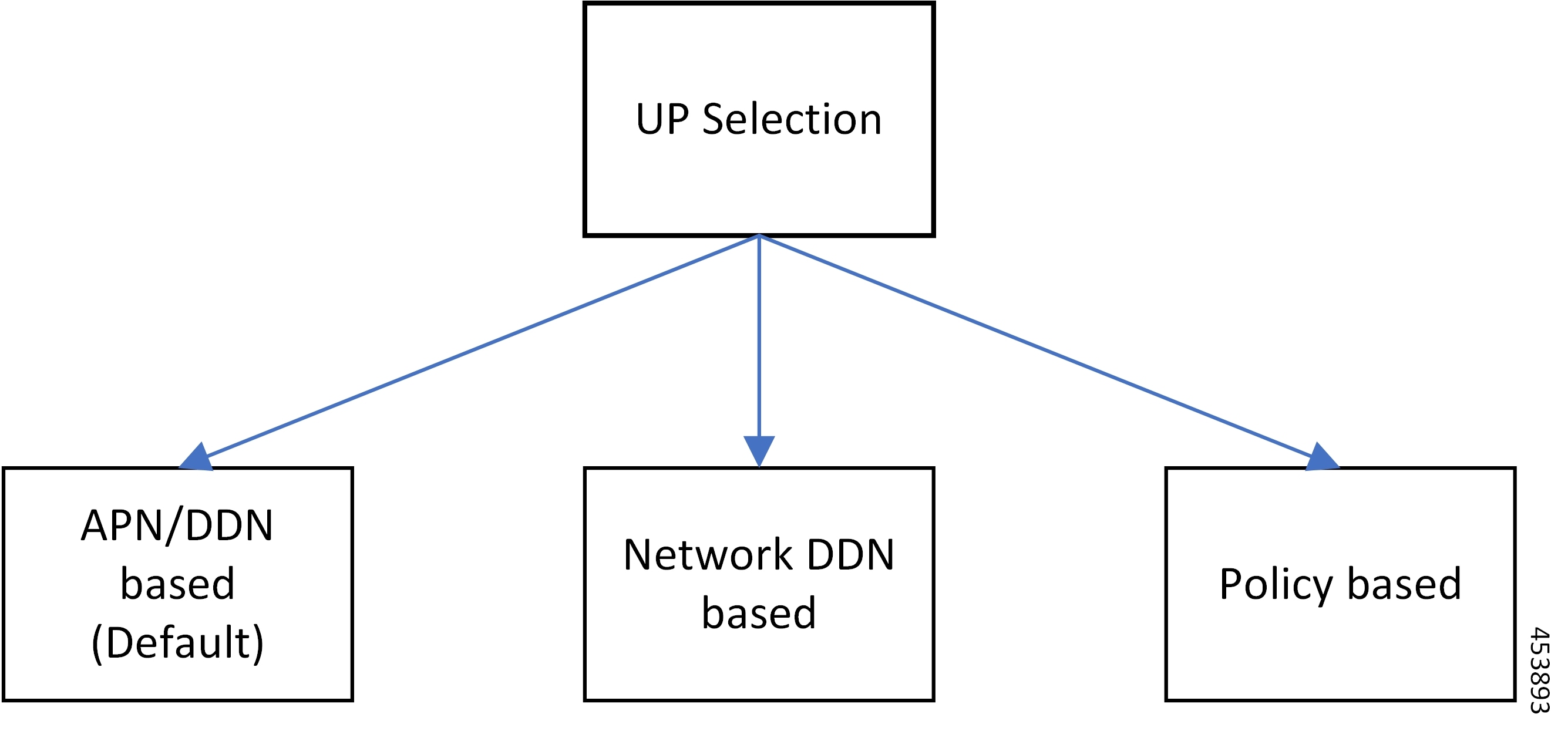
The following are the three UPF selection methods:

  • DNN or APN based

  • Network based

  • Policy based


Note


DNN is enabled when UPF selection policy isn’t associated.


How it Works

This section describes how the feature works.

UPF Selection Methods

DNN or APN Based
  • Create Session request message has APN information. This APN gets configured as part of DNN-list in the Network element profile for each user-plane.

  • The PDN establishment considers these user-planes.

  • UPF selection uses Capacity and Priority if many user-planes are available.

Network Based
  • UPF selection considers DNN which got configured as part of the APN or DNN profile.

  • This DNN is local SGW network specific DNN name.

  • The same network DNN or APN name gets configured as part of DNN-list in the network element profile for each user-plane.

  • Instead of using APN that comes in CSReq, local DNN is used for the UPF selection based on the DNN list.

    For example, in case of roaming scenario where APN is not known, this configuration helps in UPF selection.

  • PDN establishment considers these user-planes.

  • UPF selection uses Capacity and Priority if many user-planes are available.

UPF Selection Policy Based
  • UPF selection profile configuration with parameters determines UPF for each precedence. The supported max number of precedencies are four.

  • Each precedence parameter is a Logical AND condition. If DNN and DCNR are configured as precedence 1, then it searches for the DNN supported user-plane and enables DCNR based support. If this search criteria fails, it moves to the next (mostly 2) precedence and tries to evaluate that condition.

  • UPF selection policy is associated with a DNN profile.

  • UPF group provides characteristics to the network element profile which belongs to the same UPF group profile.

  • UPF selection uses Capacity and Priority if many user-planes available.


Note


  • cnSGW-C rejects the call with Create Session Response specifying cause as NO_RESOURCE_AVAILABLE when no UPF matches the precedence criteria.


Configuring UPF Selection Methods

This section describes how to configure the UPF selection methods.

Configuring UPF Group Profile-based UPF Selection

This section describes how to configure UPF group profile-based UPF selection.

Use the following commands to configure the UPF group profile-based UPF selection.

config 
  profile upf-group upf_group_name 
    dcnr [true | false] 
    end 

NOTES:

  • profile upf-group upf_group_name —Specify the UPF group name. Must be a string.

  • dcnr [true | false] —Specify to enable or disable support for dual connectivity with new radio. Default value is false.

Sample Configuration

Following is a sample configuration.

config
profile upf-group G1
 dcnr true
 end

Configuring Network-based UPF Selection

This section describes how to configure network-based UPF selection.

Use the following commands to configure the network-based UPF Selection.

config 
   profile network-element upfupf_name 
      node-id  node_id_value 
      n4-peer-address ipv4  ipv4_address 
      n4-peer-address ipv6  ipv6_address 
      n4-peer-port  port_number 
      dual-stack-transport { true | false }  
      upf-group-profile upf_group_profile_name 
      dnn-list dnn_list 
      priority priority_value 
      capacity capacity_value 
      end 

NOTES:

  • network-element upf upf_name —Specify the UPF profile name.

  • node-id node_id_value —Specify the Node ID of the UPF node.

  • n4-peer-address ipv4 ipv4_address —Specify the IPv4 address.

  • n4-peer-address ipv6 ipv6_address —Specify the IPv6 address.

  • dual-stack-transport { true | false } —Enable the dual stack feature that allows you to specify IPv6 or IPv4 address. Specify true to enable this feature.

  • upf-group-profile upf_group_profile_name —Specify the UPF group profile name.

  • dnn-list dnn_list —Specify the DNN list supported by UPF node.

  • priority priority_value —Specify the static priority relative to other UPFs. This is used for load balancing. Must be an integer in the range of 0–65535. Default value is 1.

  • capacity capacity_value — Specify the capacity relative to other UPFs. This is used for load balancing. Must be an integer in the range of 0–65535. Default value is 10.

Sample Configuration

Following is a sample configuration.

config
profile network-element upf UP1
 node-id      upf1@sgw.com
 upf-group-profile G1
 dnn-list [dnn1 dnn2]
 priority 20
 capacity 65535
 end

Configuring Policy based UPF Selection

This section describes how to configure Policy based UPF selection.

Use the following commands to configure the Policy based UPF Selection.

config 
 policy upf-selection upf_selection_policyname 
   precedence precedence_value location 
   exit 
   precedence precedence_value dnn 
   exit 
 exit 

NOTES:

  • upf-selection upf_selection_policyname - Specify the UPF selection policy name.

  • precedence precedence_value - Specify the precedence for entry. Must be an integer in the range of 1-4.

Sample Configuration

Following is a sample configuration.

config
policy upf-selection upf_pol1
  precedence 1
    [ location ]
  exit
  precedence 2
    [ dnn ]
  exit
exit

Troubleshooting Information

This section describes the troubleshooting information that enables you to view the UPF selection using DNN and DCNR configuration issues.

Configuration Errors

show config-error | tab
ERROR COMPONENT   ERROR DESCRIPTION
-------------------------------------------------------------------------------------------------------------
SGWProfile        Subscriber policy name : sub_policy in profile sgw1 is not configured
SubscriberPolicy  Operator policy : op_policy1 under subscriber policy sub_policy2 is not configured
OperatorPolicy    Dnn policy name : dnn_policy1 in operator policy op_policy2 is not configured
DnnPolicy         Dnn profile name : dnn_profile1 in dnn policy dnn_policy2 is not configured
DnnProfile        UPF selection policy name : upf_sel_policy1 in dnn profile dnn_profile2 is not configured

UPF Selection using Location Support

Feature Description

This feature supports Location-based UPF selection in Create Session Request message. It performs this selection as per the received TAI or ECGI or both TAI and ECGI values together.

Configuring the UPF Selection Feature

This section describes how to configure the UPF selection using location.

Configuring ECGI for EPS

This section describes how to configure ECGI for EPS.

New configuration and profile ecgi-group added to configure the list of individual ECGI values or the range of ECGI.

You can configure both ECGI list and ECGI range. ECGI range configuration is optional.

Use the following commands to configure the ECGI Configuration for EPS.

config 
   profile ecgi-group ecgi_group_name 
      mcc mcc_value 
      mnc mnc_value 
         ecgi list ecgi_list_name 
         ecgi range start start_value end end_value 
   exit 

NOTES:

  • ecgi-group ecgi_group_name - Specify the ECGI group name.

  • mcc mcc_value - Specify the MCC value. Must be a three digit number. For example, 123

  • mnc mnc_value - Specify the MNC value. Must be a two or three digit number. For example, 23 or 456

  • ecgi list ecgi_list - Specify the list of ECGI values - 7 digit hex string Eutra Cell ID. For example, A12345f. Must be a string.

  • ecgi range start start_value end end_value - Specify the ECGI range start and end values. Must be a string.


Note


  • You can configure multiple ECGI range values.

  • You can configure multiple [PLMN and ECGI values] under ecgi-group configuration.

  • You can configure maximum of 16 PLMNs under ecgi-group configuration.

  • You can configure maximum of 64 ECGI values in the ECGI list under a PLMN.

  • Maximum defined number of ECGI ranges under a PLMN is 64.


Sample Configuration

Following is the sample configuration.

config
profile ecgi-group e1 mcc 123 mnc 45
ecgi list [ 1234567 abcdef0 ]
ecgi range start 1111111 end fffffff
exit
Verifying ECGI for EPS Configuration

This section describes how to verify the ECGI Configuration for EPS.

Use the following show command to view the ECGI configuration for EPS.

show running-config profile ecgi-group
profile ecgi-group e1
mcc 123 mnc 45
ecgi list [ 1234567 abcdef0 ]
ecgi range start 1111111 end fffffff
exit
exit
exit

Configuring TAI-Group

This section describes how to configure TAI-Group.

You can enhance the following TAI-Group configuration to support multiple TAI-Group configurations with different names.

Use the following commands to configure the TAI-Group.

config 
   profile tai-group tai_group_name 
      mcc mcc_value 
      mnc mcc_value 
         tac list tac_list 
         tac range start start_value end end_value 
   exit 

NOTES:

  • tai-group tai_group_name - Specify the TAI group name.

  • mcc mcc_value - Specify the MCC value. Must be a three digit number. For example, 123

  • mnc mnc_value - Specify the MNC value. Must be a two or three digit number. For example, 23 or 456

  • tac list tac_list - Specify the list of TAC values - [0-9a-fA-F]{4}|[0-9a-fA-F]{6} - 4 digit or 6 digit hex string - Example A123, 1a2B3F. Must be a string.

  • tac range start start_value end end_value - Specify the TAC range start and end values. Must be a string.


Note


  • You can configure maximum of 16 PLMNs under a TAI-Group.

  • You can configure maximum of 64 TAC values in a TAC list under a PLMN.

  • Maximum defined number of TAC ranges under a PLMN is 64.


Sample Configuration

Following is the sample configuration.

config
profile tai-group TAI-GRP1
  mcc 123 mnc 234
    tac list [ 1a25 A123 ]
    tac range start B234 end b999
    exit
    tac range start C213 end c999
    exit
  exit
  mcc 231 mnc 45
    tac list [ 2a2B B123 ]
    tac range start d111 end d999
    exit
  exit
exit

Configuring Location-area-group

This section describes how to configure Location-area-group.

You can add new configuration and profile location-area-group. Configuration of ecgi-group and tai-group are optional.

Use the following commands to configure the Location-area-group.

config 
   profile location-area-group location_area_group_name 
      tai-group tai_group_name 
      ecgi-group ecgi_group_name 
   exit 

NOTES:

  • location-area-group location_area_group_name - Specify the location area group name.

  • tai-group tai_group_name - Specify the TAI group name.

  • ecgi-group ecgi_group_name - Specify the ECGI group name.

Sample Configuration

Following is the sample configuration.

config
profile location-area-group LOC_AREA_GRP_1 
  tai-group TAI-AUTO-GRP1 
  ecgi-group ECGI-AUTO-GRP1
exit
profile location-area-group LOC_AREA_GRP_2
  tai-group TAI-AUTO-GRP2
exit

Configuring UPF Group and UPF Selection Policy Enhancement

This section describes how to configure UPF Group and UPF Selection Policy Enhancement.

You can add new configuration under upf-group-profile to configure location-area-group-list.

Use the following commands to configure the UPF group anf UPF selection policy enhancement.

config 
   profile upf-group upf_group_name 
      location-area-group-list [area_group_list] 
   exit 
config 
   policy upf-selection selection_policy_name 
    precedence value  [ selection_parameter_list ] 
   exit 

NOTES:

  • upf-group upf_group_name - Specify the UPF group name.

  • location-area-group-list area_group_list - Specify the list of Location Area Group supported by UPF node.

  • upf-selection selection_policy_name - Specify the UPF selection policy name.

  • precedence value [ selection_parameter_list ] - Specify the precedence for entry. Must be an integer in the range of 1-4.


    Note


    If pdn-type-subscription and pdn-type-session both are configured, pdn-type-subscription is considered.


Sample Configuration

Following is the sample configuration.

config
profile upf-group G1
 location-area-group-list [ LOC_AUTO_GRP_1 ]
exit
profile upf-group G2
 location-area-group-list [ LOC_AUTO_GRP_2 ]
exit
profile upf-group G3
 location-area-group-list [LOC_AUTO_GRP_1 LOC_AUTO_GRP_2 ]
exit
config
policy upf-selection upf_pol1
  precedence 1
    [ location ]
  exit
  precedence 2
    [ dnn ]
  exit
exit

Combined UPF Selection for cnSGW-C and SMF

Feature Description

This feature supports cnSGW-C and SMF to select the same UPF instance when the UPF and SMF are deployed on same cluster and UPF instance is available. If the UPF instance is not available, the UPF selection is based on the existing configurations.

Standards Compliance

The Combined UPF Selection for cnSGW-C and SMF feature complies with the following standards:

  • 3GPP TS 23.401

  • 3GPP TS 23.402

  • 3GPP TS 29.274

  • 3GPP TS 23.214

  • 3GPP TS 29.244

  • 3GPP TS 24.008

How it Works

This section describes how this feature works.

System Architecture

cnSGW-C and SMF/IWF uses the same UPF instance, so that UPF can use those sessions to the collapsed data path.

Control plane (cnSGW-C and SMF) selects the same User-plane in various scenarios (initial attach, handover, and so on).

Following actions takes place during Initial Attach:

  • cnSGW-C passes the SGW-U FQDN information of selected UPF instance to SMF in Initial attach.

  • SMF selects the UPF instance as per the received SGW-U FQDN.

  • Same UPF FQDN is configured at cnSGW-C and at SMF to create a correlation as part of the network element profile.

Call Flows

This section describes the key call flows of Combined UPF Selection for cnSGW-C and SMF feature.

Initial Attach on 4G for 5G Capable Device Call Flow

This section describes the Initial Attach on 4G for 5G Capable Device call flow.

Figure 1. Initial Attach on 4G for 5G Capable Device Call Flow
Table 3. Initial Attach on 4G for 5G Capable Device Call Flow Description

Step

Description

1

Established UPF association with control planes.

cnSGW-C sends Sx Association Req/Rep to UPF.

2

SMF sends Sx Association Req/Rep to UPF.

3

MME sends Create Session Request to cnSGW-C after selecting co-located cnSGW-C and SMF.

4

cnSGW-C sends Sx Establishment Req (SXA) to UPF after selecting UPF using DNN profile, Cell ID, and local factors.

5

cnSGW-C receives Sx Establishment Res from UPF.

6

cnSGW-C sends Create Session Request to SMF including SGW-U FQDN.

7

SMF must find cnSGW-C selected UPF as per received SGW-U FQDN and select the same UPF to achieve data throughput.

SMF tries to select same UPF when IP pools are available. Same UPF supports the PDN type.

SMF may not select same UPF in few in-compatible scenarios.

SMF send Sx Establishment Req N4 to UPF.

8

SMF receives Sx Establishment Res-N4 from UP.

9

cnSGW-C receives Create Session Response from SMF.

10

MME sends Modify Bearer Request to cnSGW-C.

11

cnSGW-C sends Sx Modify Req (SXA) to SMF.

12

cnSGW-C receives Sx Modify Res (SXA) to SMF.

13

cnSGW-C sends Modify Bearer Response to MME.

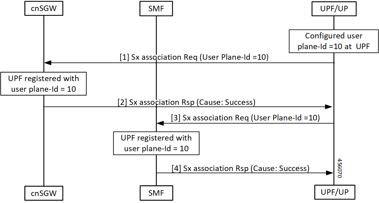
UPF Registration with User Plane ID Call Flow

This section describes the UPF Registration with User Plane ID call flow.

Figure 2. UPF Registration with User Plane ID Call Flow
Table 4. UPF Registration with User Plane ID Call Flow Description

Step

Description

1

Configured User-plane ID at UPF

cnSGW-C receives Sx association Request from UPF with configured User-plane ID.

2

UPF receives Sx association Response with Cause = SUCCESS from cnSGW-C.

3

SMF receives Sx association Request from UPF with configured User-plane ID.

4

UPF receives Sx association Response with Cause = SUCCESS from SMF.

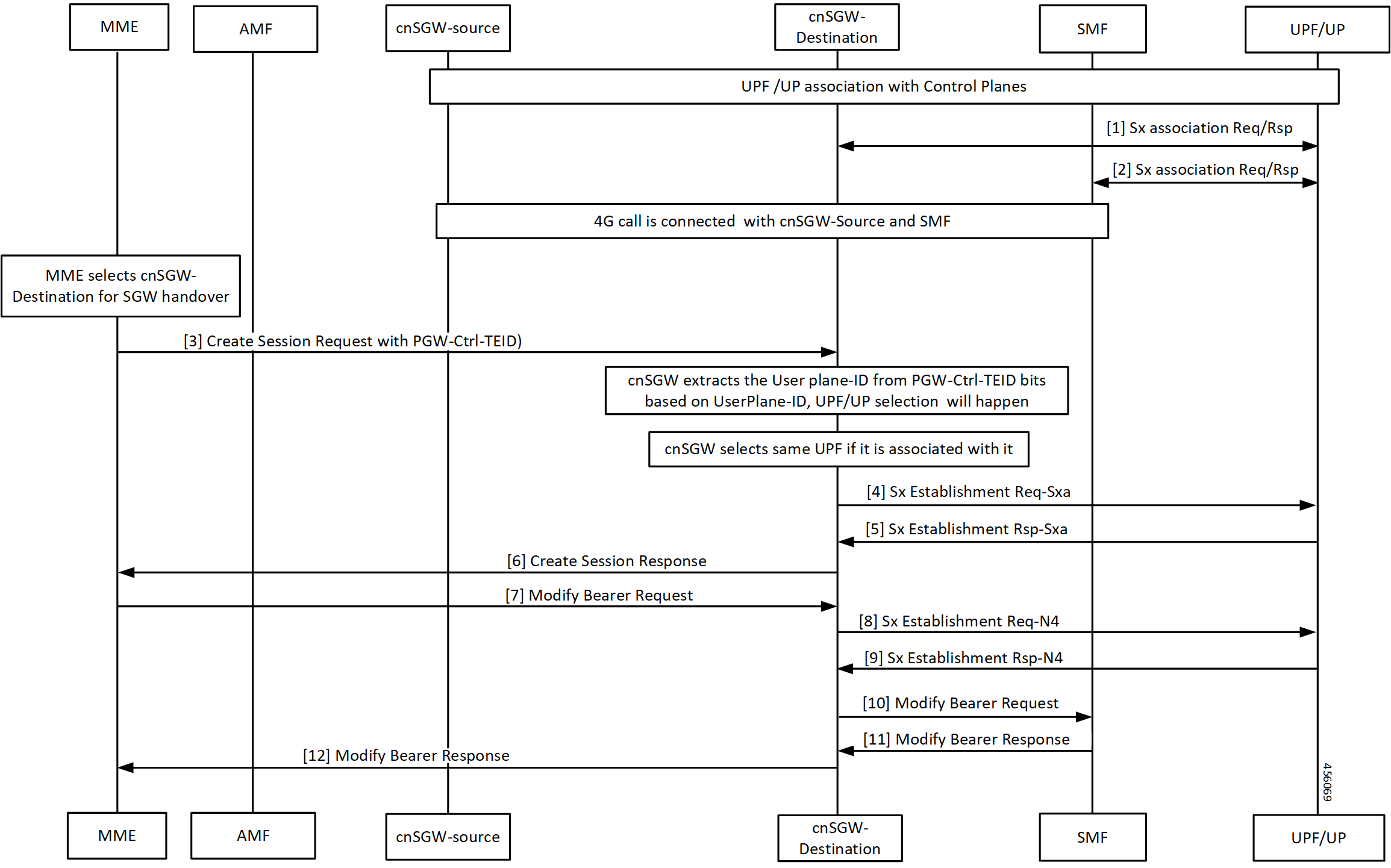
Inter-SGW Handover on 4G RAT for 5G Capable Devices Call Flow

This section describes the Inter-SGW Handover on 4G RAT for 5G Capable Devices call flow.

Figure 3. Inter-SGW Handover on 4G RAT for 5G Capable Devices Call Flow
Table 5. Inter-SGW Handover on 4G RAT for 5G Capable Devices Call Flow Description

Step

Description

1

Established UPF association with control planes.

UPF sends Sx Association Req/Rep to destination cnSGW-C.

2

UPF sends Sx Association Req/Rep to SMF.

3

4G call connected between cnSGW-C-source and SMF.

MME selects cnSGW-C-Destination for the SGW handover.

MME sends Create Session Req with PGW-Ctrl-TEID to cnSGW-C-Destination.

4

cnSGW-C extracts same associated UPF ID from PGW-Ctrl-TEID.

cnSGW-C-Destination sends Sx Establishment Req (SXA) to UPF.

5

cnSGW-C-Destination receives Sx Establishment Rsp (SXA) from UPF.

6

cnSGW-C-Destination sends Create Session Response to MME.

7

cnSGW-C-Destination receives Modify Bearer Request from MME.

8

cnSGW-C-Destination sends Sx Establishment Req-N4 to UPF.

9

cnSGW-C-Destination receives Sx Establishment Rsp-N4 from UPF.

10

cnSGW-C-Destination sends Modify Bearer Request to SMF.

11

cnSGW-C-Destination receives Modify Bearer Response from SMF.

12

cnSGW-C-Destination forwards Modify Bearer Request to MME.

5G to EPS Handover Using N26 Interface – cnSGW-C and SMF Separate Node Call Flow

This section describes the 5G to EPS Handover Using N26 Interface – cnSGW-C and SMF Separate Node call flow.

Figure 4. 5G to EPS Handover Using N26 Interface – cnSGW-C and SMF Separate Node Call Flow
Table 6. 5G to EPS Handover Using N26 Interface – cnSGW-C and SMF Separate Node Call Flow Description

Step

Description

1

cnSGW-C selects associated same UPF.

cnSGW-C receives Sx Establishment Request with User-plane ID from UPF/UP.

2

cnSGW-C sends Sx Establishment Response from UPF/UP.

3

UPF/UP sends Sx Association Request with User-plane ID to SMF.

4

SMF sends Sx Association Response to UPF/UP.

5

cnSGW-C sends Relocation Request to MME on interface N26.

6

MME sends Create Session Request to cnSGW-C with SMF and PGW-ctrl-TEID information.

7

cnSGW-C selects associated same UPF.

cnSGW-C sends Sx Establishment Req (SXA) to UPF/UP.

8

cnSGW-C receives Sx Establishment Rsp (SXA) from UPF/UP.

9

cnSGW-C sends Create Session response to MME.

10

MME sends Modify Bearer Request to cnSGW-C.

11

cnSGW-C sends Sx Modify Req (SXA) to UPF/UP.

12

cnSGW-C receives Sx Modify Rsp (SXA) from UPF/UP.

13

cnSGW-C sends Modify Bearer Request to SMF.

14

SMF sends Sx Modify Request – N4 to UPF/UP.

15

SMF receives Sx Modify Response from UPF/UP.

16

cnSGW-C receives Modify Bearer Response to SMF.

17

cnSGW-C forwards Modify Bearer Response to MME.

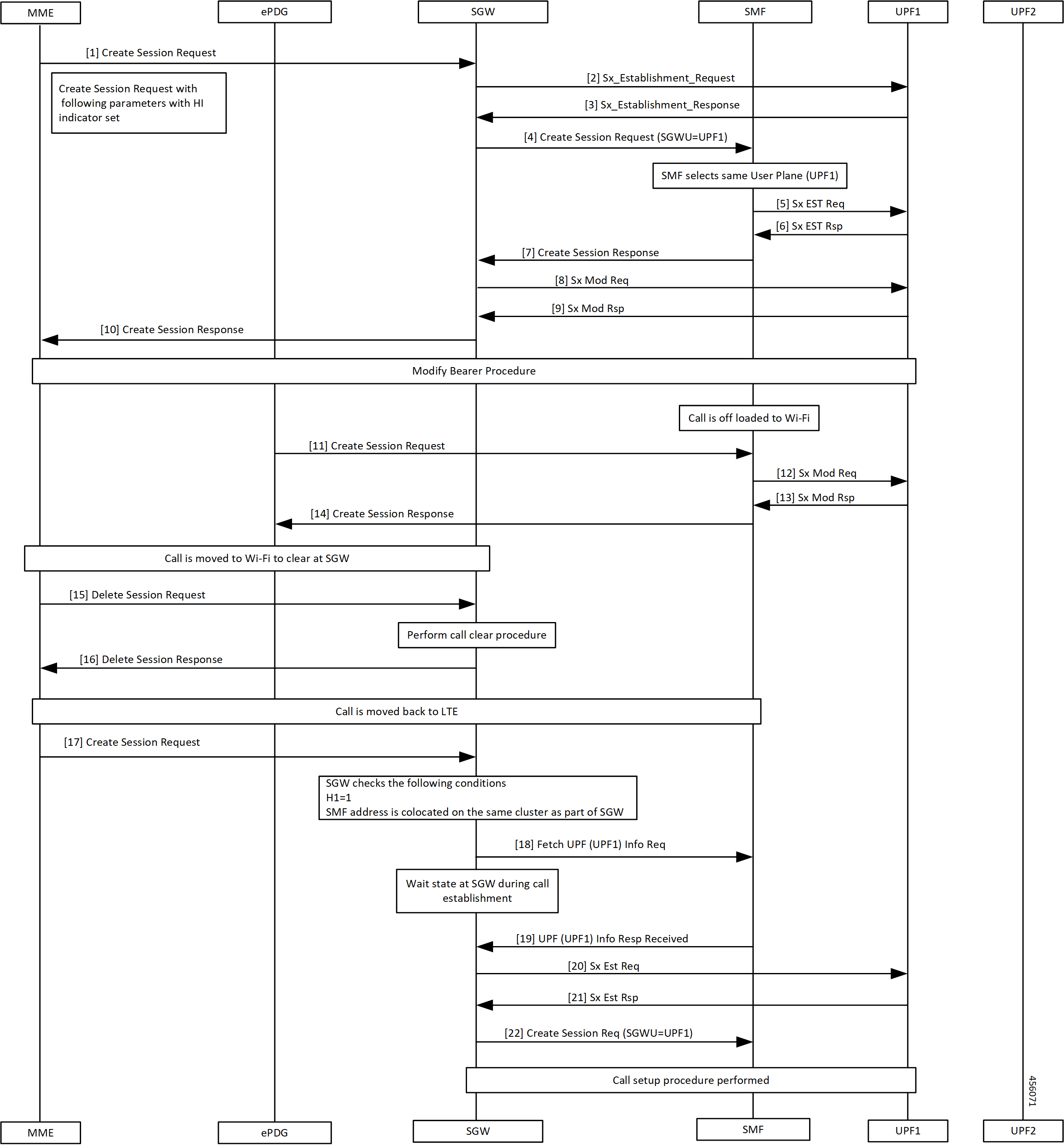
Wi-Fi to LTE Handover Call Flow

This section describes the Wi-Fi to LTE Handover call flow.

Figure 5. Wi-Fi to LTE Handover Call Flow
Table 7. Wi-Fi to LTE Handover Call Flow Description

Step

Description

1

MME sends create Session Request to SGW.

2

SGW sends Sx Establishment Request to UPF1.

3

SGW receives Sx Establishment Response from SMF.

4

SGW sends Create Session Request to SMF. SMF selects same UPF.

5

SMF sends Sx Establishment Request to UPF1.

6

SMF receives Sx Establishment Response from UPF1.

7

SMF sends Create Session Response to SGW.

8

SGW sends Sx Mod Request to UPF1.

9, 10

SGW receives Sx Mod Response from UPF1 and forwards to MME.

11

Modify Bearer procedure takes place and off-loaded call to Wi-Fi.

ePDG sends Create Session Request to SGW.

12

SMF sends Sx Mod Request to UPF1.

13

SMF receives Sx Mod Response from UPF1.

14

ePDG receives Create Session Response from SGW.

15

Call moved to Wi-Fi to clear at SGW.

MME sends Delete Session Request to SGW.

16

MME receives Delete Session Response from SGW after performing call clear procedure.

17

MME sends Create Session Request to SGW.

18

SGW sends fetch UPF (UPF1) info request to SMF after checking SMF as same cluster as cnSGW-C.

19

SGW receives UPF (UPF1) Info Response from SMF.

20

SGW sends Sx Establishment Request to UPF1.

21

SGW receives Sx Establishment Response from UPF1.

22

SGW sends Create Session Request with SGWU=UPF1 to UPF1 and performs call setup procedure.

Configuring the Combined UPF Selection for cnSGW-C and SMF

This section describes how to configure the Combined UPF Selection for cnSGW-C and SMF.

Configuring Converged-Core Profile

This section describes how to configure the Converged-Core Profile.

Use the following commands to configure the profile converged-core with UPF selection enabled.

config 
   profile converged-core core_name 
      max-upf-index value 
      no upf-selection disable 
   exit 

Use the following commands to configure the profile converged-core with UPF selection disabled.

config 
   profile converged-core core_name 
      max-upf-index value 
      upf-selection disable 
   exit 

NOTES:

  • converged-core core_name - Specify the converged core prolile name.

  • max-upf-index value - Specify the UPF index value. Must be an integer in the range of 1-1023.

  • no upf-selection disable - Enable colocated UPF selection.

  • upf-selection disable - Disable colocated UPF slection.

Sample configuration

Following is a sample configuration with UPF selection enabled.

config
profile converged-core cc1
max-upf-index 1023
no upf-selection disable
exit

Following is a sample configuration with UPF selection disabled.

config
profile converged-core cc1
max-upf-index 1023
upf-selection disable
exit
Verifying the Profile Converged-core Configuration

This section describes how to verify the Profile Converged-core configuration.

Use the following show command to view the Profile Converged-Core configuration with UPF selection enabled.

show running-config profile converged-core cc1
profile converged-core cc1
max-upf-index 1023
no upf-selection disable
exit

Use the following show command to view the Profile Converged-Core configuration with UPF selection disabled.

show running-config profile converged-core cc1
profile converged-core cc1
max-upf-index 1023
upf-selection disable
exit

Configuring Node-ID

This section describes how to configure the Node-ID.

Use the following commands to configure the Node-ID.

config 
   profile network-element upf upf_name 
      node-id node_id_value 
   exit 

NOTES:

  • network-element upf upf_name - Specify the UPF peer network element name.

  • node-id node_id_value - Specify the Node ID of the UPF node. Must be a string

Sample Configuration

Following is a sample configuration.

config
profile network-element upf upf1
node-id upf1@cn.com
exit

UPF Selection OAM Support

This section describes operations, administration, and maintenance information for this feature.

Bulk Statistics

UE Disconnect Statistics

sgw_ue_disconnect_stats{app_name="smf",cluster="cn",data_center="cn",instance_id="0",
reason="userplane_info_not_available",service_name="sgw-service"} 24

PDN Disconnect Statistics

sgw_pdn_disconnect_stats{app_name="smf",cluster="cn",data_center="cn",instance_id="0",
pdn_type="ipv4",rat_type="EUTRAN",reason="userplane_info_not_available",service_name="sgw-service"} 8
sgw_pdn_disconnect_stats{app_name="smf",cluster="cn",data_center="cn",instance_id="0",
pdn_type="ipv4v6",rat_type="EUTRAN",reason="userplane_info_not_available",service_name="sgw-service"} 15
sgw_pdn_disconnect_stats{app_name="smf",cluster="cn",data_center="cn",instance_id="0",
pdn_type="ipv6",rat_type="EUTRAN",reason="userplane_info_not_available",service_name="sgw-service"} 1

SGW Service Statistics

sgw_service_stats{app_name="smf",cluster="cn",data_center="cn",fail_reason="userplane_selection_fail",
instance_id="0",interface="interface_sgw_ingress",reject_cause="no_resources_available",service_name=
"sgw-service",sgw_procedure_type="initial_attach",status="failure",sub_fail_reason=""} 22
sgw_service_stats{app_name="smf",cluster="cn",data_center="cn",fail_reason="userplane_selection_fail",
instance_id="0",interface="interface_sgw_ingress",reject_cause="no_resources_available",service_name="sgw-service",
sgw_procedure_type="secondary_pdn_creation",status="failure",sub_fail_reason=""} 2