NAT Configuration

Overview of NAT Configuration

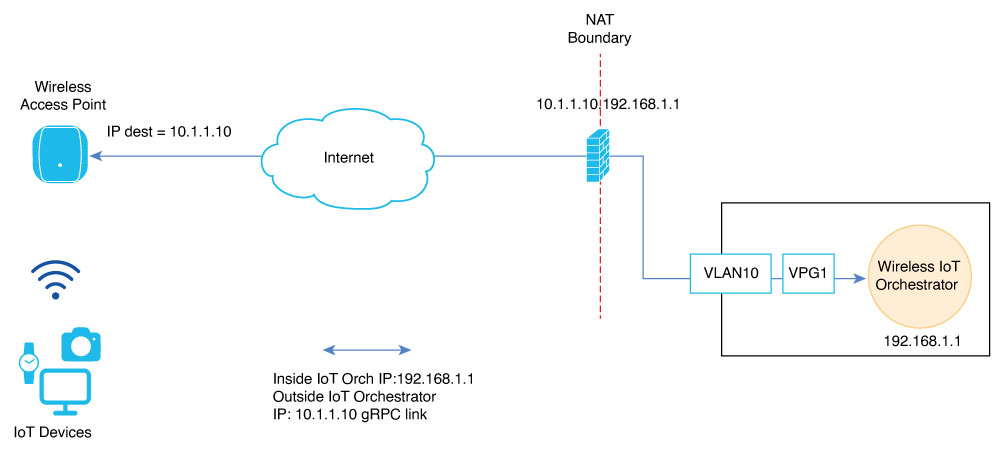
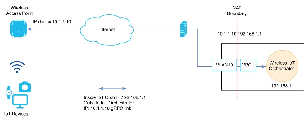
The Cisco Sensor Connect for IoT Services (Wireless IoT Orchestrator) requires Cisco Access Points to establish a TLS connection using GRPC. The default destination target IP address is the Wireless IoT Orchestrator IP address. This IP address is embedded in a JWT token that is passed to APs using AP profile configuration.

In cloud deployments, the IP address configured on Cisco Access Points differs from the IP address configured in the Wireless IoT Orchestrator. This deployment involves NAT to provide reachability over the internet. The NAT IP address field indicates to the Wireless IoT Orchestrator container which destination IP address the Cisco APs can use for GRPC connection.

The NAT IP address field is necessary when the Cisco Catalyst 9800 Wireless Controller is configured to use CAPWAP discovery with a public IP. For more information on CAPWAP discovery with a public IP, see the Wireless Management Interface documentation.

This chapter describes how to use the NAT IP address field in the Cisco Catalyst 9800 Wireless Controller Web UI (Configuration > Services > IoT Services) and configure NAT on the Cisco Catalyst 9800 Wireless Controller for IoT Orchestrator use cases.

Supported Scenarios

The following scenarios are supported for the NAT IP address field in the Wireless IoT Orchestrator:

Figure 1. Schema for NAT Configured External to the Cisco Catalyst 9800 Wireless Controller (Example: In a Perimetral Firewall)

In Figure 1, the external network device (for instance, a perimetral firewall or router) performs NAT or PAT for the Wireless IoT Orchestrator.

Therefore, add the corresponding NAT IP address of the Wireless IoT Orchestrator to the NAT IP Address field.

To add the corresponding NAT IP address for the Wireless IoT Orchestrator, perform the following steps:

  1. Log in to the Cisco Catalyst 9800 Wireless Controller Web UI.

  2. Navigate to Configuration > Services > IoT Services.

  3. Enter the NAT IP address.


    Note


    The NAT IP address determines the destination IP address used by Cisco APs for the GRPC connection.


  4. Click Enable IoT Services.

Figure 2. Schema for NAT Configured on Cisco Catalyst 9800 Wireless Controller

Restrictions

  • Out-of-band management interfaces of the Cisco Catalyst 9800 Wireless Controller hardware appliances (interface configured under vrf Mgmt-intf) cannot be used as an outside interface for NAT.

  • The use of VRFs with NAT configuration for IoT Orchestrator is not supported.

  • Static and dynamic NAT or PAT are supported on all Layer 3 interfaces, including SVIs and physical interfaces configured with the no switchport command.

  • The IP address used as the global address must be an IP address of an interface on the Wireless IoT Orchestrator. For more information, see CSCwn12646.

  • As a best practice, NAT should not be used on the same physical port as the Wireless Management Interface (WMI) when APs are deployed in large-scale local mode, or when the uplink port of the Cisco Catalyst 9800 Wireless Controller has limited bandwidth.

  • When APs are deployed in FlexConnect mode, there is no restriction on the NAT interface being the same as the WMI. For more information on the AP mode deployments, see the Catalyst 9800 Wireless Controller Configuration Model.

    Once the NAT is configured on the Cisco Catalyst 9800 Wireless Controller, the IP address selected as the NAT outside IP address of the Wireless IoT Orchestrator must be configured in the NAT IP Address field as shown in Figure 2.

Examples of NAT Configuration on Cisco Catalyst 9800 Wireless Controller

Prerequisites

  • Before mapping any TCP port, ensure that it is not already in use by the Cisco Catalyst 9800 Wireless Controller. To verify, execute the following commands to ensure that each port is available before you attempt to map it:

    
    Device# show tcp brief | include <tcp port>
    Device# show platform software tcpudpport | include <tcp port>
    

Configuration

The following are the types of configurations:

  • Static NAT – Used for AP GRPC connections to the Wireless IoT Orchestrator or for accessing the Wireless IoT Orchestrator GUI.

  • Dynamic NAT – Used when the Wireless IoT Orchestrator requires an internet connection, leveraging one of the Cisco Catalyst 9800 Wireless Controller interfaces.

Example: Static NAT Configuration

This example demonstrates how to expose ports 50221 and 43626 on a Cisco Catalyst 9800 Wireless Controller. The configuration was performed on a C9800-CL wireless controller running the 17.15.3 image. GigabitEthernet1 is configured as the Wireless Management Interface, and APs are deployed in FlexConnect mode.

Configuration Details:
  • Wireless IoT Orchestrator IP address: 192.168.1.1/30

  • Default Gateway for IoT Orchestrator: 192.168.1.2

  • GigabitEthernet1 IP address: 10.1.1.10/24

To configure static NAT, issue the following commands on the controller:


Device (config)# interface GigabitEthernet1
Device (config-if)# no switchport
Device (config-if)# ip address 10.1.1.10 255.255.255.0
Device (config-if)# ip nat outside
Device (config-if)# exit
Device (config-if)#interface VirtualPortGroup1
Device (config-if)# ip address 192.168.1.2 255.255.255.252
Device (config-if)# ip nat inside
Device (config-if)# exit
Device (config)# ip nat inside source static tcp 192.168.1.1 43626 interface GigabitEthernet1 43626
Device (config)# ip nat inside source static tcp 192.168.1.1 50221 interface GigabitEthernet1 50221
Device (config)# exit

To verify the static NAT configuration details, use the following command:


Device# show platform software nat chassis active F0 translation
Pro  Inside global         Inside local          Outside local         Outside global
tcp  10.1.1.10:43626       192.168.1.1:43626     ---                   ---
tcp  10.1.1.10:50221       192.168.1.1:50221      ---                   ---
Total number of translations: 2

Example: Dynamic NAT Configuration

This example demonstrates how to overload all traffic from the Wireless IoT Orchestrator towards the internet through interface Vlan 180, except for traffic destined for access points. Assume an AP deployment in local mode, adhering to all NAT restrictions and recommendations in this document.

Configuration Details:
  • Wireless IoT Orchestrator IP address: 192.168.1.1/30

  • Default Gateway for IoT Orchestrator: 192.168.1.2

  • Vlan 180 IP address: 172.16.200.100/24

  • IP subnets for access points: 192.168.15.0/24 and 10.10.10.0/24

To configure dynamic NAT, issue the following commands on the controller:


Device(config)# interface Vlan 180
Device (config-if)# ip address 172.16.200.100 255.255.255.0
Device (config-if)# ip nat outside
Device (config-if)# exit
Device (config-if)#interface VirtualPortGroup1
Device (config-if)# ip address 192.168.1.2 255.255.255.252
	WLC(config-if)# ip nat inside
Device (config-if)# exit
Device (config)# ip access-list extended NAT_IOT_ACL
Device (config-ext-nacl)# 10 deny ip host 192.168.1.1 192.168.15.0 0.0.0.255
Device (config-ext-nacl)# 20 deny ip host 192.168.1.1 10.10.10.0 0.0.0.255
Device (config-ext-nacl)# 30 permit ip host 192.168.1.1 any
Device (config)# exit
Device (config)# ip nat inside source list NAT_IOT_ACL interface Vlan 180 overload
Device (config)# exit

To verify the dynamic NAT configuration details, use the following command:


Device# show platform software nat chassis active F0 translation
Pro  Inside global         Inside local          Outside local         Outside global
icmp 172.18.29.7:8743      192.168.1.1:8743      8.8.8.8:8743          8.8.8.8:8743
tcp  172.18.29.7:5062      192.168.1.1:45156     173.37.145.84:443     173.37.145.84:443
Total number of translations: 2