- Gx Services
- Table (CRD) Driven Rule Refresh on Rule Failure
Gx/Sd
Services
Gx Services
This section covers the following topics:
- QoS Profile
- PCC Rules
- Table (CRD) Driven Rules
- Table (CRD) Driven Rule Refresh on Rule Failure
- Custom Features
- Emergency Data Services
- RAN Congestion
- Usage Monitoring
- Bandwidth Monitoring
- Override Control AVP
- Gx RAR Traffic
- Configuring Policies Based on Gx Events
- Common Parameters Used
QoS Profile
Overview
When UE attaches to the network for the first time, it will be assigned default bearer which remains as long as UE is attached. Default bearer is best effort service. Each default bearer comes with an IP address.
This section provides details of Gx default bearer QoS parameters and also explains how CPS derives QoS in different configurations.
Policy Builder Configuration
Case 1- QoS under Gx Profile
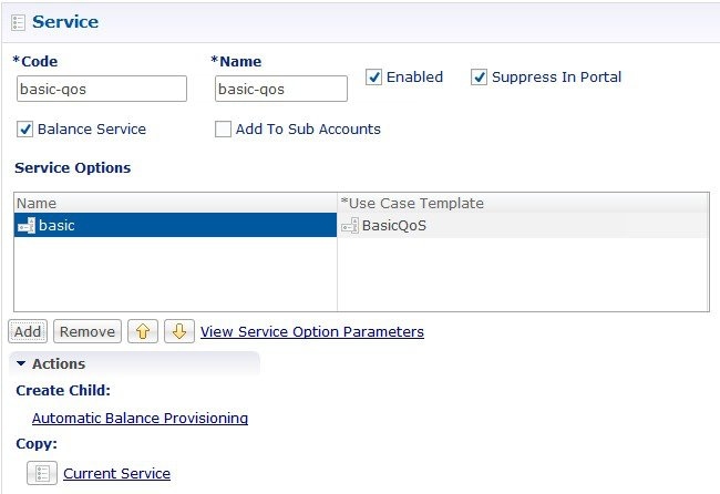
Case 2 - Default Bearer QoS in Service
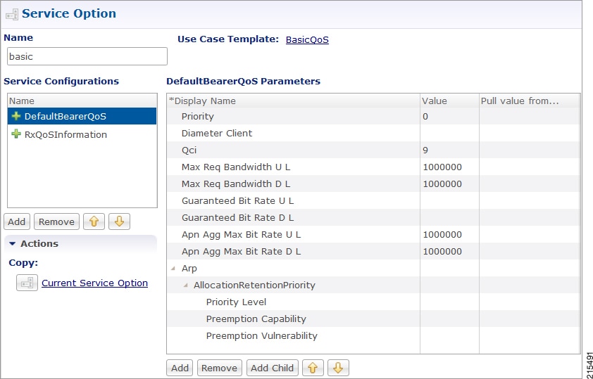
Default Bearer QoS Enhancements - Gx
CPS supports the management of Default Bearer QoS attribute values for IP-CAN sessions by applying QoS-Bounding, QoS-Mirroring and QoS-Enforced on Default Bearer QoS and these actions for individual QoS attributes can be derived based on SPR or Gx session attributes.
-
QoS-Bounding is the ability for the PCRF to calculate the minimum QoS between the Requested QoS (from the P-GW) and the Authorized QoS (based on internal computation of the Logic in the PCRF) and assign that in the response message back to the P-GW.
-
QoS-Mirroring is the ability for the PCRF to mirror the same QoS values back that were being requested by the P-GW in the Request Message.
-
QoS-Enforcement is the ability for the PCRF to enforce the Authorized QoS computed based on its internal logic back to the P-GW in the request/response message.
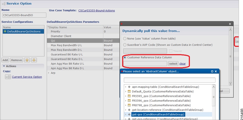
To support QoS Enhancements, the user can configure object DefaultBearerQoSAction with action attribute for each possible QoS attribute and bind to the QoS action columns of the Default Bearer CRD. Also CPS binds the DefaultBearerQoS service configuration object attributes to QoS columns of the Default Bearer CRD.
CPS when sends or receives a Gx request message then it needs to do a lookup from CRD tables for a match of input attributes and perform calculation of DefaultBearer QoS using values from the output attributes and the default configured in service. The QoS Actions are also applicable to PreConfigured Rules defined in CPS service configurations and are used to calculate the QoS-Information grouped AVPs of such charging rules.
CPS after calculation of default bearer QoS applies the QoS actions bounding, mirroring and enforcement to each attribute of current calculated QoS. A new class QoSInformationActions is used to override the QoS calculated from the QoSInformation and assigning the values as defined by CRD table and corresponding action from DefaultBearerQoSAction.
The DefaultBearerQoS calculations explained above are applied if the service configuration contains the service object DefaultBearerQoSAction.
CPS also supports the Gx TGPP session to store the last received QoS parameters from PCEF/PGW which helps in evaluating the QoS during CCR-U or RAR trigger.
CPS also supports QoS calculations for MPS and it takes precedence over QoS Actions while calculating default bearer QoS as shown below:
MIRRORING ACTION
|
CCR (INPUT) |
Calculated QoS Value |
QoS Action |
CCA (OUTPUT) |
|---|---|---|---|
|
MBR |
MBR |
MIRROR |
MBR |
|
GBR |
GBR |
MIRROR |
GBR |
|
QCI |
QCI |
MIRROR |
QCI |
|
ARP |
ARP |
MIRROR |
ARP |
ENFORCING ACTION
|
CCR (INPUT) |
Calculated QoS Value |
QoS Action |
CCA (OUTPUT) |
|---|---|---|---|
|
MBR |
MBR |
ENFORCE |
MBR |
|
GBR |
GBR |
ENFORCE |
GBR |
|
QCI |
QCI |
ENFORCE |
QCI |
|
ARP |
ARP |
ENFORCE |
ARP |
BOUNDING ACTION
|
CCR (INPUT) |
Calculated QoS Value |
QoS Action |
CCA (OUTPUT) |
|---|---|---|---|
|
MBR |
MBR |
BOUND |
min(MBR, MBR) |
|
GBR |
GBR |
BOUND |
min(GBR, GBR) |
|
QCI |
QCI |
BOUND |
max(QCI, QCI) |
|
ARP-PL |
ARP-PL |
BOUND |
max(PL, PL) and PV, PC based on chosen ARP |
|
ARP-PV |
ARP-PV |
BOUND |
Set based on PL. IF PL comes from CCR set CCR Value, or retain Granted QoS Values |
|
ARP-PC |
ARP-PC |
BOUND |
Set based on PL. IF PL comes from CCR set CCR Value, or retain Calculated/Granted Values |
Creating the CRD Table
The user must take special care while defining the CRD table to avoid an unconditional loop in case CRD uses cross referencing data from one table to another table.
Parameter Descriptions
The following table contains a list of common parameters:
|
Parameter |
Description |
|---|---|
|
Grant Requested QoS |
It controls whether the requested QoS should be granted or not as the default bearer QoS. Default value is unchecked. |
|
Gx Client QoS Exclusion List |
Gx client names that are allowed not to have a default bearer QoS installed. |
|
Grant Requested QoS Over Global QoS |
If this flag is checked then requested QoS takes priority over default QoS. Default value is unchecked. |
 Note | For description/usage of other parameters, see Common Steps. |
Default Bearer QoS Algorithm
|
Service Configuration |
Requested QoS |
Granted QoS |
|
|---|---|---|---|
|
Yes |
Yes |
Follow the rules mentioned in QoS Authorization Algorithmfor Granted QoS calculation. |
|
|
Yes |
No |
Granted configured. |
|
|
No |
Yes |
Reference data parameter value is “Yes”. |
Grant requested QoS. CPS can throttle the user based on the use case. |
|
Reference data parameter value is “No”. |
Grant QoS using defaults values. If default values are not available, reject the request. CPS must define Gx QoS defaults like QCI, bit rates. |
||
|
No |
No |
Grant QoS using defaults values. If default values are not available, reject the request. CPS must define Gx QoS defaults like QCI, bit rates. |
|
QoS Authorization Algorithm
CPS uses the following rules to calculate granted QoS. For default bearer, configured QoS refers to Default-Bearer-QoS and for dedicated bearers configured QoS refers to Max-QoS.
|
IP-CAN-Type/RAT-Type |
Evaluation Criteria |
Granted QoS |
||
|---|---|---|---|---|
|
IP-CAN:GPRS RAT Type: Any |
Evaluate QoS-Upgrade, QoS-Negotiation |
QoS-Negotiation |
QoS-Upgrade |
Result |
|
Yes |
Yes |
If Requested QoS > configured QoS: Grant Configured If Requested QoS < configured QoS: Upgrade to configured |
||
|
Yes |
No |
Requested QoS > configured QoS: Grant configured QoS Requested QoS < configured QoS: Grant Requested QoS |
||
|
No |
Yes |
Requested QoS > configured QoS: Reject with BEARER_NOT_AUTHORIZED Requested QoS < configured QoS: Grant Requested QoS |
||
|
No |
No |
Requested QoS > configured QoS: Reject with BEARER_NOT_AUTHORIZED Requested QoS < configured QoS: Grant Requested QoS |
||
|
=3GPP-EPS, RAT-Type = GERAN/UTRAN/EUTRA N |
Evaluated based on IP-CAN-Type |
Provision both QoS-Information and Default-EPS-Bearer-QoS. If Requested QoS > configured QoS: Grant Configured QoS If Requested QoS < configured QoS: Upgrade to configured QoS |
||
|
If RAT-Type is GERAN |
Follow the rules as in IP-CAN-Type GPRS. |
|||
|
IP-CAN-Type=Non-3G PP-EPS |
Evaluate based on IP-CAN-Type |
Provision both QoS-Information and Default-EPS-Bearer-QoS. |
||
|
IP-CAN-Type=DOCSIS (1), xDSL (2), WiMAX (3), 3GPP2 (4) |
Evaluate based on IP-CAN-Type |
Reject CCR request with DIAMETER_ERROR_BEARER_NOT_AUTHORIZED (5143) result code. |
||
PCC Rules
Overview
The purpose of the PCC rule is:
-
To detect a packet belonging to an SDF to map that packet to proper IP-CAN bearer in downlink and uplink direction
-
To identify the service
-
To provide appropriate applicable charging
-
To provide policy control
There are two different types of PCC rules:
-
Dynamic PCC rules: These PCC rules are dynamically provisioned by PCRF to PCEF over Gx interface.
-
Pre-defined PCC rules: These PCC rules are pre-configured in the PCEF. The PCRF can advise the PCEF to activate a set of PCC rules over Gx interface.
CPS can be configured to re-attempt to install PCC rules that fail to install or activate. See Rule Retry Profiles for more information.
Policy Builder Configuration
| Step 1 | Log into Policy Builder. | ||||||||||||||||||||
| Step 2 | Select the Services tab, and then click . | ||||||||||||||||||||
| Step 3 | Click Use Case Template link from the right side under Create Child to create a use case template for PreConfiguredRule. | ||||||||||||||||||||
| Step 4 | Enter the name for use case template. For example, name the new template as PreConfiguredRule. | ||||||||||||||||||||
| Step 5 | Select Actions tab. | ||||||||||||||||||||
| Step 6 | Click Add to open the Select Service Configuration dialog box. | ||||||||||||||||||||
| Step 7 | Select PreConfiguredRule, PreDefinedRule, and PreDefinedRuleBase one after another, and select the required service configuration parameters. | ||||||||||||||||||||
| Step 8 | Click
OK to add the service in the
Service
Configuration pane.
A PCC rules consists of following parameters:
| ||||||||||||||||||||
| Step 9 | On the
Services tab, click
to create a service option and add the
configured use case template.
| ||||||||||||||||||||
| Step 10 | On the Services tab, click to create a service and add the configured use case template. |
Table (CRD) Driven Rules
Overview
ASR5K supports handling of Service Group QoS and defines new Gx AVPs which are exchanged between PCEF and PCRF. Additionally, CPS (PCRF) already supports various use cases related to PCC Rules provisioning and usage monitoring control as defined in 3GPP specification 29.212. Also, the new AVPs related to CISCO Service Group QoS are already supported in CPS.
This feature uses capabilities of Custom Reference Data tables and Search Table Group functionality of CPS.
CPS supports defining a Custom Reference Data table where in all sub-elements of Cisco QoS Group rules are possible to be configured with different values for each element. Also, it is possible to group these rules under a logical group. The application at run time supports queries based on this configured logical group, and Search Table Group, and is able to retrieve all applicable CISCO Service QoS Group rules and its sub-elements.
This feature can be configured by using three service options namely, TableDrivenCiscoQosGroupRule (For Cisco QoS Group rules), TableDrivenChargingRule (For dynamic PCC rules), and TableDrivenPredefinedChargingRule (For predefined PCC charging rules) . Description of their common parameters is listed in the following table.
Note | Currently, Table Driven Rules does not support wildcards. |
|
Parameter |
Description |
|---|---|
|
Search Group |
Search Group is a constant value which CPS uses to search within the Search Table Group indicated by “Search Table” element. |
|
Search Column |
Search Column must be bound to the Key column of the STG (which must be given a data type of Text). |
|
Rule Name Source |
Rule Name Source must be a key column as well. This filed must be bound to the rule name column within the STG which should be Text. |
|
Parameter |
Description |
|---|---|
|
Flow Status Source |
Flow Status Source must be bound to the Flow status column within the STG which should be Text. |
|
Monitoring key Source |
Monitoring key Source must be bound to the Monitoring Key column within the STG which should be Text. |
|
Encoding format Source |
Encoding format Source must be bound to the Encoding format column within the STG which should be either Boolean or Text. If this is defined as Text Data Type then Valid Values must be provided as (True/False). |
|
Redirect Enabled Source |
Redirect Enabled Source must be bound to the Redirect Enabled column within the STG which should be either Boolean or Text. If this is defined as Text Data Type then Valid Values must be provided as (True/False). |
|
Redirect Address Type Source |
Redirect Address Type Source must be bound to the Redirect Address Type column within the STG which should be Text. |
|
Redirect Address Source |
Redirect Address Source must be bound to the Redirect Address column within the STG which should be Text. |
|
Use Override Server Address |
Use Override Server Address must be bound to the Use Override Server Address column within the STG which should be either Boolean or Text. If this is defined as Text Data Type then Valid Values must be provided as (True/False). If this flag is true then it will take the address from the service option and if it is false then it would not override the redirect server address. |
|
Parameter |
Description |
|---|---|
|
Input List (List) |
|
|
Crd Column |
The Crd column is bound to the appropriate key column within the STG for those AVPs which are inputs to this table. |
|
Referenced Output Column |
Reserved for future use. |
|
Column Value |
The value of the AVP that is bound to the Crd Column and has a single value. |
|
Referenced MultiValue AVP Name |
The name of the attribute that is bound to the Crd Column and has multiple values. |
Policy Builder Configuration
Table Driven Cisco QoS Group Rule
| Step 1 | Log into Policy Builder. |
| Step 2 | Select the Services tab, and then click . |
| Step 3 | Click
Use Case
Template link from the right side under
Create
Child to create a use case template for
TableDrivenCiscoQosGroupRule.
|
| Step 4 | Select . |
| Step 5 | Click the
Service
Option link from the right side under
Actions to create a service option using the
TableDrivenCiscoQosGroupRule use case template.
For usage of common parameters, see Common Parameter Descriptions. |
| Step 6 | To bind the
Value, select the name from the
Display
Name column and in
Value column click ....
to open
Please
select a 'CustomerReferenceDataTable' object.
See Common Steps to continue with the configuration. |
Table Driven Charging Rule
| Step 1 | Log into Policy Builder. | ||||||||||||||||||||||||||||||||||||||||||||||||||||||||||||||
| Step 2 | Select the Services tab, and then select . | ||||||||||||||||||||||||||||||||||||||||||||||||||||||||||||||
| Step 3 | Click
Use Case
Template link from the right side under
Create
Child to create a use case template for Table Driven Charging Rule.
| ||||||||||||||||||||||||||||||||||||||||||||||||||||||||||||||
| Step 4 | Select . | ||||||||||||||||||||||||||||||||||||||||||||||||||||||||||||||
| Step 5 | Click the
Service
Option link from the right side under
Actions to create a service option using the
TableDrivenChargingRule use case template.
For usage of common parameters, see Common Parameter Descriptions. Other parameters can be configured as follows:
| ||||||||||||||||||||||||||||||||||||||||||||||||||||||||||||||
| Step 6 | To bind the value, click the Value field, and then click ... to select a value. | ||||||||||||||||||||||||||||||||||||||||||||||||||||||||||||||
| Step 7 | Select the
required object to bind and click
OK.
A sample selection is shown as follows: 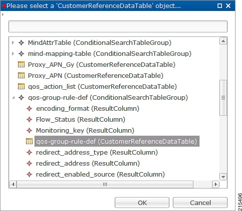 See Common Steps to continue with the configuration. | ||||||||||||||||||||||||||||||||||||||||||||||||||||||||||||||
Table Driven Predefined Charging Rule
| Step 1 | Log into Policy Builder. |
| Step 2 | Select the Services tab, and then select . |
| Step 3 | Click
Use Case
Template link from the right side under
Create
Child to create a use case template for Table Driven Predefined
Charging Rule.
|
| Step 4 | Select . |
| Step 5 | Click the
Service
Option link from the right side under
Actions to create a service option using the
TableDrivenPredefinedChargingRule use case template.
For description/usage of common parameters, see Overview and Common Parameter Descriptions. |
| Step 6 | To bind the value, click the Value field and enter a value or click ... to select a value. |
| Step 7 | Select the
required object to bind and click
OK.
A sample selection is shown as follows: See Common Steps to continue with the configuration. |
Common Steps
| Step 1 | Since this approach leverages Custom Reference and Search Table Group capabilities of CPS, we need to configure a Search Table Group to be able to use the above Service Configuration to configure a Search-Group-Table with the output column specified. | ||
| Step 2 | It is possible
to retrieve the redirect Address related elements of CISCO Service Group QoS
from another table.
|
Control Center Configuration
CRD Supported Features
Table Driven Rule Name Support
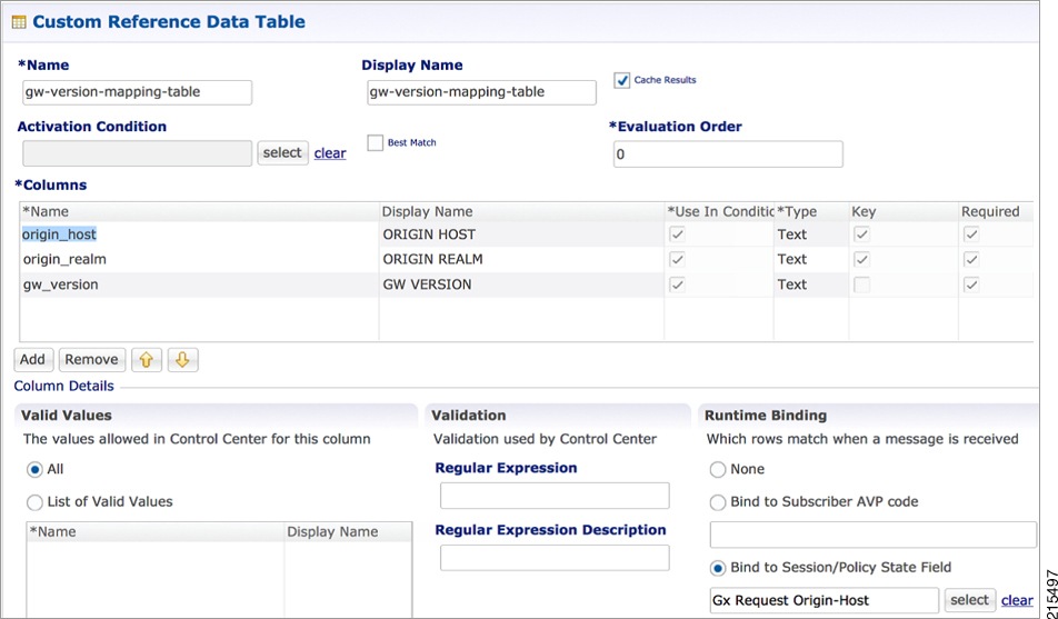
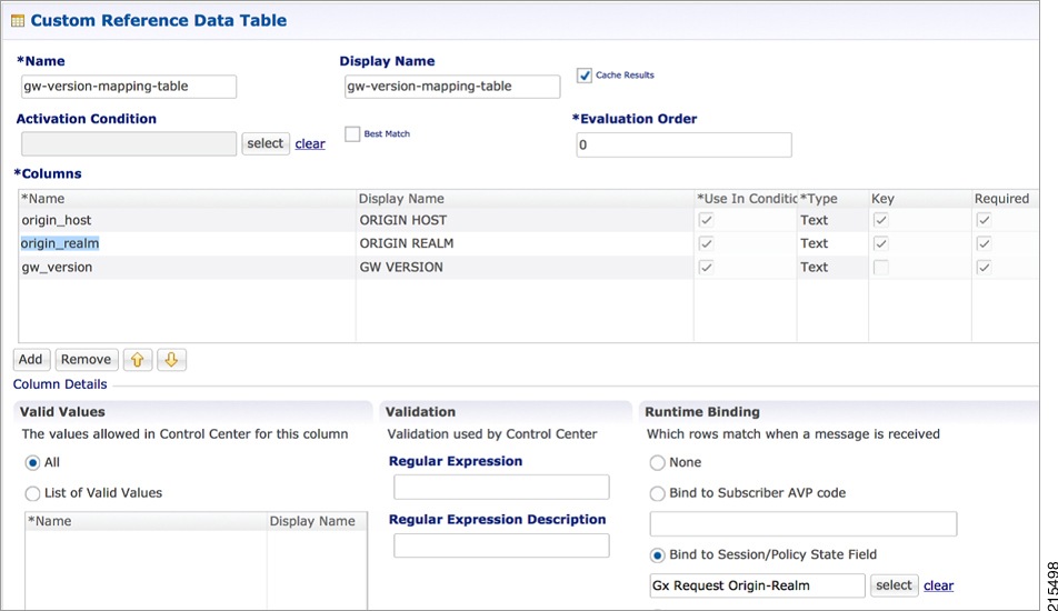
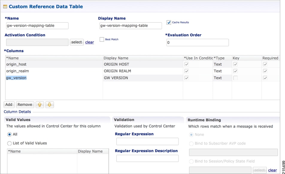
This feature allows CPS to filter the table generated rules (TableDrivenCiscoQosGroupRule, TableDrivenChargingRule, and TableDrivenPredefinedChargingRule) based on what the PCEF supports (via another rule list from CRD). Only rules common to both tables are included in actual policy.
| Step 1 | Create a new
STG/CRD called 'gw-version-mapping-table'.
   | |||||||||
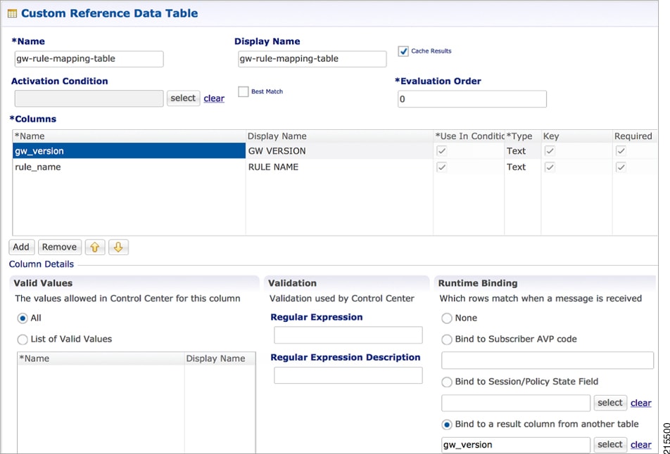
| Step 2 | Create another
STG/CRD called 'gw-rule-mapping-table'.
 | |||||||||
| Step 3 | In the existing 'QoS-Group-Rules' template (where we already have the Table Driven objects) add the new object 'TableDrivenRuleNameSupport'. | |||||||||
| Step 4 | In the same
Service Configuration Object 'QoS-Group-Rules', then click add. The new service
configuration object (added in the template) is available here.
Update the following fields in the new service configuration object:
With this configuration, CPS would do a UNION operation with the QoS groups obtained from the new 'TableDrivenRuleNames' Object (based on the GW version) and the ones retrieved from 'TableDrivenCiscoQoSGroupRules' (based on Rule-Mapping table & Rule-Group-Mapping table). Mapping for Search Table of TableDrivenRuleNameSupport: 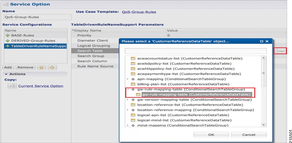 Mapping for Search Group of TableDrivenRuleNameSupport: 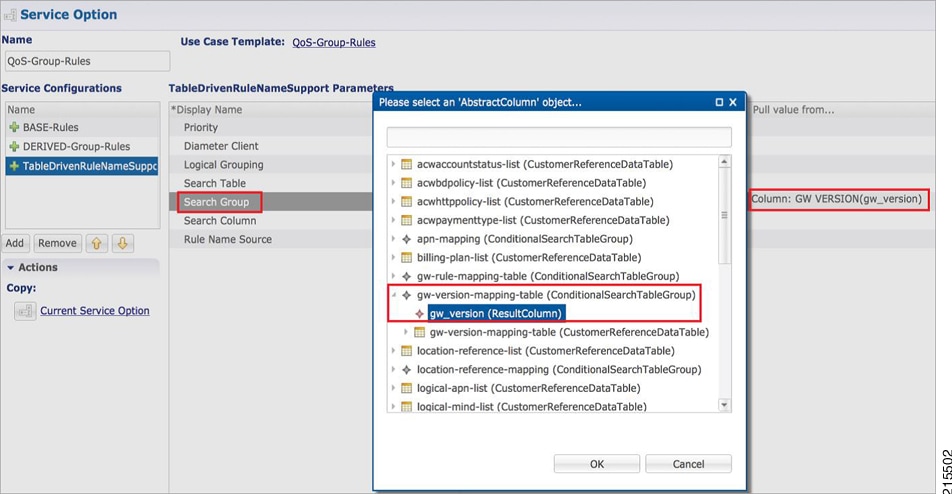 Mapping for Search Column of TableDrivenRuleNameSupport: 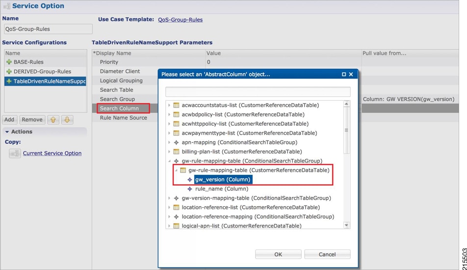 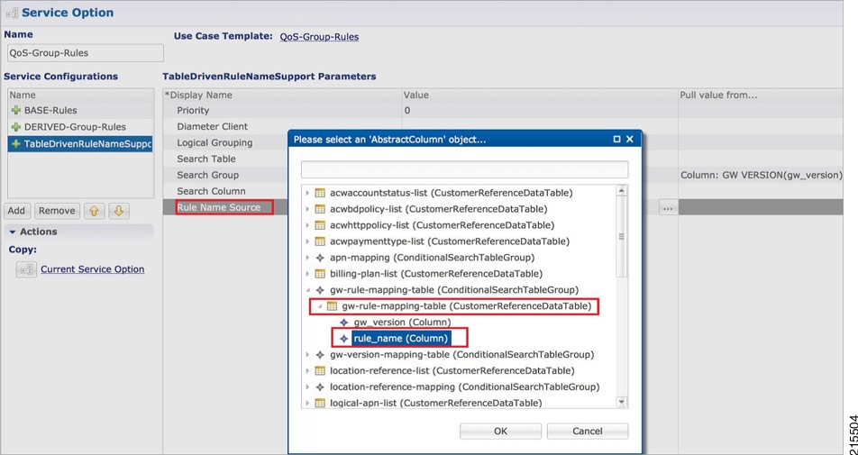 |
Best Match Table Logic
CPS supports each table look-up in CRD, which needs to be one of the match types shown in the following list, along with Best Match table. This approach is fast, efficient, and very easy to troubleshoot, and scales when there are dozens, scores, or hundreds of combinations of values.
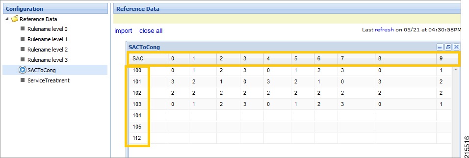
When the Best Match option is selected in the Custom Reference Data Table configuration, look-ups occur within a CRD table in the following order:
-
Exact string match
-
Higher priority regex match (if multiple regex patterns match)
-
Regular expression match (default behavior)
-
Wild card character (*)
The following figures contain examples of a CRD table configuration and its corresponding output table in Control Center.
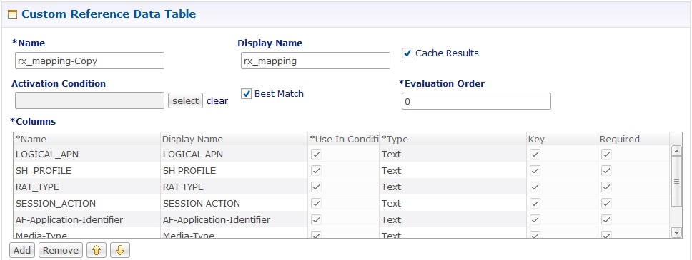
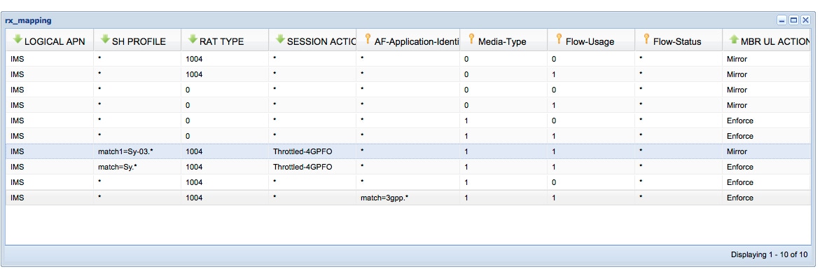
Table (CRD) Driven Rule Refresh on Rule Failure
Overview
CPS now supports the ability to install new charging rules based on the Charging rule name and its status reported in CCR-U from PCEF in Charging Rule Report AVP for a particular rule/rules.
-
The rule name and rule status (ACTIVE(0)/INACTIVE(1)/TEMPORARILY_INACTIVE(2)) are derived from the session and then used as input for the new rules to be installed for the Gx session.
-
If a rule status is received as NOT ACTIVE in CCR-U and if that rule is present as an input in the refresh table on which CPS should install new refresh rules, CPS will remove the rule in CCA-U and install the corresponding newly derived refresh rules from the table in CCA-U.
-
Later if one of the new or derived refresh rules installed above comes with a Charging-Rule-Report as ACTIVE/INACTIVE/TEMP_INACTIVE, CPS will install the default bearer rule back again.
TableDrivenChargingRuleRefresh Service Option
The TableDrivenChargingRuleRefresh service option provides support for this functionality. The specific parameters provided in this service option are described later in Table in section Create a Table Driven Refresh Rule.
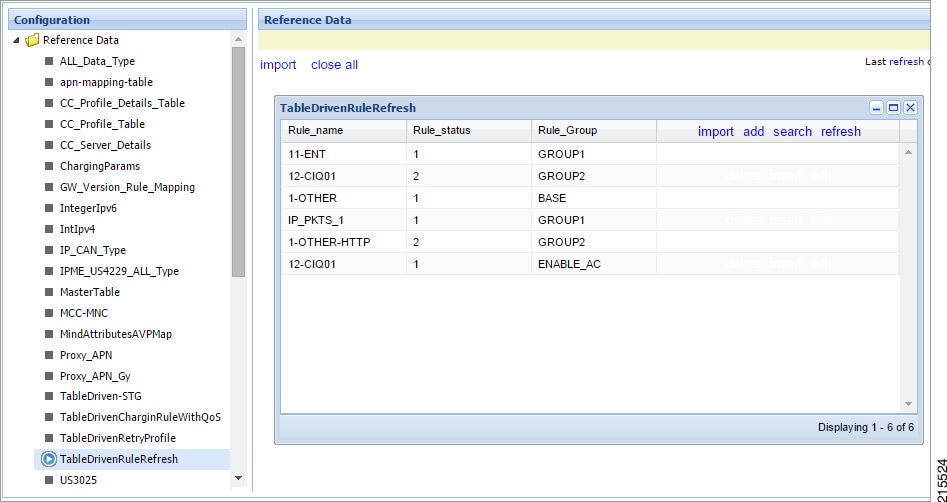
On receiving a Charging-Rule-Report AVP in Gx CCR-U, the TableDrivenRuleRefresh service option is evaluated to find if there are rows configured for the reported rule-name and reported rule-status in the table defined in the Search Table field. If there is an entry in the table, CPS takes the entry from the Output Rule Group Column and uses that value as an input for Search Group in the Table Driven Charging Rule.
If Output Search Table is configured for TableDrivenChargingRuleRefresh, CPS performs a lookup only on those TableDrivenChargingRule objects which has the Search Table matching the Output Search Table in TableDrivenChargingRuleRefresh.
If multiple rules are reported in a Gx-CCR U, then all the corresponding groups in the table are used as an input to TableDrivenChargingRule service option and all the rules from all the groups are evaluated.
The following table shows an example configuration:
|
Rule Name |
Rule Status |
Rule Group |
|---|---|---|
|
Rule-A |
2 |
Group-1 |
|
Rule-B |
2 |
Group-2 |
|
Rule-C |
0 |
Group-3 |
In this example, if CPS receives Rule-A and Rule-B in the ChargingRule Report AVP, then the corresponding groups, Group-1 and Group-2 are evaluated. This is then used to query the TableDrivenChargingRule table with Search Group as Group-1 and Group-2. So all the rules with Group as Group-1 and Group-2 would be installed in CCA-U.
Note |
|
Policy Builder Configuration
Create a Table Driven Rule Refresh CRD Table
| Step 1 | In Policy
Builder, create and configure a Search Table Group (STG) as shown below:
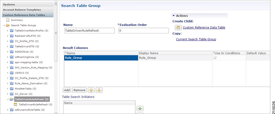 |
| Step 2 | Create and
configure a
Custom Reference Data Table under this STG:
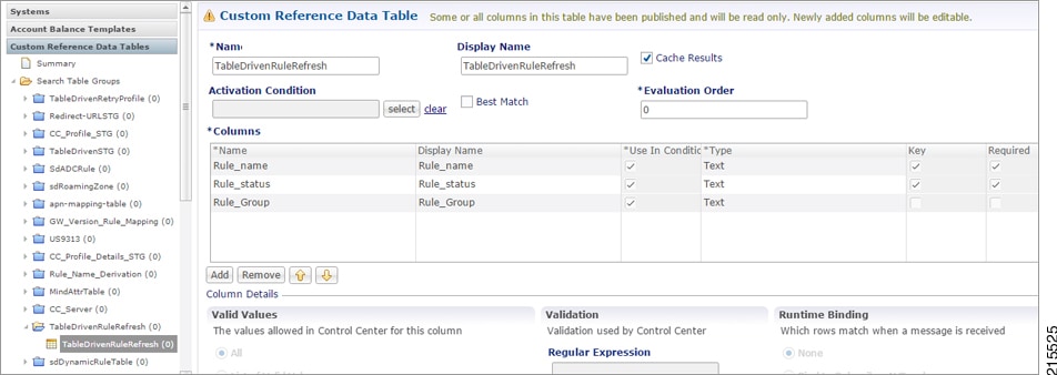 The Rule_Group output column shown above is used as an input to evaluate TableDrivenChargingRule service option. |
Create a Table Driven Refresh Rule
| Step 1 | Log into Policy Builder. | ||||||||||||||
| Step 2 | Select the Services tab, and then click . | ||||||||||||||
| Step 3 | Click Use Case Template link from the right side under Create Child to create a use case template for TableDrivenChargingRuleRefresh. | ||||||||||||||
| Step 4 | Select . Click Service Option link from the right side under Actions to create a service option using Use Case Template created above. | ||||||||||||||
| Step 5 | In the Search
Table row, select the ‘TableDrivenRuleRefresh’ CRD table created in the
previous section to bind it to this service option.
To bind the value, select the name from the Display Name column and in Value column click .... to open Please select a 'CustomerReferenceDataTable' object.
The Output Search Table in TableDrivenChargingRuleRefresh should match with the Search Table in the TableDrivenChargingRule for looking up the output groups in the table for deriving the table driven charging rules. The Search Group in TableDrivenChargingRules is not bound to anything. The output Rule_Group from the Refresh Table is automatically taken as input to the TableDrivenChargingRules service option. |
Control Center Configuration
Prevention of a Refresh Loop
To prevent a scenario where successive INACTIVE statuses would cause CPS to repeatedly attempt to install the same 2 rules, CPS tracks the number of times a refresh rule is installed within a specific time period. If a loop is detected, CPS will skip the rule installation.
The settings which control the loop detection can be customized. Contact your Cisco representative for more information.
Custom Features
Service Group QoS
Overview
The goal of Service Group QoS is to provide support within PCRF in ASR5K to define and enforce Fair-Usage-Policy (FUP) per subscriber. CPS provides support for CISCO Service Group QoS in ASR5K based deployment of PCEF. Service Group QoS is sent over the Gx interface when CPS (PCRF) tries to install or remove rules for a subscription based on various triggers. These attributes are CISCO deployment specific and are enabled only for the “Gx clients” which support Service Group QoS Rules.
Policy Builder Configuration
| Step 1 | Log into Policy Builder. |
| Step 2 | Select the Services tab, and then click . |
| Step 3 | Click
Use Case
Template link from the right side under
Create
Child to create a use case template for
CiscoQoSGroupRule.
|
| Step 4 | Select CiscoQoSGroupRule and click required service configuration parameters that need to be configured. Click OK to add the service in Service Configuration pane. |
| Step 5 | In Services tab, click to create a service option and add the configured Use Case Template in CiscoQoSGroupRule to configure Service Option. |
| Step 6 | In Services tab, click to create a service and add the configured Use Case Template in CiscoQoSGroupRule to configure Service. |
Content Filtering
Overview
The goal of Content Filtering is to provide support for content filtering within the network by use of Policy ID's. Policy identifiers (Policy IDs) are rules that are configured on the ASR 5000 platform and invoked by the CPS. Policy IDs are used to implement the required Content Filtering policies defined for the subscriber. The Policy IDs are selected at the ASR 5000 by provisioning their values through the Gx interface by the PCRF.
When a user initiates a session, the ASR5K communicates with the CPS to initialize the defined policies. CPS provides the Policy ID to the ASR5K to provide the necessary Content Filtering services for the user.
The main aim of this feature is for CPS to provide Policy ID's configured in the subscriber's service to the PCEF (ASR5K).
Policy Builder Configuration
There are three sequential procedures to configure the Policy IDs using the CPS.
| Step 1 | Log into Policy Builder. | ||
| Step 2 | Select the Services tab, and then click . | ||
| Step 3 | Click Use Case Template link from the right side under Create Child to create a use case template. | ||
| Step 4 | Provide a name for the template in the Name field. | ||
| Step 5 | Select Actions tab. | ||
| Step 6 | To define the
basic template, under Service Configurations, click
Add. Select the required configurations from the
popup window and click
OK.
| ||
| Step 7 | Click the save icon. | ||
| Step 8 | In the left column, select Services. | ||
| Step 9 | Locate the template that was defined in the above procedure and click Service Option in the summary window. The configurations that had been selected appears in the window. | ||
| Step 10 | Click OK. Define the required parameters. | ||
| Step 11 | Select the configuration to define the parameters from the list of Service Configurations. | ||
| Step 12 | In the Parameters columns, set the required values. | ||
| Step 13 | Click
CiscoContentFilteringPolicy and set the Policy ID
value in the parameters field.
| ||
| Step 14 | Click Pull value from in the parameters column to assign Policy IDs dynamically from a predefined Custom Reference Data Table. |
Emergency Data Services
Overview
CPS supports Emergency Data Services as per the procedures defined in 3GPP TS 29.212. The operator has to configure a list of Emergency Access Point Names (APNs) that are valid for the operator. These APNs are then used by CPS to identify a session as an Emergency session. CPS also supports installation of QoS and Rules for emergency sessions.
Configure Diameter Gx Client for Emergency APNs
The emergency APNs have to be configured in the Diameter Gx Client configuration. So, first you need to configure a Diameter Gx Client. For more details on how to configure the Diameter Gx Client, refer Diameter Clients.
| Step 1 | Log into Policy Builder. | ||
| Step 2 | Select the Reference Data tab. | ||
| Step 3 | From the left pane, select Diameter Clients. | ||
| Step 4 | Expand the Gx Clients by clicking on the arrow right next to “Gx Clients”. If you do not see this arrow, this means the Gx Client has not been created. Refer Diameter Clients to create a Gx Client. | ||
| Step 5 | Select the Gx
Client name created by you. Gx Client attributes as shown below will come up in
the right pane.
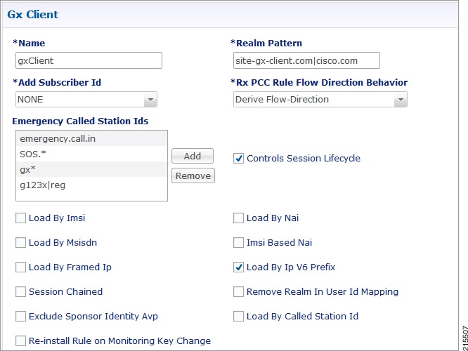 | ||
| Step 6 | Click
Add to configure the emergency APNs. The following
window is displayed.
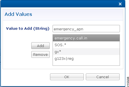 | ||
| Step 7 | Type the name of the emergency APN that you want to add in the Value to Add (String) text box and click Add. | ||
| Step 8 | Click
OK. In the example shown above, four APN entries are
already added.To remove an APN from this list, select the APN to be removed and
click Remove.
CPS supports wildcarding for the Emergency APN names. As shown in the example above, we have used '*' for wildcarding. CPS uses standard Java pattern characters for APN names. The pattern needs to follow the standard Java regular expression syntax described here. |
Configure Service for Emergency Sessions
For emergency APNs, the IMSI may not be present. Hence, CPS allows emergency sessions without subscriber authentication.
| Step 1 | Log into Policy Builder. |
| Step 2 | Select the Services tab. |
| Step 3 | From the left pane, select Domains. |
| Step 4 | Select the domain name that you want to use for emergency subscribers. Domain attributes open up in the right pane. To create a new Domain, refer Overview. |
| Step 5 | Select the Advanced Rules tab. |
| Step 6 | Click select near Anonymous Subscriber Service. |
| Step 7 | In the new window displayed, select the service that you want to assign for emergency sessions and click OK. |
Configure Prioritizing Emergency Sessions using APNs
Emergency calls are fast-tracked through the CPS platform by bypassing authorization logic. As a user, the CPS platform enables to prioritize these emergency calls by APN. CPS uses “Emergency Message Priority”, for this prioritization. These attributes are part of “Inbound Message Overload Handling” feature under “Diameter Configuration”. For more details, refer Inbound Message Overload Handling.
| Step 1 | Log into Policy Builder. | ||||||||||||||||||||||||||
| Step 2 | Select the Reference Data tab. | ||||||||||||||||||||||||||
| Step 3 | From the left pane, select Systems and expand your system name or cluster name. | ||||||||||||||||||||||||||
| Step 4 | Select and expand the Plugin Configurations. | ||||||||||||||||||||||||||
| Step 5 | Select Diameter Configuration. Diameter configuration screen appears in the right pane. | ||||||||||||||||||||||||||
| Step 6 | Check Inbound Message Overload Handling check box. | ||||||||||||||||||||||||||
| Step 7 | Click
Add under Message Handling Rules table.
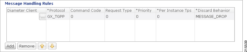 | ||||||||||||||||||||||||||
| Step 8 | Click
... in the
Diameter
Client column.
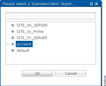 | ||||||||||||||||||||||||||
| Step 9 | Select the Gx Client in which we added the emergency APNs in Configure Diameter Gx Client for Emergency APNs and click OK. | ||||||||||||||||||||||||||
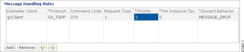
| Step 10 | Configure the
other parameters of the table.
|
RAN Congestion
Overview
Currently, when RAN congestion is configured, at the hour boundary there is a check for congestion level change. If the congestion level has changed then RAR is sent in which new rules corresponding to changed congestion level are applied.
The next evaluation time for session is set to the time when the congestion level changes next. At that hour boundary again the session is evaluated, and new rules applicable to changed level are applied. Since all the sessions are getting re-evaluated at applicable hour boundaries where the congestion level changes, there is a possibility of huge amount of RAR's being generated by CPS. CPS can generate this load of RARs without any issues as it is distributed among the CPS VMs. However, there might be limitation on other network elements to handle the RAR surge.
To prevent RAR burst at the hour boundary, evaluate configured services for the next hour based on the appropriate congestion levels. Also, preinstall the rules specifying Activation and Deactivation times.
Policy Builder Configuration
| Step 1 | Log into Policy Builder. |
| Step 2 | Select the Services tab, and then click . |
| Step 3 | Click Use Case Template link from the right side under Create Child to create a use case template for PreDefinedRuleBase. |
| Step 4 | Enter the name for use case template. For example, name the new template as PreDefinedRuleBase. |
| Step 5 | Select Actions tab. |
| Step 6 | Click Add to open Select Service Configuration. |
| Step 7 | Select
PreDefinedRuleBase and click required service
configuration parameters that need to be configured. Click
OK to add the service in Service Configuration pane.
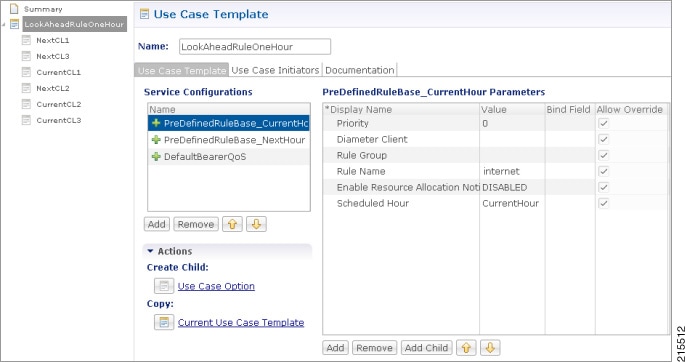 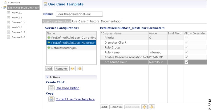
Example of configuration for one of the use case modifiers is shown below: 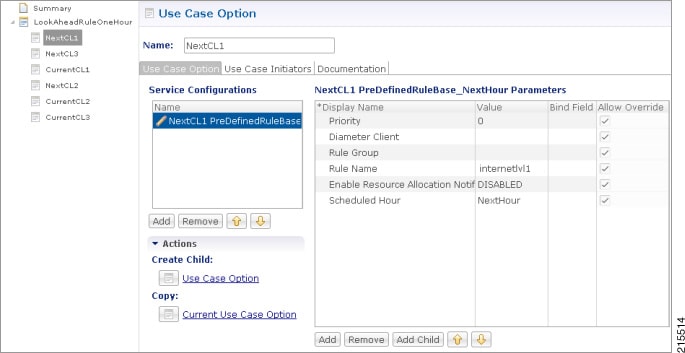 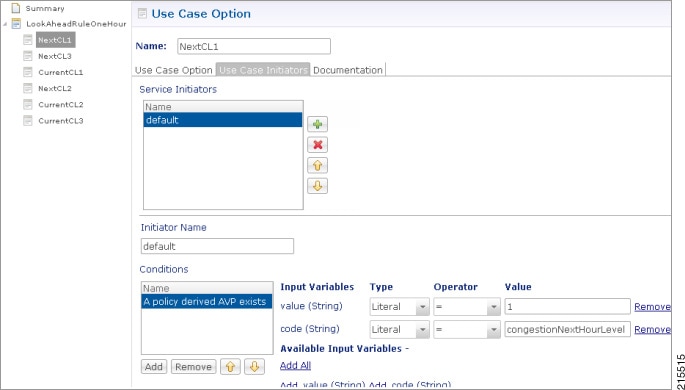 |
Control Center Configuration
Parameter Descriptions
The following table provides information related to RAN Congestion parameters:
|
Parameter |
Description |
|---|---|
|
Rule Name |
Any name which you want to give for rule name. |
|
Scheduled Hour: drop-down list with three values. |
Default: It turns OFF Hour Boundary RAR enhancement feature for look ahead rules installation at hour boundary and causes rules to behave in normal fashion of getting installed at hour boundary as applicable CurrentHour: For the current hour rule activation time will be current time, deactivation time will be next hour. NextHour: For the next hour rule activation time will be next hour, deactivation time will be next-next hour. |
Note | By default, CPS sets the next evaluation time as per the next change in congestion level. To configure CPS to do a forward lookup for multiple changes in congestion level, add the following parameter to qns.conf: -DcongDataLookAhead=true |
Usage Monitoring
Overview
CPS supports Usage-Monitoring over Diameter Gx interface with different Balance Code, Dosage and monitoring level. Usage monitoring key Identifies the usage monitoring control instance and is subscribed using Event-Trigger AVP = USAGE_REPORT.
CPS also supports time based Gx usage monitoring control and reporting based on as 3GPP 29.212 Rel 12 Sections 4.5.16 and 4.5.17. It supports the ability to configure a Gx usage monitoring key as volume, time or both.
Policy Builder Configuration
| Step 1 | Login to Policy Builder. |
| Step 2 | Select the Services tab, and then click . |
| Step 3 | Click
Use Case
Template link from the right side under
Create
Child to create a use case template for
TableDrivenCiscoQosGroupRule.
|
| Step 4 | In the left pane of the Services tab, click to create a service option and add the UsageMonitoringKey use case template. |
| Step 5 | In the left pane of the Services tab, click to create a service and add the configured UsageMonitoringKey use case template. |
Scheduled Usage Monitoring
To support scheduling, CPS uses Monitoring-Time AVP in Monitoring information. To use Monitoring-Time AVP CPS supports Usage Monitoring Congestion Handling (UMCH) feature on Gx. If the PCEF does not support UMCH feature, CPS uses the RAR message to request account balance usage details of the previous or older schedule. CPS will charge the account balance usage against the old schedule and further grants a new dosage value as per the new schedule.
CPS uses the next evaluation time set on the diameter session to trigger the RAR message for requesting the usage-report on schedule's time boundary. The current Usage-Monitoring information in the Gx session is added with monitoring schedules to grant and track the usage for the PCEF, based on current and adjacent schedules. It also provides support to bind different balance code to each schedule. CPS grants, reserves and charges the respective balance as per the usage monitoring schedule defined. CPS defines dosage on each schedule and accordingly grants single units to PCEF in Granted-Service-Units AVP. It also defines charging rate on each schedule. The default charging rate is 1.
This feature provides support to configure multiple schedules in monitoring-key service configuration.
Configure Scheduled Usage Monitoring
Scheduled Usage Monitoring is configured in the Service Options section of the Services tab. The Service Configuration UsageMonitoringKey allows scheduled monitoring in the Monitoring Schedule (List) parameter.
Before configuring a scheduled monitoring, the following configuration must be completed in the Policy Builder:
-
Configure the Account Balance Templates in the Reference Data tab as described in Account Balance Templates.
-
Configure a Use Case Template in the Services tab as described in Use Case Templates.
Configuration restrictions while defining Monitoring schedule in Policy Builder:
-
The time value should be entered in hh:mm format.
-
Monitoring schedule should be complete for 24 hours.
-
First monitoring schedule should start at midnight with start-time value as 00:00 and last schedule should end on next midnight with end-time value as 23:59.
-
Time entry with 23:59 will be rounded-up to complete the 24 hour schedule.
| Step 1 | Select the Services tab. |
| Step 2 | Click , and select the corresponding Service option whose name matches the Use Case Template. |
| Step 3 | Provide a name for the service in the Name field. |
| Step 4 | In the Service Configurations section, click Add. The Select Service Configuration dialog box is displayed. |
| Step 5 | Select
UsageMonitoringKey and click
OK.
For parameter descriptions under UsageMonitoringKey, refer to UsageMonitoringKey. |
| Step 6 | In the Service configuration parameters, select Monitoring Schedule and click Add Child to add a UsageMonitoringSchedule. |
| Step 7 | Select the UsageMonitoringSchedule to provide the values as shown in the example.
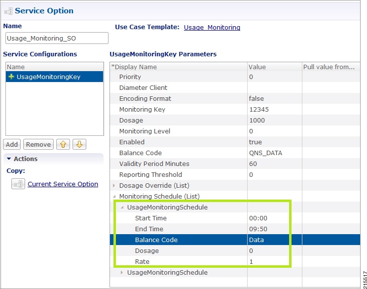
To add multiple UsageMonitoringSchedule, click Add Child and add the parameters according to your requirements. |
Time Usage Monitoring
CPS supports time based Gx usage monitoring control and reporting based on as 3GPP 29.212 Rel 12 Sections 4.5.16 and 4.5.17.
It supports the ability to configure a Gx usage monitoring key as volume, time or both.
Balance: This feature reuses the time related units like seconds, minutes, hours, and so on for balance that are already provided by Account Balance Templates. No new threshold types have been added. Only % thresholds can be used with Time balances.
Use Case Template: A new UsageMonitoringKeyDual service configuration has been added to support the time usage monitoring (The existing UsageMonitoringKey is still supported for Volume Usage monitoring). This new option provides a way to configure usage monitoring for both time and volume (independently as well as together under single monitoring key). To monitor usage under one key for Volume and Time, both the balance codes need to be provided in the Service Configuration. For independent monitoring, only the relevant type of fields can be set. For example, for only Volume monitoring, fields related to time monitoring can be left blank/null and vice versa. Multiple instances of UsageMonitoringKeyDual can also be included in the service configuration each corresponding to a unique monitoring key.
Gx Message Handling: The following new AVPs are now supported under this feature:
-
CC-Time (within Granted-Service-Unit and Used-Service-Unit)
-
Quota-Consumption-Time (within Usage-Monitoring-Information)
For configuration in Policy Builder, refer to Policy Builder Configuration.
Bandwidth Monitoring
Overview
The purpose of this feature is to track bandwidth and apply policies based on that. Normal usage monitoring is used to track usage but not bandwidth. This feature is based on usage monitoring key being installed in order to have the usage reported by the PCEF. Using this feature, the service provider can install a monitoring key and the different thresholds that are used to flag the subscriber. This feature works in parallel with the usage monitoring feature but the usage monitoring feature has a higher priority since that one is about charging traffic. In this context 'higher priority' means that usage monitoring feature installs any usage monitoring keys it needs to do its job.
Bandwidth monitoring installs any additional monitoring keys it needs while reusing any monitoring keys that were already installed. In order to reuse a monitoring key the same monitoring key name should be used in both BandwidthMonitor and UsageMonitoringKey objects. ReportingTimeout value is in minutes and is used to set the Revalidation-Time AVP so that the subscriber has a chance to get unthrottled before the allocated dosage is used. The BandwidthThreshold Lower Value is in kbps and when the computed bandwidth used is over that value, the corresponding Label is set to the subscriber for the particular application identified by Name attribute.
Policy Builder Configuration
| Step 1 | Log into Policy Builder. | ||
| Step 2 | Select the Services tab and then click Use Case Templates. | ||
| Step 3 | If you want to create a new use case template, click Use Case Template in the main window under Create Child to open the default use case template. | ||
| Step 4 | Enter the name for the template. For our example, name it as Bandwidth Monitoring. | ||
| Step 5 | Select Actions tab. | ||
| Step 6 | Click Add under Service Configurations to open the Select Service Configuration dialog box. | ||
| Step 7 | Select the
necessary service configuration objects and click
OK to add the objects in
Service
Configurations pane.
| ||
| Step 8 | Click . | ||
| Step 9 | Click Service Options in the main window under Create Child to open the Select Service Configuration dialog box, which contains already defined Service Configurations, and click OK. | ||
| Step 10 | Select
BandwidthMonitor from the
Service Configurations pane.
| ||
| Step 11 | Click . | ||
| Step 12 | Click Use Case Option in the main window under Create Child to open the Use Case Option pane and name it as Low Bandwidth Usage. | ||
| Step 13 | Click Add to open the Select Service Configuration dialog box, select DefaultBearerQoS and click OK to add the service. | ||
| Step 14 | Rename the configured service as LowDefaultBearerQoS. | ||
| Step 15 | Click Use Case Initiators tab. Click plus sign (+) to add a service initiator. Rename the initiator as Low. | ||
| Step 16 | Under
Conditions, click
Add to open the
Select
the Condition Phrase which you would like to use dialog box, select
the required condition and click
OK.
The added condition is displayed in Conditions pane. | ||
| Step 17 | Click Add All under Available Input Variables. | ||
| Step 18 | Create another initiator and add the condition A bandwidth monitor status does not exist to it. Add the name (String) to the condition. | ||
| Step 19 | Repeat the steps from Step 12 to Step 17 for Medium and High bandwidth usage. | ||
| Step 20 | Click provided in Step 4. Add all the service configurations. | ||
| Step 21 | Define the
different parameters for low, medium and high bandwidth usage monitoring in the
Service Configurations pane according to the
customer requirements. A sample configuration for Low Bandwidth Usage
Monitoring is shown below.
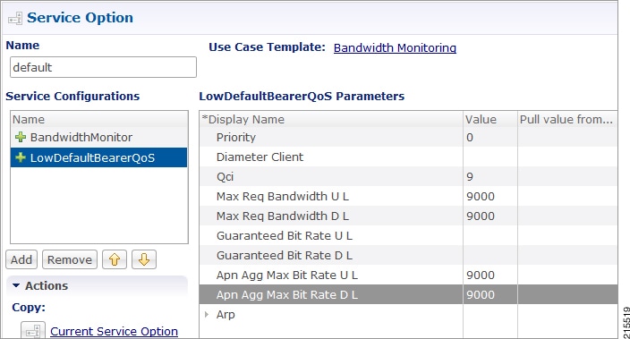 | ||
| Step 22 | Click , and the click Service under Create Child to open the Service dialog box. | ||
| Step 23 | Enter the name in Code and Name text fields. | ||
| Step 24 | Click Add to open the Select Service Configuration dialog box. Select the service that you configured in Step 4, and click OK. | ||
| Step 25 | Select Use V9 Event Trigger Mapping and Rel8 Usage Monitoring Supported under Diameter Configuration |
Parameter Descriptions
The following parameters can be configured in Bandwidth Monitoring:
|
Parameter |
Description |
|---|---|
|
Name |
Any name you can give. |
|
Reporting Timeout |
The revalidation timer for defined dosage. |
|
Lower Value |
The minimum bandwidth value that you can give for that particular Label. This value is not standard and defined as per requirement and should be an integer. |
|
Label |
The name of label, which can depend upon the user's requirement. |
Override Control AVP
Overview
CPS supports Override-Control specific AVPs in CCA-i and CCA-u responses to the PCEF on the Gx Interface and Gx RAR message. These AVPs are used to override charging parameters for predefined and static rules on the PCEF.
Policy Builder Configuration
| Step 1 | Log into Policy Builder. | ||||||||||||||||||||||||||||||||||||||||||||||||||||||||||||||||||||||||||||||||||||||||||||||||||||||||||||||||||||||||||||||||||||||||||||||||||||||||||||||||||||||||||||||||||
| Step 2 | Select the Services tab, and then click . | ||||||||||||||||||||||||||||||||||||||||||||||||||||||||||||||||||||||||||||||||||||||||||||||||||||||||||||||||||||||||||||||||||||||||||||||||||||||||||||||||||||||||||||||||||
| Step 3 | Click Use Case Template link from the right side under Create Child to create a use case template. | ||||||||||||||||||||||||||||||||||||||||||||||||||||||||||||||||||||||||||||||||||||||||||||||||||||||||||||||||||||||||||||||||||||||||||||||||||||||||||||||||||||||||||||||||||
| Step 4 | Enter the name for the template. For our example, name the new template as CiscoOverrideControl. | ||||||||||||||||||||||||||||||||||||||||||||||||||||||||||||||||||||||||||||||||||||||||||||||||||||||||||||||||||||||||||||||||||||||||||||||||||||||||||||||||||||||||||||||||||
| Step 5 | Select Actions tab. | ||||||||||||||||||||||||||||||||||||||||||||||||||||||||||||||||||||||||||||||||||||||||||||||||||||||||||||||||||||||||||||||||||||||||||||||||||||||||||||||||||||||||||||||||||
| Step 6 | In the newly created template, click Add under the Service Configurations pane. This will list all the service configuration objects available on the PCRF. Select the CiscoOverrideControl object from the gx section. | ||||||||||||||||||||||||||||||||||||||||||||||||||||||||||||||||||||||||||||||||||||||||||||||||||||||||||||||||||||||||||||||||||||||||||||||||||||||||||||||||||||||||||||||||||
| Step 7 | After selecting the necessary service configuration object, click OK to add the object in Service Configurations pane.
The following parameters can be configured for Override Control AVP.
AVP Structure in response/request message:
                        Override-Control
                        		*Override-Rule-Name
                        		Override-Charging-Action-Parameters
                        			Charging-Action-Name
                        			*Online-Charging-Action-Exclude-Rule
                        			Override-Charging-Parameters
                        			Override-Service-Identifier
                        				Override-Rating-Group
                        				Override-Reporting-Level
                        				Override-Online
                        				Override-Offline
                        				Override-Metering-Method
                        			Override-Policy-Parameters
                        				Override-QoS-Information
                        					Override-QoS-Class-Identifier
                        					Override-Max-Requested-Bandwidth-UL
                        					Override-Max-Requested-Bandwidth-DL
                        					Override-Guaranteed-Bitrate-UL
                        					Override-Guaranteed-Bitrate-DL
                        					Override-Allocation-Retention-Priority
                        						Override-Priority-Level
                        						Override-Pre-emption-Capability
                        						Override-Pre-emption-Vulnerability
| ||||||||||||||||||||||||||||||||||||||||||||||||||||||||||||||||||||||||||||||||||||||||||||||||||||||||||||||||||||||||||||||||||||||||||||||||||||||||||||||||||||||||||||||||||
Gx RAR Traffic
CPS is enhanced to support certain call flows and reduce Gx-RAR traffic towards PCEF as follows:
Gx CCR-U reports all Rx Charging-Rule as inactive in which case PCRF terminates the Rx Session and avoids sending Gx-RAR to remove rules already reported as inactive.
-
Gx CCR-U reports one or more Rx Charging Rule as inactive in which case PCRF would trigger a Rx RAR to PCSF which if responded with a DIAMETER_UNKNOWN_SESSION_ID (5002) terminates the Rx Session and avoids sending Gx RAR with Charging-Rule-Remove AVPS for rules already reported as inactive.
-
Gx CCR-U reports one or more Rx Charging Rule as inactive in which case PCRF would trigger a Rx RAR to PCSF which is responded with a DIAMETER_SUCCESS (2001). Any subsequent AAR-U with MCD/MSC flow status reported as removed, removes the corresponding Rx Charging-Rule and does not trigger a Gx RAR with Charging-Rule-Remove AVP.
Configuring Policies Based on Gx Events
This section covers the following topics:
Overview
CPS supports the ability to make policy decisions based on the following event triggers received over the Gx interface:
The policy decisions based on the above event triggers could be the following:
For Gx interface:
-
Switch the UE from ONLINE to OFFLINE or vice versa
-
Change the Charging-Rule-Base-Name of the UE
-
Change (add/delete) the Charging-Rule-Name (predefined) of the UE
-
Change (add/modify/delete) the Charging-Rule-Name (Dynamic) of the UE
-
Ability to retry the impacted rule, number of retries, and the unique retries between each retry
For Rx interface:
-
Initiate a tear down/removal of the IMS rule over Rx
-
Inform the Rx client of the impacted rule and the reason for impact
For Sy interface:
For Sd interface:
Policy Builder Configuration
The following procedure is an example of how to configure Policy Builder to use the ActionBasedOnGxEventTrigger service configuration object to make policy decisions based on event triggers and associated rule failure codes received over the Gx interface.
| Step 1 | Log into Policy Builder. | ||||||||||||||||||||||||||||||||
| Step 2 | Click . | ||||||||||||||||||||||||||||||||
| Step 3 | Click Search Table Group. | ||||||||||||||||||||||||||||||||
| Step 4 | Under Table
Search Initiators do the following to evaluate the CRD such that the condition
is always false and table is not evaluated every time on any event by the
policy engine:
| ||||||||||||||||||||||||||||||||
| Step 5 | Click the Custom Reference Data Table link. | ||||||||||||||||||||||||||||||||
| Step 6 | Under Columns,
click
Add and enter the following input and output values:
The input AVPs and their corresponding CRD input columns must be configured in the ActionBasedOnGxEventTrigger service configuration object. When CPS receives a Gx CCR message with the Charging-Rule-Report AVP or the Credit-Management-Status AVP, CPS performs a one-time query on this CRD table. A one-time query on this CRD is also performed when CPS receives Charging-Rule-Report AVP with ACTIVE_WITHOUT_CREDIT_CONTROL(10) for PCC-Rule-Status and Cisco-Event with Cisco-CC-Failure-Type. If the Remove-Rx-Rule AVP exists in the output with value = true, the following conditions can occur:
| ||||||||||||||||||||||||||||||||
| Step 7 | Select the Services tab, and then click . | ||||||||||||||||||||||||||||||||
| Step 8 | Click the Use Case Template link from the right side under Create Child to create a use case template. | ||||||||||||||||||||||||||||||||
| Step 9 | Enter the name for the template. In this example, name the new template as ActionBasedOnGxEventTrigger . | ||||||||||||||||||||||||||||||||
| Step 10 | Click the Actions tab. | ||||||||||||||||||||||||||||||||
| Step 11 | In the newly created template, click Add under the Service Configurations pane. This will list all the service configuration objects available on PCRF. Select the ActionBasedOnGxEventTrigger object under the gx section. | ||||||||||||||||||||||||||||||||
| Step 12 | Click
OK to add the object in
Service
Configurations pane. For the list of configurable parameters see
ActionBasedOnGxEventTrigger
The AVP Name must be the same as mentioned in the following table while defining parameter values for ActionBasedOnGxEventTrigger Service Configuration object. The Column values are referenced from example CRD table columns created in Step 6. The other values mentioned in the table are used for example purpose only.
For any Gx action, a generic output column can be added which can be used as an input to any other CRD table. | ||||||||||||||||||||||||||||||||
| Step 13 | Click
Use Case
Initiators and do the following so that the use case is true only
in the following conditions:
When CPS receives event trigger CREDIT_MANAGEMENT_SESSION_FAILURE:
When CPS receives event trigger CREDIT_MANAGEMENT_SESSION_FAILURE (46) and/or Cisco-Event with CREDIT-CONTROL-FAILURE (5):
| ||||||||||||||||||||||||||||||||
Common Parameters Used
The following table contains the common parameters that can be configured under all the sections mentioned in this chapter:
|
Parameter |
Description |
|---|---|
|
Qci |
The QoS class identifier identifies a set of IP-CAN specific QoS parameters that define QoS, excluding the applicable bitrates and ARP. It is applicable both for uplink and downlink direction. The QCI values 0, 10 – 255 are divided for usage as follows: |
|
Max Req Bandwidth UL |
It defines the maximum bit rate allowed for the uplink direction. |
|
Max Req Bandwidth DL |
It defines the maximum bit rate allowed for the downlink direction. |
|
Guaranteed Bit Rate UL |
It defines the guaranteed bit rate allowed for the uplink direction. |
|
Guaranteed Bit Rate DL |
It defines the guaranteed bit rate allowed for the downlink direction. |
|
Apn Agg Max Bit Rate UL |
It defines the total bandwidth usage for the uplink direction of non-GBR QCIs at the APN. |
|
Apn Agg Max Bit Rate DL |
It defines the total bandwidth usage for the downlink direction of non-GBR QCIs at the APN. |
|
Priority Level Values: 1 to 8 - assigned for services that are authorized to receive prioritized treatment within an operator domain. Values: 9 to 15 - Can be assigned to resources that are authorized by the home network and thus applicable when a UE is roaming. |
The priority level is used to decide whether a bearer establishment or modification request can be accepted or needs to be rejected in case of resource limitations (typically used for admission control of GBR traffic). The AVP can also be used to decide which existing bearers to pre-empt during resource limitations. The priority level defines the relative importance of a resource request. Values 1 to 15 are defined, with value 1 as the highest level of priority. |
|
Preemption Capability |
If it is provided within the QoS-Information AVP, the AVP defines whether a service data flow can get resources that were already assigned to another service data flow with a lower priority level. If it is provided within the Default-EPS-Bearer-QoS AVP, the AVP defines whether the default bearer can get resources that were already assigned to another bearer with a lower priority level.
|
|
Preemption Vulnerability |
If it is provided within the QoS-Information AVP, the AVP defines whether a service data flow can lose the resources assigned to it in order to admit a service data flow with higher priority level. If it is provided within the Default-EPS-Bearer-QoS AVP, the AVP defines whether the default bearer can lose the resources assigned to it in order to admit a pre-emption capable bearer with a higher priority level.
|
|
Monitoring Key |
Identifies a usage monitoring control instance. Any value can be given. |
|
Priority |
It is priority of the service option within the service. |
|
Diameter Client |
The client configuration is used to apply different policies based on PCEF type. This is optional parameter. |
|
Rule Group |
Rule Group is to classify rules at PCRF to change set of predefined rules based on policy. This is an optional parameter. |
|
Enable Resource Allocation Notification |
This is having two values Enabled and Disabled. Default value is disabled. |
|
Dual Stack Session |
This is having two values Enabled and Disabled. Default value is disabled. |
|
Framed I P Type |
It is having four options. Default option is ANY_ONE. |
|
ToD Schedule |
Identifies the schedule for rule activation and deactivation. |
Sd Services
Overview
The Sd reference point is located between the Policy and Charging Rules Function (PCRF) and the Traffic Detection Function (TDF). The Diameter session on Sd is established either at the request of the PCRF in case of solicited application reporting by initiating a (TSR - TDF Session Request) or at the request of the TDF by initiating an (CCR-I) in case of unsolicited application reporting. Session modifications may be initiated by either TDF or PCRF.
Solicited Application
For the solicited application reporting, the Sd reference point is used for:
-
Establishment and termination of TDF session between PCRF and TDF.
-
Provisioning of Application Detection and Control rules from the PCRF for the purpose of traffic detection and enforcement at the TDF.
-
Usage monitoring control of TDF session and of detected applications.
-
Reporting of the start and the stop of a detected application’s traffic and transfer of service data flow descriptions for detected applications, if deducible, from the TDF to the PCRF.
Unsolicited Application
For the unsolicited application reporting, the Sd reference point is used for:
-
Establishment and termination of TDF session between PCRF and TDF.
-
Reporting of the start and the stop of a detected application’s traffic.
-
Transfer of service data flow descriptions for detected applications, if deducible, and transfer of Application instance identifier, if service data flow descriptions are deducible, from the TDF to the PCRF.
As part of the IP-CAN Session Establishment or Modification procedure, in case of solicited application reporting with a TDF, the PCRF initiates a TDF Session Establishment with the selected TDF. The TDF is selected based on data received from the PCEF or a local configuration at the PCRF and or SPR data for the subscriber.
TDF Session Termination happens in any of the following cases:
Policy Builder Configuration
| Step 1 | Log into Policy Builder. |
| Step 2 | Select the Services tab, and then click Use Case Templates. Click Summary and select Use Case Template. |
| Step 3 | Click Actions tab. |
| Step 4 | Click Add to open the Select Service Configuration dialog box. |
| Step 5 | Select ADC-Predefined-Rule and click required service configuration parameters that need to be configured. Click OK to add the service in Service Configuration pane. |
| Step 6 | In the Services tab, click to create a service option and add the Use Case Template that you just configured. |
| Step 7 | In the Services tab, click to create a service and add the Use Case Template that you just configured. |
Common Parameters Used
The following table contains the common parameters configured for Sd Services:
|
Parameter |
Description |
|---|---|
|
Qci |
The QoS class identifier identifies a set of IP-CAN specific QoS parameters that define QoS, excluding the applicable bitrates and ARP. It is applicable both for uplink and downlink direction. The QCI values 0, 10 – 255 are divided for usage as follows: |
|
Max Req Bandwidth UL |
It defines the maximum bit rate allowed for the uplink direction. |
|
Max Req Bandwidth DL |
It defines the maximum bit rate allowed for the downlink direction. |
|
Guaranteed Bit Rate UL |
It defines the guaranteed bit rate allowed for the uplink direction. |
|
Guaranteed Bit Rate DL |
It defines the guaranteed bit rate allowed for the downlink direction. |
|
Apn Agg Max Bit Rate UL |
It defines the total bandwidth usage for the uplink direction of non-GBR QCIs at the APN. |
|
Apn Agg Max Bit Rate DL |
It defines the total bandwidth usage for the downlink direction of non-GBR QCIs at the APN. |
|
Priority Level Values: 1 to 8 - assigned for services that are authorized to receive prioritized treatment within an operator domain. Values: 9 to 15 - Can be assigned to resources that are authorized by the home network and thus applicable when a UE is roaming. |
The priority level is used to decide whether a bearer establishment or modification request can be accepted or needs to be rejected in case of resource limitations (typically used for admission control of GBR traffic). The AVP can also be used to decide which existing bearers to pre-empt during resource limitations. The priority level defines the relative importance of a resource request. Values 1 to 15 are defined, with value 1 as the highest level of priority. |
|
Preemption Capability |
If it is provided within the QoS-Information AVP, the AVP defines whether a service data flow can get resources that were already assigned to another service data flow with a lower priority level. If it is provided within the Default-EPS-Bearer-QoS AVP, the AVP defines whether the default bearer can get resources that were already assigned to another bearer with a lower priority level.
|
|
Preemption Vulnerability |
If it is provided within the QoS-Information AVP, the AVP defines whether a service data flow can lose the resources assigned to it in order to admit a service data flow with higher priority level. If it is provided within the Default-EPS-Bearer-QoS AVP, the AVP defines whether the default bearer can lose the resources assigned to it in order to admit a preemption capable bearer with a higher priority level.
|
|
Monitoring Key |
Identifies a usage monitoring control instance. Any value can be given. |
|
Priority |
It is priority of the service option within the service. |
|
Diameter Client |
The client configuration is used to apply different policies based on PCEF type. This is optional parameter. |
|
Rule Group |
Rule Group is to classify rules at PCRF to change set of predefined rules based on policy. This is an optional parameter. |
|
Flow Status |
Defines whether the service data flow is enabled or disabled. |
|
Redirect Address Type |
Defines the address type of the address given in the Redirect-Server-Address AVP. |
|
Redirect Support |
This value indicates that redirection is enabled for a detected application's traffic. |
|
Redirect Server Address |
This value indicates the target for redirected application traffic. |
|
Event-Trigger |
This is not to re-request rules. Primarily to notify start/stop of applications or report usage. |
|
Parameter |
Description |
|---|---|
|
Tdf Application Identifier |
This references the application detection filter (for example, its value may represent an application such as a list of URLs, etc.), which the PCC rule for application detection and control in the PCEF applies. |
|
Mute Notification |
An indication whether application start/stop notification is to be muted for ADC Rule by the TDF. |
 Feedback