Overview
This guide provides step-by-step instructions on how to physically install and power up the Cisco 3375 Appliance for Cisco Connected Mobile Experiences. Details on running the automatic installation script is also provided.
This chapter contains the following sections:
External Features
This topic shows the external features of the Cisco 3375 Appliance for Cisco Connected Mobile Experiences.
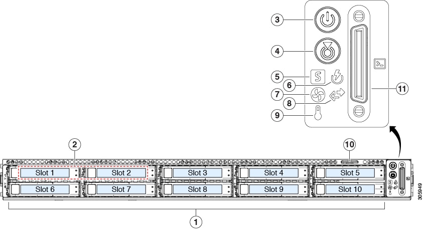
Cisco CMX 3375 appliance (SFF Drives) Front Panel Features
The following figure shows the front panel features of the small form-factor drive versions of the Cisco CMX 3375 appliance.
For definitions of LED states, see Front-Panel LEDs.
|
1 |
Drive bays 1 – 10 support SAS/SATA hard disk drives (HDDs) and solid state drives (SSDs) |
7 |
Fan status LED |
|
2 |
Drive bays 1 and 2 support SAS/SATA and NVMe PCIe solid state drives (SSDs) |
8 |
Network link activity LED |
|
3 |
Power button/power status LED |
9 |
Temperature status LED |
|
4 |
Unit identification button/LED |
10 |
Pull-out asset tag |
|
5 |
System status LED |
11 |
KVM connector (used with KVM cable that provides one DB-15 VGA, one DB-9 serial, and two USB connectors) |
|
6 |
Power supply status LED |
- |
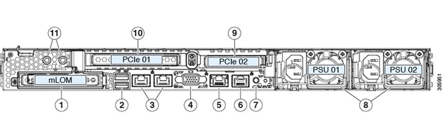
Cisco CMX 3375 appliance Rear Panel Features
The rear panel features are the same for all versions of the Cisco CMX 3375 appliance.
For definitions of LED states, see Rear-Panel LEDs.
|
1 |
Modular LAN-on-motherboard (mLOM) card bay (x16 PCIe lane) |
7 |
Rear unit identification button/LED |
|
2 |
USB 3.0 ports (two) |
8 |
Power supplies (two, redundant as 1+1) |
|
3 |
Dual 1-Gb/10-Gb Ethernet ports (LAN1 and LAN2) The dual LAN ports can support 1 Gbps and 10 Gbps, depending on the link partner capability. |
9 |
PCIe riser 2/slot 2 (x16 lane) Includes PCIe cable connectors for front-loading NVMe SSDs (x8 lane) |
|
4 |
VGA video port (DB-15 connector) |
10 |
PCIe riser 1/slot 1 (x16 lane) |
|
5 |
1-Gb Ethernet dedicated management port |
11 |
Threaded holes for dual-hole grounding lug |
|
6 |
Serial port (RJ-45 connector) |
- |
Status LEDs and Buttons
This section describes the location and meaning of LEDs and buttons and includes the following topics:
Front-Panel LEDs
|
LED Name |
States |
|||
|
1 SAS |
SAS/SATA drive fault
|
|
||
|
2 SAS |
SAS/SATA drive activity LED |
|
||
|
1 NVMe |
NVMe SSD drive fault
|
|
||
|
2 NVMe |
NVMe SSD activity |
|
||
|
3 |
Power button/LED |
|
||
|
4 |
Unit identification |
|
||
|
5 |
System health |
|
||
|
6 |
Power supply status |
|
||
|
7 |
Fan status |
|
||
|
8 |
Network link activity |
|
||
|
9 |
Temperature status |
|
Rear-Panel LEDs
|
LED Name |
States |
|
|
1 |
1-Gb/10-Gb Ethernet link speed (on both LAN1 and LAN2) |
|
|
2 |
1-Gb/10-Gb Ethernet link status (on both LAN1 and LAN2) |
|
|
3 |
1-Gb Ethernet dedicated management link speed |
|
|
4 |
1-Gb Ethernet dedicated management link status |
|
|
5 |
Rear unit identification |
|
|
6 |
Power supply status (one LED each power supply unit) |
AC power supplies:
|
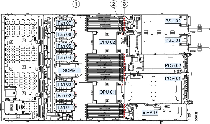
Internal Diagnostic LEDs
The Cisco CMX 3375 appliance has internal fault LEDs for CPUs, DIMMs, and fan modules.
|
1 |
Fan module fault LEDs (one behind each fan connector on the motherboard)
|
3 |
DIMM fault LEDs (one behind each DIMM socket on the motherboard) These LEDs operate only when the server is in standby power mode.
|
|
2 |
CPU fault LEDs (one behind each CPU socket on the motherboard). These LEDs operate only when the server is in standby power mode.
|
- |
General Warnings, Regulatory and Safety
Conventions
Safety warnings appear throughout this guide in procedures that may harm you if performed incorrectly. A warning symbol precedes each warning statement. Specific warnings are included in the sections to which they apply.
 Warning |
This warning symbol means danger. You are in a situation that could cause bodily injury. Before you work on any equipment, be aware of the hazards involved with electrical circuitry and be familiar with standard practices for preventing accidents. Use the statement number provided at the end of each warning to locate its translation in the translated safety warnings that accompanied this device. Statement 1071 SAVE THESE INSTRUCTIONS |
 Caution |
Means reader be careful. In this situation, you might do something that could result in equipment damage or loss of data. |
Warnings
The warnings below are general warnings that are applicable to the entire guide. Specific warnings are included in the sections to which they apply.
Warning |
There is the danger of explosion if the battery is replaced incorrectly. Replace the battery only with the same or equivalent type recommended by the manufacturer. Dispose of used batteries according to the manufacturer’s instructions. Statement 1015 |
Warning |
This equipment must be grounded. Never defeat the ground conductor or operate the equipment in the absence of a suitably installed ground conductor. Contact the appropriate electrical inspection authority or an electrician if you are uncertain that suitable grounding is available. Statement 1024 |
Warning |
Read the installation instructions before connecting the system to the power source. Statement 1004 |
Warning |
Only trained and qualified personnel should be allowed to install, replace, or service this equipment. Statement 1030 |
Warning |
Ultimate disposal of this product should be handled according to all national laws and regulations. Statement 1040 |
Regulatory and Safety
 Note |
Refer to for translated safety information for the Cisco CMX 3375 appliance. |
Note |
Refer to for regulatory information for the Cisco CMX 3375 appliance. |
 Feedback