Introduction
The IOS XE based Cisco Cloud Wireless LAN Controller sets the standard for Infrastructure as a Service (IaaS) secure wireless network services with maximum performance in the Amazon Web Services (AWS) cloud, bringing the world's most popular networking wireless platform to AWS.
Cisco Cloud Wireless LAN Controller (C9800-CL) combines the advantages and flexibility of AWS public cloud with the customization and features richness customers usually get with on-Prem deployments. The Catalyst 9800 is the first Wireless Controller deployed on AWS GovCloud.
In the first release the C9800-CL scales up to 3000 APs and 32000 clients with all enterprise grade differentiating features like Zero Touch AP provisioning, High Availability, Application Visibility & Control, and more. All this at ZERO cost software.
This Deployment Guide describes how to deploy the C9800 Wireless Controller in the AWS Public Cloud. It gives a brief introduction to the Public Cloud and the possible Service models available. It touches on the key Cloud Networking constructs and covers the Managed VPN deployment model and what is supported at FCS. Then describes the steps required to:
-
Create a VPN connection from the on-premise router to the VPC in AWS cloud
-
Launch a C9800-CL instance in AWS using the CloudFormation template
-
Launch an C9800-CL instance directly from the Amazon Machine Image (AMI).
Restrictions
With CSCwd31523, provisioning a Cisco Catalyst 9800 Series Wireless Controller using Cisco Catalyst Center is only possible on private cloud platforms. Provisioning on public cloud platforms such as AWS or Azure fails due to limitations in VLAN configurations.
Public Cloud overview
Today cloud computing is considered a key ingredient of any digital transformation strategy; many Enterprises have already embraced the public cloud as a strategy to innovate and differentiate from competitors. But what does “embracing the public cloud” really mean? Let’s start with clarifying this basic aspect.
Public Cloud Service models
According to The National Institute of Standards and Technology (NIST) Special Publication 800-145, there are three cloud service models commonly available:
-
Software as a Service (SaaS)
-
Platform as a Service (PaaS)
-
Infrastructure as a Service (IaaS)
Figure below shows a representation of the service models, highlighting the most important stack components and the areas of responsibility between the cloud provider and the consumer, the customer that is using these services.
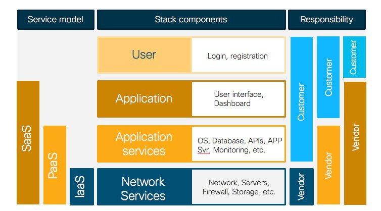
The SaaS model provides the highest level of abstraction and simplification. The whole “service” stack, from the infrastructure to the application level, is provided by the cloud service provider. As the customer, you directly access the service through user web interface or an application programming interface (API). On the other side, the consumer does not manage or control the underlying cloud infrastructure. Cisco Meraki leverages this model
In the PaaS model, the cloud service provider provides all the components of the platform needed to run your own applications. This includes the underlying cloud infrastructure networking and security plus additional services like databases and monitoring tools.
Finally, the IaaS model provides the computing resources, the storage and networking components (e.g., routers, firewalls, etc.) and leaves the customer to deploy their applications and services. This model gives the customer the highest level of control and flexibility but some integration work is required. The IaaS model is the one chosen for the Catalyst 9800 Wireless Controller on Cloud
Cisco Catalyst 9800 Wireless Controller as IaaS
The Public Cloud model chosen for the Cisco Catalyst 9800 for Cloud is the Infrastructure as a Service (IaaS) one. This means that the customer can rely on the Public Cloud vendor to provide the networking, the computing and the security infrastructure, but then the C9800 will be fully managed and controller by the customer as a virtual machine in the cloud.
There are two main reasons why customers should look at deploying C9800 in the cloud with an IaaS model:
-
Exploiting the advantages of the Public Cloud
-
Retaining the customization and control they usually have with controller onPrem
There are many advantages in adopting the Public Cloud, let’s list the one that are most significant for the C9800:
-
Agility: it takes few minutes to spawn a C9800 instance in AWS; it becomes extremely easy to launch a wireless controller to test some new feature or functionality and terminate it when done.
-
Scalability: there are no physical limits in the public Cloud, so you add new instance as the requirements for additional APs or clients increase
-
Global footprint: this is important for latency but also for security and privacy policies. The Public Cloud providers have a global footprint so from any location you install APs you can reach a C9800-CL in the cloud in less than 50 ms. Some customers have a strict security policy dictating that user data and traffic need to stay within the region; the public cloud providers have a Data Center in every geographical region
-
Cost effectiveness: reduce data center footprint and infrastructure costs. Shift from a capital expenditure (buying up front) model to an operational expenditure (pay-as-you-go) model
At the same time, the customer will have full control on the configuration of the Catalyst Wireless controller: what software image to run, what functionalities to turn on or off, what configuration tweaks to apply. On this aspect, there is no difference from deploying a wireless controller onPrem.
Using an IaaS model and deploying and manage your own instance in the cloud, it means that more work is on the customer to integrate the C9800 with the cloud infrastructure. Let’s introduce some important cloud networking concepts and then describe how to deploy C9800-CL in AWS.
Public Cloud networking
I order to deploy C9800-CL in the Public Cloud you need to get familiar with some new concepts like Regions, Availability Zones, VPC, etc. The intent of this guide is to provide a quick intro and leave the user to double click on these concepts using the available AWS documentation.
When first logging in the AWS console (https://console.aws.amazon.com) you would first want to select the Region where your instance will be installed. A Region is a distributed Data Center location across the globe. Each Region is independent and separated. AWS has 15 different Regions available in all part of the world (remember the global footprint advantage?) as shown below:
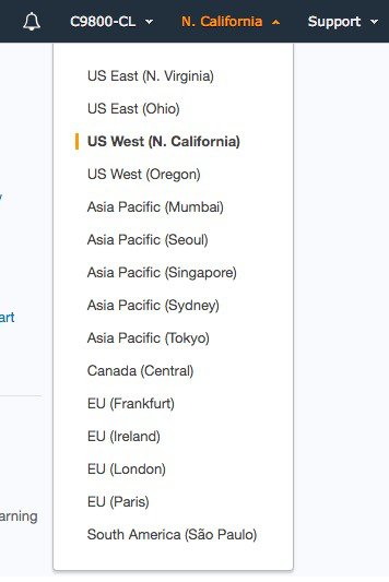
The user would pick the one closest to the locations where APs will be deployed.
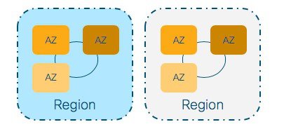
Within the region you have Availability Zones. These are fault-tolerant areas within a Region and they are all interconnected. When you launch an instance, you can select an Availability Zone or let AWS choose one for you. Here is a simple Region – Availability Zone visualization:
Another important concept is the Virtual Private Cloud (VPC). This represents your private network in the cloud, it’s an extension of your onPrem network to the Cloud. There is a default VPC in every region and to deploy your C9800-CL you can use the default VPC or create a custom one. Creating a custom VPC allow you to define all the networking aspects: subnets, gateways, security groups, etc. So, it gives you total flexibility.
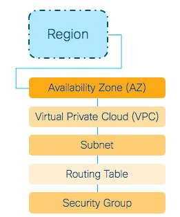
After you have defined a VPC, you can create subnets within the VPC, define routes to and from these networks and also specify the security rules to access your instances in the VPC. Again, this is your private network in the public Cloud. To know more about VPC please refer to AWS documentation:
https://docs.aws.amazon.com/vpc/latest/userguide/getting-started-ipv4.html
Public Cloud deployment mode for the Catalyst 9800
Once the C9800-CL is created in a VPC, we need to established a connection between the cloud instance and the APs on Prem. This can be done in two ways:
-
Creating a Virtual Private Network (VPN) between the AP locations and the Public Cloud
-
Leveraging Internet and a Public IP address to reach the Wireless Controller in the Cloud
Initially, the only deployment model supported for C9800-CL on AWS cloud is the Managed VPN.
Note regarding the public IP model: while joining APs using the Public IP is not supported, the customer may decide to assign the C9800-CL instance a Public IP for ease of Management. At FCS this is not officially supported and it’s the customer responsibility to properly configure the VPC with a default route to the internet gateway and a security group to block all CAPWAP traffic from reaching the C9800-CL controller through the public IP.
The Managed VPN deployment mode
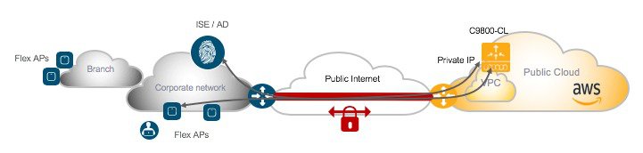
In this first release (16.10), Cisco Cloud Wireless LAN Controller supports the following deployment scenario: the C9800-CL is available in AWS Virtual Private Network (VPC) connected to the customer enterprise network via a managed VPN. The VPN can be terminated either on the AWS Gateway Router or on an AWS based router of customer choice (like the Cisco CSR Cloud router).
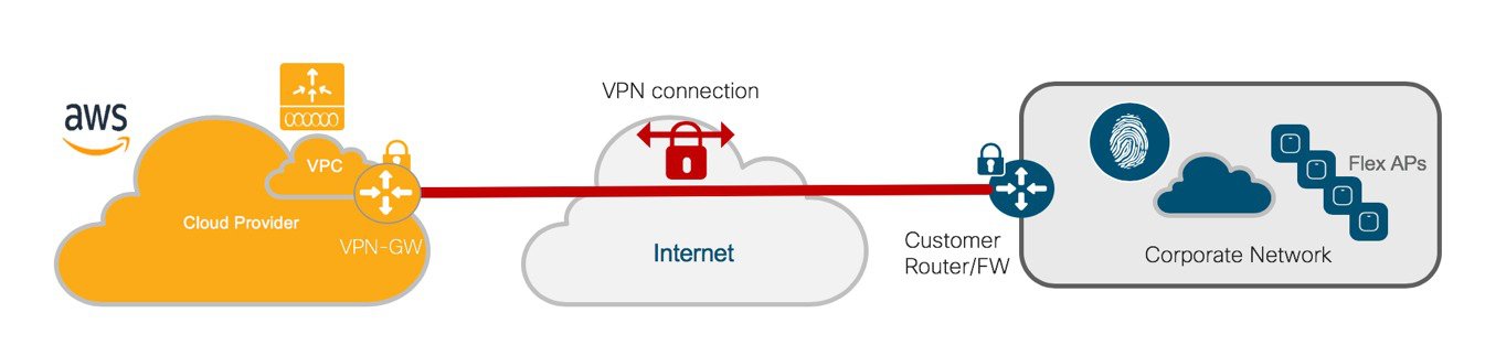
The VPN tunnel can be established from the corporate DC and all the AP locations leverage this connection to reach the C9800-CL or each AP location (branches, for example) would have to established a VPN tunnel to the Cloud.
As explained in the next session, establishing a VPN tunnel to the AWS provided VPN gateway is extremely easy. But it comes with some limitations: it only supports 10 remote VPN connections and it only supports IPSEC tunnels.
If you want more options for VPN (IPSec, DMVPN, FlexVPN, GETVPN, EZVPN) and larger scale, the Cisco CSRv router can be used as a VPN termination alternative. More info here: https://www.cisco.com/c/en/us/td/docs/routers/csr1000/software/aws/b_csraws.html
Once the tunnel is established, the C9800-CL will get an IP address in a private subnet in the VPC and subnet would need to be routed to the onPrem networks where the AP resides. As we said, the VPC is just an extension of your onPrem network and proper routing would needs to be established. Here is a simple example:

Here the VPC subnet is 10.10.10.0/24 and it routed through the VPN-GW to reach the AP subnet (10.100.0.0/24). Some important cloud networking considerations:
-
All interfaces in Public Cloud are Layer 3, there is no concept of trunk interfaces
-
In Public Cloud IP: customer can configure a static IP to allocate to the controller instance
-
For Catalyst 9800 Cloud Wireless Controller in AWS only one interface deployment is supported: this means that the Device Management/Service interface and Wireless Management interface are same
-
At FCS customer may experience longer than usual download time (30-40 mins for W2 APs) when the AP joins the FIRST time (and first time only). This is due to the reduced MTU introduced by the VPN tunnel
AP deployment mode with Public Cloud
Since we are deploying an instance of the wireless controller in the public cloud, it makes sense to keep the client traffic local to the site where the APs are located. Also, the latency introduced by the public Internet needs to be considered when deciding the AP mode of operations.
For these reasons, the only AP deployment mode supported for C9800-CL in AWS Cloud is Flex Central Authentication and Local Switching for IPv4 and IPv6 clients, with fall back to Local Authentication if the link to the cloud controller would become not available.
The AAA server is assumed to be on premise and that’s the configuration that has been tested and hence supported.
This means that the following high-level traffic flow would take place for client full authentication:
-
EAP traffic is received by AP and sent to WLC
-
WLC talks Radius to ISE/AAA
-
ISE replies with authentication result
-
WLC sends the reply to AP
-
AP relays authentication frames to client
-
Traffic is locally switched at AP
If fast roaming is supported (802.11r for example), this exchange will happen only the first time the client authenticates to the network. Every subsequent roaming will be handled locally at the AP without the need to contact the AAA server.
If device only supports slow roam, then the flow described above will take place at each roam.
 Note |
Since this is a FlexConnect deployment the same WAN/Internet recommendations and requirements would apply. Please refer to the Flex Deployment guide for more details: https://www.cisco.com/c/en/us/td/docs/wireless/controller/technotes/8-7/Flex_7500_DG.html#pgfId-43317 |
High Availability for C9800-CL on Public Cloud
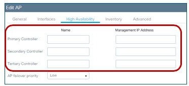
The supported high availability (HA) for C9800-CL in public cloud is the N+1 availability where user defines a Primary, secondary and optionally a Tertiary controller for APs to register to.
Since all SSIDs are configured with FlexConnect Local switching, N+1 HA guarantees no network downtime upon Primary controller failure: APs will transition to standalone mode keeping the existing client connections and then will join the Secondary Controller.
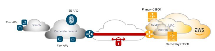
It is recommended to instantiate the Secondary controller in a separated availability zones for redundancy; this can be done by deploying it in a different subnet and assign the subnet in a different availability zone. Then you would need to configure the Primary/Secondary for the APs.
This can be done at a location level using the site tag and the join profile setting within the site tag:
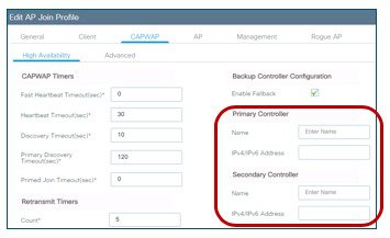
Or it can be configured directly on the AP and in this case, there is an option to define the Tertiary controller as well:
Managing the C9800-CL on Public Cloud
The Cisco Catalyst 9800 Wireless Controller can be managed both via the integrated Web Graphical User Interface (GUI) and via the Programmatic interfaces.
The GUI has a DAY 0 interface to ease the initial setup of the box and an intuitive DAY 1 interface for all the other possible configurations. Catalyst 9800 Wireless controller has two guided configuration work flow:
-
Basic: this is an intent based configuration flow where the user is abstracted from any configuration details and guided through the creation of a remote or local site in three simple steps.
-
Advanced: guided workflow to configure all the relevant configuration constructs (Profiles and Tags)
Out of the box the C9800-CL supports a NETCONF interface to allow the customer to manage via standard. YANG data models define the data that is available for configuration and streaming telemetry. For more information about Programmability for the Catalyst 9800 series, please refer to the related deployment guide.
Launching Catalyst 9800 Wireless Controller on AWS Cloud
Information about launching Cisco Catalyst 9800 on AWS
Launching a Cisco Catalyst 9800 Amazon Machine Image (AMI) occurs directly from the AWS Marketplace. Cisco Catalyst 9800 will be deployed on an Amazon EC2 instance in an Amazon VPC instance.
Supported AMI type and scale
For the first release of the Cisco Catalyst 9800 Wireless Controller on cloud, Cisco will support the following Instance types:
-
C5.xlarge: 4 vCPUs, 8 GB RAM, 8GB Disk with 1 vNIC
The allocated resources will allow the instance to scale to 1,000 APs and 10,000 clients.
Licensing
The Cisco Catalyst 9800 Wireless Controller for AWS is purchased and launched as an Amazon Machine Image (AMI) on AWS Marketplace using the Bring Your Own License (BYOL) AMI model. After you deploy the C9800-CL in AWS you would have to purchase the DNA subscription licenses for APs using the Smart Licensing model.
For a more detailed overview on Cisco Licensing, go to cisco.com/go/licensingguide.
Encrypted Elastic Block Storage (EBS)
When you launch a Cisco Catalyst 9800 from AWS marketplace, you cannot select encrypted Elastic Block Storage (EBS). However, you can follow the procedure to create an AMI with Encrypted Elastic Block Storage. This process is summarized below:
-
Create a Cisco Catalyst 9800 instance from the AWS marketplace
-
Take a snapshot of this Cisco Catalyst 9800 instance
-
Create a private AMI based on the snapshot
-
Copy the private AMI to a new AMI and select "Encrypt target EBS snapshots"
Different ways to launch a Cisco Wireless 9800 instance in AWS cloud
At FCS, the customer has three different ways to spin up a C9800-CL in the AWS public Cloud:
-
Launching a C9800-CL instance from AWS Marketplace using a CloudFormation Template
-
Launching a C9800-CL instance from AWS Marketplace using the AMI
-
Launching a C9800-CL instance from the AWS console
The process varies from a more manual procedure, where he customer has control of each configuration parameter (via AWS console), to a completely guided flow (using the CloudFormation template); this gives the customers the possibility to choose the best option that fits their requirements.
As described earlier, at FCS, Cisco only supports Managed VPN as the deployment mode for the new controller in the cloud: this means that a VPN tunnel has to be stabled between the on-premise location/s with APs and the customer VPC in the AWS cloud.
So, let’s first describe the required steps to create this VPN tunnel before we illustrate the procedures to launch a Catalyst 9800 Wireless Controller in the AWS public Cloud.
Establishing a VPN connection using the AWS VPN router
As described earlier, at FCS Cisco only supports deploying the C9800 in the AWS Cloud leveraging the Managed VPN deployment mode.
Prerequisites
A VPC should have already been created, or the default VPC can be used. For more info on how to setup a VPC please read here: https://docs.aws.amazon.com/vpc/latest/userguide/getting-started-ipv4.html
Creating a VPN connection from the enterprise router to the AWS gateway
Follow the steps to create a VPN connection from the enterprise router to the AWS gateway in your VPC:
Procedure
|
Step 1 |
Login in AWS console and go to the VPC dashboard |
||
|
Step 2 |
In the left menu, go to VPN Connections > Customer Gateways |
||
|
Step 3 |
Click on “create customer gateway” |
||
|
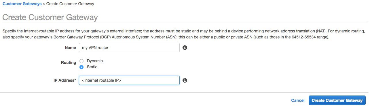
Step 4 |
The window below appears. Enter a name for your VPN router, choose if you want dynamic or static routing for this VPN and then provide the external, internet routable address of your router/firewall. Click on “create customer gateway”
|
||
|
Step 5 |
Next create an AWS virtual private gateway. On the VPC dashboard go to VPN Connections > Virtual Private Gateway and click on “create Virtual Private Gateway” |
||
|
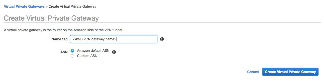
Step 6 |
The window below appears. Enter a name (this will be the AWS VPN router name). You can choose an ASN or just leave the default picked by Amazon.
|
||
|
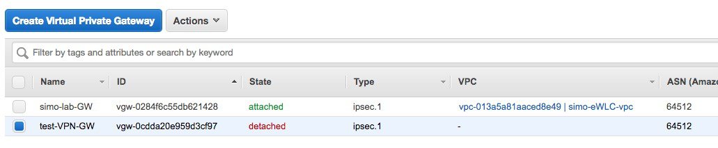
Step 7 |
Once created the status of the AWS VPN gateway is shown as “detached” as you need to attach it to the VPC.
|
||
|
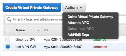
Step 8 |
Click on Actions and choose “Attach to VPC”.
|
||
|
Step 9 |
In the pop-up window select the VPC.
|
||
|
Step 10 |
At this point you have defined both the customer gateway and the AWS VPN gateway, now it’s time to create the VPN connection. In the VPC dashboard, go to VPN Connections > VPN Connections and click on “create VPN connection” |
||
|
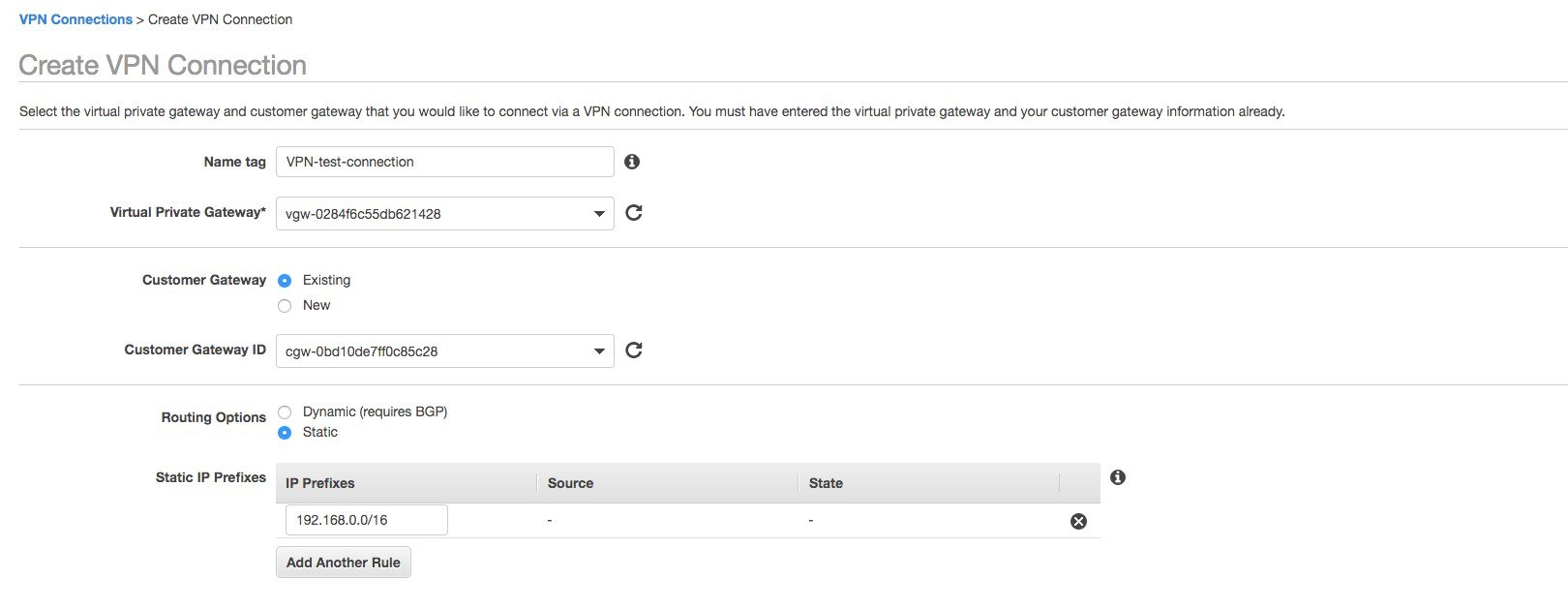
Step 11 |
A popup windows appears, you need to fill in all the information: name of the VPN connection (just a name), select the AWS VPN gateway created in the previous steps 5 to 9; for customer gateway select the one we configured initially in step 4. Select the routing options that you will be using to exchange routes. In this example, to keep it simple, we have selected static. Configure the remote subnets reachable through the VPN. This would be the remote network where your APs will be on-prem.
|
||
|
Step 12 |
Optionally you can assign the subnet and keys for the tunnel interfaces for the IPSEC VPN. AWS will create always two tunnel interfaces for redundancy. You can also leave it blank and AWS will choose these settings automatically. 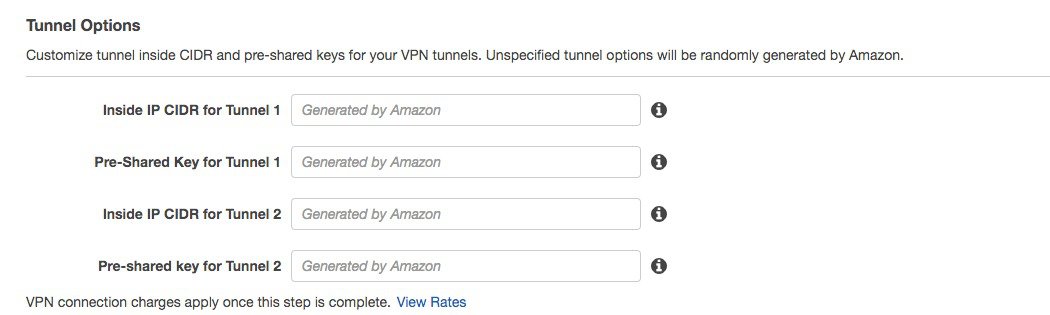 |
||
|
Step 13 |
Click on “Create VPN Connection”. You will see a message saying that the “Create VPN Connection Request Succeed”. |
||
|
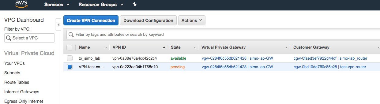
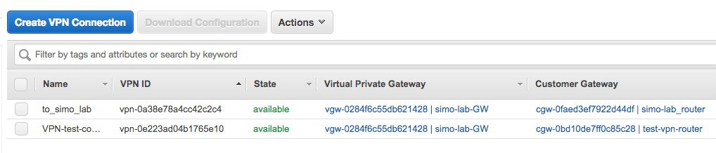
Step 14 |
It will take few minutes for the connection to set up and go from status “pending”….
to available:
|
||
|
Step 15 |
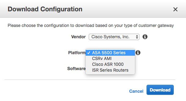
While in pending state, you can already download the configuration to deploy on the on-premise VPN router, your router. Click on the “Download Configuration” button. In the popup window select the brand and type of the customer VPN router/firewall.
Click on Download to download the file on your computer. This file contains all the commands you need to setup the VPN connection. You would need to modify the route by entering the remote subnets you have chosen for your VPC and then paste it in your router/firewall.
|
||
|
Step 16 |
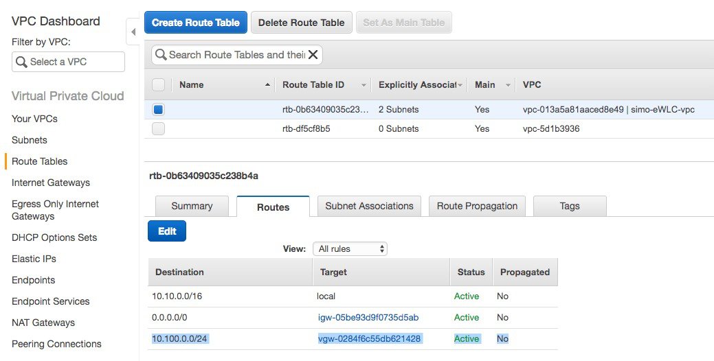
Make sure that you have a route in your VPC to reach the remote subnet pointing to the VPN gateway. In the example below the remote subnet is 10.100.0.0/24
|

Launching a C9800-CL from AWS Marketplace with CloudFormation template
This is the easiest way of spinning up a C9800-CL instance in AWS, so let’s cover this first.
Prerequisites
-
A Managed VPN connection is created from the corporate network to the VPC
-
A VPC is created with the desired subnet for the C9800 Wireless Management interface
-
The C9800 CloudFormation template. The customer will not need to deal with the CloudFormation template as this is automatically integrated in the launching procedure; if desired, the customer can download and view the CloudFormation template file from the AWS Market Place page of the product.
-
Amazon Machine Instance ID (AMI-ID) for the desired 9800 software release; the AMI will be available in AWS market place.
-
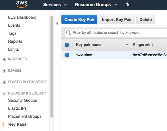
If you don’t have one already, create a key pair by going to EC2 dashboard > Network & Security > Key pairs and click on “Create Key Pair”
Steps to Launch a C9800-CL from AWS Marketplace with CloudFormation Template
Procedure
|
Step 1 |
Sign in AWS Marketplace: https://aws.amazon.com/marketplace/
|
||
|
Step 2 |
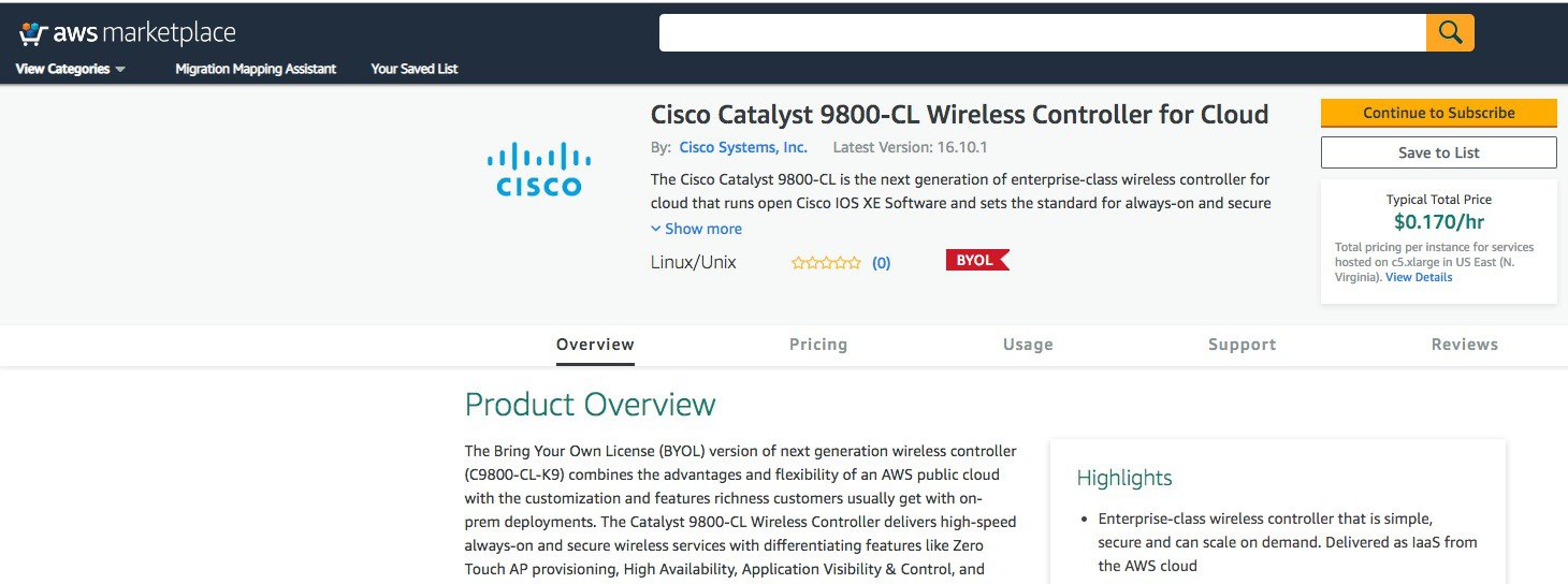
Search for Catalyst 9800 or C9800-CL and from the search results, click the Cisco Catalyst 9800-CL Wireless Controller for Cloud page.
|
||
|
Step 3 |
The product overview page displays information about the product, support, and licensing, and an estimated cost of deploying the C9800-CL in the different AWS regions.
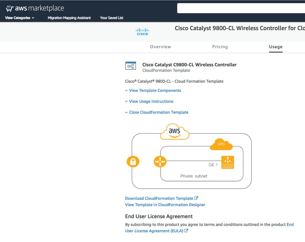
As you scroll down the page, you see information about the topology and the CloudFormation template.
Click Download CloudFormation Template if you want to look at the file. (You can open the file with any notepad type of program.) |
||
|
Step 4 |
Click Continue to Subscribe. 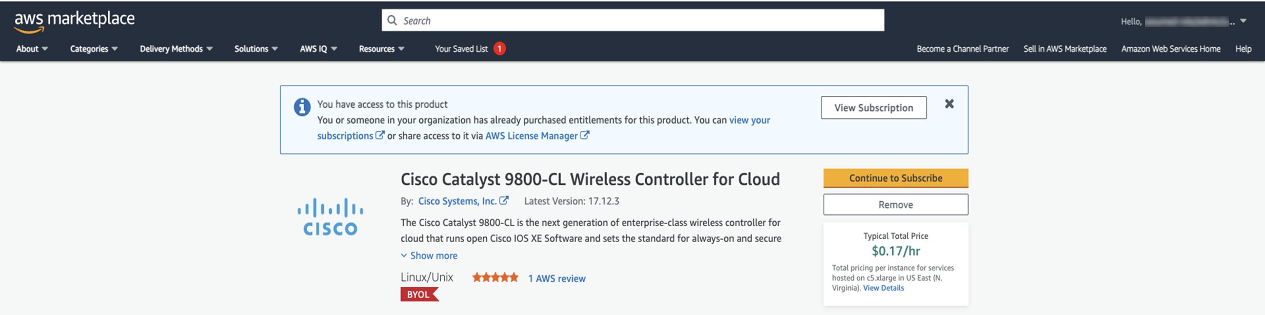 Click Continue to Configuration. 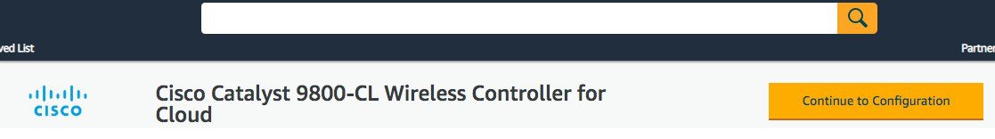 |
||
|
Step 5 |
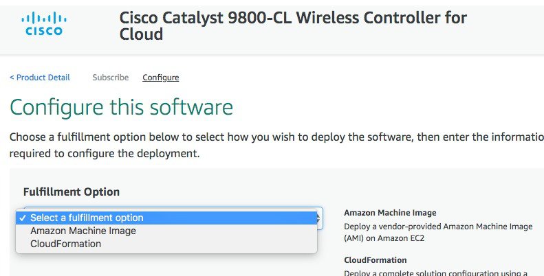
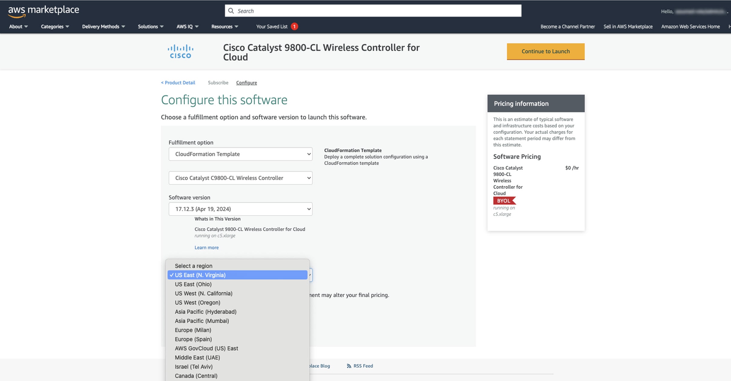
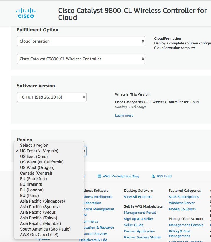
From the Fulfillment Option drop-down list, choose CloudFormation.
Scroll down and choose the region where you want to create the C9800-CL instance.
Click Continue to Launch. |
||
|
Step 6 |
Click Launch. 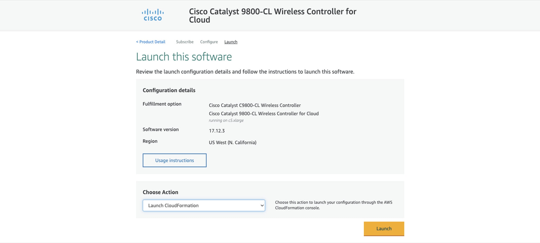 |
||
|
Step 7 |
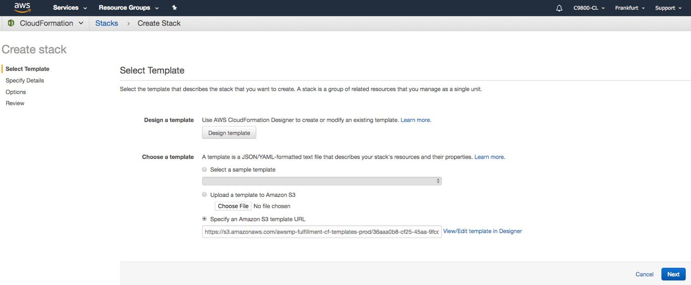
You are redirected automatically to the CloudFormation service in the AWS console, and the template is selected.
Click Next.
|
||
|
Step 8 |
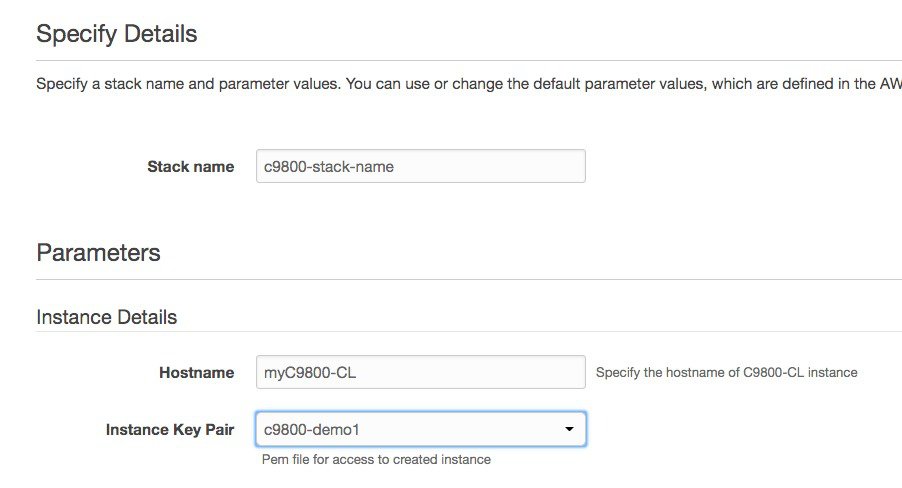
Enter the stack and instance details. The stack name is any name of your choice. Enter the C9800 hostname and choose the previously created key pair.
|
||
|
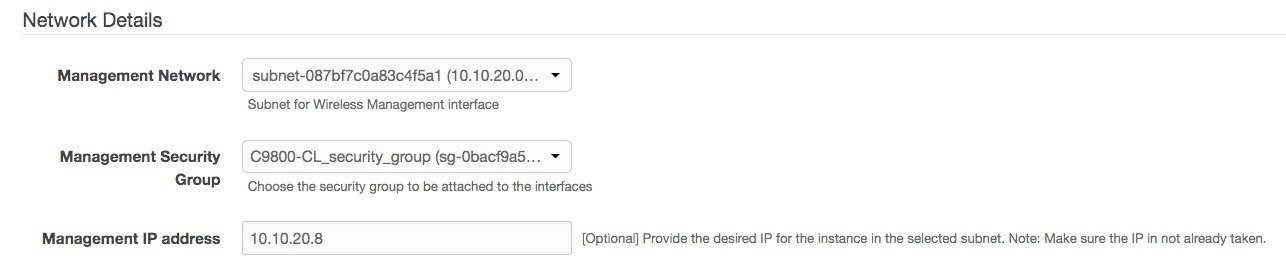
Step 9 |
Enter the network details. Choose the subnet and security group to assign to the wireless management interface. Make sure that the subnet and security group that you choose belong to the same selected VPC. Optionally, you can enter the IP address that will be assigned to the C9800 instance within the selected subnet. Make sure that the specific IP belongs to the subnet you selected and is not already in use. Otherwise, the stack creation will fail.
|
||
|
Step 10 |
Enter the username and password to remotely connect to the instance. This step is optional. If you don’t configure the username and password, you can log in via SSH using the default AWS user (ec2-user) and the instance key pair specified in the preceding step. Choose the instance type according to the scale. Cisco supports c5.xlarge (the default value), which corresponds to the supported scale of 1000 APs and 10,000 clients. 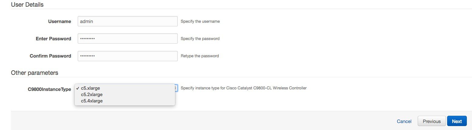 Click Next. |
||
|
Step 11 |
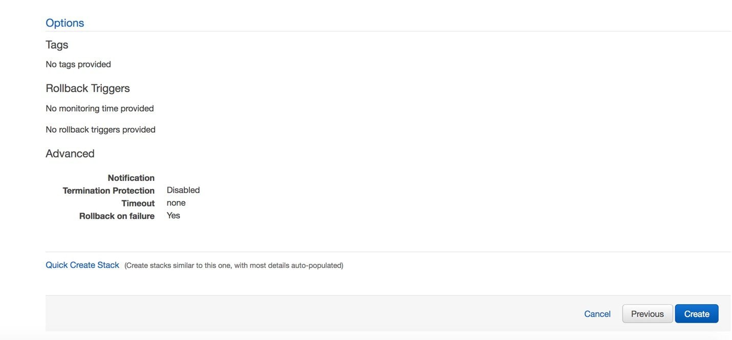
Leave the option page to the default and click Next. |
||
|
Step 12 |
Review the settings and click Create.
|
||
|
Step 13 |
Wait several seconds for the status to change from CREATE_IN_PROGRESS to CREATE_COMPLETE. 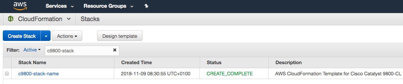 If the stack creation fails, the status shows ROLLBACK COMPLETE. Click the stack name to see the failure reason. In the following example, the IP address that was chosen was already assigned. 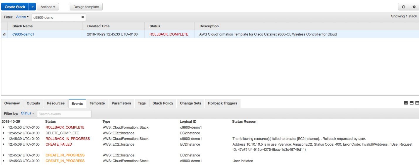 |
||
|
Step 14 |
Go to the EC2 dashboard and click Running Instances.  |
||
|
Step 15 |
The new instance is in Initializing state. Wait for several minutes until it changes to green.  Notice that the instance has the requested private IP and no public IP. At this point, the cloud instance of your Catalyst
9800 Wireless Controller is ready to use through a VPN connection.
 |


Launching a C9800-CL from AWS Marketplace with AMI
This method allows you to instantiate a C9800-CL controller from AWS Marketplace using a guided web interface. Compared to the CloudFormation template this requires more user inputs but also gives you more control in terms of the different cloud settings.
Prerequisites
-
A Managed VPN connection is created from the corporate network to the VPC
-
A VPC is created with the desired subnet for the C9800 Wireless Management interface
-
The C9800 CloudFormation template. The customer will not need to deal with the CloudFormation template as this is automatically integrated in the launching procedure; if desired, the customer can download and view the CloudFormation template file from the AWS Market Place page of the product.
-
Amazon Machine Instance ID (AMI-ID) for the desired 9800 software release; the AMI will be available in AWS market place.
-
If you don’t have one already, create a key pair by going to EC2 dashboard > Network & Security > Key pairs and click on “Create Key Pair”
Steps to Launch a C9800-CL from AWS Marketplace with AMI
Procedure
|
Step 1 |
Sign in AWS Marketplace: https://aws.amazon.com/marketplace/
|
||
|
Step 2 |
Search for Catalyst 9800 or C9800-CL and from the search results, click on the Cisco Catalyst 9800-CL Wireless Controller for Cloud page.  |
||
|
Step 3 |
The product overview page appears:  Here you can read all the information about the product, support, licensing and estimate the cost of deploying the C9800-CL in the different AWS regions. |
||
|
Step 4 |
Click on “Continue to subscribe” in the top right corner.  And then “continue to configuration”.  |
||
|
Step 5 |
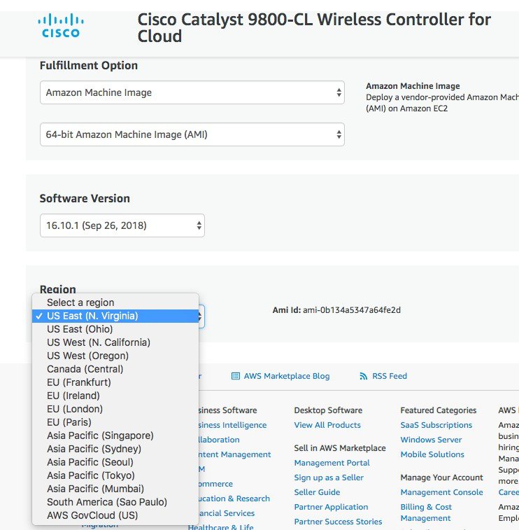
In the following page click on the fulfilment option and select Amazon Machine Image.  On the page that appears, scroll down and select the Region where you want to create the C9800-CL instance.
Click “Continue to Launch” |
||
|
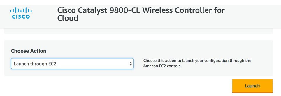
Step 6 |
On the following launch software page select Choose Action and set it to “Launch from Website”. The alternative is “Launch through EC2” which is described in the next section as you will be redirected to the AWS console 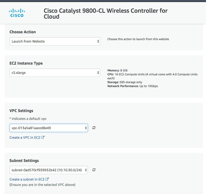 In this page enter the required information: EC2 instance type should be left at default. Choose the VPC, subnet. Scroll down to find the Security group settings and to enter the key-pair. 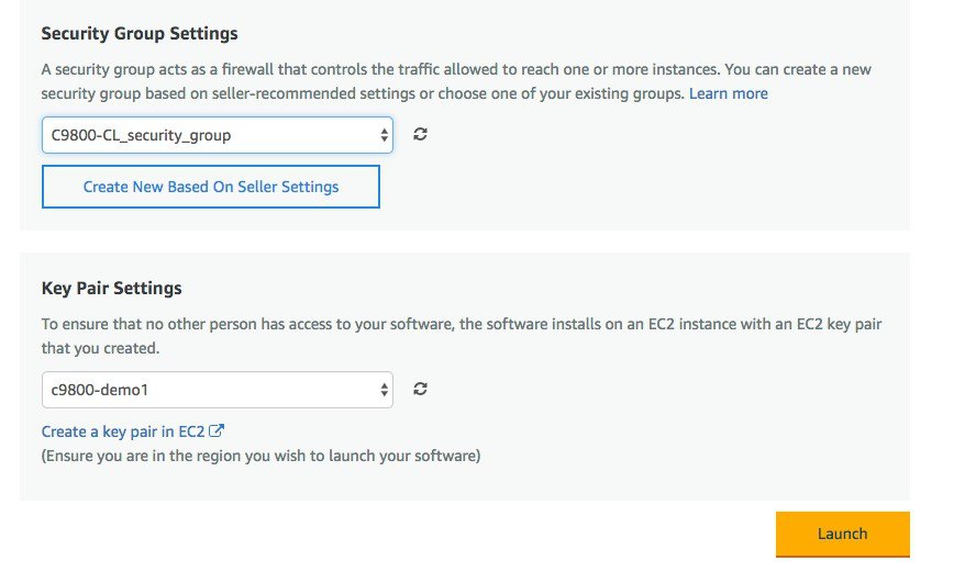 When done click Launch. |
||
|
Step 7 |
You will get a message that the instance has been successfully launched. 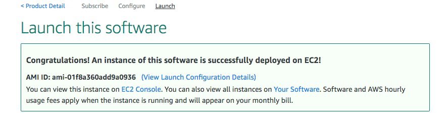 |
||
|
Step 8 |
Go to EC2 dashboard and click on Running Instances: 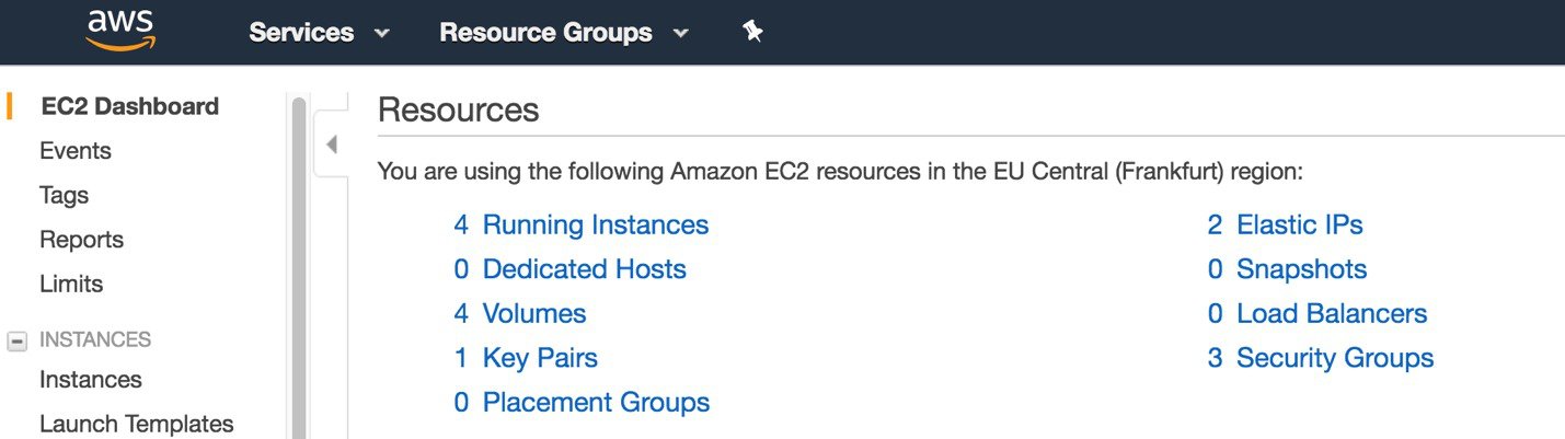 |
||
|
Step 9 |
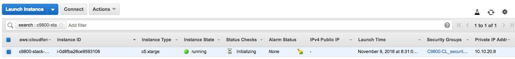
The new instance will be in Status Checks (System Status Checks & Instance Status Checks) initializing. Wait for few minutes until it goes in goes green.
Notice that the instance has no public IP because that’s the mode supported for the initial release. At this point the cloud instance of your Catalyst 9800 Wireless Controller is ready to use and you can be reached through the VPN connection.
|

Launching a C9800-CL instance directly from AWS console
This section describes how to launch an instance directly from the AWS console.
Prerequisites
-
A Managed VPN connection is created from the corporate network to the VPC
-
A VPC is created with the desired subnet for the C9800 Wireless Management interface
-
The C9800 CloudFormation template. The customer will not need to deal with the CloudFormation template as this is automatically integrated in the launching procedure; if desired, the customer can download and view the CloudFormation template file from the AWS Market Place page of the product.
-
Amazon Machine Instance ID (AMI-ID) for the desired 9800 software release; the AMI will be available in AWS market place.
-
If you don’t have one already, create a key pair by going to EC2 dashboard > Network & Security > Key pairs and click on “Create Key Pair”
Steps to launch C9800-CL instance directly from AWS console
This section describes the step by step procedure to launch a WLC instance directly from the Amazon Machine Image (AMI). After FCS, the user can select the AMI directly in AWS Market Place, by search for C9800-CL and select the image.
Before you begin
Procedure
|
Step 1 |
Sign in AWS Marketplace: https://aws.amazon.com/marketplace/
|
||||
|
Step 2 |
Search for Catalyst 9800 or C9800-CL and from the search results, click on the Cisco Catalyst 9800-CL Wireless Controller for Cloud page.
|
||||
|
Step 3 |
The product overview page will appear:
Here you can read all the information about the product, support, licensing and estimate the cost of deploying the C9800-CL in the different AWS regions. |
||||
|
Step 4 |
Click on “Continue to subscribe” in the top right corner 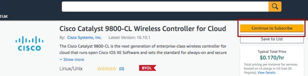 And then “continue to configuration” |
||||
|
Step 5 |
In the following page click on the fulfilment option and select CloudFormation
Scroll down and select the Region where you want to create the C9800-CL instance.
Click “Continue to "Launch” |
||||
|
Step 6 |
On the following launch software page select Choose Action and set it to “Launch through EC2” and you will be redirected to the AWS console.
|
||||
|
Step 7 |
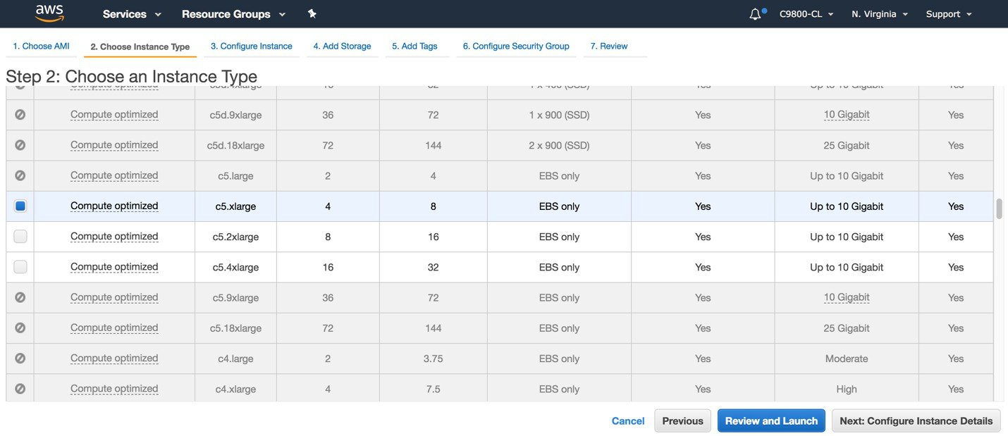
In the firstEC2 screen on AWS console, select the instance type: In the first release the only supported type is c5.xlarge, c5.2xlarge and c54xlarge. The recommended type is c5.xlarge because it supports 1k AP-10k clients with the required compute resources. Click on Next: Configure Instance details:
|
||||
|
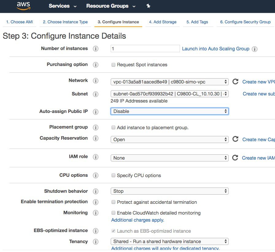
Step 8 |
Configure the instance details: select the VPC, select the subnet in the VPC.
By default, the auto-assign Public IP field shows “Use subnet setting”. But since at FCS we don’t support the Public IP, it’s recommended to set this to disable. 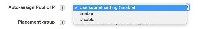 If the customer wants to the instance to get assigned a public IP for remote management, this setting can be changed. It will be up to the customer to then configure a default route and connect the VPC with the internet gateway. Cisco doesn’t support APs joining the C9800-CL using the public IP address, so it’s also customer responsibility to configure the VPC with the security group to filter CAPWAP traffic. Finally select the “shutdown behavior”, it can be either “stop” or “terminate” the instance, by default is “stop”. |
||||
|
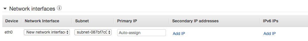
Step 9 |
Set the network interface details: you can configure a static IP here. Make sure the address is part of the same subnet you have selected previously and that the address is free, otherwise you will get an error.
|
||||
|
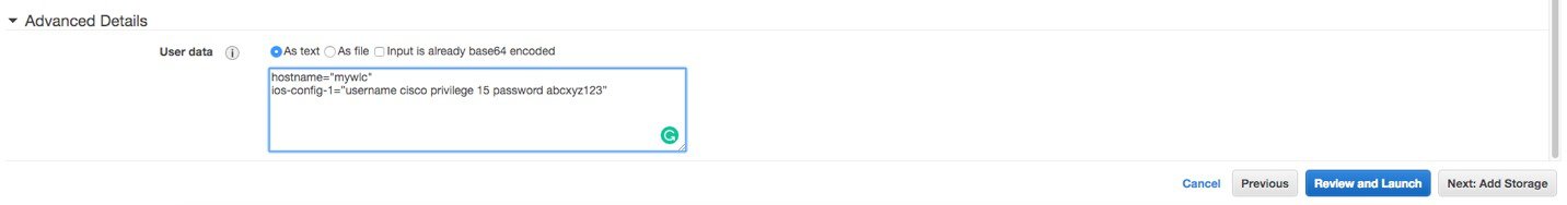
Step 10 |
Add user data in the advanced details section. Here you can enter any IOS commands you want to boot the instance with. For example, here we give a hostname and username and pwd to later access the box via ssh. Click Next.
Examples:
|
||||
|
Step 11 |
Choose the type of storage you want. Recommendation is to use SSD 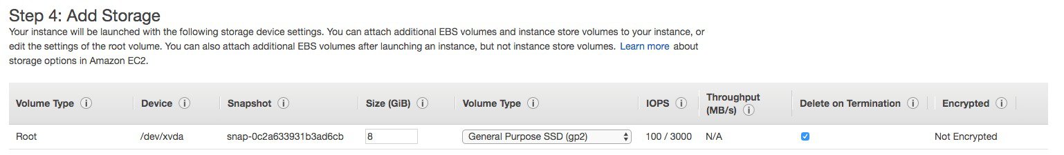 |
||||
|
Step 12 |
Select the Security group or create a new one and click “Review and Launch”. 
 |
||||
|
Step 13 |
Review and click Launch. You will be asked to select a key pair or create a new one and check that you acknowledge that you have access to the key pair. Then click Launch instance.  After few minutes, your cloud instance of your Catalyst 9800 Wireless Controller is ready to use |
Connecting to C9800-CL in AWS
At this point your C9800 Wireless Controller in the cloud is ready to use. You can https://<IP of Wireless Management interface> for starting the DAY 0 GUI or ssh to the box. The IP is the private IP that was either automatically assigned by AWS or you have reserved with the CloudFormation template or on the AWS console.
To ssh you have two options:
-
a. Use the username/pwd provided during the instance creation
-
Use the .pem file to authenticate using the certificate
-
chmod 400 <file>.pem
-
issh -i “file name.pem” ec2-user@<c9800-CL IP>
-
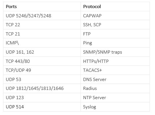
Note |
If you want the instance to be reachable via the public IP, make sure you have a default route in the VPC Route table as explained in the “Establishing a VPN connection using the AWS VPN router” section above. Make sure that the security group would only allow the desired protocol on the Public IP. |
DAY 0 configuration for C9800-CL on Public Cloud
The purpose of the DAY 0 Web Graphical User Interface (GUI) is to facilitate the first Catalyst 9800 Wireless Controller setup and provide the instance with the necessary configurations for APs and clients to join. The DAY 0 GUI is triggered every time the wireless controller has not been configured with a Regulatory Country Domain and hence is not operational.
To connect to the DAY 0 GUI, just login to the defined Device Management/Wireless Management interface using https.
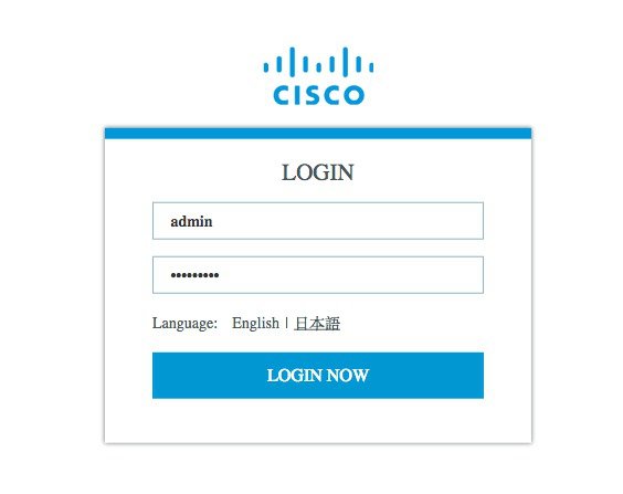
To login use the username and password credentials given during the C9800 instance creation described in the previous sections.
Once logged in, the user is presented with a simplified configuration flow to set the basic parameters and have the controller fully operational.
In the first page, enter the required information:
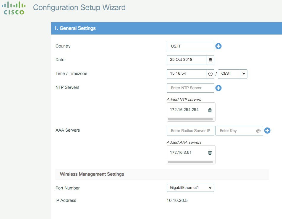
These are: Country code, Date and Time, NTP (optional) and AAA Server (optional). Notice that only interface Gigabit 1 is present on the box as only one interface is supported. Click Next
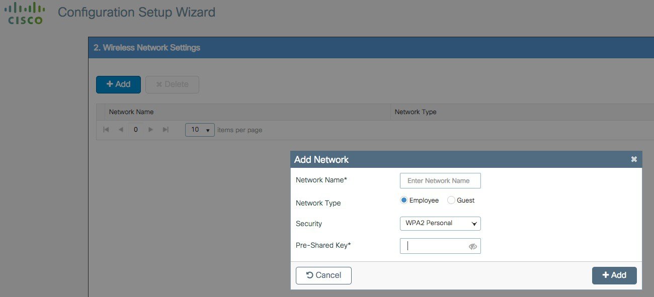
In the next page you can add a WLAN (optional) so that clients can connect. In this example the PSK dialogue is shown:
In the next page the user can set some basic RF parameters and the AP certificate.
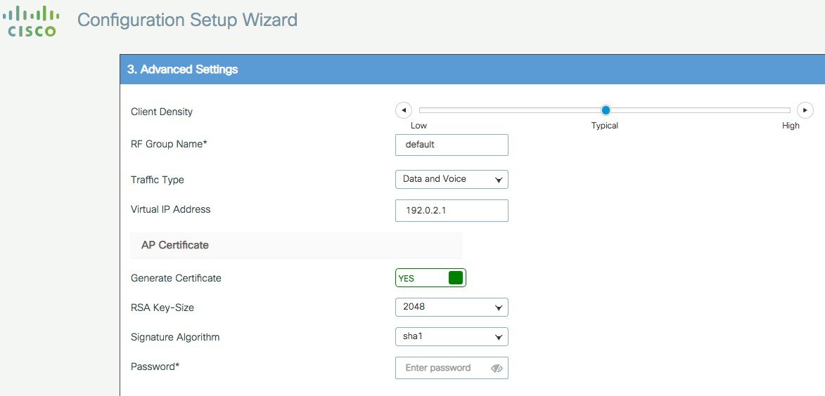
A trustpoint is basically a certificate authority who you trust, and it is called a trustpoint because you implicitly trust this authority. A trustpoint certificate is a self-signed certificate, hence the name trustpoint, since it does not rely on the trust of anyone else or other party. A trustpoint is needed for AP to join the C9800-CL and the user can decide to auto generate one during DAY 0, or can toggle the “Generate Certificate” to NO and then it will have to configure its own certificate authority at DAY 1 for APs to join.
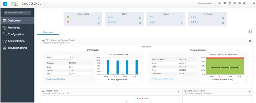
Click Summary to review the configuration and then click Finish. The configuration and trustpoint will be pushed to the device and the user will be logged out. The 9800-CL controller will not reboot but it will take about 60s to prompt the user to login again; enter the same credentials:

This time it will skip the DAY 0 page since the box has already an initial configuration, and the user will be redirected to the main Dashboard:
C9800-CL Configuration via CLI: Skip the Day-0 Guided Flow
If you want to skip the day-0 web-based guided flow and use the CLI to configure the basic settings, complete the following steps. After completing these steps, you can access the GUI for the day-1 configuration.
For C9800-CL on AWS cloud, GigabitEthernet 1 is the only available interface and has the following characteristics:
-
It is a Layer 3 interface (AWS only supports this type of interface)
-
It gets a static IP address
There is no wireless CLI wizard for C9800-CL. The following steps are manual.
Procedure
|
Step 1 |
Access the CLI via SSH. Use the .pem file to authenticate with the certificate.
|
||
|
Step 2 |
Optionally, set the hostname: |
||
|
Step 3 |
Enter the config mode and add login credentials: |
||
|
Step 4 |
Verify the GigabitEthernet 1 configuration and IP address. The interface is configured with a static IP address. |
||
|
Step 5 |
Disable the wireless network to configure the country code. |
||
|
Step 6 |
Configure the AP country domain. This configuration triggers the GUI to skip the day-0 flow, because the C9800 requires a country code to be operational. |
||
|
Step 7 |
A certificate is required for the AP to join the virtual C9800. This can be created automatically via the day-0 flow or manually by entering the following commands.
To access the main dashboard, go to https://<IP of the wireless management interface>. Use the credentials you entered earlier. Because the device has a country code configured, the GUI skips the day-0 page. You will get access to the main dashboard for day-1 configuration. |
Resetting C9800-CL to factory default
There is no console access on the C9800-CL in the AWS cloud. The only access to the instance is through the network and hence through the IP and credentials that have been configured at bootstrap. It’s easy to understand that erasing the configuration completely will lock out the user without any way of recovering.
In other words we cannot use the traditional IOS-XE methods of resetting the instance to factory default such as “wr erase” and/or setting the configuration register to ignore the startup-config.
The only way to have an instance with factory default settings is to spawn a new one.
 Feedback