Wireless Plug and Play Deployment Guide
Available Languages
Contents
- Introduction
- Components Used
- Requirement Overview
- APIC VM Install
- DHCP Requirement
- DNS Requirement
- AP PnP Agent Requirement
- Feature Configuration Step-by-Step
- Site Pre-Provisioning Workflow
- Creating a Site or Project
- Adding a Device
- Uploading the Configuration File
- Deploying Devices
- Claiming the Device
- Bulk Import Sites and Devices
- Troubleshooting the Cisco Network Plug and Play
- Checking Cisco Network Plug and Play Status
- Reviewing the Status from the Dashboard
- Public Cloud Re-direction Service
Introduction
The Cisco Network Plug and Play solution provides a simple, secure, unified, and integrated offering for enterprise network customers to ease new branch or campus rollouts, or for provisioning updates to an existing network. The solution allows use of Cloud Redirection service, on-prem, or combination which provide a unified approach to provision enterprise networks comprised of Cisco routers, switches, and wireless devices with a near zero touch deployment experience.
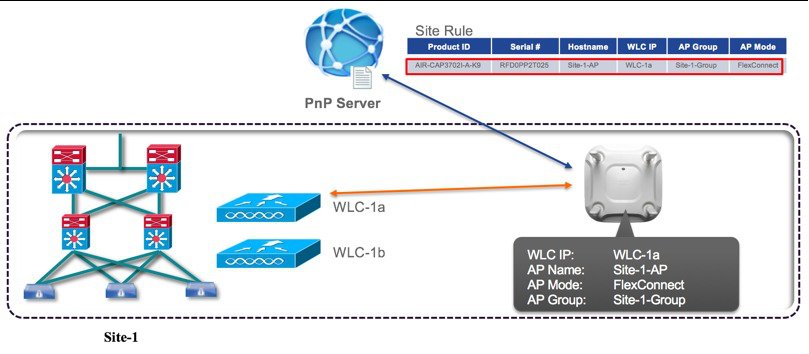
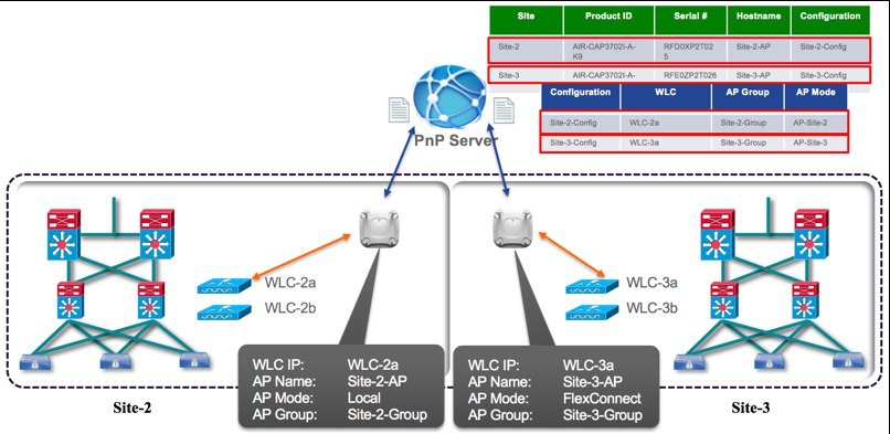
This deployment guide introduces the Cisco Network Plug and Play application for wireless access points. This application allows you to pre-provision the remote site. When you provision a large site, you can use the Cisco Network Plug and Play application to pre-provision the site and add access points to the site. This includes entering access point information and setting up a bootstrap configuration if required. The bootstrap configuration enables the Plug and Play Agent to configure the access point such as the WLC info, hostname, AP group, FlexGroup, AP mode and so on.
When you create small sites where pre-provisioning is not required, access points can be deployed without prior set up on the Cisco Network Plug and Play application and then claimed. When an installer installs and powers up the access point, it auto-discovers the Cisco APIC-EM controller by using the DHCP, DNS or cloud redirection service. After the auto-discovery process is complete, the AP either joins a WLC with configuration from local PnP server, or communicates with the cloud redirection service for direction to target WLC or PnP server.
Components Used
APIC-EM minimum release of 1.0.1.30 with Cisco Network Plug and Play, virtually hosted in a Cisco UCS or equivalent server.
VMWare ESXi 5.x/6.x Virtual Machine minimum requirement:
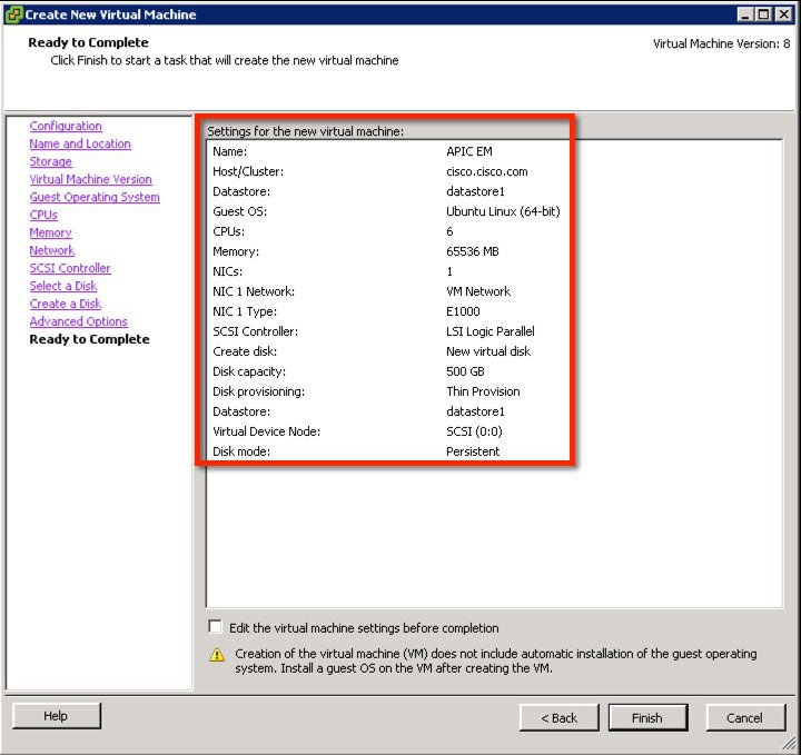
Virtual Machine Options VMware ESXi Version 5.1/5.5 Server Image Format ISO Hardware Specifications Virtual CPU (vCPU) 6 CPU (speed) 2.4 GHz Memory 64 GB
Note For a multi-host deployment (2 or 3 hosts) only 32 GB of RAM is required for each host
Disk Capacity 500 GB Disk I/O Speed 200 Mbps Network Adapter
Note A single network adapter or network interface controller (NIC) is the minimum requirement. For security, we recommend that you use and configure two NICs on the server. See Security in the Limitations and Restrictions section of these release notes for additional information.
Networking Web Access Required Browser The following browsers are supported when viewing and working with the Cisco APIC-EM: Cisco Series Wireless LAN Controller with software release 8.3.90.25 and above
802.11n Access Points with PnP agent in software release 8.3
Cisco Catalyst Switch
Client computer (e.g. laptop) that is Windows or Mac, with an available wired Ethernet port.
Requirement Overview
Follow these recommendations when deploying the Cisco Network Plug and Play solution:
Install APIC EM Controller VM (optional if testing on-prem PnP server).
Configure a DHCP server with option 43 to allow Cisco network devices to auto-discover the APIC-EM controller (option 43 is not required if only testing cloud redirection).
Cloud redirection service requires a connection to the internet, and valid DNS server that can resolve ‘devicehelper.cisco.com’
On-prem PnP server can be added to DNS using ‘pnpserver.yourlocal.domain’
Pre–provision the device configuration in the Cisco Network Plug and Play application for all new devices to be deployed. This includes setting up the site and devices in it with the access point info of serial numbers and bootstrap configuration.
Device bring up order—In general, routing and upstream devices should be brought up first. Once the router and all upstream devices are up and provisioned, switches and downstream devices can be brought up. The Cisco Network Plug and Play Agent attempts to auto-discover the APIC-EM controller only during initial device startup. If at this time, the device cannot contact the controller, device provisioning fails, so upstream devices should be provisioned first
Cisco Router Trunk/Access Port Configuration–Typical branch networks include routers and switches. One or more switches are connected to the WAN router and other endpoints like IP phones and access points connect to the switches. When a switch connects to an upstream router, the following deployment models are supported for Cisco Network Plug and Play
Downstream switch is connected to the router using a switched port on the router. In this type of connection, the switched port on the router must be configured as an access port. The Cisco Network Plug and Play solution does not work for the switch if the switched port on the router is configured as a trunk port.
APIC VM Install
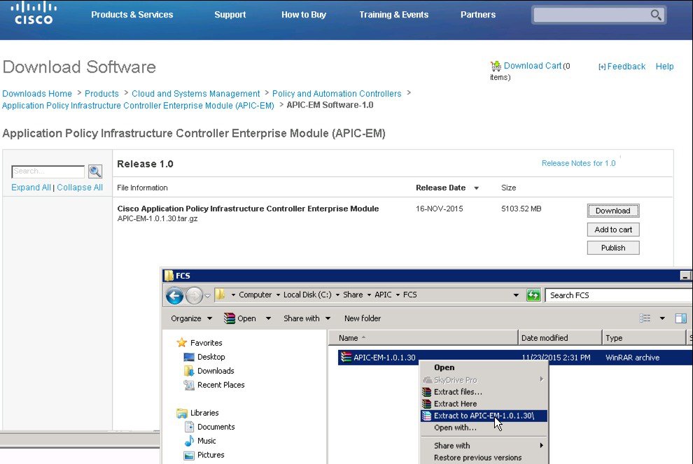
ProcedureDownload the appropriate APIC ISO image provided on the Cisco website:
https://software.cisco.com/download/release.html?mdfid=286208072&flowid=77162&softwareid=286291196&release=1.0&relind=AVAILABLE&rellifecycle=&reltype=latestExtract the tar.gz file to obtain the ISO image of APIC-EM.
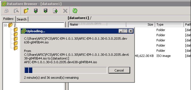
Upload the ISO to the ESXi 5.x server.
Create a new Virtual Machine with the following custom configuration settings:
Note
Check release notes for latest support and requirement of APIC EM.
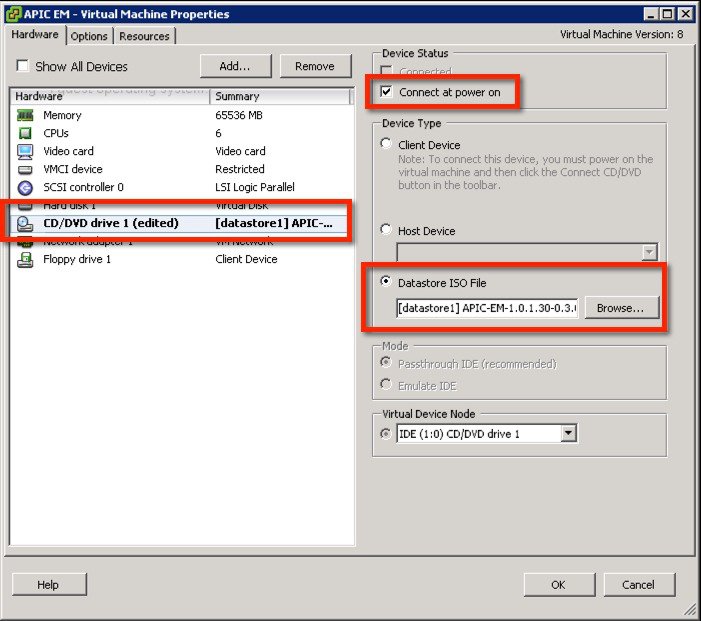
Mount the ISO in the CD/DVD then power up the VM.
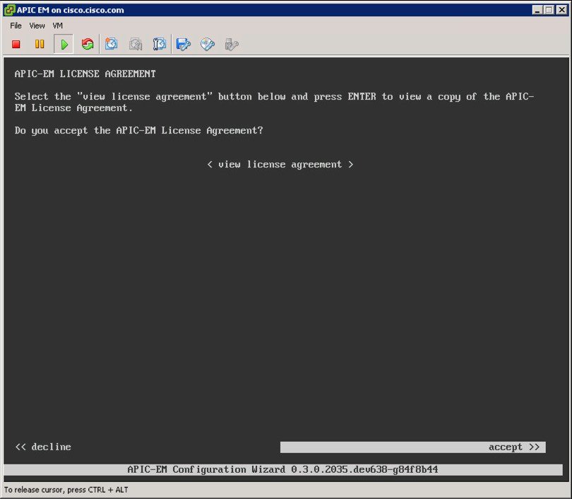
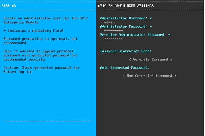
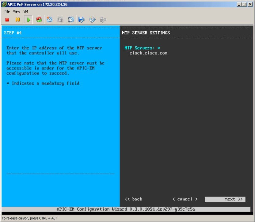
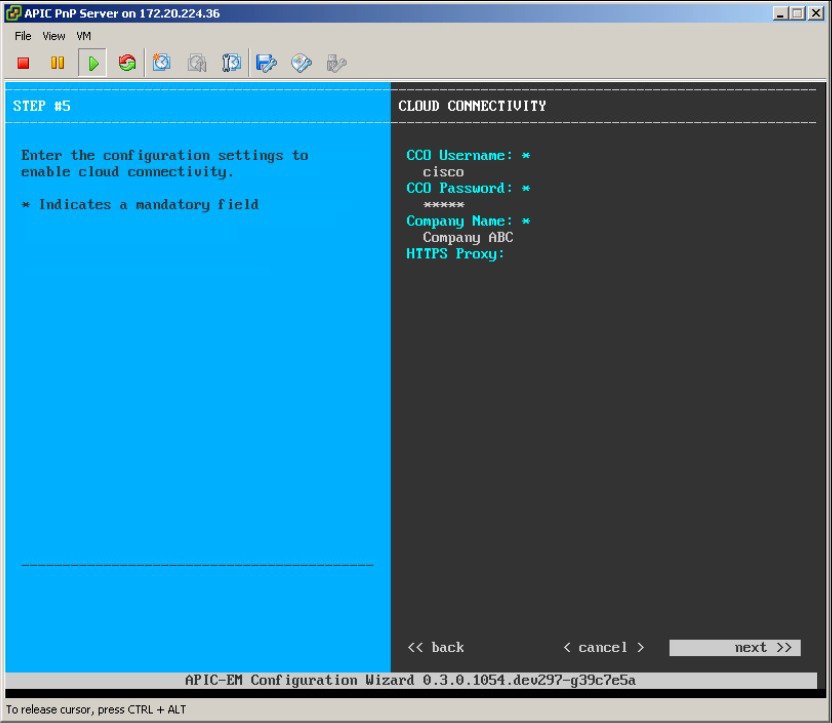
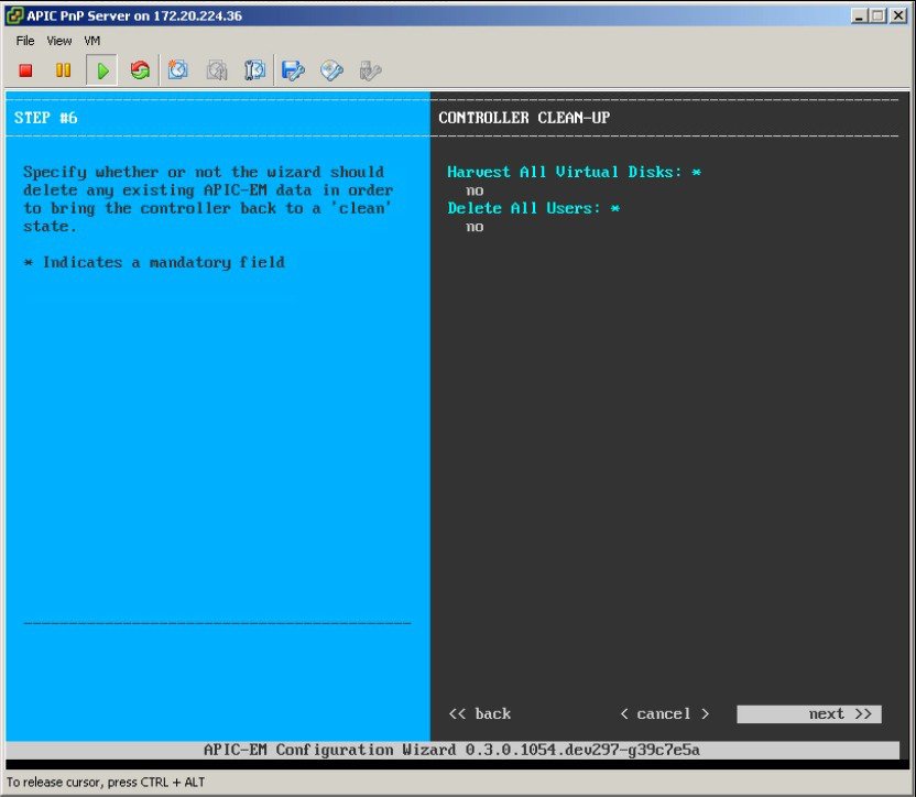
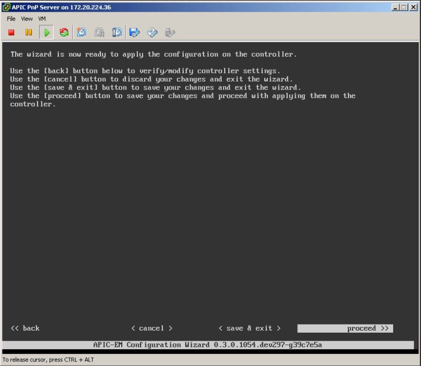
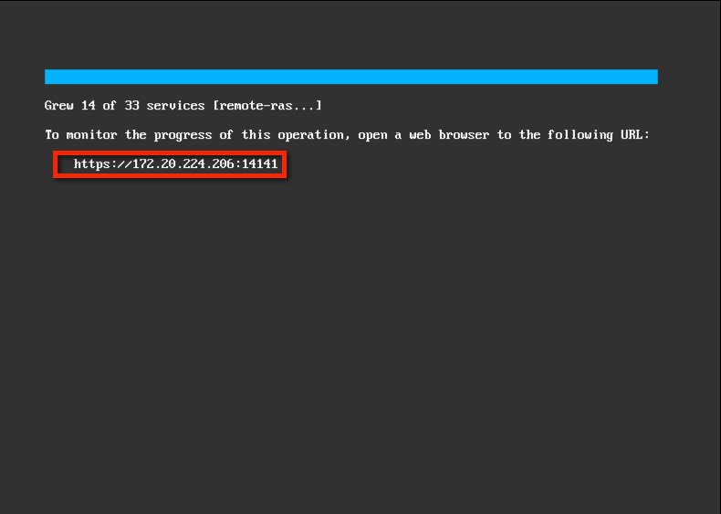
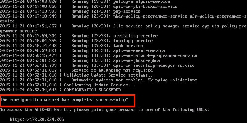
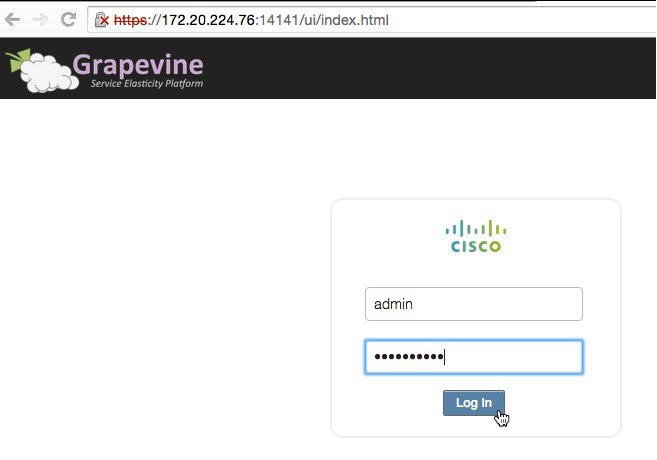
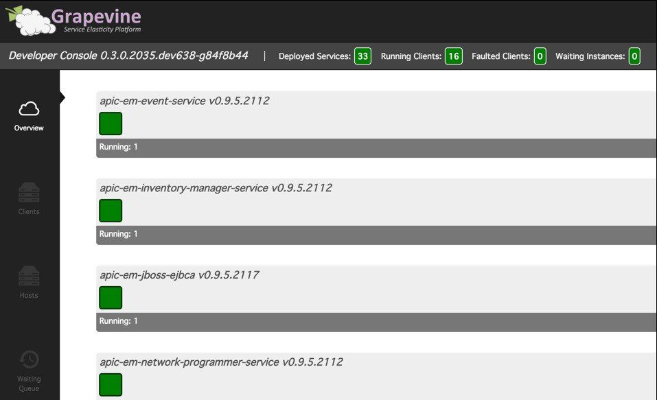
Allow the installation to complete, the VM will reboot as required. Once completed, the APIC-EM License Agreement will prompt to accept and continue (use keyboard to input and navigate).
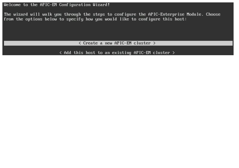
Select 'Create a new APIC-EM cluster'.
DHCP Requirement
The prerequisites for the DHCP auto-discovery method are as follows:
New devices can reach the DHCP server
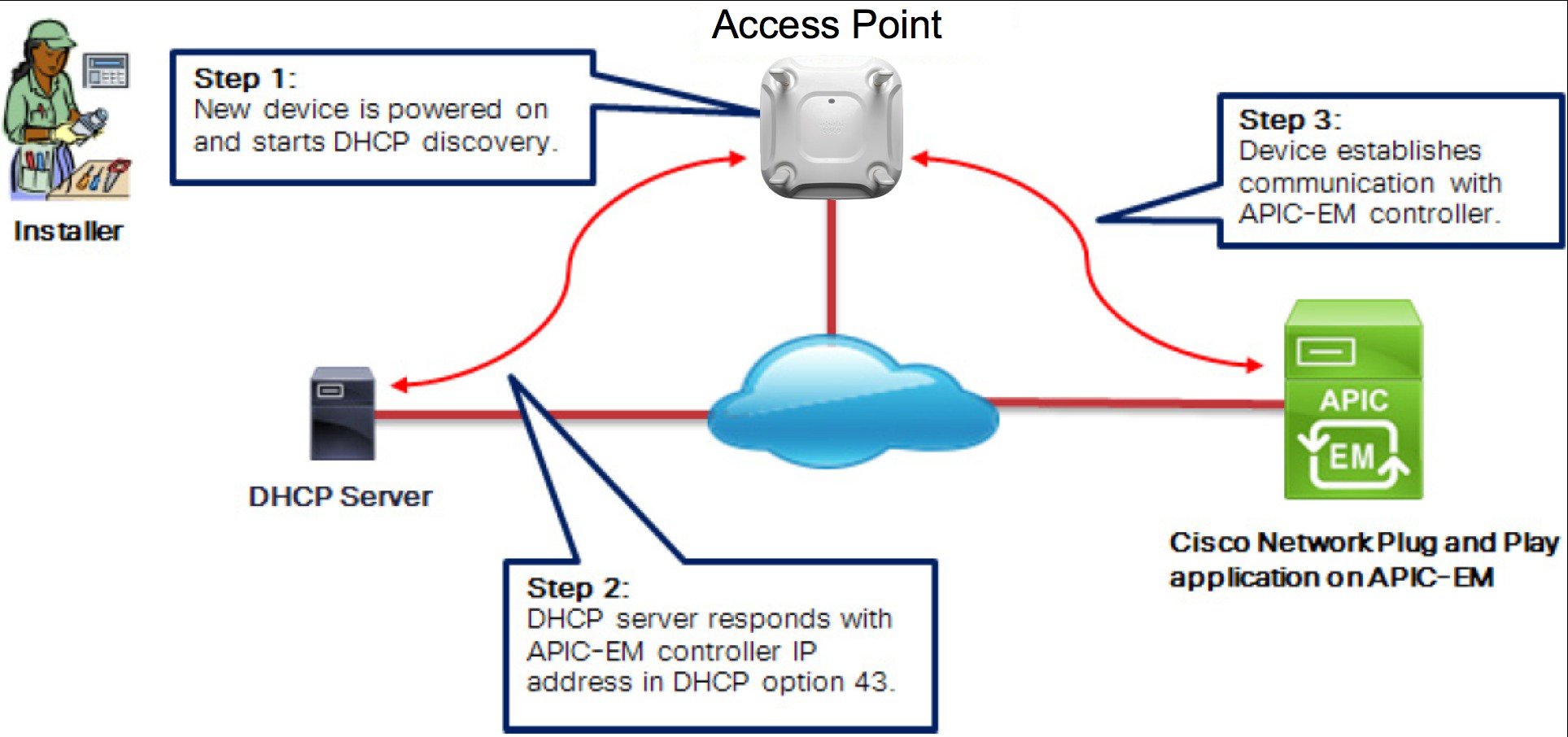
The DHCP server is configured with option 43 for Cisco Network Plug and Play
DHCP option 43 consists of a string value that is configured as follows on a Cisco router CLI that is acting as a DHCP server:
Name of DHCP pool ip dhcp pool pnp_device_pool Range of IP addresses assigned to clients network 192.168.1.0 255.255.255.0 Gateway address default-router 192.168.1.1 option 43 ascii "5A1N;B2;K4;I192.168.1.123;J80" ** ** Option 43 string, copy/paste include quotes, insert your APIC management IP address here.
DNS Requirement
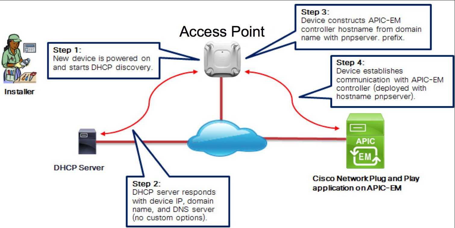
If DHCP discovery fails to get the IP address of the APIC-EM controller, for example, because option 43 is not configured, the Cisco Plug and Play IOS Agent falls back on a DNS lookup method. Based on the network domain name returned by the DHCP server, it constructs a fully qualified domain name (FQDN) for the APIC-EM controller, using the preset hostname pnpserver.
For example, if the DHCP server returns the domain name " customer.com ", the Cisco Plug and Play IOS Agent constructs the FQDN "pnpserver.customer.com ". It then uses the local name server to resolve the IP address for this FQDN.
The prerequisites for the DNS auto-discovery method are as follows:
New devices can reach the DHCP server
For on-premise, the APIC-EM controller is deployed with the hostname “pnpserver”
AP PnP Agent Requirement
Cisco CAPWAP access points with software release 8.3 provides the necessary recovery image to support PnP. An example output from the console of a NEW AP during boot up will show the following:
*Mar  1 00:00:13.027: %LWAPP-3-CLIENTERRORLOG: Load nvram:/lwapp_ap.cfg config failed,trying backup...
*Mar  1 00:00:13.027: %LWAPP-3-CLIENTERRORLOG: Load nvram:/lwapp_ap.cfg.bak config failed...
*Mar  1 00:00:15.035: %LINK-6-UPDOWN: Interface GigabitEthernet0, changed state to up
*Mar  1 00:00:15.107: %SYS-5-RESTART: System restarted --
Cisco IOS Software, C3700 Software (AP3G2-RCVK9W8-M), Experimental Version 15.3(20150923:181842)[pkpanda 173]
Copyright (c) 1986-2015 by Cisco Systems, Inc.
Compiled Wed 23-Sep-15 11:21 by pkpanda
*Mar  1 00:00:15.107: %SNMP-5-COLDSTART: SNMP agent on host APfc5b.395a.b56c is undergoing a cold start
*Mar  1 00:00:15.191: %LWAPP-3-CLIENTERRORLOG: NumOfSlots Mismatch Reinit all Radios config rcb:0 Cfg:2
*Mar  1 00:00:15.359: %SSH-5-ENABLED: SSH 2.0 has been enabledlwapp_crypto_init: MIC Present and
   Parsed Successfully
*Mar 1 00:00:16.151: %LINEPROTO-5-UPDOWN: Line protocol on Interface BVI1, changed state to up *Mar 1 00:00:20.003: DPAA Initialization Complete *Mar 1 00:00:20.003: %SYS-3-HARIKARI: Process DPAA INIT top-level routine exited *Mar 1 00:00:21.003: %LINEPROTO-5-UPDOWN: Line protocol on Interface GigabitEthernet0, changed state to up *Mar 1 00:00:23.003: %LINK-6-UPDOWN: Interface BVI1, changed state to down *Mar 1 00:00:24.003: %LINEPROTO-5-UPDOWN: Line protocol on Interface BVI1, changed state to down *Mar 1 00:00:27.151: %LINK-6-UPDOWN: Interface BVI1, changed state to up *Mar 1 00:00:28.151: %LINEPROTO-5-UPDOWN: Line protocol on Interface BVI1, changed state to up *Mar 1 00:00:28.223: %PNPA-DHCP Op-43 Msg: Process state = READY *Mar 1 00:00:28.223: %PNPA-DHCP Op-43 Msg: OK to process message *Mar 1 00:00:28.223: XML-UPDOWN: PNPA_DHCP_OP43 XML Interface(102) UP. PID=47 *Mar 1 00:00:28.223: %PNPA-DHCP Op-43 Msg: _pdoon.1.ntf.don=47 *Mar 1 00:00:28.223: %DHCP-6-ADDRESS_ASSIGN: Interface BVI1 assigned DHCP address 10.10.50.248, mask 255.255.255.0, hostname APfc5b.395a.b56c*Mar 1 00:00:28.223: %PNPA-DHCP Op-43 Msg: _pdoop.1.org=[A1D;B2;K4;I192.168.1.123;J80;] *Mar 1 00:00:28.223: %PNPA-DHCP Op-43 Msg: _pdgfa.1.inp=[B2;K4;I192.168.1.123;J80;] *Mar 1 00:00:28.223: %PNPA-DHCP Op-43 Msg: _pdgfa.1.B2.s12=[ ipv4 ] *Mar 1 00:00:28.223: %PNPA-DHCP Op-43 Msg: _pdgfa.1.K4.htp=[ transport http ] *Mar 1 00:00:28.223: %PNPA-DHCP Op-43 Msg: _pdgfa.1.Ix.srv.ip.rm=[ 192.168.1.123 ] *Mar 1 00:00:28.223: %PNPA-DHCP Op-43 Msg: _pdgfa.1.Jx.srv.rt.rm=[ port 80 ] *Mar 1 00:00:28.223: %PNPA-DHCP Op-43 Msg: _pdoop.1.ztp=[pnp-zero-touch] host=[] ipad=[192.168.1.123]port=80 *Mar 1 00:00:28.223: %PNPA-DHCP Op-43 Msg: _pors.done=1 *Mar 1 00:00:28.223: %PNPA-DHCP Op-43 Msg: _pdokp.1.kil=[PNPA_DHCP_OP43] pid=47 idn=[BVI1] *Mar 1 00:00:28.223: XML-UPDOWN: BVI1 XML Interface(102) SHUTDOWN(101). PID=47 *Mar 1 00:00:29.155: %PNPA-DHCP Op-43 Msg: _pdoon.2.ina=[BVI1] *Mar 1 00:00:29.155: %PNPA-DHCP Op-43 Msg: _papdo.2.cot=[5A1D;B2;K4;I192.168.1.123;J80;] lot= [5A1D;B2;K4;I192.168.1.123;J80;] *Mar 1 00:00:29.155: %PNPA-DHCP Op-43 Msg: Process state = READY *Mar 1 00:00:29.155: %PNPA-DHCP Op-43 Msg: OK to process message *Mar 1 00:00:29.155: XML-UPDOWN: PNPA_DHCP_OP43 XML Interface(102) UP. PID=34 *Mar 1 00:00:29.155: %PNPA-DHCP Op-43 Msg: _pdoon.2.ntf.don=34*Mar 1 00:00:34.039: No Config Present. PNP required. This indicates PNP process will initiate since no configuration is present.
Example that AP config is present (PNP will not start):
*Mar 1 00:00:34.043: Config Present. PNP Not required.
To check if AP has configuration perform the following command on the AP console:
AP#show capwap client rcb
AdminState		:  ADMIN_ENABLED
SwVer                     	:  8.2.4.4
NumFilledSlots      	:  2
Name                      	:  APfc5b.395a.b56c
Location                  	:  default location
MwarName            	:   					 There is no WLC name
MwarMacAddr      	:  ff01.0000.0000
MwarHwVer           	:  0.0.0.0 There is no WLC IP Address
ApMode                   	:  Local
ApSubMode           	:  Not Configured
OperationState      	:  DISCOVERY
Feature Configuration Step-by-Step
Site Pre-Provisioning Workflow
ProcedureCisco Network Plug and Play allows you to pre-provision and plan for new sites. When you create a new site, Cisco Network Plug and Play enables you to pre-provision the access point(s) configuration file, product serial # and product ID for the selected platform. This simplifies and accelerates the time that it takes to get a site fully functional.
To pre-provision a site on your network, perform these steps:
Adding a Device
Procedure
Uploading the Configuration File
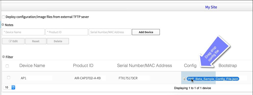
ProcedureThis option allows you to upload the configuration file from your local machine and supports only text format in *.json extension.
To upload the configuration file, perform these steps:
Step 1 Choose Network Plug and Play > Configuration. Step 2 Click Upload and browse to the location where you saved the configuration file. Select the configuration file, and click Open to upload the file.
Step 3 To view the content of the uploaded configuration file, click on the name of the configuration file. This displays the content of the selected file. Step 4 You cannot delete the configuration file that is being used in any device. To delete the configuration file from the list, select the configuration file and click Delete.
- To apply the existing configuration to the device, select the configuration file from the list. Configuration files can be uploaded to ‘Configurations’ in advanced.
- To apply a new configuration to the device, you should upload the configuration file to the server, and then select the configuration file from the list. Or, as shown earlier, you can click-drag a new file to the Config field.
Deploying Devices
After creating the site, you can initiate the provisioning process in the remote site. You should install the device and connect the power cables (or use PoE). Turn on the device, and use the Cisco Plug and Play agent to deploy devices and deliver the bootstrap configuration to the device.
Note
When DHCP or DNS is configured in the network for automatically discovering the Cisco APIC-EM, devices can automatically discover the Cisco APIC-EM and download full configurations, when the power is turned on.
Claiming the Device
ProcedureThe device is added to the unclaimed device list when the device uses the call-home agent capability to connect to the server, before it is provisioned by Cisco APIC-EM, or when the Cisco APIC-EM is not able to match the device against the existing configuration.
To claim the device, perform these steps:
Step 1 Choose Network Plug and Play > Unplanned Devices. Step 2 Select the device from the list and associate the configuration files. Step 3 You can either reuse the existing configuration from the list, or apply the new configuration to the device.
Unsupported for AP:
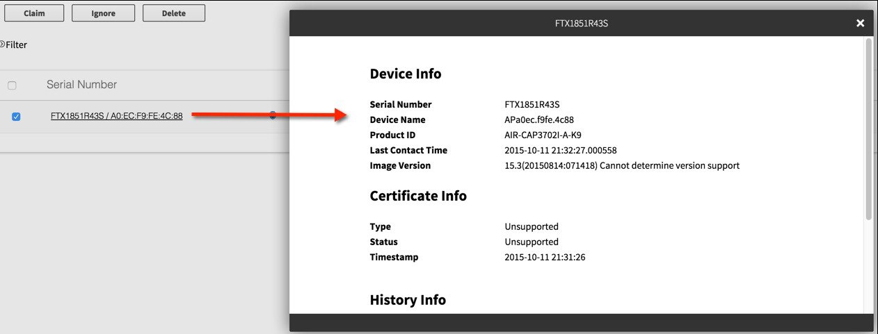
Step 4 Click Claim to claim the device. Step 5 Click on the device link to view the device information.
Bulk Import Sites and Devices
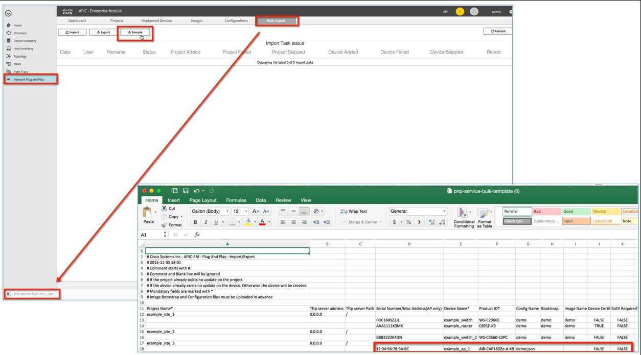
ProcedureYou can use the bulk import feature to import a CSV file that contains the sites and devices attributes.
To perform a bulk import of sites and provisioned devices, perform these steps:
Step 1 Choose Network Plug and Play > Bulk Import. Step 2 Click sample to download the sample file, and add the sites and provisioned devices information:
Site Name
Serial # <or> Mac Address
Device Name (AP-NAME)
Product ID (e.g. AIR-CAP3702I-A-K9)
Config Name (text file already uploaded to server)
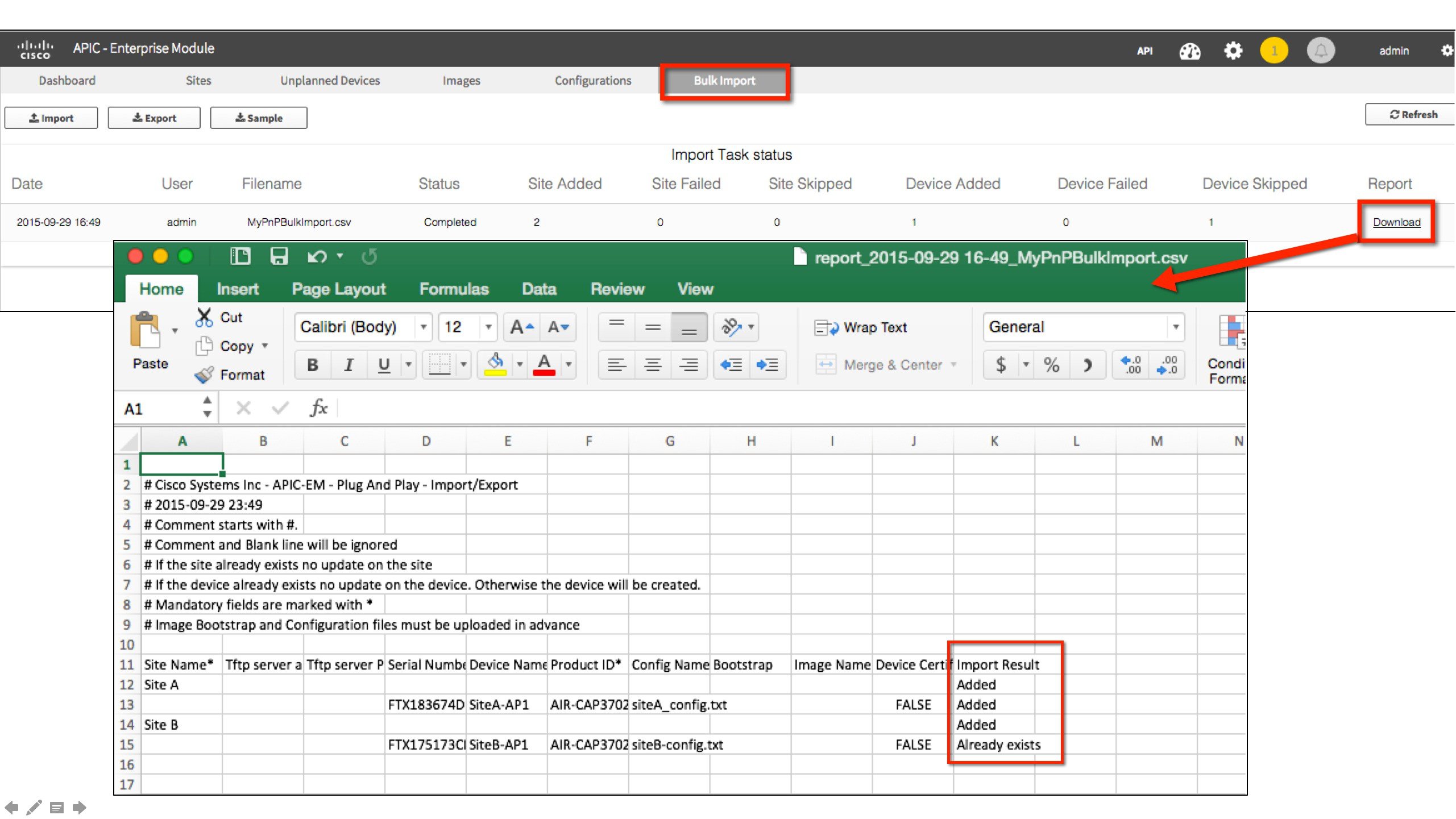
Step 3 Click Import and browse to navigate to the appropriate file. Step 4 Select the file and click Open to import the CSV file.
Step 5 To export the devices information, click Export. The devices information is exported in a CVS format. Use this information to analyze the devices status.
Checking Cisco Network Plug and Play Status
Reviewing the Status from the Dashboard
Procedure
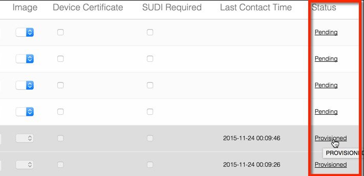
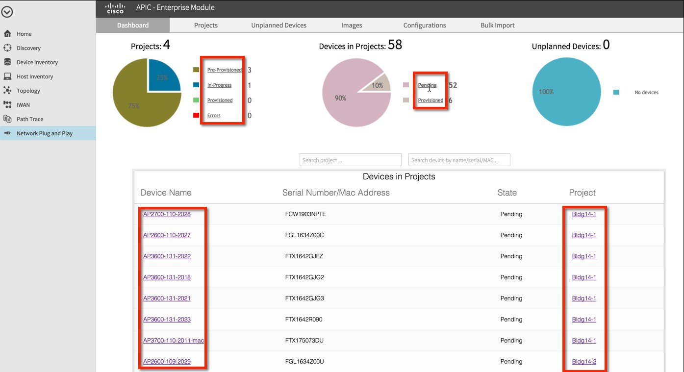
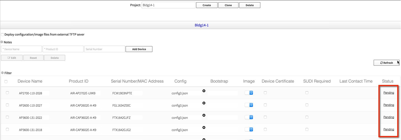
Step 1 Choose Network Plug and Play > Dashboard Step 2 Click on any of the Link next to the charts, e.g. Pending, Provisioned, Errors, etc. to view list of APs in relevant Projects. Step 3 Click on any of the AP or Project will take you to the Project view and APs.
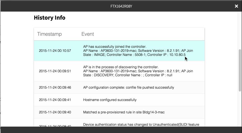
Step 4 Click on Status link will show detail of the PnP process.
Public Cloud Re-direction Service
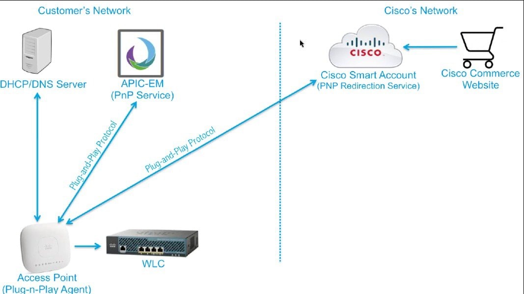
ProcedureCloud re-direction service uses Cisco public hosted cloud to easily automate deployment of PnP-capable devices. For wireless PnP with cloud, the minimal requirement is that the customer network needs DHCP and DNS, and connectivity reachable to Cisco public cloud.
A simple test would be to obtain DHCP address and ping ‘devicehelper.cisco.com’ from where the PnP-capable AP will be deployed.
AP network would also need to be reachable to target WLC (most simple), and APIC PnP server (optional if additional configuration is required).
This section describes only the cloud redirection steps for testing with PnP-capable AP to join a specific WLC defined on Cisco cloud service.
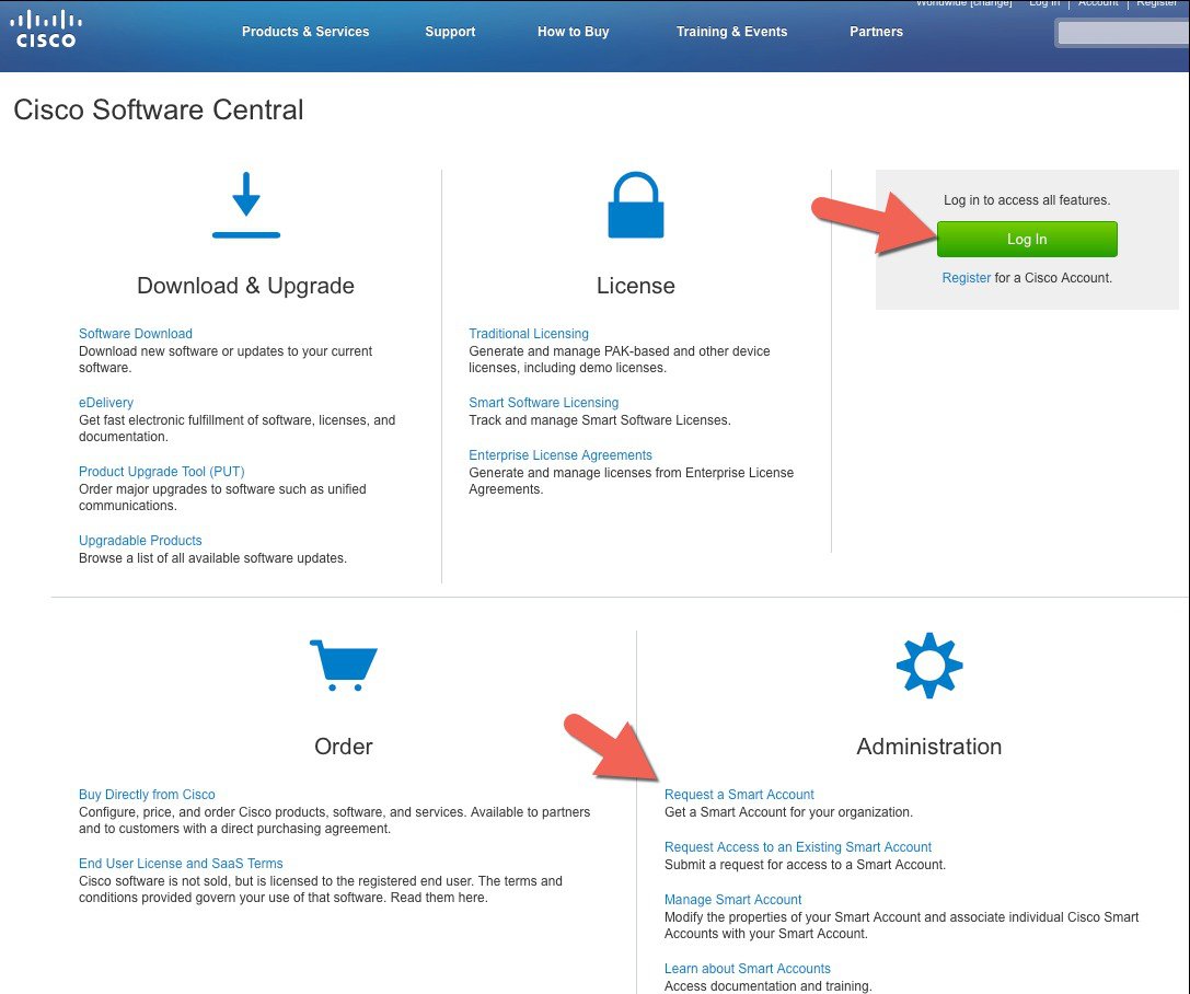
Step 1 Obtain a Smart Account access to Staging Cloud Redirection Network.
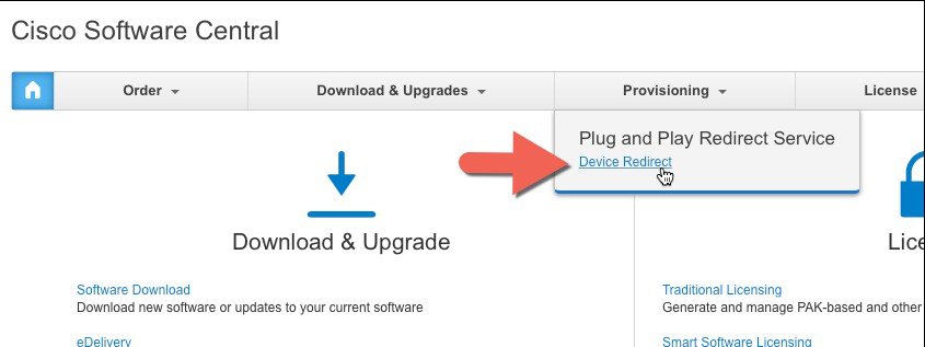
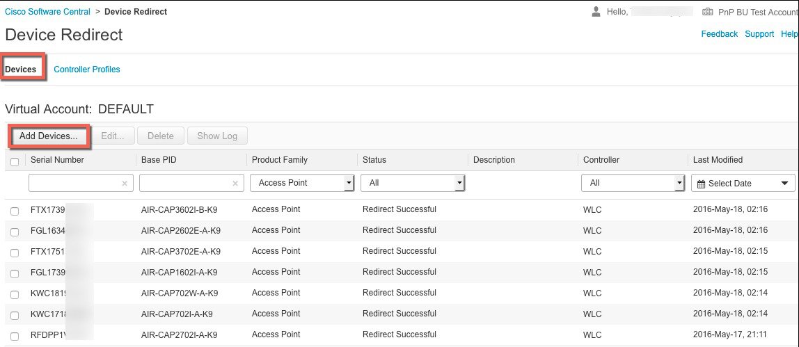
Step 2 Access the Plug and Play Redirect Service.
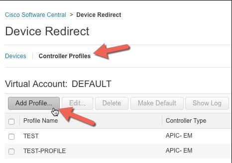
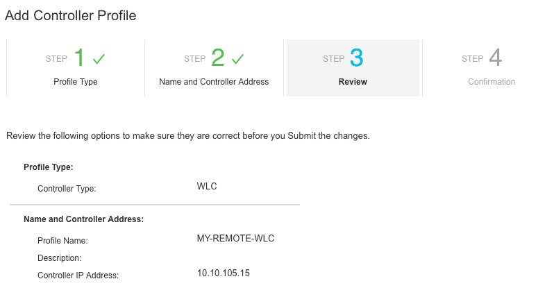
Step 3 Create a controller profile
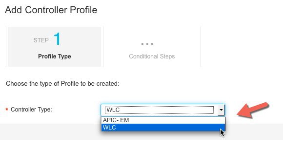
Specify controller profile using APIC-EM or WLC. In this example, WLC is selected to provision AP to a specific WLC. Click Next.
Note For cloud re-direction service testing to include APIC PnP, select APIC-EM instead of WLC.
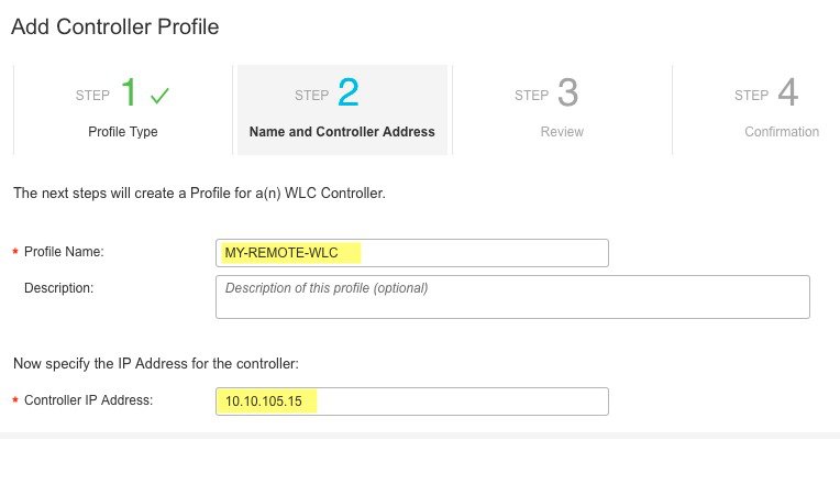
Enter a profile name and Controller IP address.
Review and click Submit.
Step 4 Provision the Access Point(s).
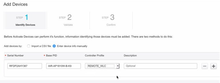
Specify each device’s Serial # and Base PID (please type it into the field).
Click + for each additional entry (multiple access points).
Choose a Controller Profile
Click + to add any additional access points.
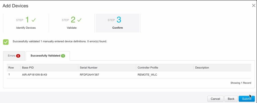
Validate for any errors then submit.
Step 5 Device Redirect page will now showing the device status as 'Pending'
If required, such as Controller Profile is using APIC-EM, provision the same access info on APIC EM server under Project page. See steps early in the guide that describe this process.
Step 6 Setup and configure local DHCP server, which will supply DHCP address to the device under test.
!
ip dhcp pool POOL
 network 1.2.3.0 255.255.255.0
 default-router 1.2.3.1
 domain-name cisco.com
 dns-server 172.1.2.3
!
Step 7 Setup DNS server
Step 8 PnP protocol will be using "time-pnp.cisco.com" and/or "pool.ntp.org" for time sync. Some lab networks block public NTP access, for such DNS mappings to local NTP server is needed. Step 9 Clear PnP-capable AP config and Reboot. In our example we have an AP previously joined to a remote WLC, navigate to the AP detail page and click clear All Config to reboot the AP and start the PnP process.
Step 10 From AP console, AP obtains IP address gateway and DNS.
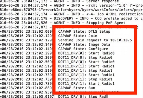
Step 11 Console continues discovery sequence (DHCP, DNS, CAPWAP, Cloud). This may take some time until AP PnP redirection completes.
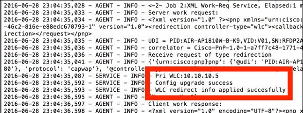
Step 12 Console output shows AP joining WLC (specified in controller profile).
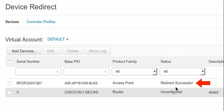
Step 13 From the cloud redirect dashboard (refresh if needed), device will show Redirect Successful.
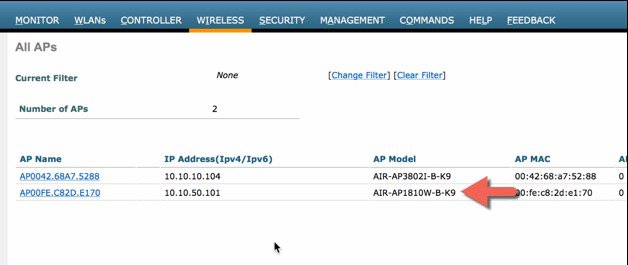
Step 14 Confirm this on the target WLC, AP will show on the list as joined and managed.
Copyright © 2016, Cisco Systems, Inc. All rights reserved.
Contact Cisco
- Open a Support Case

- (Requires a Cisco Service Contract)









 Feedback