Cisco Jabber on Cisco Wireless LAN
Scope
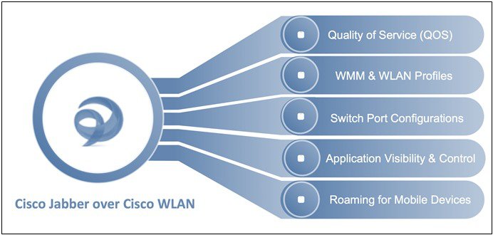
The purpose of this document is to serve as a design reference guide for wireless networks deployed to use Cisco Jabber over a Cisco Unified Infrastructure Wireless LAN (WLAN). The steps and explanations communicated in this document can be used as best practices for wireless deployments where Cisco Jabber is deployed as a prioritized business application over the wireless network. Cisco WLAN infrastructure and routers accurately classify and prioritize thousands of applications, including commonly deployed business critical applications such as Cisco Jabber, and Cisco WebEx, This Jabber design reference guide covers the recommended WLAN configuration steps for quality of service (QoS), Wireless Multi Media (WMM), WLAN Profiles, Switch Port Configurations, Application Visibility and Control (AVC), and Roaming for mobile devices.
Background
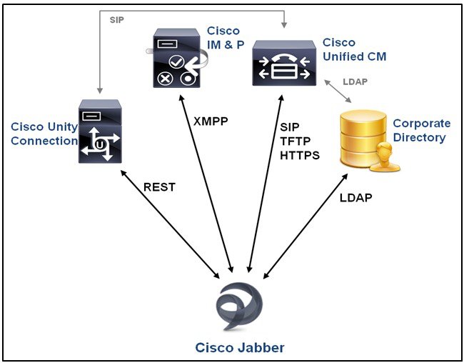
Cisco Jabber provides collaboration for multiple platforms including laptops, smartphones, and tablets with features like voice, video, instant messaging, telepresence, desktop sharing, and conferencing. One of the key features for Cisco Jabber is the Voice-Video communication that allows users to collaborate individually or as group conference using instant voice and video calling facility. In order to participate in voice, video and other forms of collaboration, Cisco Jabber clients has to integrate with Cisco Unified Communications Manager (Unified CM) server, Cisco Unity Connection, Cisco IM and Presence application servers as seen in the figure below
This reference guide assumes that you have deployed the back-end architecture successfully and tested it on multiple platforms to ensure successful basic communication for Jabber devices across wireless LAN user devices. Documents supporting the back-end architecture configuration and deployment are listed under For More Information’ section on page 17.
The Cisco Unified Wireless Network (UWN) WLAN technologies are compatible with this type of Cisco Unified Communications Architecture. UWN technology can also multiple communication managers and multiple wireless LAN controller (WLC) platforms in the same infrastructure. When operating in a large deployment with multiple controllers, the WLC-to-WLC connection options supports Layer 2 and Layer 3 Wi-Fi client roaming without call disruption. WLC hardware options provide access point connections from five access points on a single branch office WLC to 6000 access points on a single large enterprise WLC.
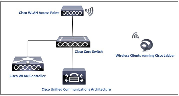
The wireless clients run jabber to communicate with the Unified Communications architecture through the access point. The WLAN data in a unified wireless network is typically tunneled between the AP and the WLAN controller through the Control and Provisioning of Wireless Access Points (CAPWAP) protocol. Since Jabber devices are dependent on the WLAN network for all communications, it becomes critical to tweak the WLAN network configurations to achieve the most optimal environment for a successful Jabber user experience.
Let’s go step by step to configure each design consideration for a Jabber deployment over a Cisco Unified WLAN Infrastructure.
Quality of Service Configuration
Wired and Wireless QoS
In order to achieve the most optimal results, especially for Jabber voice and video, it is crucial to implement the right quality of service. Ethernet and Wi-Fi share the concept of frame prioritization. Configuration options provide a means to maintain a packet’s priority across the wireless network. Wireless Wi-Fi traffic is identified by a service set identifier (SSID). Wi-Fi traffic can also display a prioritization value, expressed through User Priority (UP) tag present in the 802.11 header and is defined by the 802.11e amendment in 2005. This tag can receive any value from 0 to 7. Traffic with higher UP typically receives a more expedited treatment. The Wi-Fi Alliance ensures compatibility between vendors applying 802.11 QoS marking and prioritization through the Wi-Fi Multimedia (WMM) certification. The SSID configuration on the WLC defines the highest priority allowed for traffic forwarded to and from the WLAN.
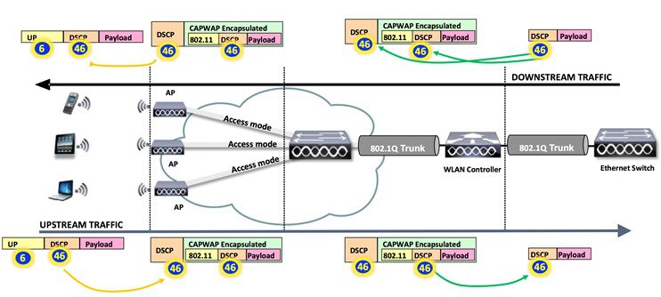
Inorder to maintain QoS over the wired network, QoS classification is applied to WLAN frames and this is a process in which mapping of classifications is done to and from the wired QoS marking and Wi-Fi QoS marking. For example, when prioritized traffic is send by a WLAN client, it has an IEEE 802.11 User Priority marking in the header. The AP needs to translate this classification into a Differentiated Services Code Point (DSCP) value for the wired CAPWAP packet carrying the frame, and this ensures that every packet is treated with appropriate priority on its way to the WLC. A similar process needs to occur on the WLC for CAPWAP packets going to the AP.
 Note |
In AireOS controller code 8.1 and prior, the above mentioned translation uses a static mapping table (from 8.1MR release, user can choose custom translation values). |
A mechanism to classify traffic from non-WMM clients is also required, so that their CAPWAP packets can also be given an appropriate QoS classification by the AP and the WLC.
Different vendors may use different translation mechanisms and values between Wi-Fi QoS marking and Wired QoS marking. Cisco uses the DSCP values (and does not limit marking to IP Precedence), following the IETF recommendations (for example: RFC 4594, which is the latest IETF guidelines on DCSP traffic marking) and the 802.11e mapping. As a result, we recommend using DSCP 46 for voice traffic, which translates 802.1p 5, to 802.11e 6.
Table 1 summarizes the applied marking for the main categories of traffic. summarizes the applied marking for the main categories of traffic.
|
Cisco 802.1p User Priority Traffic Type |
Cisco IP DSCP |
IEEE 802.11e/WMM User Priority |
|---|---|---|
|
Reserved (Network Control) |
56 (CS7) |
7 (unused) |
|
Reserved (CAPWAP) |
48 (CS6) |
— (unused) |
|
Voice |
46 (EF) |
6 |
|
Video |
34 (AF41) |
5 |
|
Voice Control (Signaling) |
24 (CS3) |
4 |
|
Background (Transactional/Interactive Data) |
18, 20, 22 (AF2x) |
3 |
|
Background (Bulk Data) |
10, 12, 14 (AF1x) |
2 |
|
Best Effort |
0 (BE) |
0 |
|
Background |
2, 4, 6 |
1 |
| Unknown DSCP from Wired | D | D >> 3 |
Note |
Any value not shown in the table would use the 3msb of the DSCP to derive the UP value. |
WLAN QoS – WMM
WLAN QoS is the result of joint efforts between Microsoft, Cisco, and IEEE to bring QoS to Wi-Fi channels. The IEEE ratified 802.11e amendment pertaining to QOS specification in the year 2005. The Wi-Fi Alliance certifies access point and the client QoS interoperability with a subset of the 802.11e specification known as Wi-Fi Multi-Media (WMM). All Wi-Fi data traffic with QoS capabilities have WMM QoS priority field (which is the UP value) inside the Wi-Fi packet header itself. Access points advertise their QoS capabilities in the same way they do for security capabilities through the Wi-Fi beacons and probe response frames. The QoS parameters for an SSID are contained in information elements of those frames.
The recommended WMM setting for the WLAN catering to the Jabber devices is ‘Required’. This ensures WMM participation from all devices running Jabber, and at the same time keeps non-WMM clients from connecting to the SSID. Legacy clients such as handheld data transaction computers and old laptop computers can be allowed, but use lower level QoS. Smartphones, tablets, and devices that are 802.11n/ac are WMM compliant, as WMM is a mandatory feature for 802.11n and 802.11ac. 802.11g client devices may or may not support WMM. Although the applications running on the devices may not be marking DSCP, or the operating system may not allow WMM QoS marking, but the devices still use the WMM/802.11e header format when transmitting or receiving Wi-Fi traffic. Various policies on the WLC can be established to define the handling of QoS markings at the WLC.
Choose WLAN > QoS and select Required as the WMM setting.
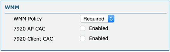
Note |
Non-WMM clients will not be able to connect to a WLAN which is set to have WMM Policy as ‘Required’. To support Non-WMM clients, a separate SSID/WLAN is recommended to allow connectivity to the network. |
We recommend that WMM and DSCP marking must be enabled on the Wi-Fi devices. The network hop from the Wi-Fi endpoint device to the access point is the most important hop in the network for maintaining a user-acceptable mean opinion score (MOS) value. Once the Wi-Fi client’s transactions are received at the access point, the QoS policies on the WLC can control the marking or dropping of the packets.
WLAN QoS – WLAN Profiles
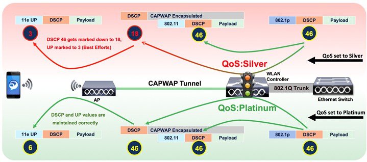
From the Cisco WLAN Controller user interface, you can assign a QoS profile (Platinum, Gold, Silver, and Bronze) to each SSID. This profile determines the highest QoS level expected and allowed to exchange on this SSID. The role of a QoS profile is to set the ceiling (the maximum level of QoS that clients are allowed to use). For example, if you set a silver profile on a WLAN, clients can send background traffic or best effort traffic, and any traffic marked with a higher QoS value (say Voice or Video) will be down-marked to Silver (BE, DSCP 18). The profile also determines what marking behavior should be used for incoming non-WMM traffic, traffic without a DSCP marking, and for multicast traffic. When incoming traffic exceeds the maximum QoS value of the profile, the traffic is remarked to match the maximum QoS value assigned to the profile (Please refer to the WLAN QOS Parameters section on page 6 for more details on how to configure the maximum QOS values for each profile)
Similarly, if you set platinum, the clients are allowed to use any QoS tag/class. This does not mean that everything is considered as voice. It means that, if the laptop sends voice traffic, it is treated as such, and, if the laptop sends best effort (as the majority of laptops send), it is also treated as best effort.
By default the QOS profiles comply with the following priority mechanism:
|
QoS Profile |
Traffic Adaptability Level |
Traffic Limitation Level |
Maximum Expected QoS Level |
|---|---|---|---|
|
Platinum |
All Traffic, including Real-time Voice Traffic |
None |
DSCP-46 and UP-6 |
|
Gold |
All Traffic, including Real-Time Video Traffic |
Not intended for Real-Time Voice Traffic |
DSCP-34 and UP-5 |
|
Silver |
All Transactional and Data Traffic |
Not intended for Real-Time Voice and/or Video Traffic |
DSCP-18 and UP-3 |
|
Bronze |
All Background Traffic |
Not intended for Real-Time, Transactional and/or Data Traffic |
DCSP-10 and UP-1 |
These profiles are available to configure on the WLAN > QoS tab. Silver (best effort) QoS profile is enabled by default.
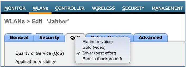
-
Choose WLAN > QoS tab, click Platinum (voice) as the Quality of Service (QoS).
Cisco Jabber includes services ranging from file transfer and application sharing to real audio and video communications. Real time audio communication traffic is very sensitive to delays and losses, and is typically assigned a higher priority than other traffic. As a result, the Wi-Fi WLAN QoS level recommended for Jabber clients is a QoS level of Platinum. The Platinum QoS priority level allows forwarding of all prioritized traffic up to the voice category.
The following illustration shows an example of how a Jabber Voice call QoS Marking (AP to Client) takes place under different profiles.
Generally the WLAN/SSID used for Jabber devices is a hybrid WLAN (also used for other devices/applications besides Jabber). In such cases, customizing the maximum priorities for the QoS profiles is an important step to avoid any non-marked or incorrectly marked best-effort traffic to get prioritized as voice/video. For example, by default all the non-WMM traffic gets the maximum DSCP value of the profile, so undesired prioritization (Voice priority) for such traffic may occur when the WLAN QoS profile is set to Platinum
The individual QoS profile settings are available on the Wireless > QoS tab.
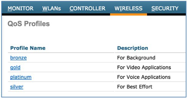
Setting the WLAN QoS parameters allows additional configuration to granularly handle unmarked or unknown traffic on the WLAN where the Jabber devices communicate.
-
Choose Wireless > QoS > Profiles > Platinum tab, select besteffort for Unicast Default Priority and Multicast Default Priority.
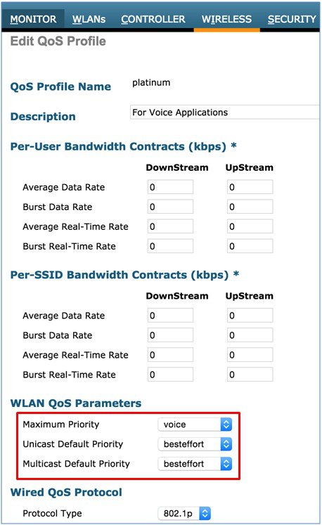
The unicast default priority is allotted to any incoming unknown traffic marking. This setting decides on what should be done for traffic for non-WMM traffic or traffic with unknown marking. Setting the unicast default priority and multicast default priority to best effort will prevent the undesired prioritization on the WLAN.
Note |
The Wired QoS Protocol option for 802.1p tagging is only recommended when you can’t trust the DSCP on the switch. |
Cisco Switch Port Configuration for APs and WLCs
The wired side of the infrastructure also needs to be compatible with the DSCP honoring to allow a complete end to end priority structure. The QoS configuration of the switch port connecting the access point should trust the DSCP of the CAPWAP packets that are passed to it from the access point. There is no class-of-service (CoS) marking on the CAPWAP frames coming from the access point. The following is an example of the switchport configuration.
Note |
This configuration addresses only the classification and queuing commands that can be added depending on local QoS policy. |
interface
GigabitEthernet1/0/1
switchport access vlan 100
switchport mode access
mls qos trust dscp
spanning-tree
portfast end
In trusting the access point DSCP values, the access switch trusts the policy set for that access point by the WLC. The maximum DSCP value assigned to client traffic is based on the QoS policy applied to the WLAN on that access point.
AVC – Application Visibility and Control
Cisco’s Application Visibility and Control (AVC) classifies applications using deep packet inspection techniques with the Network-Based Application Recognition (NBAR) engine, and provides application-level visibility and control into Wi-Fi networks. The recognition of business applications are supported with AVC protocol pack 6.4 and above, operating with next-generation Network-Based Application Recognition (NBAR2) engine 13 and above. With this capability, you can correctly identify Cisco Jabber and also sub-classify how much of your traffic is data (desktop share), audio, video, and apply different policies accordingly.
After the applications are recognized, the AVC feature enables you to either drop, mark, or rate-limit (by direction) the data traffic. Even if DSCP is already set, there is a value of AVC providing visibility to the traffic that it classifies. Using AVC, the controller can detect more than 1000 applications. AVC enables you to perform real-time analysis and create policies to reduce network congestion, costly network link usage, and infrastructure upgrades.
The QoS Behavior with AVC between AP, WLC, and Infrastructure:
Upstream
-
A frame is transmitted with or without inner packet DSCP (or UP Value) from the wireless side (client device).
-
On the AireOS solution, the receiving access point translates the 802.11e UP value in the frame header into a DSCP value using Table 1 and capping the value to the QoS profile used for the SSID. CAPWAP is used to encapsulate the 802.11 frame. The CAPWAP encapsulated packet is transmitted to the WLC. The outer CAPWAP header contains the DSCP value translated from the 802.11e UP value (and capped if necessary). The inner encapsulated packet contains the original DSCP value applied by the wireless client. If UP value on the upstream frame is missing, then capwap gets DSCP 0.
-
The WLC removes the CAPWAP header.
-
The AVC module on the WLC, which is optional, can be used to overwrite the original DSCP value of the source packet to the configured value in the AVC profile. The WLC then reads the QoS profile associated to the SSID, and caps the 802.1p value to the maximum allowed by the QoS profile, while the DSCP value stays uncapped. The WLC then forwards the source packet with its remarked DSCP value to the destination address.
Downstream
-
A packet comes from a switch with or without an inner-DSCP wired-side value.
-
The optional AVC module is used to overwrite the inner-DSCP value of the downstream source packet.
-
The WLC sends out the packet to the access point with QoS priority (CoS and DSCP) on the outer CAPWAP header. This value is no higher than the QoS priority configured on the WLAN.
-
The access point uses the outer DSCP header value to determine the priority, and sends the packet on air with a WMM UP value representative of the DSCP setting, or the WLAN configuration if the WLAN setting is lower. The original DCSP value remains unchanged.
For more information, see Table 1.
Note |
The WLAN QoS configuration sets the highest priority for which a packet in the WLAN may be forwarded. For example, a WLAN with a QoS priority of ‘gold’ will forward audio & voice packets at a downgraded video priority, demoting the DSCP value from 46 to 34. |
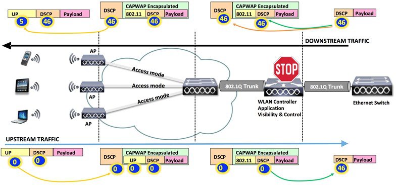
When Jabber traffic reaches the wireless controller, the controller performs deep packet inspection to recognize the flow. If the flow is recognized as an application part of the AVC profile, the traffic is marked according to the AVC policy. For example, in situations where a wireless client sends unmarked Jabber traffic, this traffic upon reaching the WLAN Controller would get immediately recognized by the NBAR engine, and get remarked according to the AVC profile. If the AVC profile was set to UP mark with DSCP value 46, the flows would be as in the following figure:
Recommended AVC Configuration for Cisco Jabber Audio and Video
Cisco Jabber offers several types of services: File transfer, application sharing, SIP signaling, real time audio, and real time video communications. Microsoft commonly recommends DSCP 40 or 46 for real time voice, DSCP 34 for video, and 24 for the other services. This section focuses on configuring AVC for Jabber audio and video. This configuration section is targeted only towards the Jabber traffic on the WLAN profile. The rest of the traffic could of course be allowed on the WLAN (and prioritized similarly), but assuming the marking for rest of the traffic is untouched and do not exceed the qos profile maximum. To configure AVC for Cisco Jabber traffic, perform the following steps:
Procedure
|
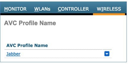
Step 1 |
Create a new profile for Jabber by choosingWireless > Application Visibility and Control > AVC Profiles
|
|
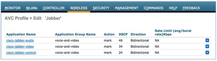
Step 2 |
Add a specific Jabber application packet type for remarking the DSCP value for that packet type.
This sample profile uses three pre-defined application names (these are found in the AVC database) that fingerprint the secure Jabber audio, video, and control-data packets. |
|
Step 3 |
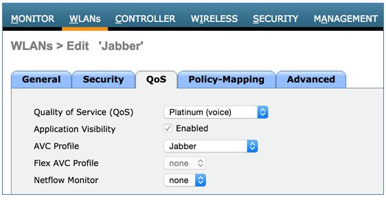
Enable Application Visibility on the WLAN, and set the Jabber specific profile as the AVC Profile.
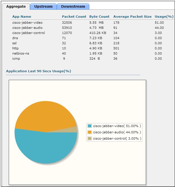
Now with AVC enabled and the Jabber AVC profile set, the Cisco controller has complete visibility and traffic control for all Jabber traffic in this WLAN. To test your configuration, associate multiple Jabber devices to the Jabber WLAN and initiate voice and video calls on the network. Below is an example to illustrate Jabber traffic visibility on the controller dashboard under Monitor > Applications for a Jabber video call between two Wi-Fi endpoints.
Other applications can also be included in the same Jabber profile and then have their QoS priorities managed in a similar fashion as the examples for audio and video. |
Roaming Enhancements for Mobile Devices
Note |
You must enable 802.11r and 802.11k on WLAN to connect with the supporting mobile devices. If the device does not support 802.11r, you may not get connected with the WLAN. For more information about the device support for 802.11r, 802.11k, and 802.11v, refer Device Classification Guide. |
802.11r (Fast roaming) is an enhancement to allow the initial Client-AP handshake with the new AP which is done even before the client roams to the target AP, referred as Fast Transition (FT). FT eliminates considerable handshaking overhead while roaming, that reduce the handoff time between APs while providing security and QoS. FT is useful for client devices that have delay-sensitive applications such as voice and video, and acts as key requirement for voice over Wi-Fi. Maximum handoff time is 20 milliseconds (ms) for smart clients.
Configuring 802.11r Fast Transition Roaming
To configure 802.11r fast transition roaming using the controller user interface, perform the following steps:
Procedure
|
Step 1 |
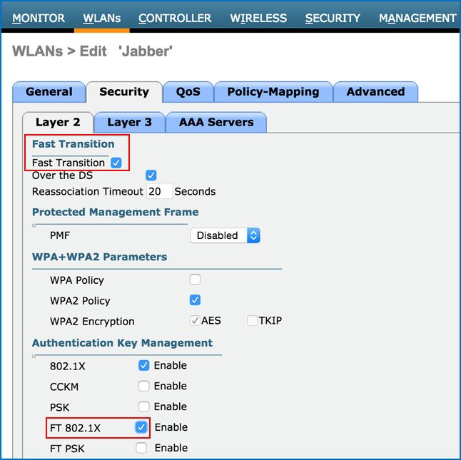
Choose WLAN > Security > Layer 2 tab. |
||
|
Step 2 |
Check the Fast Transition check box.
|
||
|
Step 3 |
Set the Layer 2 security as WPA+WPA 2 or Open. |
||
|
Step 4 |
Enable FT for the respective Authentication Key Management.
The time between FT Authentication Request and Re-association Request time must not exceed the Re-association Timeout. |
Configuring 802.11k Neighbor List
802.11k facilitates roaming by allowing the 802.11k clients, associated with an AP to a request for a list of neighbor APs. The request is in the form of an 802.11 management frame known as an action frame. The AP responds with a list of neighbor APs on the same WLAN with their Wi-Fi channel numbers. The AP response also acts as an action frame. Using the 802.11k response frame, it can recognize the APs as candidates for next roaming. The use of 802.11k radio resource management (RRM) processes allows the client to significantly reduce the overall neighbor AP scanning period, when deciding the next best available AP.
To configure 802.11k neighbor list for roaming (Version 8.1 and above), perform the following steps:
Procedure
|
Step 1 |
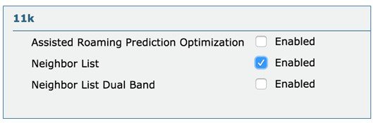
Choose WLAN > Advanced. |
|
Step 2 |
Enable Neighbor List under the 11k configuration section area.
|
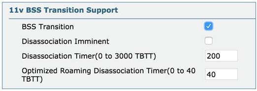
Configuring 802.11v BSS Transition Support
802.11v Basic Service Set (BSS) Transition Management is a part of the Wireless Network Management (WNM) feature which acts as a platform for the clients. 802.11v BSS Transition Management provides the infrastructure to potentially exchange operational information, so that both sides can have additional awareness of the WLAN conditions. 802.11v offers Network Assisted Roaming enhancement for the client devices where the AP tries to assist in the roaming decision making, by providing an unsolicited recommendation as a request to the client. This request contains the suggestion for the best available AP that the client can potentially roam to. The client can always choose whether to accept or reject the advice offered by the AP, which helps to implement a firm foundation for self-correcting events and actions.
To configure 802.11v BSS transition support (Version 8.1 and above), perform the following steps:
Procedure
|
Step 1 |
ChooseWLAN > Advanced. |
|
Step 2 |
Enable BSS Transition in the 11v BSS Transition Support area.
|
Summary
We recommend constant monitoring of Wi-Fi channel conditions to avoid interference, disruptions caused by rogue devices, and spectrum issues.
The overall WLAN design should consider configuration of multicast direct as well as Wi-Fi call admission control for Jabber voice and video.
In addition, technologies such as Cisco CleanAir, ClientLink, and radio resource management (RRM) allows you to optimize your network performance while simultaneously reducing the coverage holes and bypassing interference.
To provide an enterprise solution and a high-quality user experience for Jabber users, We recommend that the WLANs used for Jabber communication be created with the following best practices:
- WLAN QoS equal to platinum,
which allows the clients to use any QoS tag/class
-
Adding QoS service profiles when appropriate.
-
Adding QoS service roles when appropriate.
-
-
Appropriate WMM and WLAN Profiles configurations where required.
-
Enabling AVC to correctly classify Cisco Jabber application. Creating priority specific AVC Profile to allow individual prioritization for Jabber traffic using the appropriate QoS treatments, and finally enabling the AVC profile to the WLAN.
-
Ensuring the correct switch port configurations to honor the incoming and outgoing traffic DSCP markings.
-
WLAN band select to push clients to the 5 GHz band, where coverage design supports voice and VoWLAN.
-
WLAN 802.1x security
-
Adding fast transition (11r) for supported clients when appropriate to improve re-authentication roams.
-
-
802.11k for supported clients to provide access point neighbor lists based on client location for network-assisted roaming.
-
802.11v for supported clients to offer Network Assisted Roaming enhancement for the client devices where the AP will try to assist in the roaming decisions.
-
Disabled access point load balance.
-
Enabled channel scan at defaults.
The best practices for WLANs also includes deploying highly-available WLCs, in conjunction with high-density of access points to promote always-available WLAN infrastructure.
In addition, Cisco’s HDX suite of technologies such as Cisco CleanAir, ClientLink, and Radio Resource Management automatically allows to optimize your network performance while simultaneously reducing coverage holes and bypassing interference.
For More Information
For more information refer to the following Cisco online references:
Cisco WLC Best Practices including 802.11k, 802.11r
-
Cisco Wireless LAN Controller Configuration Best Practices (Updated July 2015)
http://www.cisco.com/c/en/us/td/docs/wireless/technology/wlc/8-1/82463-wlc-config-best-practice.html
Cisco Device Classification Guide for 802.11k, 802.11r, 802.11v Support
-
Cisco Device Classification Guide (Updated May 2015)
Cisco Validated Designs and Solution Reference Network Design (SRND)
-
The Cisco Design Zone website contains the primary library of solution guides for Collaboration, Enterprise Networks, Mobility, and technologies:
http://www.cisco.com/c/en/us/solutions/enterprise/unified-communication-system/index.html-
The Cisco Real-Time over Wireless LAN Design Guide is listed under Collaboration.
-
The Overall Mobility Design is listed under Design Zone for Mobility.
-
AVC – Application Visibility and Control
-
Cisco Application Visibility and Control (AVC) Q&A
-
Configuring Application Visibility and Control (WLC 7.6 or later)
Cisco Unified Communications
-
Cisco Communities: Unified Communications
https://communities.cisco.com/community/technology/collaboration/uc
 Feedback