Layer 2 Security
This section contains the following subsections:
Prerequisites for Layer 2 Security
WLANs with the same SSID must have unique Layer 2 security policies so that clients can make a WLAN selection based on the information advertised in beacon and probe responses. The available Layer 2 security policies are as follows:
-
None (open WLAN)
-
Static WEP or 802.1X

Note
-
Because static WEP and 802.1X are both advertised by the same bit in beacon and probe responses, they cannot be differentiated by clients. Therefore, they cannot both be used by multiple WLANs with the same SSID.
-
WLAN WEP is not supported in Cisco Aironet 1810w Access Points.
-
-
WPA+WPA2
Note
-
Although WPA and WPA2 cannot be used by multiple WLANs with the same SSID, you can configure two WLANs with the same SSID with WPA/TKIP with PSK and Wi-Fi Protected Access (WPA)/Temporal Key Integrity Protocol (TKIP) with 802.1X, or with WPA/TKIP with 802.1X or WPA/AES with 802.1X.
-
A WLAN configured with TKIP support will not be enabled on an RM3000AC module.
-
-
Static WEP (not supported on Wave 2 APs)
Guidelines and Limitations
-
If WLAN is configured with Layer 2 security WEP without an encryption key, you will receive the following XML message:
apf_xml_validate_vapStatus: Encryption mode 0 for static WEP does not match encryption mode 2 for dynamic WEP Validation for node ptr_apfCfgData.apfVAPIDData.apfVapStatus failed, indices for node are 11 -
If you need Layer 2 protection and prevent MAC spoofing, we recommend that you combine web authentication with Layer 2 security such as WPA2-PSK or WPA2-dot1x.
Configuring Dynamic 802.1X Keys and Authorization (CLI)
Controllers can control 802.1X dynamic WEP keys using Extensible Authentication Protocol (EAP) across access points and support 802.1X dynamic key settings for WLANs.
Note |
To use LEAP with lightweight access points and wireless clients, make sure to choose Cisco-Aironet as the RADIUS server type when configuring the CiscoSecure Access Control Server (ACS). |
-
Check the security settings of each WLAN by entering this command:
show wlan wlan_id
The default security setting for new WLANs is 802.1X with dynamic keys enabled. To maintain robust Layer 2 security, leave 802.1X configured on your WLANs.
-
Disable or enable the 802.1X authentication by entering this command:
config wlan security 802.1X {enable | disable} wlan_id
After you enable 802.1X authentication, the controller sends EAP authentication packets between the wireless client and the authentication server. This command allows all EAP-type packets to be sent to and from the controller.
Note
The controller performs both web authentication and 802.1X authentication in the same WLAN. The clients are initially authenticated with 802.1X. After a successful authentication, the client must provide the web authentication credentials. After a successful web authentication, the client is moved to the run state.
-
Change the 802.1X encryption level for a WLAN by entering this command:
config wlan security 802.1X encryption wlan_id [0 | 40 | 104]
-
Use the 0 option to specify no 802.1X encryption.
-
Use the 40 option to specify 40/64-bit encryption.
-
Use the 104 option to specify 104/128-bit encryption. (This is the default encryption setting.)
-
RADIUS VSA
The Internet Engineering Task Force (IETF) draft standard specifies a method for communicating vendor-specific information between the network access server and the RADIUS server by using vendor specific attributes (VSA). VSA allow vendors to support their own extended attributes otherwise not suitable for general use. VSA are predefined in an XML file. You need to add the vendor specific attributes to the XML file and this XML file is downloaded to the controller. There is no configuration required on the controller to enable the support. The file contains the RADIUS attributes in a specific format as explained by the XML schema to specify the XML tags.
The XML file with the vendor specific attributes defined can be downloaded from a FTP server. The downloaded file is stored in the flash memory and retained across several reboot processes. The file is parsed upon successful download and each time when the controller boots up. The XML file can be uploaded to RADIUS server for authentication and accounting. Once controller parses these values, it stores the file in a separate data structures meant for vendor specific attributes storage. The controller uses these attributes value in authentication or accounting packets, or both based on specified usage format. If there are any errors in the file, the controller parsing fails, and the attributes are not applied. You should address the errors in the file or download the file from the FTP server again to the controller.
This section contains the following subsections:
Sample RADIUS AVP List XML File
You can use the sample RADIUS AVP list XML file for reference. The sample XML file contains only two attributes, one for authentication and the other for accounting. You can add more number of RADIUS attributes and value pairs but those attributes and value pairs should be appended in the format specified.
Note |
The maximum number of WLANs that is supported in an AVP download is 32. |
<?xml version="1.0" encoding="UTF-8"?>
<!--Sample XML file edited by User1-->

<radiusFile>
<avpList SSID_PROF="test" incAuth="true" incAcct="false">
        <radiusAttributes>
                <attributeName>Idle-Timeout</attributeName>
                <vendorId>9</vendorId>
                <attributeId>21</attributeId>
                <valueType>INTEGER</valueType>
                <attributeValue>100</attributeValue>
        </radiusAttributes>
        <radiusAttributes>
                <attributeName>remote-name</attributeName>
                <vendorId>9</vendorId>
                <attributeId>26</attributeId>
                <valueType>STRING</valueType>
                <attributeValue>TEST</attributeValue>
        </radiusAttributes>
</avpList>
<avpList SSID_PROF="test" incAcct="true">
        <radiusAttributes>
                <attributeName>Idle-Timeout</attributeName>
                <vendorId>9</vendorId>
                <attributeId>21</attributeId>
                <valueType>INTEGER</valueType>
                <attributeValue>100</attributeValue>
        </radiusAttributes>
        <radiusAttributes>
                <attributeName>remote-name</attributeName>
                <vendorId>9</vendorId>
                <attributeId>26</attributeId>
                <valueType>STRING</valueType>
                <attributeValue>TEST</attributeValue>
        </radiusAttributes>
</avpList>
</radiusFile>
Downloading RADIUS AVP List (GUI)
Procedure
| Step 1 |
Choose Commands > Download File to open the Download File to Controller page. |
| Step 2 |
From the File Type drop-down list, choose RADIUS AVP List. |
| Step 3 |
From the Transfer Mode drop-down list, choose from the following options:
|
| Step 4 |
In the IP Address text box, enter the IPv4 or IPv6 address of the server. |
| Step 5 |
In the File Path text box, enter the directory path of the RADIUS AVP list. |
| Step 6 |
In the File Name text box, enter the name of the RADIUS AVP list. |
| Step 7 |
If you are using an FTP server, follow these steps:
|
| Step 8 |
Click Download to download the RADIUS AVP list to the controller. A message appears indicating the status of the download. |
| Step 9 |
Choose to open the Download RADIUS AVP List page. |
| Step 10 |
From the WLAN SSID Profile name drop-down list, choose the WLAN SSID profile name. |
| Step 11 |
Click the Auth AVP tab to view the RADIUS authentication attributes mapped to the AVP list. |
| Step 12 |
Click the Acct AVP tab to view the RADIUS accounting attributes mapped to the AVP list. |
Uploading RADIUS AVP List (GUI)
Procedure
| Step 1 |
Choose to open the Upload File from Controller page. |
| Step 2 |
From the File Type drop-down list, choose RADIUS AVP List. |
| Step 3 |
From the Transfer Mode drop-down list, choose from the following options:
|
| Step 4 |
In the IP Address text box, enter the IPv4 or IPv6 address of the server. |
| Step 5 |
In the File Path text box, enter the directory path of the RADIUS AVP list. |
| Step 6 |
In the File Name text box, enter the name of the RADIUS AVP list. |
| Step 7 |
If you are using an FTP server, follow these steps:
|
| Step 8 |
Click Upload to upload the RADIUS AVP list from the controller. A message appears indicating the status of the upload. |
Uploading and Downloading RADIUS AVP List (CLI)
Procedure
| Step 1 |
Log on to the controller CLI. |
| Step 2 |
Download the RADIUS AVPs in the XML file format from the FTP server to the controller by entering this command: |
| Step 3 |
Upload the XML file from the controller to the RADIUS server using the command: transfer upload datatype radius-avplist |
| Step 4 |
Display VSA AVPs using the command: show radius avp-list ssid-profile-name |
Custom NAS-ID for RADIUS Accounting Using Downloadable RADIUS AVP
This feature addresses the need to have a configurable custom NAS-ID for custom accounting purposes on per WLAN basis. To download the XML file to the Cisco WLC, you can use the FTP (server) method or use the transfer download method. This file is retained in the WLC after the reboot also.
The custom AVP supersedes only the WLAN NAS-ID in the accounting messages. The priority of the other NAS-IDs is not affected.
Note |
|
Refer to RADIUS VSA section from the WLC Configuration guide to create the custom AVP file.
The following are the supported value type for NAS-ID (strictly uppercase):
-
SYSNAME
-
SYSIP
-
SYSMAC
-
APIP
-
APNAME
-
APMAC
-
APETHMAC
-
APGROUP
-
FLEXGROUP
-
SSID
-
APLOCATION
Note |
Software downgrade from the 8.6 to older version will not be supported for the new NAS-identifier AVP. If you decide to downgrade to an older version, perform the following steps:
|
Restrictions on Custom NAS-ID for RADIUS Accounting Using Downloadable RADIUS AVP
-
The custom NAS-ID string should contain minimum one value type and a maximum of three value type using ":" as the delimiter.
-
When a downloaded NAS-ID has multiple custom NAS-ID syntaxes for the same SSID profile, by default the latest syntax is used after overwriting the older one.
-
Maximum number of downloadable WLAN SSID profiles are 32.
-
The maximum supported length of the custom NAS-IDs that are derived from the syntax is 253.
This section contains the following subsections:
Configuring Custom NAS-ID AVP XML File
Procedure
| Step 1 |
Edit the XML file using a notepad. |
||
| Step 2 |
Update the SSID_PROF tag with the WLAN profile name you wish to apply the AVP to. |
||
| Step 3 |
Update the following fields:
Example: |
||
| Step 4 |
Download the updated AVP XML file to the WLC. |
||
| Step 5 |
When the RADIUS download fails, use debug option debug radius avp-xml enable to know more about the error. |
Deleting a NAS-ID AVP (GUI)
Procedure
| Step 1 |
Edit the AVP XML file using a text editor and delete the SSID_PROF name. |
||
| Step 2 |
Download the updated NAS-ID AVP XML file to the Cisco WLC. |
||
| Step 3 |
Choose . On the DOWNLOADED RADIUS AVP LIST page, the Acct tab displays an empty page. The NAS-ID AVP is successfully deleted.
|
Viewing Custom NAS-ID Enhancement Configuration (GUI)
Procedure
| Step 1 |
Choose to open the WLAN > Edit page. |
||||||
| Step 2 |
In the general tab, view the greyed out NAS-ID field to view the value type. Check if the format syntax for that file is downloaded and the string is displayed. Example:
|
||||||
| Step 3 |
Choose tab to open the DOWNLOADED RADIUS AVP LIST page. |
||||||
| Step 4 |
Select the Wlan SSID Profile Name from the drop-down list. The AVP details are displayed. |
Viewing Custom NAS-ID Enhancement (CLI)
Procedure
Identity Networking
In most wireless LAN systems, each WLAN has a static policy that applies to all clients associated with an SSID. Although powerful, this method has limitations because it requires clients to associate with different SSIDs to inherit different QoS and security policies.
However, the Cisco Wireless LAN solution supports identity networking, which allows the network to advertise a single SSID but allows specific users to inherit different QoS or security policies based on their user profiles. The specific policies that you can control using identity networking are as follows:
-
ACL—When the ACL attribute is present in the RADIUS Access Accept, the system applies the ACL name to the client station after it authenticates, which overrides any ACLs that are assigned to the interface.
-
VLAN—When a VLAN Interface-name or VLAN tag is present in a RADIUS Access Accept, the system places the client on a specific interface.
Note
The VLAN feature only supports MAC filtering, 802.1X, and WPA. The VLAN feature does not support web authentication or IPsec.
-
Tunnel Attributes.
Note
When any of the other RADIUS attributes (QoS-Level, ACL-Name, Interface-Name, or VLAN-Tag), which are described later in this section, are returned, the Tunnel Attributes must also be returned.
The operating system’s local MAC filter database has been extended to include the interface name, allowing local MAC filters to specify to which interface the client should be assigned. A separate RADIUS server can also be used, but the RADIUS server must be defined using the Security menus.
This section contains the following subsection:
RADIUS Attributes Used in Identity Networking
QoS-Level
This section explains the RADIUS attributes used in identity networking.
This attribute indicates the QoS level to be applied to the mobile client's traffic within the switching fabric, as well as over the air. This example shows a summary of the QoS-Level Attribute format. The text boxes are transmitted from left to right.
 0                   1                   2                   3
 0 1 2 3 4 5 6 7 8 9 0 1 2 3 4 5 6 7 8 9 0 1 2 3 4 5 6 7 8 9 0 1
+-+-+-+-+-+-+-+-+-+-+-+-+-+-+-+-+-+-+-+-+-+-+-+-+-+-+-+-+-+-+-+-+
|     Type      |  Length       |            Vendor-Id
+-+-+-+-+-+-+-+-+-+-+-+-+-+-+-+-+-+-+-+-+-+-+-+-+-+-+-+-+-+-+-+-+
     Vendor-Id (cont.)          | Vendor type   | Vendor length |
+-+-+-+-+-+-+-+-+-+-+-+-+-+-+-+-+-+-+-+-+-+-+-+-+-+-+-+-+-+-+-+-+
|                           QoS Level                           |
+-+-+-+-+-+-+-+-+-+-+-+-+-+-+-+-+-+-+-+-+-+-+-+-+-+-+-+-+-+-+-+-+
-
Type – 26 for Vendor-Specific
-
Length – 10
-
Vendor-Id – 14179
-
Vendor type – 2
-
Vendor length – 4
-
Value – Three octets:
-
3 – Bronze (Background)
-
0 – Silver (Best Effort)
-
1 – Gold (Video)
-
2 – Platinum (Voice)
-
ACL-Name
This attribute indicates the ACL name to be applied to the client. A summary of the ACL-Name Attribute format is shown below. The text boxes are transmitted from left to right.
 0                   1                   2                   3
 0 1 2 3 4 5 6 7 8 9 0 1 2 3 4 5 6 7 8 9 0 1 2 3 4 5 6 7 8 9 0 1
+-+-+-+-+-+-+-+-+-+-+-+-+-+-+-+-+-+-+-+-+-+-+-+-+-+-+-+-+-+-+-+-+
|     Type      |  Length       |            Vendor-Id
+-+-+-+-+-+-+-+-+-+-+-+-+-+-+-+-+-+-+-+-+-+-+-+-+-+-+-+-+-+-+-+-+
     Vendor-Id (cont.)          | Vendor type   | Vendor length |
+-+-+-+-+-+-+-+-+-+-+-+-+-+-+-+-+-+-+-+-+-+-+-+-+-+-+-+-+-+-+-+-+
|        ACL Name...
+-+-+-+-+-+-+-+-+-+-+-+-+-+-+-
-
Type – 26 for Vendor-Specific
-
Length – >7
-
Vendor-Id – 14179
-
Vendor type – 6
-
Vendor length – >0
-
Value – A string that includes the name of the ACL to use for the client
Interface Name
This attribute indicates the VLAN Interface a client is to be associated to. A summary of the Interface-Name Attribute format is shown below. The text boxes are transmitted from left to right.
 0                   1                   2                   3
 0 1 2 3 4 5 6 7 8 9 0 1 2 3 4 5 6 7 8 9 0 1 2 3 4 5 6 7 8 9 0 1
+-+-+-+-+-+-+-+-+-+-+-+-+-+-+-+-+-+-+-+-+-+-+-+-+-+-+-+-+-+-+-+-+
|     Type      |  Length       |            Vendor-Id
+-+-+-+-+-+-+-+-+-+-+-+-+-+-+-+-+-+-+-+-+-+-+-+-+-+-+-+-+-+-+-+-+
     Vendor-Id (cont.)          |  Vendor type  | Vendor length |
+-+-+-+-+-+-+-+-+-+-+-+-+-+-+-+-+-+-+-+-+-+-+-+-+-+-+-+-+-+-+-+-+
|    Interface Name...
+-+-+-+-+-+-+-+-+-+-+-+-+-+-+-
-
Type – 26 for Vendor-Specific
-
Length – >7
-
Vendor-Id – 14179
-
Vendor type – 5
-
Vendor length – >0
-
Value – A string that includes the name of the interface the client is to be assigned to.
Note
This Attribute only works when MAC filtering is enabled or if 802.1X or WPA is used as the security policy.
VLAN Tag
This attribute indicates the group ID for a particular tunneled session and is also known as the Tunnel-Private-Group-ID attribute.
This attribute might be included in the Access-Request packet if the tunnel initiator can predetermine the group resulting from a particular connection and should be included in the Access-Accept packet if this tunnel session is to be treated as belonging to a particular private group. Private groups may be used to associate a tunneled session with a particular group of users. For example, it may be used to facilitate routing of unregistered IP addresses through a particular interface. It should be included in Accounting-Request packets which contain Acct-Status-Type attributes with values of either Start or Stop and which pertain to a tunneled session.
A summary of the Tunnel-Private-Group-ID Attribute format is shown below. The text boxes are transmitted from left to right.
 0                   1                   2                   3
 0 1 2 3 4 5 6 7 8 9 0 1 2 3 4 5 6 7 8 9 0 1 2 3 4 5 6 7 8 9 0 1
+-+-+-+-+-+-+-+-+-+-+-+-+-+-+-+-+-+-+-+-+-+-+-+-+-+-+-+-+-+-+-+-+
|      Type     |    Length     |     Tag       |   String...
+-+-+-+-+-+-+-+-+-+-+-+-+-+-+-+-+-+-+-+-+-+-+-+-+-+-+-+-+-+-+-+-+
-
Type – 81 for Tunnel-Private-Group-ID.
-
Length – >= 3
-
Tag – The Tag text box is one octet in length and is intended to provide a means of grouping attributes in the same packet which refer to the same tunnel. If the value of the Tag text box is greater than 0x00 and less than or equal to 0x1F, it should be interpreted as indicating which tunnel (of several alternatives) this attribute pertains. If the Tag text box is greater than 0x1F, it should be interpreted as the first byte of the following String text box.
-
String – This text box must be present. The group is represented by the String text box. There is no restriction on the format of group IDs.
Note
When any of the other RADIUS attributes (QoS-Level, ACL-Name, Interface-Name, or VLAN-Tag) are returned, the Tunnel Attributes must also be returned.
Tunnel Attributes
RFC 2868 defines RADIUS tunnel attributes used for authentication and authorization, and RFC2867 defines tunnel attributes used for accounting. Where the IEEE 802.1X authenticator supports tunneling, a compulsory tunnel may be set up for the Supplicant as a result of the authentication.
In particular, it may be desirable to allow a port to be placed into a particular VLAN, defined in IEEE 8021Q, based on the result of the authentication. This configuration can be used, for example, to allow a wireless host to remain on the same VLAN as it moves within a campus network.
The RADIUS server typically indicates the desired VLAN by including tunnel attributes within the Access-Accept. However, the IEEE 802.1X authenticator may also provide a hint as to the VLAN to be assigned to the Supplicant by including Tunnel attributes within the AccessRequest.
For use in VLAN assignment, the following tunnel attributes are used:
-
Tunnel-Type=VLAN (13)
-
Tunnel-Medium-Type=802
-
Tunnel-Private-Group-ID=VLANID
The VLAN ID is 12 bits, with a value between 1 and 4094, inclusive. Because the Tunnel-Private-Group-ID is of type String as defined in RFC 2868, for use with IEEE 802.1X, the VLANID integer value is encoded as a string.
When Tunnel attributes are sent, it is necessary to fill in the Tag text box. As noted in RFC 2868, section 3.1:
-
The Tag text box is one octet in length and is intended to provide a means of grouping attributes in the same packet that refer to the same tunnel. Valid values for this text box are 0x01 through 0x1F, inclusive. If the Tag text box is unused, it must be zero (0x00).
-
For use with Tunnel-Client-Endpoint, Tunnel-Server-Endpoint, Tunnel-Private-Group-ID, Tunnel-Assignment-ID, Tunnel-Client-Auth-ID or Tunnel-Server-Auth-ID attributes (but not Tunnel-Type, Tunnel-Medium-Type, Tunnel-Password, or Tunnel-Preference), a tag text box of greater than 0x1F is interpreted as the first octet of the following text box.
-
Unless alternative tunnel types are provided, (e.g. for IEEE 802.1X authenticators that may support tunneling but not VLANs), it is only necessary for tunnel attributes to specify a single tunnel. As a result, where it is only desired to specify the VLANID, the tag text box should be set to zero (0x00) in all tunnel attributes. Where alternative tunnel types are to be provided, tag values between 0x01 and 0x1F should be chosen.
MAC Filtering of WLANs
When you use MAC filtering for client or administrator authorization, you need to enable it at the WLAN level first. If you plan to use local MAC address filtering for any WLAN, use the commands in this section to configure MAC filtering for a WLAN.
This section contains the following subsections:
Restrictions for MAC Filtering
-
MAC filtering cannot be configured for Guest LANs.
-
Central Authentication and Switching—MAC authentication takes priority over MAC filtering if an external RADIUS is configured for the WLAN.
-
Local Authentication and Switching—MAC authentication does not work if MAC filtering is not supported on local authentication.
-
Interface mapping and profile precedence—MAC filtering for the WLAN set to any WLAN/Interface requires a mandatory profile name, followed by the interface name for the traffic to work properly.
Enabling MAC Filtering
Use these commands to enable MAC filtering on a WLAN:
-
Enable MAC filtering by entering the config wlan mac-filtering enable wlan_id command.
-
Verify that you have MAC filtering enabled for the WLAN by entering the show wlan command.
When you enable MAC filtering, only the MAC addresses that you add to the WLAN are allowed to join the WLAN. MAC addresses that have not been added are not allowed to join the WLAN.
When a client tries to associate to a WLAN for the first time, the client gets authenticated with its MAC address from AAA server. If the authentication is successful, the client gets an IP address from DHCP server, and then the client is connected to the WLAN.
When the client roams or sends association request to the same AP or different AP and is still connected to WLAN, the client is not authenticated again to AAA server.
If the client is not connected to WLAN, then the client has to get authenticated from the AAA server.
Local MAC Filters
Controllers have built-in MAC filtering capability, similar to that provided by a RADIUS authorization server.
Prerequisites for Configuring Local MAC Filters
You must have AAA enabled on the WLAN to override the interface name.
Configuring Local MAC Filters (CLI)
-
Create a MAC filter entry on the controller by entering the config macfilter add mac_addr wlan_id [interface_name] [description] [IP_addr] command.
The following parameters are optional:
-
mac_addr —MAC address of the client.
-
wlan_id —WLAN id on which the client is associating.
-
interface_name —The name of the interface. This interface name is used to override the interface configured to the WLAN.
-
description —A brief description of the interface in double quotes (for example, “Interface1”).
-
IP_addr —The IP address which is used for a passive client with the MAC address specified by the mac addr value above.
-
-
Assign an IP address to an existing MAC filter entry, if one was not assigned in the config macfilter add command by entering the config macfilter ip-address mac_addr IP_addr command.
-
Verify that MAC addresses are assigned to the WLAN by entering the show macfilter command.
Note |
For ISE NAC WLANs, the MAC authentication request is always sent to the external RADIUS server. The MAC authentication is not validated against the local database. This functionality is applicable to Releases 8.5, 8.7, 8.8, and later releases via the fix for CSCvh85830. Previously, if MAC filtering was configured, the controller tried to authenticate the wireless clients using the local MAC filter. RADIUS servers were attempted only if the wireless clients were not found in the local MAC filter. |
MAC Authentication Failover to 802.1X Authentication
You can configure the controller to start 802.1X authentication when MAC authentication with static WEP for the client fails. If the RADIUS server rejects an access request from a client instead of deauthenticating the client, the controller can force the client to undergo an 802.1X authentication. If the client fails the 802.1X authentication too, then the client is deauthenticated.
If MAC authentication is successful and the client requests for an 802.1X authentication, the client has to pass the 802.1X authentication to be allowed to send data traffic. If the client does not choose an 802.1X authentication, the client is declared to be authenticated if the client passes the MAC authentication.
Note |
WLAN with WPA2 + 802.1X + WebAuth with WebAuth on MAC failure is not supported. |
This section contains the following subsections:
Configuring MAC Authentication Failover to 802.1x Authentication (GUI)
Procedure
| Step 1 |
Choose to open the WLANs > Edit page. |
| Step 2 |
In the Security tab, click the Layer 2 tab. |
| Step 3 |
Select the MAC Filtering check box. |
| Step 4 |
Select the Mac Auth or Dot1x check box. |
Configuring MAC Authentication Failover to 802.1X Authentication (CLI)
Procedure
|
To configure MAC authentication failover to 802.1X authentication, enter this command: config wlan security 802.1X on-macfilter-failure {enable | disable} wlan-id |
802.11w
Wi-Fi is a broadcast medium that enables any device to eavesdrop and participate either as a legitimate or rogue device. Control and management frames such as authentication/deauthentication, association/disassociation, beacons, and probes are used by wireless clients to select an AP and to initiate a session for network services.
Unlike data traffic which can be encrypted to provide a level of confidentiality, these frames must be heard and understood by all clients and therefore must be transmitted as open or unencrypted. While these frames cannot be encrypted, they must be protected from forgery to protect the wireless medium from attacks. For example, an attacker could spoof management frames from an AP to tear down a session between a client and AP.
The 802.11w standard for Management Frame Protection is implemented in the 7.4 release.
The 802.11w protocol applies only to a set of robust management frames that are protected by the Management Frame Protection (PMF) service. These include Disassociation, Deauthentication, and Robust Action frames.
Management frames that are considered as robust action and therefore protected are the following:
-
Spectrum Management
-
QoS
-
DLS
-
Block Ack
-
Radio Measurement
-
Fast BSS Transition
-
SA Query
-
Protected Dual of Public Action
-
Vendor-specific Protected
When 802.11w is implemented in the wireless medium, the following occur:
-
Client protection is added by the AP adding cryptographic protection (by including the MIC information element) to deauthentication and disassociation frames preventing them from being spoofed in a DOS attack.
-
Infrastructure protection is added by adding a Security Association (SA) teardown protection mechanism consisting of an Association Comeback Time and an SA-Query procedure preventing spoofed association request from disconnecting an already connected client.
This section contains the following subsections:
Restrictions for 802.11w
-
Cisco's legacy Management Frame Protection is not related to the 802.11w standard that is implemented in the 7.4 release.
-
The 802.11w standard is supported on all 802.11n capable APs from Cisco WLC release 7.5.
-
The 802.11w standard is not supported on WLC.
-
802.11w cannot be applied on an open WLAN, WEP-encrypted WLAN, or a TKIP-encrypted WLAN.
-
PMF is not supported in Cisco Aironet 1810, 1815, 1832, 1852, 1542, and 1800 series APs in FlexConnect mode prior to Release 8.9.
Configuring 802.11w (GUI)
Procedure
| Step 1 |
Choose WLANs > WLAN ID to open the WLANs > Edit page. |
||
| Step 2 |
In the Security tab, choose the Layer 2 security tab. |
||
| Step 3 |
From the Layer 2 Security drop-down list, choose WPA+WPA2. The 802.11w IGTK Key is derived using the 4-way handshake, which means that it can only be used on WLANs that are configured for WPA2 security at Layer 2.
|
||
| Step 4 |
Choose the PMF state from the drop-down list
|
||
| Step 5 |
If you choose the PMF state as either Optional or Required, do the following:
|
||
| Step 6 |
In the Authentication Key Management section, follow these steps:
|
||
| Step 7 |
Click Apply. |
||
| Step 8 |
Click Save Configuration. |
Configuring 802.11w (CLI)
Procedure
802.11r Fast Transition
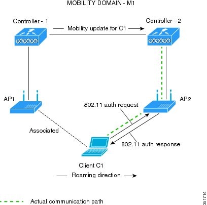
802.11r, which is the IEEE standard for fast roaming, introduces a new concept of roaming where the initial handshake with the new AP is done even before the client roams to the target AP, which is called Fast Transition (FT). The initial handshake allows the client and APs to do the Pairwise Transient Key (PTK) calculation in advance. These PTK keys are applied to the client and AP after the client does the reassociation request or response exchange with new target AP.
802.11r provides two methods of roaming:
-
Over-the-Air
-
Over-the-DS (Distribution System)
The FT key hierarchy is designed to allow clients to make fast BSS transitions between APs without requiring reauthentication at every AP. WLAN configuration contains a new Authenticated Key Management (AKM) type called FT (Fast Transition).
From Release 8.0, you can create an 802.11r WLAN that is also an WPAv2 WLAN. In earlier releases, you had to create separate WLANs for 802.11r and for normal security. Non-802.11r clients can now join 802.11r-enabled WLANs as the 802.11r WLANs can accept non-802.11r associations. If clients do not support mixed mode or 802.11r join, they can join non-802.11r WLANS. When you configure FT PSK and later define PSK, clients that can join only PSK can now join the WLAN in mixed mode.
How a Client Roams
For a client to move from its current AP to a target AP using the FT protocols, the message exchanges are performed using one of the following two methods:
-
Over-the-Air—The client communicates directly with the target AP using IEEE 802.11 authentication with the FT authentication algorithm.
-
Over-the-DS—The client communicates with the target AP through the current AP. The communication between the client and the target AP is carried in FT action frames between the client and the current AP and is then sent through the controller.

This section contains the following subsections:
Restrictions for 802.11r Fast Transition
-
This feature is not supported on mesh access points.
-
In 8.1 and earlier releases, this feature is not supported on access points in FlexConnect mode. In Release 8.2, this restriction is removed.
-
For APs in FlexConnect mode:
-
802.11r Fast Transition is supported in central and locally switched WLANs.
-
This feature is not supported for the WLANs enabled for local authentication.
-
802.11r client association is not supported on access points in standalone mode.
-
802.11r fast roaming is not supported on access points in standalone mode.
-
802.11r fast roaming between local authentication and central authentication WLAN is not supported.
-
802.11r fast roaming works only if the APs are in the same FlexConnect group.
-
-
802.11r fast roaming is not supported if the client uses Over-the-DS preauthentication in standalone mode.
-
EAP LEAP method is not supported. WAN link latency prevents association time to a maximum of 2 seconds.
-
The service from standalone AP to client is only supported until the session timer expires.
-
TSpec is not supported for 802.11r fast roaming. Therefore, RIC IE handling is not supported.
-
If WAN link latency exists, fast roaming is also delayed. Voice or data maximum latency should be verified. The Cisco WLC handles 802.11r Fast Transition authentication request during roaming for both Over-the-Air and Over-the-DS methods.
-
This feature is supported on open and WPA2 configured WLANs.
-
It is not possible to enable WPA1 encryption along with Fast Transition on a WLAN using the controller GUI. The workaround is to configure it using the controller CLI. For more information, see https://bst.cloudapps.cisco.com/bugsearch/bug/CSCvp05137.
-
Legacy clients cannot associate with a WLAN that has 802.11r enabled if the driver of the supplicant that is responsible for parsing the Robust Security Network Information Exchange (RSN IE) is old and not aware of the additional AKM suites in the IE. Due to this limitation, clients cannot send association requests to WLANs. These clients, however, can still associate with non-802.11r WLANs. Clients that are 802.11r capable can associate as 802.11i clients on WLANs that have both 802.11i and 802.11r Authentication Key Management Suites enabled.
The workaround is to enable or upgrade the driver of the legacy clients to work with the new 802.11r AKMs, after which the legacy clients can successfully associate with 802.11r enabled WLANs.
Another workaround is to have two SSIDs with the same name but with different security settings (FT and non-FT).
-
Fast Transition resource request protocol is not supported because clients do not support this protocol. Also, the resource request protocol is an optional protocol.
-
To avoid any Denial of Service (DoS) attack, each Cisco WLC allows a maximum of three Fast Transition handshakes with different APs.
-
Non-802.11r capable devices will not be able to associate with FT-enabled WLAN.
-
802.11r FT + PMF is not recommended.
-
802.11r FT Over-the-Air roaming is recommended for FlexConnect deployments.
-
In a default FlexGroup scenario, fast roaming is not supported.
Configuring 802.11r Fast Transition (GUI)
Procedure
| Step 1 |
Choose WLANs to open the WLANs window. |
||
| Step 2 |
Click a WLAN ID to open the WLANs > Edit window. |
||
| Step 3 |
Choose Security > Layer 2 tab. |
||
| Step 4 |
From the Layer 2 Security drop-down list, choose WPA+WPA2. The Authentication Key Management parameters for Fast Transition are displayed. |
||
| Step 5 |
From the Fast Transition drop-down list, choose Fast Transition on the WLAN. |
||
| Step 6 |
Check or uncheck the Over the DS check box to enable or disable Fast Transition over a distributed system. This option is available only if you enable Fast Transition or if Fast Transition is adaptive. To use 802.11r Fast Transition, Over-the-Air and Over-the-DS must be disabled. |
||
| Step 7 |
In the Reassociation Timeout field, enter the number of seconds after which the reassociation attempt of a client to an AP should time out. The valid range is 1 to 100 seconds.
|
||
| Step 8 |
Under Authentication Key Management, choose FT 802.1X or FT PSK. Check or uncheck the corresponding check boxes to enable or disable the keys. If you check the FT PSK check box, from the PSK Format drop-down list, choose ASCII or Hex and enter the key value.
|
||
| Step 9 |
From the WPA gtk-randomize State drop-down list, choose Enable or Disable to configure the Wi-Fi Protected Access (WPA) group temporal key (GTK) randomize state. |
||
| Step 10 |
Click Apply to save your settings. |
Configuring 802.11r Fast Transition (CLI)
802.11r-enabled WLAN provides faster roaming for wireless client devices. However, if 802.11r is enabled on a WLAN and advertises fast transition (FT) and non-FT AKMs in Beacon and Probe RSN IE, some of the devices with bad implementation may not recognise FT/WPA2 authentication key-management (AKM) in RSN IE and fails to join. As a result, customers cannot enable 802.11r on the SSID.
To overcome this, Cisco Wireless infrastructure introduces adaptive 802.11r Feature. When FT mode is set to adaptive, WLAN advertises 802.11r Mobility Domain ID on an 802.11i-enabled WLAN. Apple iOS10 client devices identifies the presence of MDIE on a 80211i/WPA2 WLAN and does a proprietary handshake to establish 802.11r association. Once the client completes successful 802.11r association, it will be able to do FT roaming as in a normal 802.11r enabled WLAN.
The FT adaptive is applicable only to selected Apple iOS10 devices. All other clients will continue to have 802.11i association on the WLAN.
Procedure
| Step 1 |
To enable or disable 802.11r fast transition parameters, use the config wlan security ft { adaptive | enable | disable} wlan-id command. Fast Transition adaptive option is enabled by default when you create a new WLAN, from Cisco Wireless Controller (WLC), Release 8.3, onwards. However, the existing WLANs will retain its current configuration when Cisco WLC upgrades to Release 8.3 from an earlier release. Enable Fast SSID feature for allowing client devices a smother switching smoother switching from one WLAN to another. . |
||
| Step 2 |
To enable or disable 802.11r fast transition parameters over a distributed system, use the config wlan security ft over-the-ds { enable | disable} wlan-id command. |
||
| Step 3 |
To enable or disable the authentication key management for fast transition using preshared keys (PSK), use the config wlan security wpa akm ft psk { enable | disable} wlan-id command. By default, the authentication key management using PSK is disabled. |
||
| Step 4 |
To enable or disable authentication key management for adaptive using PSK, use the config wlan security wpa akm psk { enable | disable} wlan-id command. |
||
| Step 5 |
To enable or disable authentication key management for fast transition using 802.1X, use the config wlan security wpa akm ft-802.1X { enable | disable} wlan-id command. By default, authentication key management using 802.1X is enabled. |
||
| Step 6 |
To enable or disable authentication key management for adaptive using 802.1x, use the config wlan security wpa akm 802.1x { enable | disable} wlan-id command.
|
||
| Step 7 |
To enable or disable 802.11r fast transition reassociation timeout, use the config wlan security ft reassociation-timeout timeout-in-seconds wlan-id command. The valid range is 1 to 100 seconds. The default value of reassociation timeout is 20 seconds. |
||
| Step 8 |
To view the fast transition configuration on a WLAN, use the show wlan wlan-id command. |
||
| Step 9 |
To view the fast transition configuration on a client, use the show client detail client-mac command.
|
||
| Step 10 |
To enable or disable debugging of fast transition events, use the debug ft events { enable | disable} command. |
What to do next
-
The tech support command output and xml config will not display fast transition information, when it is disabled.
-
The tech support command output and xml config will display Adaptive 802.11r information, when it is enabled.
-
To display a comprehensive view of the current Cisco WLC configuration, use the show run-config all command.
-
The fast transition adaptive mode is not supported on Releases prior to Release 8.3, the fast transition adaptive WLANs default to fast transition disable when Cisco WLC is downgraded from Release 8.3 to a previous release, and the fast transition adaptive configuration is invalidated.
Troubleshooting 802.11r BSS Fast Transition
| Symptom | Resolution |
|---|---|
| Non-802.11r legacy clients are no longer connecting. | Check if the WLAN has FT enabled. If so, non-FT WLAN will need to be created. |
| When configuring WLAN, the FT setup options are not shown. | Check if WPA2 is being used (802.1x / PSK). FT is supported only on WPA2 and OPEN SSIDs. |
| 802.11r clients appear to reauthenticate when they do a Layer 2 roam to a new controller. | Check if the reassociation timeout has been lowered from the default of 20 by navigating to WLANs > WLAN Name > Security > Layer 2 on the controller GUI. |
Sticky Key Caching
The controller supports sticky key caching (SKC). With sticky key caching, the client receives and stores a different PMKID for every AP it associates with. The APs also maintain a database of the PMKID issued to the client.
In SKC, the client stores each Pairwise Master Key ID (PMKID) against a Pairwise Master Key Security Association (PMKSA). When a client finds an AP for which it has the PMKSA, it sends the PMKID in the association request to the AP. If the PMKSA is alive in the AP, the AP provides support for fast roaming. In SKC, full authentication is done on each new AP to which the client associates and the client must keep the PMKSA associated with all APs. For SKC, PMKSA is a per AP cache that the client stores and PMKSA is precalculated based on the BSSID of the new AP.
This section contains the following subsections:
Restrictions for Sticky Key Caching
-
The controller supports SKC for up to eight APs per client. If a client roams to more than 8 APs per session, the old APs are removed to store the newly cached entries when the client roams. We recommend that you do not use SKC for large scale deployments.
-
SKC works only on WPA2-enabled WLANs.
-
SKC does not work across controllers in a mobility group.
-
SKC works only on local mode APs.
Configuring Sticky Key Caching (CLI)
Procedure
| Step 1 |
Disable the WLAN by entering this command: config wlan disable wlan_id |
||
| Step 2 |
Enable sticky key caching by entering this command: config wlan security wpa wpa2 cache sticky enable wlan_id By default, SKC is disabled and opportunistic key caching (OKC) is enabled.
You can check if SKC is enabled by entering this command: show wlan wlan_id Information similar to the following appears: |
||
| Step 3 |
Enable the WLAN by entering this command: config wlan enable wlan_id |
||
| Step 4 |
Save your settings by entering this command: save config |
WLAN for Static WEP
You can configure up to four WLANs to support static WEP keys. Follow these guidelines when configuring a WLAN for static WEP:
-
When you configure static WEP as the Layer 2 security policy, no other security policies can be specified. That is, you cannot configure web authentication. However, when you configure static WEP as the Layer 2 security policy, you can configure web authentication.
Restrictions for Configuring Static WEP
-
The controller software supports CCX versions 1 through 5. CCX support is enabled automatically for every WLAN on the controller and cannot be disabled. The controller stores the CCX version of the client in its client database and uses it to limit client functionality. Clients must support CCXv4 or v5 in order to use CCKM. For more information about CCX, see the Configuring Cisco Client Extensions section.
-
In a unified architecture where multiple VLAN clients are supported for a WGB, you also need to configure encryption cipher suite and WEP keys globally, when the WEP encryption is enabled on the WGB. Otherwise, multicast traffic for wired VLAN clients fail.
WPA1 and WPA2
Wi-Fi Protected Access (WPA or WPA1) and WPA2 are standards-based security solutions from the Wi-Fi Alliance that provide data protection and access control for wireless LAN systems. WPA1 is compatible with the IEEE 802.11i standard but was implemented prior to the standard’s ratification; WPA2 is the Wi-Fi Alliance's implementation of the ratified IEEE 802.11i standard.
By default, WPA1 uses Temporal Key Integrity Protocol (TKIP) and message integrity check (MIC) for data protection while WPA2 uses the stronger Advanced Encryption Standard encryption algorithm using Counter Mode with Cipher Block Chaining Message Authentication Code Protocol (AES-CCMP). Both WPA1 and WPA2 use 802.1X for authenticated key management by default. However, these options are also available:
-
802.1X—The standard for wireless LAN security, as defined by IEEE, is called 802.1X for 802.11, or simply 802.1X. An access point that supports 802.1X acts as the interface between a wireless client and an authentication server, such as a RADIUS server, to which the access point communicates over the wired network. If 802.1X is selected, only 802.1X clients are supported.
-
PSK—When you choose PSK (also known as WPA preshared key or WPA passphrase), you need to configure a preshared key (or a passphrase). This key is used as the pairwise master key (PMK) between the clients and the authentication server.
-
CCKM—Cisco Centralized Key Management (CCKM) uses a fast rekeying technique that enables clients to roam from one access point to another without going through the controller, typically in under 150 milliseconds (ms). CCKM reduces the time required by the client to mutually authenticate with the new access point and derive a new session key during reassociation. CCKM fast secure roaming ensures that there is no perceptible delay in time-sensitive applications such as wireless Voice over IP (VoIP), enterprise resource planning (ERP), or Citrix-based solutions. CCKM is a CCXv4-compliant feature. If CCKM is selected, only CCKM clients are supported.
When CCKM is enabled, the behavior of access points differs from the controller's for fast roaming in the following ways:
-
If an association request sent by a client has CCKM enabled in a Robust Secure Network Information Element (RSN IE) but CCKM IE is not encoded and only PMKID is encoded in RSN IE, then the controller does not do a full authentication. Instead, the controller validates the PMKID and does a four-way handshake.
-
If an association request sent by a client has CCKM enabled in RSN IE but CCKM IE is not encoded and only PMKID is encoded in RSN IE, then AP does a full authentication. The access point does not use PMKID sent with the association request when CCKM is enabled in RSN IE.
-
-
802.1X+CCKM—During normal operation, 802.1X-enabled clients mutually authenticate with a new access point by performing a complete 802.1X authentication, including communication with the main RADIUS server. However, when you configure your WLAN for 802.1X and CCKM fast secure roaming, CCKM-enabled clients securely roam from one access point to another without the need to reauthenticate to the RADIUS server. 802.1X+CCKM is considered optional CCKM because both CCKM and non-CCKM clients are supported when this option is selected.
On a single WLAN, you can allow WPA1, WPA2, and 802.1X/PSK/CCKM/802.1X+CCKM clients to join. All of the access points on such a WLAN advertise WPA1, WPA2, and 802.1X/PSK/CCKM/ 802.1X+CCKM information elements in their beacons and probe responses. When you enable WPA1 and/or WPA2, you can also enable one or two ciphers, or cryptographic algorithms, designed to protect data traffic. Specifically, you can enable AES and/or TKIP data encryption for WPA1 and/or WPA2. TKIP is the default value for WPA1, and AES is the default value for WPA2.
This section contains the following subsections:
Configuring WPA1+WPA2 (GUI)
Procedure
| Step 1 |
Choose WLANs to open the WLANs page. |
||
| Step 2 |
Click the ID number of the desired WLAN to open the WLANs > Edit page. |
||
| Step 3 |
Choose the Security and Layer 2 tabs to open the WLANs > Edit (Security > Layer 2) page. |
||
| Step 4 |
Choose WPA+WPA2 from the Layer 2 Security drop-down list. |
||
| Step 5 |
Under WPA+WPA2 Parameters, select the WPA Policy check box to enable WPA1, select the WPA2 Policy check box to enable WPA2, or select both check boxes to enable both WPA1 and WPA2.
|
||
| Step 6 |
Select the WPA2 Policy-AES check box to enable AES data encryption .
|
||
| Step 7 |
Choose one of the following key management methods from the Auth Key Mgmt drop-down list: 802.1X, CCKM, PSK, or 802.1X+CCKM. |
||
| Step 8 |
If you chose PSK in Step 7, choose ASCII or HEX from the PSK Format drop-down list and then enter a preshared key in the blank text box. WPA preshared keys must contain 8 to 63 ASCII text characters or 64 hexadecimal characters.
|
||
| Step 9 |
Click Apply to commit your changes. |
||
| Step 10 |
Click Save Configuration to save your changes. |
Configuring WPA1+WPA2 (CLI)
Procedure
| Step 1 |
Disable the WLAN by entering this command: config wlan disable wlan_id |
||||
| Step 2 |
Enable or disable WPA for the WLAN by entering this command: config wlan security wpa {enable | disable} wlan_id |
||||
| Step 3 |
Enable or disable WPA1 for the WLAN by entering this command: config wlan security wpa wpa1 {enable | disable} wlan_id |
||||
| Step 4 |
Enable or disable WPA2 for the WLAN by entering this command: config wlan security wpa wpa2 {enable | disable} wlan_id |
||||
| Step 5 |
Enable or disable AES or TKIP data encryption for WPA1 or WPA2 by entering one of these commands:
The default values are TKIP for WPA1 and AES for WPA2.
When you have VLAN configuration on WGB, you need to configure the encryption cipher mode and keys for a particular VLAN, for example, encryption vlan 80 mode ciphers tkip . Then, you need configure the encryption cipher mode globally on the multicast interface by entering the following command: encryption mode ciphers tkip . |
||||
| Step 6 |
Enable or disable 802.1X, PSK, or CCKM authenticated key management by entering this command: config wlan security wpa akm {802.1X | psk | cckm} {enable | disable} wlan_id The default value is 802.1X. |
||||
| Step 7 |
If you enabled PSK in Step 6, enter this command to specify a preshared key: config wlan security wpa akm psk set-key {ascii | hex} psk-key wlan_id WPA preshared keys must contain 8 to 63 ASCII text characters or 64 hexadecimal characters. |
||||
| Step 8 |
Enable or disable authentication key management suite for fast transition by entering this command: config wlan security wpa akm ft {802.1X | psk} {enable | disable} wlan_id
|
||||
| Step 9 |
Enable or disable randomization of group temporal keys (GTK) between AP and clients by entering this command: config wlan security wpa gtk-random {enable | disable} wlan_id |
||||
| Step 10 |
If you enabled WPA2 with 802.1X authenticated key management or WPA1 or WPA2 with CCKM authenticated key management, the PMK cache lifetime timer is used to trigger reauthentication with the client when necessary. The timer is based on the timeout value received from the AAA server or the WLAN session timeout setting. To see the amount of time remaining before the timer expires, enter this command: show pmk-cache all If you enabled WPA2 with 802.1X authenticated key management, the controller supports both opportunistic PMKID caching and sticky (or non-opportunistic) PMKID caching. In sticky PMKID caching (SKC), the client stores multiple PMKIDs, a different PMKID for every AP it associates with. Opportunistic PMKID caching (OKC) stores only one PMKID per client. By default, the controller supports OKC. |
||||
| Step 11 |
Enable the WLAN by entering this command: config wlan enable wlan_id |
||||
| Step 12 |
Save your settings by entering this command: save config |
Identity PSK
This feature is designed to provide a simple and secured way for the growing number of devices to connect to the network. Some devices such as Internet of Things (IoT) clients may not support the 802.1x security protocol. These devices can connect to the network using the PSK authentication mechanism.
If all the clients are using the same key and if the key is shared with unauthorized users, then it leads to security breach.
The IPSK feature enables the administrator to configure WPA-PSK protocol-based unique pre-shared keys in the same SSID. This pre-shared key can be issued to an individual or group of users for their devices to connect to the network easily and safely. This also helps in identifying and managing a set of devices without affecting the other pre-shared key devices connected to the network. These keys can be configured with rules to authenticate and provide the appropriate level of access in the network.
Here, the AAA RADIUS server key is used to authenticate the client.
For documentation on Cisco ISE configuration, see Cisco ISE 2.2 Administrator Guide.
This section contains the following subsections:
Prerequisites for Identity PSK
The RADIUS server must be configured to return the following Cisco AV pairs in its response to the MAC-filtering authentication request:
-
psk-mode=ascii
-
psk=cisco123
Key length must be between 8 and 63 characters for ASCII and 64 characters for HEX. If the key configured on the RADIUS server does not meet the length requirement, the client can be authenticated with PSK configured on the WLAN.
Configuring Identity PSK (GUI)
Procedure
| Step 1 |
Choose WLAN to open the WLAN page. |
| Step 2 |
Create a new WLAN or click an existing WLAN. |
| Step 3 |
Select the Status Enabled check box. |
| Step 4 |
Choose tab. |
| Step 5 |
Choose WPA+WPA2 from the Layer 2 Security drop-down list. |
| Step 6 |
Select the MAC Filtering check box. |
| Step 7 |
Select PSK Enable check box under Authentication Key Management. |
| Step 8 |
Choose tab. |
| Step 9 |
Select the Authentication Servers Enabled check box. |
| Step 10 |
Select the Server IP address and port number from the drop-down list. If the RADIUS server is not configured, the RADIUS server is selected from the global list. |
| Step 11 |
Choose Advanced tab. |
| Step 12 |
Select the Allow AAA Override Enabled check box to enable AAA override. The default value is disabled. |
| Step 13 |
Click Apply. |
Configuring Identity PSK (CLI)
Procedure
Web Redirect with 802.1X Authentication
You can configure a WLAN to redirect a user to a particular web page after 802.1X authentication has completed successfully. You can configure the web redirect to give the user partial or full access to the network.
This section contains the following subsections:
Conditional Web Redirect
If you enable conditional web redirect, the user can be conditionally redirected to a particular web page after 802.1X authentication has completed successfully. You can specify the redirect page and the conditions under which the redirect occurs on your RADIUS server. Conditions might include the user’s password reaching expiration or the user needing to pay his or her bill for continued usage.
If the RADIUS server returns the Cisco AV-pair “url-redirect,” then the user is redirected to the specified URL upon opening a browser. If the server also returns the Cisco AV-pair “url-redirect-acl,” the specified access control list (ACL) is installed as a preauthentication ACL for this client. The client is not considered fully authorized at this point and can only pass traffic allowed by the preauthentication ACL.
After the client completes a particular operation at the specified URL (for example, changing a password or paying a bill), the client must reauthenticate. When the RADIUS server does not return a “url-redirect,” the client is considered fully authorized and allowed to pass traffic.
Note |
The conditional web redirect feature is available only for WLANs that are configured for 802.1X or WPA+WPA2 Layer 2 security. |
After you configure the RADIUS server, you can then configure the conditional web redirect on the controller using either the controller GUI or CLI.
Splash Page Web Redirect
If you enable splash page web redirect, the user is redirected to a particular web page after 802.1X authentication has completed successfully. After the redirect, the user has full access to the network. You can specify the redirect page on your RADIUS server and the corresponding ACL to allow access to this server in "url-redirect-acl". If the RADIUS server returns the Cisco AV-pair “url-redirect,” then the user is redirected to the specified URL upon opening a browser. The client is considered fully authorized at this point and is allowed to pass traffic, even if the RADIUS server does not return a “url-redirect.”
Note |
The splash page web redirect feature is available only for WLANs that are configured for 802.1X or WPA+WPA2 Layer 2 security with 802.1x key management. Preshared key management is not supported with any Layer 2 security method. |
Suppose there are backend applications running on the wireless clients and they use HTTP or HTTPS port for their communication. If the applications start communicating before the actual web page is opened, the redirect functionality does not work with web passthrough.
After you configure the RADIUS server, you can then configure the splash page web redirect on the controller using either the controller GUI or CLI.
Configuring the RADIUS Server (GUI)
Note |
These instructions are specific to the CiscoSecure ACS; however, they should be similar to those for other RADIUS servers. |
Procedure
| Step 1 |
From the CiscoSecure ACS main menu, choose Group Setup. |
| Step 2 |
Click Edit Settings. |
| Step 3 |
From the Jump To drop-down list, choose RADIUS (Cisco IOS/PIX 6.0). |
| Step 4 |
Select the [009\001] cisco-av-pair check box. |
| Step 5 |
Enter the following Cisco AV-pairs in the [009\001] cisco-av-pair edit box to specify the URL to which the user is redirected and, if configuring conditional web redirect, the conditions under which the redirect takes place, respectively: url-redirect=http://url url-redirect-acl=acl_name |
Configuring Web Redirect
Configuring Web Redirect (GUI)
Procedure
| Step 1 |
Choose WLANs to open the WLANs page. |
| Step 2 |
Click the ID number of the desired WLAN. The WLANs > Edit page appears. |
| Step 3 |
Choose the Security and Layer 2 tabs to open the WLANs > Edit (Security > Layer 2) page. |
| Step 4 |
From the Layer 2 Security drop-down list, choose 802.1X or WPA+WPA2. |
| Step 5 |
Set any additional parameters for 802.1X or WPA+WPA2. |
| Step 6 |
Choose the Layer 3 tab to open the WLANs > Edit (Security > Layer 3) page. |
| Step 7 |
From the Layer 3 Security drop-down list, choose None. |
| Step 8 |
Check the Web Policy check box. |
| Step 9 |
Choose one of the following options to enable conditional or splash page web redirect: Conditional Web Redirect or Splash Page Web Redirect. The default value is disabled for both parameters. |
| Step 10 |
If the user is to be redirected to a site external to the controller, choose the ACL that was configured on your RADIUS server from the Preauthentication ACL drop-down list. |
| Step 11 |
Click Apply to commit your changes. |
| Step 12 |
Click Save Configuration to save your changes. |
Configuring Web Redirect (CLI)
Procedure
| Step 1 |
Enable or disable conditional web redirect by entering this command: config wlan security cond-web-redir {enable | disable} wlan_id |
| Step 2 |
Enable or disable splash page web redirect by entering this command: config wlan security splash-page-web-redir {enable | disable} wlan_id |
| Step 3 |
Save your settings by entering this command: save config |
| Step 4 |
See the status of the web redirect features for a particular WLAN by entering this command: show wlan wlan_id Information similar to the following appears: |
 Feedback