Cisco Wireless Controller Configuration Guide, Release 8.3
Bias-Free Language
The documentation set for this product strives to use bias-free language. For the purposes of this documentation set, bias-free is defined as language that does not imply discrimination based on age, disability, gender, racial identity, ethnic identity, sexual orientation, socioeconomic status, and intersectionality. Exceptions may be present in the documentation due to language that is hardcoded in the user interfaces of the product software, language used based on RFP documentation, or language that is used by a referenced third-party product. Learn more about how Cisco is using Inclusive Language.
- Updated:
- July 28, 2016
Chapter: Ports and Interfaces
- Ports
- Link Aggregation
- Information About Link Aggregation
- Restrictions on Link Aggregation
- Configuring Link Aggregation (GUI)
- Configuring Link Aggregation (CLI)
- Verifying Link Aggregation Settings (CLI)
- Configuring Neighbor Devices to Support Link Aggregation
- Choosing Between Link Aggregation and Multiple AP-Manager Interfaces
- Interfaces
- Information About Interfaces
- Information About Dynamic AP Management
- Information About WLANs
- Management Interface
- Virtual Interface
- Service-Port Interfaces
- Information About Service-Port Interfaces
- Restrictions on Configuring Service-Port Interfaces
- Configuring Service-Port Interfaces Using IPv4 (GUI)
- Configuring Service-Port Interfaces Using IPv4 (CLI)
- Configuring Service-Port Interface Using IPv6 (GUI)
- Configuring Service-Port Interfaces Using IPv6 (CLI)
- Dynamic Interfaces
- AP-Manager Interface
- Interface Groups
- Information About Interface Groups
- Restrictions on Configuring Interface Groups
- Creating Interface Groups (GUI)
- Creating Interface Groups (CLI)
- Adding Interfaces to Interface Groups (GUI)
- Adding Interfaces to Interface Groups (CLI)
- Viewing VLANs in Interface Groups (CLI)
- Adding an Interface Group to a WLAN (GUI)
- Adding an Interface Group to a WLAN (CLI)
Ports and
Interfaces
Ports
Information About Ports
A port is a physical entity that is used for connections on the Cisco WLC platform. Cisco WLCs have two types of ports:
-
Distribution system ports
-
Service port
For more information about Cisco Unified Wireless Network Protocol and Port Matrix, see http://www.cisco.com/c/en/us/support/docs/wireless/5500-series-wireless-controllers/113344-cuwn-ppm.html.
Information About Distribution System Ports
A distribution system port connects the controller to a neighbor switch and serves as the data path between these two devices.
Restrictions for Configuring Distribution System Ports
-
Cisco 5508 WLCs have eight Gigabit Ethernet distribution system ports, through which the Controller can manage multiple access points. The 5508-12, 5508-25, 5508-50, 5508-100, and 5508-250 models allow a total of 12, 25, 50, 100, or 250 access points to join the controller. Cisco 5508 WLCs have no restrictions on the number of access points per port. However, we recommend using link aggregation (LAG) or configuring dynamic AP-manager interfaces on each Gigabit Ethernet port to automatically balance the load. If more than 100 access points are connected to the Cisco 5508 WLC, ensure that more than one Gigabit Ethernet interface is connected to the upstream switch.

Note
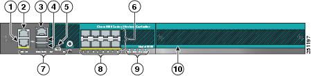
The Gigabit Ethernet ports on the Cisco 5508 WLCs accept these SX/LC/T small form-factor plug-in (SFP) modules: - -
1000BASE-SX SFP modules, which provide a 1000-Mbps wired connection to a network through an 850nM (SX) fiber-optic link using an LC physical connector
-
1000BASE-LX SFP modules, which provide a 1000-Mbps wired connection to a network through a 1300nM (LX/LH) fiber-optic link using an LC physical connector
-
1000BASE-T SFP modules, which provide a 1000-Mbps wired connection to a network through a copper link using an RJ-45 physical connector
-
- GLC-SX-MM, a 1000BASE-SX connector should be in auto-negotiation mode to function as desired because all SFP modules using LC physical connecters must ideally be in auto-negotiation mode on Cisco 5508 Series Controllers to function properly. However, when Cisco ASR is connected using the fiber port, GLC-SX-MM does not come up between Cisco ASR and Cisco 5508 as Cisco ASR requires the connector to be in fixed mode to function properly.
-
Each distribution system port is, by default, an 802.1Q VLAN trunk port. The VLAN trunking characteristics of the port are not configurable.
Note
Some controllers support link aggregation (LAG), which bundles all of the controller’s distribution system ports into a single 802.3ad port channel. Cisco 5508 WLCs support LAG, and LAG is enabled automatically on the controllers within the Cisco WiSM2.
-
Cisco WLC configuration in access mode is not supported. We recommend that you configure Cisco WLC in trunk mode when you configure Cisco WLC ports on a switch.
-
In Cisco Flex 7510 and 8510 Controllers:
-
If a port is unresponsive after a soaking period of 5 seconds, all the interfaces for which the port is the primary and the active port, fail over to the backup port, if a backup is configured and is operational. Similarly, if the unresponsive port is the backup port, then all the interfaces fail over to the primary port if it is operational.
-
After the unresponsive port is restored, there is a soaking period of 60 seconds after which if the port is still operational, then all the interfaces fall back to this port, which was the primary port. If the port was the backup port, then no change is done.
-
-
You must ensure that you configure the port before you connect a switch or distribution system in the Cisco 2504 WLC.
-
If an IPv6 packet is destined to controller management IPv6 address and the client VLAN is different from the controller management VLAN, then the IPv6 packet is switched out of the WLC box. If the same IPv6 packet comes as a network packet to the WLC, management access is not denied.
Information About Service Port
Cisco 5500 Series Controllers also have a 10/100/1000 copper Ethernet service port. The service port is controlled by the service-port interface and is reserved for out-of-band management of the controller and system recovery and maintenance in the event of a network failure. It is also the only port that is active when the controller is in boot mode. The service port is not capable of carrying 802.1Q tags, so it must be connected to an access port on the neighbor switch. Use of the service port is optional.
The service port of the Cisco Flex 7510 and 8510 WLC models is a one Gigabit Ethernet port. To verify the speed of service port, you must connect the service port to a Gigabit Ethernet port on the switch.
Note | The service port is not auto-sensing. You must use the correct straight-through or crossover Ethernet cable to communicate with the service port. |
 Caution | Do not configure wired clients in the same VLAN or subnet of the service port of the controller on the network. If you configure wired clients on the same subnet or VLAN as the service port, it is not possible to access the management interface of the controller. |
For information about service ports in the applicable Cisco WLCs, see the respecitve Cisco WLC documentation:
Configuring Ports (GUI)
The controller’s ports are configured with factory-default settings designed to make the controllers’ ports operational without additional configuration. However, you can view the status of the controller’s ports and edit their configuration parameters at any time.
| Step 1 | Choose
to open the Ports page.
This page shows the current configuration for each of the controller’s ports. If you want to change the settings of any port, click the number for that specific port. The Port > Configure page appears.
The following show the current status of the port:
The following is a list of the port’s configurable parameters.
| ||||||||
| Step 2 | Click Apply. | ||||||||
| Step 3 | Click Save Configuration. | ||||||||
| Step 4 | Click Back to return to the Ports page and review your changes. | ||||||||
| Step 5 | Repeat this procedure for each additional port that you want to configure. |
Link Aggregation
Information About Link Aggregation
Link aggregation (LAG) is a partial implementation of the 802.3ad port aggregation standard. It bundles all of the controller’s distribution system ports into a single 802.3ad port channel. This reduces the number of IP addresses required to configure the ports on your controller. When LAG is enabled, the system dynamically manages port redundancy and load balances access points transparently to the user.
LAG simplifies controller configuration because you no longer require to configure primary and secondary ports for each interface. If any of the controller ports fail, traffic is automatically migrated to one of the other ports. As long as at least one controller port is functioning, the system continues to operate, access points remain connected to the network, and wireless clients continue to send and receive data.
Cisco WLC does not send CDP advertisements on a LAG interface.
Note | LAG is supported across switches. |
Link Aggregation for Cisco Aironet 1850 Series Access Points
Cisco Aironet 1850 Series 802.11ac Wave 2 Access Points have two Gigabit Ethernet interfaces, the PoE port and the AUX port, which, by using Link Aggregation, can together accommodate the greater than 1 Gbps of throughput expected with Wave 2.
Note | Only Link Aggregation Control Protocol (LACP) is supported; Port Aggregation Protocol (PAgP) is not supported. |
LAG is supported on Cisco Aironet 1850 Series APs with the following switches:
Restrictions on Link Aggregation
-
You can bundle all eight ports on a Cisco 5508 Controller into a single link.
-
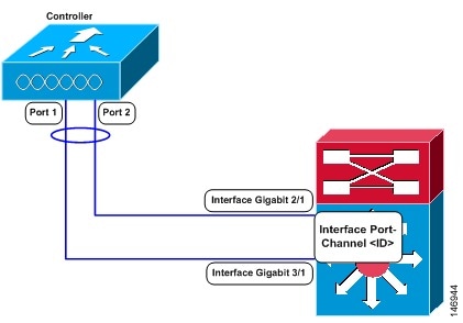
Terminating on two different modules within a single Catalyst 6500 series switch provides redundancy and ensures that connectivity between the switch and the controller is maintained when one module fails. The controller’s port 1 is connected to Gigabit interface 3/1, and the controller’s port 2 is connected to Gigabit interface 2/1 on the Catalyst 6500 series switch. Both switch ports are assigned to the same channel group.
-
LAG requires the EtherChannel to be configured for 'mode on' on both the controller and the Catalyst switch.
-
Once the EtherChannel is configured as on at both ends of the link, the Catalyst switch should not be configured for either Link Aggregation Control Protocol (LACP) or Cisco proprietary Port Aggregation Protocol (PAgP) but be set unconditionally to LAG. Because no channel negotiation is done between the controller and the switch, the controller does not answer to negotiation frames and the LAG is not formed if a dynamic form of LAG is set on the switch. Additionally, LACP and PAgP are not supported on the controller.
-
If the recommended load-balancing method cannot be configured on the Catalyst switch, then configure the LAG connection as a single member link or disable LAG on the controller.
Figure 2. Link Aggregation with the Catalyst 6500 Series Neighbor Switch
-
You cannot configure the controller’s ports into separate LAG groups. Only one LAG group is supported per controller. Therefore, you can connect a controller in LAG mode to only one neighbor device.
-
When you enable LAG or make any changes to the LAG configuration, you must immediately reboot the controller.
-
When you enable LAG, you can configure only one AP-manager interface because only one logical port is needed. LAG removes the requirement for supporting multiple AP-manager interfaces.
-
When you enable LAG, all dynamic AP-manager interfaces and untagged interfaces are deleted, and all WLANs are disabled and mapped to the management interface. Also, the management, static AP-manager, and VLAN-tagged dynamic interfaces are moved to the LAG port.
-
Multiple untagged interfaces to the same port are not allowed.
-
When you enable LAG, you cannot create interfaces with a primary port other than 29.
-
When you enable LAG, all ports participate in LAG by default. You must configure LAG for all of the connected ports in the neighbor switch.
-
When you enable LAG, if any single link goes down, traffic migrates to the other links.
-
When you enable LAG, only one functional physical port is needed for the controller to pass client traffic.
-
When you enable LAG, access points remain connected to the controller until you reboot the controller, which is needed to activate the LAG mode change, and data service for users continues uninterrupted.
-
When you enable LAG, you eliminate the need to configure primary and secondary ports for each interface.
-
When you enable LAG, the controller sends packets out on the same port on which it received them. If a CAPWAP packet from an access point enters the controller on physical port 1, the controller removes the CAPWAP wrapper, processes the packet, and forwards it to the network on physical port 1. This may not be the case if you disable LAG.
-
When you disable LAG, the management, static AP-manager, and dynamic interfaces are moved to port 1.
-
When you disable LAG, you must configure primary and secondary ports for all interfaces.
-
When you disable LAG, you must assign an AP-manager interface to each port on the controller. Otherwise, access points are unable to join.
-
Cisco 5508 WLC supports a single static link aggregation bundle.
-
LAG is typically configured using the Startup Wizard, but you can enable or disable it at any time through either the GUI or CLI.
-
When you enable LAG on Cisco 2504 WLC to which the direct-connect access point is associated, the direct connect access point is disconnected since LAG enabling is still in the transition state. You must reboot the controller immediately after enabling LAG.
-
In Cisco 8510 WLCs, when more than 1000 APs join the Cisco WLC, flapping occurs. To avoid this, we recommend that you do not add more than 1000 APs on a single Cisco Catalyst switch for CAPWAP IPv6.
Configuring Link Aggregation (GUI)
Configuring Link Aggregation (CLI)
Configuring Link Aggregation for Cisco 1850 Series APs (CLI)
Configure the Cisco Aironet 1850 Series AP link aggregation by entering this global configuration command: config ap lag-mode support {enable | disable}
Disabling global link aggregation for the APs will result in a reboot of all the lag enabled APs.
Configure link aggregation for a specific Cisco AP by entering this command: config ap lag-mode support {enable | disable} ap-name
Enabling or disabling link aggregation for the Cisco AP resets and reboots the specified Cisco AP.
Enable and configure Port Channel mode on switches connected to the Cisco AP. For optimal traffic load balancing on the LAG ports to the Cisco AP, ensure that the switch supports balancing based purely on the L4 source and destination ports.
Configuration Example:
interface Port-channel20
description 1852I lag
switchport access vlan 1107
switchport mode access

interface GigabitEthernet1/0/1
switchport access vlan 1107
switchport mode access
channel-group 20 mode active

interface GigabitEthernet1/0/2
switchport access vlan 1107
switchport mode access
channel-group 20 mode active
For more information about this step, see the Cisco Aironet 1850 Series Access Point Deployment Guide at http://www.cisco.com/c/en/us/td/docs/wireless/controller/technotes/8-1/1850_DG/b_Cisco_Aironet_Series_1850_Access_Point_Deployment_Guide.html.
After link aggregation is enabled on the Cisco AP, the Cisco WLC and the Cisco AP use multiple CAPWAP data tunnels to send and receive wireless client traffic.
View the link aggregation status by entering these commands:
Verifying Link Aggregation Settings (CLI)
To verify your LAG settings, enter this command:
Information similar to the following appears:
LAG Enabled
Configuring Neighbor Devices to Support Link Aggregation
The controller’s neighbor devices must also be properly configured to support LAG.
Each neighbor port to which the controller is connected should be configured as follows:
interface GigabitEthernet <interface id>
	switchport
	channel-group <id> mode on
	no shutdown
The port channel on the neighbor switch should be configured as follows:
interface port-channel <id>
	switchport
	switchport trunk encapsulation dot1q
	switchport trunk native vlan <native vlan id>
	switchport trunk allowed vlan <allowed vlans>
	switchport mode trunk
	no shutdown
Choosing Between Link Aggregation and Multiple AP-Manager Interfaces
Cisco WLCs have no restrictions on the number of access points per port, but we recommend that you use link aggregation (LAG) or multiple AP-manager interfaces on each Gigabit Ethernet port to automatically balance the load.
The following factors should help you decide which method to use if your Cisco WLC is set for Layer 3 operation:
With LAG, all of the Cisco WLC ports need to connect to the same neighbor switch. If the neighbor switch goes down, the Cisco WLC loses connectivity.
With multiple AP-manager interfaces, you can connect your ports to different neighbor devices. If one of the neighbor switches goes down, the Cisco WLC still has connectivity. However, using multiple AP-manager interfaces presents certain challenges when port redundancy is a concern.
Interfaces
Information About Interfaces
An interface is a logical entity on the controller. An interface has multiple parameters associated with it, including an IP address, default gateway (for the IP subnet), primary physical port, secondary physical port, VLAN identifier, and DHCP server.
These five types of interfaces are available on the controller. Four of these are static and are configured at setup time:
-
Management interface (static and configured at setup time; mandatory)
-
AP-manager interface (static and configured at setup time; mandatory)
Note
You are not required to configure an AP-manager interface on Cisco 5508 WLCs.
-
Virtual interface (static and configured at setup time; mandatory)
-
Service-port interface (static and configured at setup time; optional)
Note | Typically, you define the management, AP-manager, virtual, and service-port interface parameters using the Startup Wizard. However, you can display and configure interface parameters through either the GUI or CLI after the controller is running. |
When LAG is disabled, each interface is mapped to at least one primary port, and some interfaces (management and dynamic) can be mapped to an optional secondary (or backup) port. If the primary port for an interface fails, the interface automatically moves to the backup port. In addition, multiple interfaces can be mapped to a single controller port.
In Cisco Wireless LAN Controller 5508 Series, the controller marks packets greater than 1500 bytes as long. However, the packets are not dropped. The workaround to this is to configure the MTU on a switch to less than 1500 bytes.
Note | Interfaces that are quarantined are not displayed on the Controller > Interfaces page. For example, if there are 6 interfaces and one of them is quarantined, the quarantined interface is not displayed and the details of the other 5 interfaces are displayed on the GUI. You can get the total number of interfaces that is inclusive of quarantined interfaces through the count displayed on the top-right corner of the GUI. |
Restrictions on Configuring Interfaces
-
Each physical port on the wireless controller can have only one AP-manager configured with it. For the Cisco 5508 WLCs, the management interface with AP-management enabled cannot fail over to the backup port, which is primary for the AP-manager on the management or dynamic VLAN interface.
-
Cisco 5508 WLCs do not support fragmented pings on any interface.
-
When the port comes up in VMware ESXi with configuration for NIC teaming, the vWLC may lose connectivity. However, the Cisco vWLC resumes connectivity after a while.
-
IPv4 address needs to be configured on the interface prior to configuring the IPv6 address.
Information About Dynamic AP Management
A dynamic interface is created as a WLAN interface by default. However, any dynamic interface can be configured as an AP-manager interface, with one AP-manager interface allowed per physical port. A dynamic interface with the Dynamic AP Management option enabled is used as the tunnel source for packets from the controller to the access point and as the destination for CAPWAP packets from the access point to the controller. The dynamic interfaces for AP management must have a unique IP address and are usually configured on the same subnet as the management interface.
Note | If link aggregation (LAG) is enabled, there can be only one AP-manager interface. |
We recommend having a separate dynamic AP-manager interface per controller port.
Information About WLANs
A WLAN associates a service set identifier (SSID) to an interface or an interface group. It is configured with security, quality of service (QoS), radio policies, and other wireless network parameters. Up to 512 WLANs can be configured per controller.
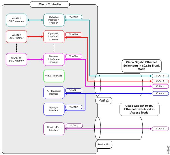
Each controller port connection is an 802.1Q trunk and should be configured as such on the neighbor switch. On Cisco switches, the native VLAN of an 802.1Q trunk is an untagged VLAN. If you configure an interface to use the native VLAN on a neighboring Cisco switch, make sure you configure the interface on the controller to be untagged.
Note | A zero value for the VLAN identifier (on the Controller > Interfaces page) means that the interface is untagged. |
The default (untagged) native VLAN on Cisco switches is VLAN 1. When controller interfaces are configured as tagged (meaning that the VLAN identifier is set to a nonzero value), the VLAN must be allowed on the 802.1Q trunk configuration on the neighbor switch and not be the native untagged VLAN.
We recommend that tagged VLANs be used on the controller. You should also allow only relevant VLANs on the neighbor switch’s 802.1Q trunk connections to controller ports. All other VLANs should be disallowed or pruned in the switch port trunk configuration. This practice is extremely important for optimal performance of the controller.
Note | We recommend that you assign one set of VLANs for WLANs and a different set of VLANs for management interfaces to ensure that controllers properly route VLAN traffic. |
Management Interface
Information About the Management Interface
The management interface is the default interface for in-band management of the controller and connectivity to enterprise services such as AAA servers. It is also used for communications between the controller and access points. The management interface has the only consistently “pingable” in-band interface IP address on the controller. You can access the GUI of the controller by entering the management interface IP address of the controller in the address field of your browser.
For CAPWAP, the controller requires one management interface to control all inter-controller communications and one AP-manager interface to control all controller-to-access point communications, regardless of the number of ports.
If the service port is in use, the management interface must be on a different supernet from the service-port interface.
Note | To prevent or block a wired or wireless client from accessing the management network on a controller (from the wireless client dynamic interface or VLAN), the network administrator must ensure that only authorized clients gain access to the management network through proper CPU ACLs, or use a firewall between the client dynamic interface and the management network. |
Caution | Do not map a guest WLAN to the management interface. If the EoIP tunnel breaks, the client could obtain an IP and be placed on the management subnet. |
Caution | Do not configure wired clients in the same VLAN or subnet of the service port of the controller on the network. If you configure wired clients on the same subnet or VLAN as the service port, it is not possible to access the management interface of the controller. |
Authentication Type for Management Interfaces
Example
- Configure TACACS+ server by entering these commands:
- Configure the server group name by entering these commands:
- Configure authentication and
authorization by entering these commands:
- aaa authentication login method-list group server-group
- aaa authorization exec
method-list
group
server-group
Note
These and all the other authentication and authorization parameters must be using the same database, be it RADIUS, TACACS+, or Local. For example, if command authorization has to be enabled, it also needs to be pointing to the same database.
-
Configure HTTP to use the above method lists:
Note |
|
Workaround
Configuring the Management Interface (GUI)
| Step 1 | Choose Controller > Interfaces to open the Interfaces page. | ||||||||||||||||
| Step 2 | Click the
management link.
The Interfaces > Edit page appears. | ||||||||||||||||
| Step 3 | Set the
management interface parameters:
| ||||||||||||||||
| Step 4 | Click Save Configuration. | ||||||||||||||||
| Step 5 | If you made any changes to the management or virtual interface, reboot the controller so that your changes take effect. |
Configuring the Management Interface (CLI)
| Step 1 | Enter the
show interface detailed management command to view
the current management interface settings.
| ||
| Step 2 | Enter the config wlan disable wlan-number command to disable each WLAN that uses the management interface for distribution system communication. | ||
| Step 3 | Enter these commands to
define the management interface:
| ||
| Step 4 | Enter these commands if you want to be able to deploy your Cisco WLC behind a router or other gateway device that is using one-to-one mapping network address translation (NAT):
NAT allows a device, such as a router, to act as an agent between the Internet (public) and a local network (private). In this case, it maps the Cisco WLC's intranet IP addresses to a corresponding external address. The controller’s dynamic AP-manager interface must be configured with the external NAT IP address so that the controller can send the correct IP address in the Discovery Response.
| ||
| Step 5 | Enter the save config command. | ||
| Step 6 | Enter the show interface detailed management command to verify that your changes have been saved. | ||
| Step 7 | If you made any changes to the management interface, enter the reset system command to reboot the controller in order for the changes to take effect. |
Virtual Interface
Information About the Virtual Interface
The virtual interface is used to support mobility management, Dynamic Host Configuration Protocol (DHCP) relay, and embedded Layer 3 security such as guest web authentication and VPN termination. It also maintains the DNS gateway host name used by Layer 3 security and mobility managers to verify the source of certificates when Layer 3 web authorization is enabled.
Specifically, the virtual interface plays these two primary roles:
Acts as the DHCP server placeholder for wireless clients that obtain their IP address from a DHCP server.
-
Serves as the redirect address for the web authentication login page.
The virtual interface IP address is used only in communications between the controller and wireless clients. It never appears as the source or destination address of a packet that goes out a distribution system port and onto the switched network. For the system to operate correctly, the virtual interface IP address must be set (it cannot be 0.0.0.0), and no other device on the network can have the same address as the virtual interface. Therefore, the virtual interface must be configured with an unassigned and unused gateway IP address. The virtual interface IP address is not pingable and should not exist in any routing table in your network. In addition, the virtual interface cannot be mapped to a physical port.
Restrictions
-
All controllers within a mobility group must be configured with the same virtual interface IP address. Otherwise, inter-controller roaming may appear to work, but the handoff does not complete, and the client loses connectivity for a period of time.
-
When Virtual Interface and Management Interface have the same IP address until the third octet, the Virtual Interface IP address will change to 0.0.0.0 after Cisco WLC is rebooted. Therefore, we recommend that you use /32 format of the IP address for the Virtual Interface.
Configuring Virtual Interfaces (GUI)
| Step 1 | Choose Controller > Interfaces to open the Interfaces page. |
| Step 2 | Click
Virtual.
The Interfaces > Edit page appears. |
| Step 3 | Enter the following parameters: |
| Step 4 | Click Save Configuration. |
| Step 5 | If you made any changes to the management or virtual interface, reboot the controller so that your changes take effect. |
Configuring Virtual Interfaces (CLI)
| Step 1 | Enter the show interface detailed virtual command to view the current virtual interface settings. |
| Step 2 | Enter the config wlan disable wlan-number command to disable each WLAN that uses the virtual interface for distribution system communication. |
| Step 3 | Enter these commands to define the virtual interface: |
| Step 4 | Enter the reset system command. At the confirmation prompt, enter Y to save your configuration changes to NVRAM. The controller reboots. |
| Step 5 | Enter the show interface detailed virtual command to verify that your changes have been saved. |
Service-Port Interfaces
Information About Service-Port Interfaces
The service-port interface controls communications through and is statically mapped by the system to the service port.
The service port can obtain an IPv4 address using DHCP, or it can be assigned a static IPv4 address, but a default gateway cannot be assigned to the service-port interface. Static IPv4 routes can be defined through the controller for remote network access to the service port.
If the service port is in use, the management interface must be on a different supernet from the service-port interface.
Similarly, the service port can be statically assigned an IPv6 address or select an IPv6 address using Stateless Address Auto-Configuration (SLAAC). The default gateway cannot be assigned to the service-port interface. Static IPv6 routes can be defined through the controller for remote network access to the service port.
Note | While IPv6 addressing is used along with stateless address auto-configuration, the controller does not perform the subnet verification; however, you must not connect the service-port in the same subnet as the other interfaces in the controller. |
Note | This is the only SLAAC interface on the controller, all other interfaces must be statically assigned (just like for IPv4). |
Note | User does not require IPv6 static routes to reach service port from the same network, but IPv6 routes requires to access service port from different network. The IPv6 static routes should be as same as IPv4. |
Restrictions on Configuring Service-Port Interfaces
Configuring Service-Port Interfaces Using IPv4 (GUI)
| Step 1 | Choose Controller > Interfaces to open the Interfaces page. | ||
| Step 2 | Click the service-port link to open the Interfaces > Edit page. | ||
| Step 3 | Enter the
Service-Port Interface parameters:
| ||
| Step 4 | Click Save Configuration to save your changes. | ||
| Step 5 | If you made any changes to the management or virtual interface, reboot the controller so that your changes take effect. |
Configuring Service-Port Interfaces Using IPv4 (CLI)
| Step 1 | To view the current
service-port interface settings, enter this command:
| ||
| Step 2 | Enter these commands to define the service-port interface: | ||
| Step 3 | The service port is used for out-of-band management of the controller. If the management workstation is in a remote subnet, you may need to add a IPv4 route on the controller in order to manage the controller from that remote workstation. To do so, enter this command: | ||
| Step 4 | To remove the IPv4 route on the controller, enter this command:
config route delete ip_address | ||
| Step 5 | Enter the save config command to save your changes. | ||
| Step 6 | Enter the show interface detailed service-port command to verify that your changes have been saved. |
Configuring Service-Port Interface Using IPv6 (GUI)
| Step 1 | Choose Controller > Interfaces to open the Interfaces page. | ||
| Step 2 | Click the service-port link to open the Interfaces > Edit page. | ||
| Step 3 | Enter the Service-Port Interface parameters:
| ||
| Step 4 | Click Save Configuration to save your changes. | ||
| Step 5 | If you made any changes to the management or virtual interface, reboot the controller so that your changes take effect. |
Configuring Service-Port Interfaces Using IPv6 (CLI)
| Step 1 | To view the current
service-port interface settings, enter this command:
| ||
| Step 2 | Enter these commands to
define the service-port interface:
| ||
| Step 3 | The service port
is used for out-of-band management of the controller. If the management
workstation is in a remote subnet, you may need to add a route on the
controller in order to manage the controller from that remote workstation. To
do so, enter this command:
config ipv6 route add network_ipv6_addr prefix-len ipv6_gw_addr | ||
| Step 4 | To remove the IPv6 route on the controller, enter this command:
config ipv6 route delete network _ipv6 addr | ||
| Step 5 | Enter the save config command to save your changes. | ||
| Step 6 | Enter the show interface detailed service-port command to verify that your changes have been saved. |
Dynamic Interfaces
Information About Dynamic Interface
Dynamic interfaces, also known as VLAN interfaces, are created by users and designed to be analogous to VLANs for wireless LAN clients. A controller can support up to 512 dynamic interfaces (VLANs). Each dynamic interface is individually configured and allows separate communication streams to exist on any or all of a controller’s distribution system ports. Each dynamic interface controls VLANs and other communications between controllers and all other network devices, and each acts as a DHCP relay for wireless clients associated to WLANs mapped to the interface. You can assign dynamic interfaces to distribution system ports, WLANs, the Layer 2 management interface, and the Layer 3 AP-manager interface, and you can map the dynamic interface to a backup port.
You can configure zero, one, or multiple dynamic interfaces on a distribution system port. However, all dynamic interfaces must be on a different VLAN or IP subnet from all other interfaces configured on the port. If the port is untagged, all dynamic interfaces must be on a different IP subnet from any other interface configured on the port.
For information about maximum number of VLANs supported on a Cisco WLC platform, see the respective Cisco WLC platform's datasheet.
Note | You must not configure a dynamic interface in the same network as that of Local Mobility Anchor (LMA). If you do so, the GRE tunnel between the controller and LMA does not come up. |
Prerequisites for Configuring Dynamic Interfaces
While configuring on the dynamic interface of the controller, you must ensure the following:
Restrictions on Configuring Dynamic Interfaces
The following restrictions apply for configuring the dynamic interfaces on the controller:
-
Wired clients cannot access management interface of the Cisco 2504 WLC using the IP address of the AP Manager interface .
-
For SNMP requests that come from a subnet that is configured as a dynamic interface, the controller responds but the response does not reach the device that initiated the conversation.
-
If you are using DHCP proxy and/or a RADIUS source interface, ensure that the dynamic interface has a valid routable address. Duplicate or overlapping addresses across controller interfaces are not supported.
-
You must not use ap-manager as the interface name while configuring dynamic interfaces as ap-manager is a reserved name.
Configuring Dynamic Interfaces (GUI)
| Step 1 | Choose Controller > Interfaces to open the Interfaces page. | ||||||||||||||
| Step 2 | Perform one of the following:
| ||||||||||||||
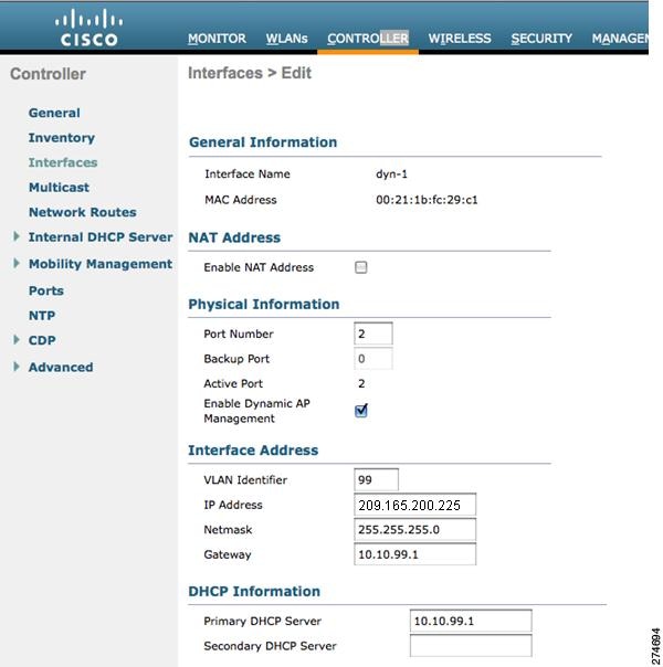
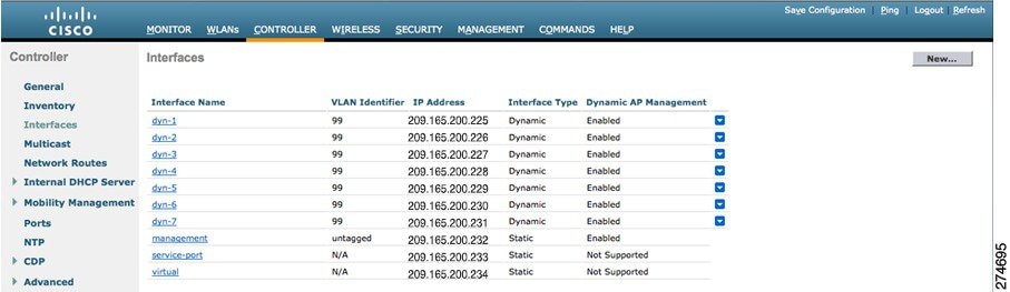
| Step 3 | Enter an interface name and a VLAN identifier, as shown in the figure above.
| ||||||||||||||
| Step 4 | Click Apply to commit your changes. The Interfaces > Edit page is displayed. | ||||||||||||||
| Step 5 | Configure the following parameters:
| ||||||||||||||
| Step 6 | Click Save Configuration to save your changes. | ||||||||||||||
| Step 7 | Repeat this procedure for each dynamic interface that you want to create or edit. |
Configuring Dynamic Interfaces (CLI)
| Step 1 | Enter the show interface summary command to view the current dynamic interfaces. | ||||
| Step 2 | View the details of a
specific dynamic interface by entering this command:
show interface
detailed
operator_defined_interface_name.
| ||||
| Step 3 | Enter the config wlan disable wlan_id command to disable each WLAN that uses the dynamic interface for distribution system communication. | ||||
| Step 4 | Enter these
commands to configure dynamic interfaces:
| ||||
| Step 5 | Enter these commands if you want to be able to deploy your Cisco WLC behind a router or other gateway device that is using one-to-one mapping network address translation (NAT):
NAT allows a device, such as a router, to act as an agent between the Internet (public) and a local network (private). In this case, it maps the controller’s intranet IP addresses to a corresponding external address. The controller’s dynamic AP-manager interface must be configured with the external NAT IP address so that the controller can send the correct IP address in the Discovery Response.
| ||||
| Step 6 | Enter the config wlan enable wlan_id command to reenable each WLAN that uses the dynamic interface for distribution system communication. | ||||
| Step 7 | Enter the save config command to save your changes. | ||||
| Step 8 | Enter the
show interface detailed
operator_defined_interface_name command and
show interface summary command to verify that your
changes have been saved.
|
AP-Manager Interface
Information About AP-Manager Interface
Note | Release 8.2 does not support multiple non-AP Manager dynamic interfaces, untagged management interfaces, management interfaces mapped to physical ports, and non-LAG scenarios. |
Note | A controller configured with IPv6 has only one AP-manager and is applicable on management interface. You cannot remove the AP-manager configured on management interface. |
Note | The controller does not support transmitting the jumbo frames. To avoid having the controller transmit CAPWAP packets to the AP that will necessitate fragmentation and reassembly, reduce MTU/MSS on the client side. |
The AP-manager interface communicates through any distribution system port by listening across the Layer 3 network for access point CAPWAP or LWAPP join messages to associate and communicate with as many lightweight access points as possible.
A controller configured with IPv6 does not support Dynamic AP-Manager. By default, the management interface acts like an AP-manager interface. Link Aggregation (LAG) is used for IPv6 AP load balancing.
Restrictions for Configuring AP Manager Interface
-
For IPv4—The MAC address of the management interface and the AP-manager interface is the same as the base LAG MAC address.
- If only one distribution system port can be used, you should use distribution system port 1.
- An AP-manager interface is not required to be configured. The management interface acts like an AP-manager interface by default, and the access points can join on this interface.
- If link aggregation (LAG) is
enabled, there can be only one AP-manager interface. But when LAG is disabled,
one or more AP-manager interfaces can be created, generally one per physical
port.
-
When LAG is enabled—Supports only one AP Manager, which can either be on the management or dynamic interface with AP management.
-
When LAG is disabled—Supports one AP Manager per port. The Dynamic Interface tied to a VLAN can act as an AP Manager (when enabled).
Note
When you enable LAG, all the ports would lose their AP Manager status and the AP management reverts back onto the Management interface.
-
- Port redundancy for the AP-manager interface is not supported. You cannot map the AP-manager interface to a backup port.
Configuring the AP-Manager Interface (GUI)
| Step 1 | Choose Controller > Interfaces to open the Interfaces page. | ||||||
| Step 2 | Click AP-Manager
Interface.
The Interface > Edit page is displayed.
| ||||||
| Step 3 | Set the
AP-Manager Interface parameters:
| ||||||
| Step 4 | Click Save Configuration to save your changes. | ||||||
| Step 5 | If you made any changes to the management or virtual interface, reboot the controller so that your changes take effect. |
Configuring the AP Manager Interface (CLI)
For Cisco 5508 WLCs, you are not required to configure an AP-manager interface. The management interface acts like an AP-manager interface by default.
A controller configured with IPv6 address does not support Dynamic AP-Manager. The management interface acts like an AP-manager interface by default.
| Step 1 | Enter the
show interface summary command to view the current
interfaces.
| ||
| Step 2 | Enter the show interface detailed ap-manager command to view the current AP-manager interface settings. | ||
| Step 3 | Enter the config wlan disable wlan-number command to disable each WLAN that uses the AP-manager interface for distribution system communication. | ||
| Step 4 | Enter these commands to
define the AP-manager interface:
| ||
| Step 5 | Enter the save config command to save your changes. | ||
| Step 6 | Enter the show interface detailed ap-manager command to verify that your changes have been saved. |
Configuration Example: Configuring AP-Manager on a Cisco 5500 Series Controller
For a Cisco 5508 WLC, we recommend that you have eight dynamic AP-manager interfaces and associate them to the eight Gigabit ports of the controller when LAG is not used. If you are using the management interface, which acts like an AP-manager interface by default, you must create only seven more dynamic AP-manager interfaces and associate them to the remaining seven Gigabit ports.
Note | For IPv6 only—A controller configured with IPv6 address does not support Dynamic AP-Manager. By default, the management interface acts like an AP-manager interface. Use LAG for IPv6 AP load balancing. |
Multiple AP-Manager Interfaces
Information About Multiple AP-Manager Interfaces
When you create two or more AP-manager interfaces, each one is mapped to a different port. The ports should be configured in sequential order so that AP-manager interface 2 is on port 2, AP-manager interface 3 is on port 3, and AP-manager interface 4 is on port 4.
Before an access point joins a controller, it sends out a discovery request. From the discovery response that it receives, the access point can tell the number of AP-manager interfaces on the controller and the number of access points on each AP-manager interface. The access point generally joins the AP-manager with the least number of access points. In this way, the access point load is dynamically distributed across the multiple AP-manager interfaces.
Note | Access points may not be distributed completely evenly across all of the AP-manager interfaces, but a certain level of load balancing occurs. |
Restrictions on Configuring Multiple AP Manager Interfaces
The following restrictions apply while configuring the multiple AP manager interfaces in the controller:
-
You must assign an AP-manager interface to each port on the controller.
-
Before implementing multiple AP-manager interfaces, you should consider how they would impact your controller’s port redundancy.
-
AP-manager interfaces do not need to be on the same VLAN or IP subnet, and they may or may not be on the same VLAN or IP subnet as the management interface. However, we recommend that you configure all AP-manager interfaces on the same VLAN or IP subnet.
-
If the port of one of the AP-manager interfaces fails, the controller clears the state of the access points, and the access points must reboot to reestablish communication with the controller using the normal controller join process. The controller no longer includes the failed AP-manager interface in the CAPWAP or LWAPP discovery responses. The access points then rejoin the controller and are load balanced among the available AP-manager interfaces.
In the case of management interface, because there is support for backup port, APs already connected to management interface continue to be in connected state (falling to backup port) rather than dropping off. However, AP-Mgr will get disabled any new APs will associate with the current AP-Mgr.
Creating Multiple AP-Manager Interfaces (GUI)
| Step 1 | Choose Controller > Interfaces to open the Interfaces page. | ||
| Step 2 | Click New. The Interfaces > New page appears. | ||
| Step 3 | Enter an AP-manager interface name and a VLAN identifier. | ||
| Step 4 | Click Apply to commit your changes. The Interfaces > Edit page appears. | ||
| Step 5 | Enter the appropriate interface parameters.
| ||
| Step 6 | To make this interface an AP-manager interface, select the Enable Dynamic AP Management check box.
| ||
| Step 7 | Click Save Configuration to save your settings. | ||
| Step 8 | Repeat this procedure for each additional AP-manager interface that you want to create. |
Creating Multiple AP-Manager Interfaces (CLI)
| Step 1 | Enter these commands to create a new interface:
| ||
| Step 2 | To make this interface an AP-manager interface, enter this command: {config interface ap-manager operator_defined_interface_name enable | disable}
| ||
| Step 3 | Enter save config command to save your changes. | ||
| Step 4 | Repeat this procedure for each additional AP-manager interface that you want to create. |
Interface Groups
Information About Interface Groups
Interface groups are logical groups of interfaces. Interface groups facilitate user configuration where the same interface group can be configured on multiple WLANs or while overriding a WLAN interface per AP group. An interface group can exclusively contain either quarantine or nonquarantine interfaces. An interface can be part of multiple interface groups.
A WLAN can be associated with an interface or interface group. The interface group name and the interface name cannot be the same.
This feature also enables you to associate a client to specific subnets based on the foreign controller that they are connected to. The anchor controller WLAN can be configured to maintain a mapping between foreign controller MAC and a specific interface or interface group (Foreign maps) as needed. If this mapping is not configured, clients on that foreign controller gets VLANs associated in a round robin fashion from interface group configured on WLAN.
You can also configure AAA override for interface groups. This feature extends the current access point group and AAA override architecture where access point groups and AAA override can be configured to override the interface group WLAN that the interface is mapped to. This is done with multiple interfaces using interface groups.
This feature enables network administrators to configure guest anchor restrictions where a wireless guest user at a foreign location can obtain an IP address from multiple subnets on the foreign location and controllers from within the same anchor controller.
Controller marks VLAN as dirty when the clients are unable to receive IP address using DHCP. The VLAN interface is marked as dirty based on two methods:
Aggressive Method—When only one failure is counted per association per client and controller marks VLAN as dirty interface when a failure occurs three times for a client or for three different clients.
Non-Aggressive Method—When only one failure is counted per association per client and controller marks VLAN as a dirty interface only when three or more clients fail.
Restrictions on Configuring Interface Groups
-
The priority order for configuring VLAN interface select for WLAN is:
-
While you configure VLAN-ACL mapping using the native VLAN identifier as part of Flex group configuration, the ACL mapping does not take place. However, if you use the same VLAN to configure ACL mapping at the access point level, the configuration is allowed.
Creating Interface Groups (GUI)
Creating Interface Groups (CLI)
Adding Interfaces to Interface Groups (GUI)
| Step 1 | Choose Controller > Interface Groups. The Interface Groups page appears with a list of all interface groups. | ||
| Step 2 | Click the name of the interface group to which you want to add interfaces. | ||
| Step 3 | Choose the interface name that you want to add to this interface group from the Interface Name drop-down list. | ||
| Step 4 | Click Add Interface to add the interface to the Interface group. | ||
| Step 5 | Repeat Steps 2 and 3 if you want to add multiple interfaces to this interface group.
|
Adding Interfaces to Interface Groups (CLI)
To add interfaces to interface groups, use the config interface group interface add interface_group interface_name command.
Viewing VLANs in Interface Groups (CLI)
To view a list of VLANs in the interface groups, use the show interface group detailed interface-group-name command.
Adding an Interface Group to a WLAN (GUI)
| Step 1 | Choose the WLAN tab. | ||
| Step 2 | Click the WLAN ID of the WLAN to which you want to add the interface group. | ||
| Step 3 | In the General tab, choose the interface group from the Interface/Interface Group (G) drop-down list. | ||
| Step 4 | Click Apply.
|
Adding an Interface Group to a WLAN (CLI)
To add an interface group to a WLAN, enter the config wlan interface wlan_id interface_group_name command.
 Feedback