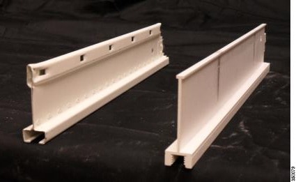
Channel Rail Adapters – Cisco Part Number AIR-CHNL-ADAPTER
When mounting APs to ceiling channel rails, an optional channel adapter AIR-CHNL-ADAPTER is used. The channel adapter comes in a two-pack and is attached to the ceiling grid clip.
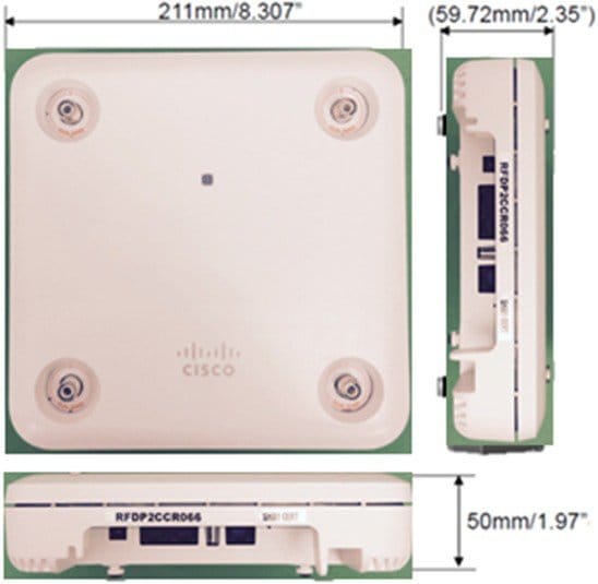
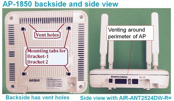
Physical Hardware and Mounting Options of an AP
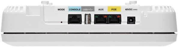
Ports are easily accessible. Mode button is recessed and requires a tool such as a paperclip to engage.
Note the vent holes below the ports, avoid using chemicals or solvents around the AP as the ingress of such materials have the potential to cause damage to the device.
AP 1850 has similar physical dimensions as other Cisco APs but with a few differences in physical appearance, most of which are cosmetic changes to distinguish the different models. The mounting options and bracket configurations are identical and interchangeable between Cisco 1140, 1600, 1700, 1850, 2600, 2700, and 3700 series APs.
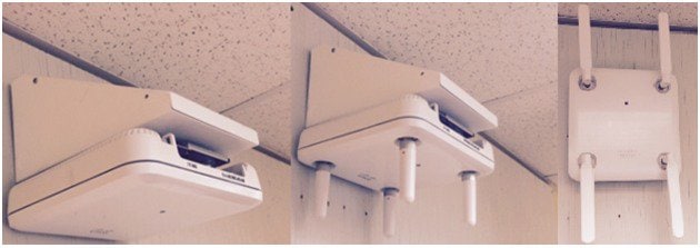
Different installation options are available depending upon the requirements of the customer. Brackets are available from Cisco as well as third-party companies. During the ordering process, the customer may choose one of two brackets (but not both). Each bracket is a zero-dollar ($0) option at the time of configuration. If the customer does not choose a bracket, the selection default is AIR-AP-BRACKET-1, which is the most popular for ceiling installations. The other choice is a universal bracket that carries part number AIR-AP-BRACKET-2.
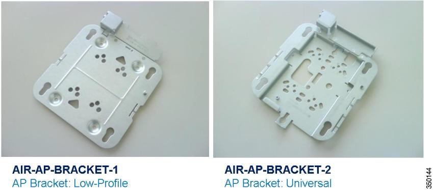
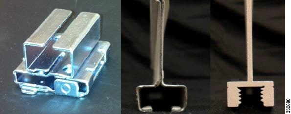
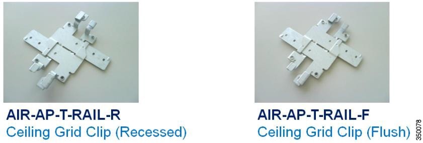
If the AP needs to be mounted directly to a ceiling on the grid work, then AIR-AP-BRACKET-1 is flush mounted and has the lowest profile. However, if the AP is mounted to an electrical box, other wiring fixture, inside a NEMA enclosure, or wall mounted, then AIR-AP-BRACKET-2 is a better choice. The extra space in the bracket allows for wiring, and the extra holes line up with many popular electrical boxes. When mounting the bracket to the ceiling grid work, some ceiling tiles are recessed. For this reason, two different styles of ceiling clips, such as recessed and flush rails are available
Wall Mounting the AP
When the AP needs to be wall-mounted, the installer should understand that walls can be a physical obstacle to the wireless signal. Therefore, maintaining 360 degree coverage may be compromised by the wall. If the wall is an outside wall and/or the goal is to send the signal in an 180-degree pattern instead, a directional antenna, often referred to as a “patch” antenna, may be a better choice assuming that the AP 1850e is used.
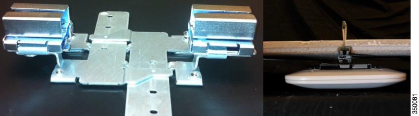
Avoid wall-mounting APs with internal antennas, such as the AP 1850i, unless you use the optional Oberon right-angle mount (Figure 1). The internal antenna model is designed to mount to a ceiling to provide 360-degree coverage. If wall-mounted in a non-ceiling orientation, the signal may penetrate the floor above and below causing unintended coverage. This results in additional and needless roaming access when a mobility client, for example a user with Wi-Fi phone, walks by on an adjacent floor.
Instead, use the AP 1850e (with dipoles or patch antennas) or use an optional wall mount that puts the AP 1850i or AP 1850e into a ceiling type orientation when mounted to a wall.
 Note |
APs with internal antennas such as the AP 1850i that are wall mounted should use the Oberon mounting bracket unless roaming is not an issue, for example, hotspot, kiosk, or small venue scenario. |
Oberon model 1029-00 is a right angle mount works with “i” and “e” models to put the AP in the right antenna orientation. If the unit is an “e” model with dipoles that can be mounted (far right), then an Oberon wedge mount is not required.
See http://www.oberonwireless.com/WebDocs/Model1029-00_Spec_Sheet.pdf.
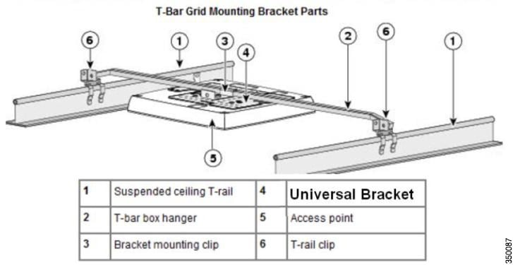
Above the Ceiling Tiles
The AP 1850 series is rated for installation in the Plenum area (UL-2043). Many customers prefer to locate the AP in such a way that nothing is visible on the ceiling. In some cases, this is preferred for aesthetic reasons, so customers may install the AP above a drop ceiling. This may also be preferred in high theft areas such as classrooms or in areas where policy dictates that nothing can be visible on the ceiling.
To meet this hard requirement, optional T-Bar hangar accessories such as Erico and Cooper, can be used (Figure 1). These accessories are manufactured by third-party companies. The Erico Caddy 512a, the Cooper B-Line BA50a, or similar T-Bar Grid T-Bar hangars can be used.
For more information, see:
Note |
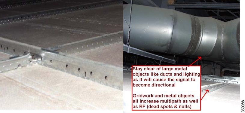
Installing APs above the ceiling tiles must be done only when mounting below the ceiling is not an option. The tiles must not be conductive; such installations will degrade advanced RF features such as voice and location, so verify coverage and performance. Always, try to mount the AP as close to the inside middle of the tile as possible, and avoid areas with obstructions |
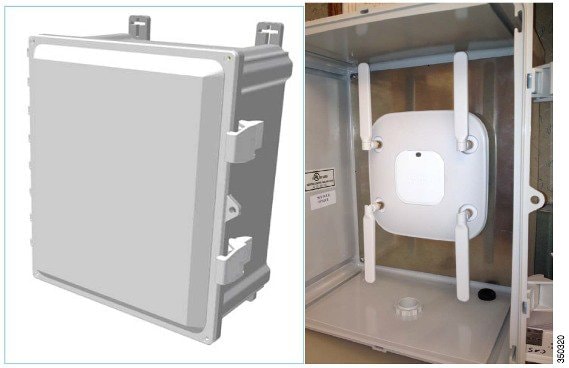
Stadium / Harsh Environments
Customers needing to install the APs in harsh environment such as sporting areas, stadiums, open garden areas, or warehouse freezers, where it may be exposed to weather, may use a NEMA type enclosure.
Note |
Some APs may not be certified for outdoor deployments in a NEMA enclosure. This varies around the world, for example some regulatory agencies permit AP outdoor NEMA enclosures if the AP is indoors such as a freezer or garden area but may prohibit its usage outdoors. This seems to vary with regard to weather radar compliance, UNII-1 compliance, and so on. Check with your Cisco account team or the communications regulatory agency that has jurisdiction in your area. |
Third-party sources for NEMA type enclosures include:
When using a NEMA type enclosure, ensure that the cables exit out of the bottom of the enclosure so that rain and moisture do not run down the cable into the enclosure. Also, the color of the enclosure may affect the heat rating; for example, a black enclosure gets much hotter in the sun than a white one. You may also want to use a pressure vent to prevent moisture accumulation.
Ethernet Cable Recommendation
While the AP 1600, 1700, 1850, 2600, and 3600 work fine with CAT-5e cable, for newer cable installations, it is recommended that the customers use CAT6a. Because, CAT6a is the cabling required by the 10GE standard.
Antenna Cable Recommendation
Whenever practical/possible, ensure that the antenna cable runs as short as possible. Cisco offers low loss (LL) and ultra low loss (ULL) cables, which have the same characteristics as Times Microwave LMR-400 and LMR-600.
Cisco cables carry the part number AIR-CAB (Aironet Cable) and its length parameter. For example, a 20 Ft length of LL cable with RP-TNC connector is Cisco AIR-CAB-020LL-R. These heavy black cables are not Plenum rated and are primarily for outdoor use or manufacturing areas.
Access Point Spacing Recommendations
If you have an Wi-Fi device such as an AP and you are going to use another AP in the vicinity on a different channel, it is recommended that you space each AP apart by approximately 6 ft (2 meters). Avoid clustering the APs or the antennas from different APs together, because this could cause degradation in performance. This recommended distance is based on the assumption that both devices operate in the unlicensed band and do not transmit RF energy more than 23 dB, that is, 200 mW. If higher power is used, space the APs farther apart.
If you have other devices that transmit, especially if they operate in the same frequency ranges, for example, frequency hopping legacy APs or other devices that operate close in frequency to those of the AP (think below or above the 2.4 and 5 GHz band), you should consider moving or separating the devices as far as you can. After you have done this, check for interference by testing both devices at the same time under heavy utilization (load) and then characterize each system independently to see how much, if any, degradation exists.
 Warning |
To comply with FCC, EU, and EFTA RF exposure limits, antennas should be located at a minimum of 7.9 inches (20 cm) or more from the body of all persons. For more information, see the Declarations of Conformity section in the Cisco Aironet 1850 Series Access Points Hardware Installation Guide. |
Installations in IDF Closets (Telecommunications or Other Electrical Equipment)
When installing APs near electrical or telecommunications equipment, keep all wiring and metal away from the antennas and avoid placing the antennas near electrical lines. Do not route wiring electrical or Ethernet in the near field (6-15 inches) from the antenna. Try to refrain from installing the AP in the electrical closet, because the best place for the AP is as close to users as possible/practical. If you have remote antenna cables from such a closet, you may be required to use Plenum rated cable (see local fire/safety regulations for more on this).
Below are a few URLs for understanding interference:
http://www.cisco.com/en/US/prod/collateral/wireless/ps5678/ps10981/white_paper_c11-609300.html
Installations Inside and Around Elevators
Elevator coverage can sometimes be accomplished by placing APs in the near field of an elevator, typically on each floor near the elevator door. Because, elevators often have metal doors and the shafts are often concrete or contain other materials that degrade Wi-Fi coverage. It is important to check the coverage inside the elevator. Though such coverage can be challenging, it is often do-able, especially if the elevator is only a few floors.
High rise elevators are more challenging because roaming issues are problematic; the client is cycling through a large number of APs quickly. Some companies that do in-elevator advertising put a patch antenna on the floor inside the shaft and a patch antenna on the bottom of the elevator car, while other companies use leaky coaxial cable running on the side of the shaft.
When installing any Wi-Fi equipment inside the elevator cars or shafts, local regulations need to be followed. Because, many times such installations are prohibited either for safety reasons or because the building owner or local fire department may prohibit the same. Only elevator repair persons or contractors who have experience with this kind of work should be in those areas.
Understanding AP 1850 Powering Options
PoE Negotiation
When the AP negotiates 802.3at (high power), it always tries first to negotiate using Cisco Discovery Protocol (CDP). If the negotiation fails, the AP will attempt to negotiate using Link Layer Discovery Protocol (LLDP). LLDP is a vendor-neutral method for advertising device identity and capabilities.
So, the AP 1850 first uses CDP to get 20.9 W and reserve that amount of power. If CDP fails, the same process starts using LLDP. So, a non CDP response time out (often approaching 60 seconds) would need to occur before the LLDP negotiation starts. In both cases, the requirement is obtain 20.9 W power.
If the AP has enough power, it shows Full Power in the PoE settings. See Figure 1.
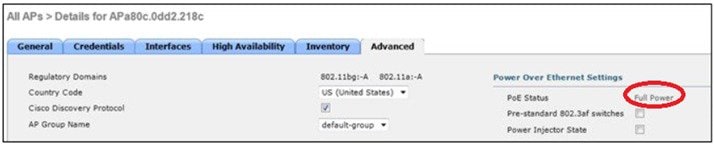
However, if the power source equipment such as PoE switch, mid-span, or injector lacks the ability to properly negotiate high power, go to “ANY” mode and take whatever power the device can provide, which would likely be 15.4 W (802.3af).
If the power source is limited to 15.4 W (802.3af), then the AP negotiates and reserves 15.4 W.
The AP functions with the available power sourcing. If the power is not enough to be fully functional, then the AP makes an effort to shut down and re-negotiate to be able to function at 15.4W. Also, the AP indicates LOW or MEDIUM power on the controller and functions at reduced capability. See Table 1.
Note |
If the power source does not support Cisco Discovery Protocol, for example third party switch, then uncheck its usage. See Table 1. |
|
Powering Options |
Power Budget 1 |
Capability |
|---|---|---|
|
802.3at, Enhanced PoE, PoE+ |
19.93 W |
Fully Functional |
|
Cisco Power Injector AIR-PWRINJ4=(30 W) |
19.93 W |
Fully Functional |
|
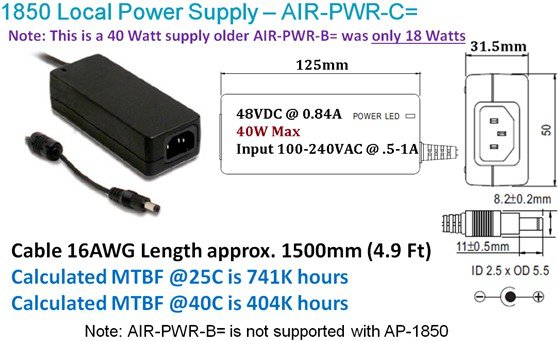
Cisco Local Power Supply, AIR-PWR-C= |
19.93 W |
Fully Functional |
|
802.3af, Cisco Power Injector AIR-PWRINJ5= |
12.95 W |
1852i: Full radio function 1852e: 2.4 GHz radio will shift to 2x3 AUX and USB port disabled for both 1852i/e |
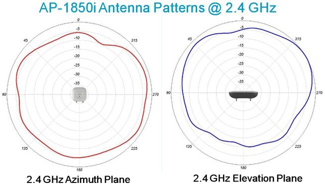
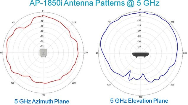
Approved antennas and Radiation Patterns
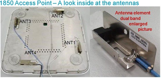
The internal antennas are rated at 3 dBi at 2.4 GHz and 5 dBi at 5 GHz.
Antennas for Outdoor Deployments
The AP 1850 is designed for indoor deployments. However, using a NEMA enclosure or mounting the antenna outdoors may be acceptable (depending upon your location as some countries do not permit this).
In the U.S., installers who need to deploy APs outdoors are recommended to use the “P” series products such as the Cisco Aironet AP 3600P and AP 3700P. For more information, See the 3700 deployment guide.
All Cisco antenna connectors are labeled as “A,” “B,” “C,” and so on. “A” has a higher priority than “B” or “C/D”. So, if the AP supports, for example 3 or 4 antennas and you only have 2 antennas, you can use them on ports “A” and “B” for a short period until you install the additional antennas provided you turn off the unused antenna ports on the controller or AP software.
While it is not recommended to use less antennas, the product (in a pinch) supports 802.11a/b/g clients or single spatial stream .11n clients using only one or two antennas. However, there is a significant performance hit and you will also lose ClientLink functionality. If you do this, you will also have to configure the AP in the software to not use the other antenna. Failure to do so could result in performance issues.
-
AIR-ANT2524DB-R= Dipole Black 2dBi @ 2.4 GHz – 4dBi @ 5 GHz
-
AIR-ANT2524DG-R= Dipole Gray 2dBi @ 2.4 GHz – 4dBi @ 5 GHz
-
AIR-ANT2524DW-R= Dipole White 2dBi @ 2.4 GHz – 4dBi @ 5 GHz
-
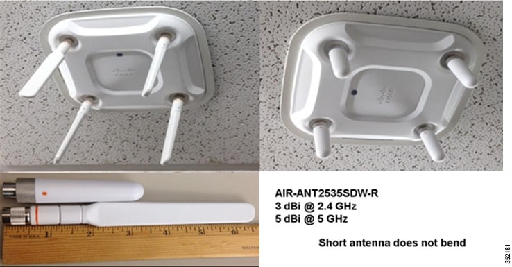
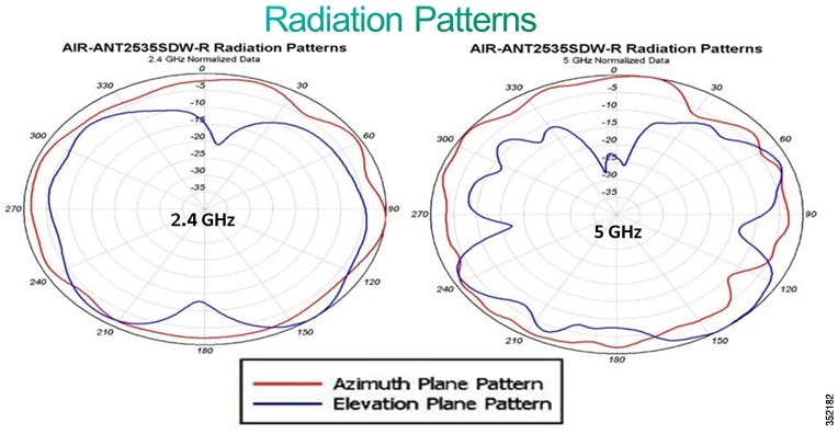
AIR-ANT2535SDW-R= Short Dipole 3dBi @ 2.4 GHz – 5dBi @ 5 GHz
-
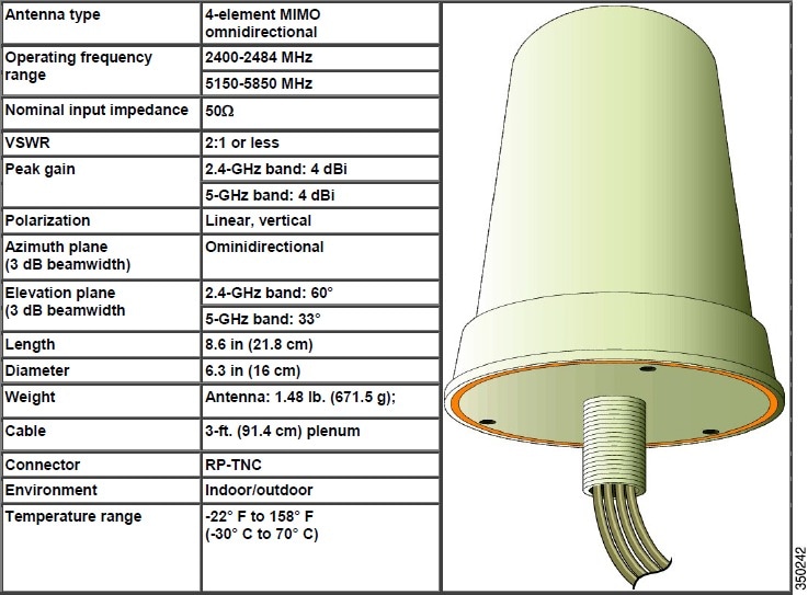
AIR-ANT2524V4C-R= MIMO Omni Ceiling 2dBi @ 2.4 GHz – 4dBi @ 5 GHz
-
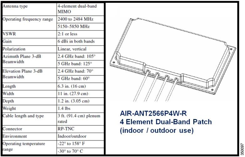
AIR-ANT2566P4W-R= MIMO Patch 6dBi in both bands
-
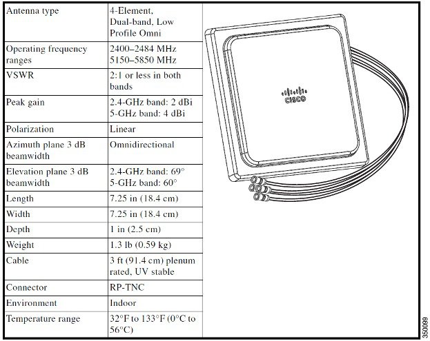
AIR-ANT2544V4M-R= MIMO Wall Mount Omni 4dBi in both bands
-
AIR-ANT2566D4M-R= Medium Ceiling / Auditorium Patch 6dBi in both bands
For additional information on Cisco antennas, see Cisco Aironet Antennas and Accessories Reference Guide.
The antenna reference guide has details of all Cisco antennas. You can also find individual data sheets at http://www.cisco.com/en/US/products/hw/wireless/ps469/index.html.
Note |
Always use Cisco antennas whenever possible. See http://www.cisco.com/en/US/prod/collateral/wireless/ps5678/ps10981/white_paper_c11-671769.pdf. |
Cisco has also introduced a new smaller size dipole. While this antenna does not have an articulating knuckle, it is much smaller in size and is a good choice when aesthetics is a primary concern. Figure 1 shows an AP-3700 with both types of dipoles.
In addition, the antennas below may also be used with 1600, 1850, 2600, 3600, and 3700 “e” Series APs.
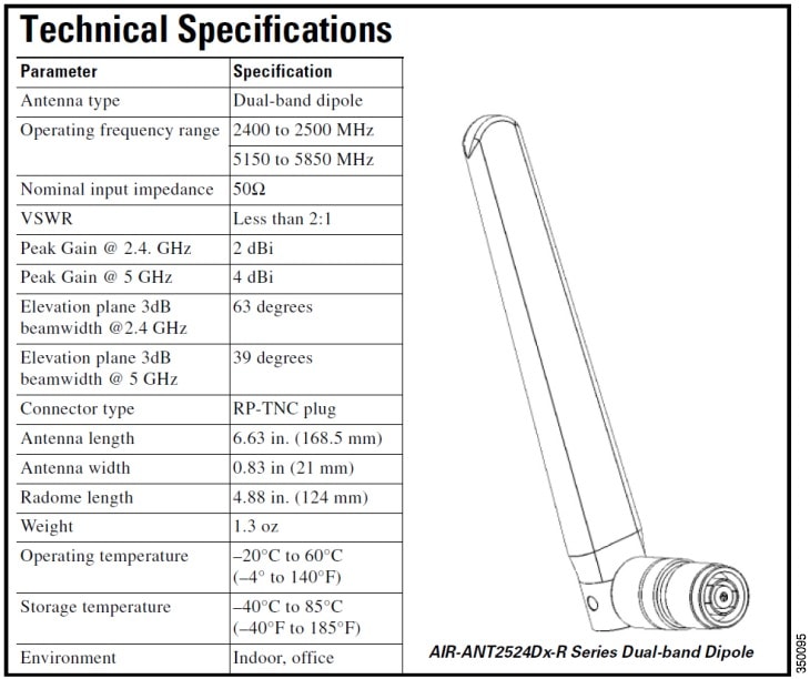
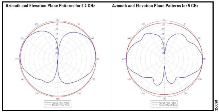
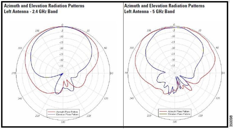
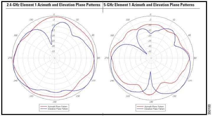
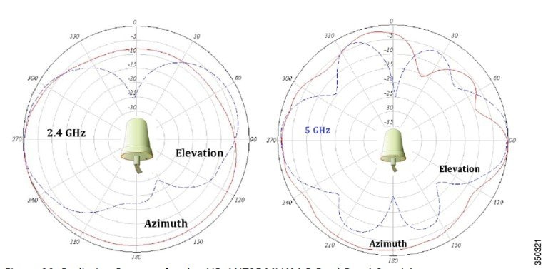
Assuming that the antenna is mounted on a wall, the Azimuth (in Red) is the signal going forward from the antenna. The elevation, in Blue, is the “up/down” pattern.
Note |
For a granular pattern, see the individual specification sheet of the respective antennas. |
General Considerations – WLAN Best Practice Guidelines
-
Always try to mount the AP as close to the users as possible for best performance. Be aware of the environment; for example, hospitals have metal doors and coverage can change when the doors close. Old buildings can have metal grid work in the plaster or asbestos. Avoid mounting the AP or antennas near metal objects, as doing so can change the coverage area.
-
When using the 2.4 GHz frequency, the same 1, 6, and 11 channel scheme is used as the 5 GHz channel scheme (Figure 1). Avoid putting all the APs on the same channel, and reuse channels as you can. See other deployment guides for more on this topic.
Figure 29. Example of Channel Usage in 2.4 and 5 GHz (Two Channels used if 40 MHz) 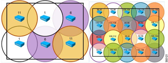
-
Try to determine which clients are going to be used and check the coverage using those clients. For example, a PDA or Wi-Fi phone might not have the same range as a notebook or tablet.

Tip
Verify coverage using the worst performing clients that you intend to deploy.
-
The Cisco AP 1850 series supports standards based transmit beamforming and is positioned for newer Wave-2 MU-MIMO and 4-SS clients. The Cisco 2700 and 3700 series APs with ClientLink 3.0 will perform better than the AP 1850 when using legacy .11g/n and .11ac Wave-1 clients. This is because the performance improvements with the AP 1850 are designed to take advantage of 4-SS and Multi-User MIMO (Wave-2 clients) and does not support Cisco’s enhanced Client Link beamforming for legacy clients.
-
While site surveys are generally recommended, if the design is done at half power and Cisco RRM is in place, sometimes a limited site survey (coverage check) is adequate for smaller venues. If it is a very challenging environment such as train connectivity, Gas & Oil verticals, large hospitals, and so on, Cisco has an Advanced Services team that can be contracted to help you get up to speed or perform your installation. Contact your Cisco account team for more information.
-
The rule of thumb coverage plan is 1 AP per 5,000 square feet for data and 1 per 2,500 square feet for voice and location services, which roughly means 1 AP per 50 feet for best performance.
-
Try to leverage 5 GHz for more and cleaner channels / spectrum.
-
Try to create 10 – 20% cell overlap for optimized roaming and location calculations / transactions.
-
Consider separate SSIDs for Corporate and Guest Access with Guest being Rate Limited.
-
Enable band steering, so that the dual band clients are motivated to use 5 GHz to avoid slower 2.4 GHz channels.
-
Use Category 5E or better for Gigabit Ethernet or mGig.
-
Some clients (especially older ones) do not support the UNII-2 extended client channels 100 – 140. So, if you have lots of older clients, you may need to disable them in the DCA channel list.
Note |
Clients with later chipsets (especially later 802.11ac clients) should support extended UNII-2 channels. |
-
-65 to -67 = Data, Voice, Video, Location, High Density
-
1 access point per 2,500 square feet / every 50 feet
-
-
-68 to -69 = Data, Voice, Multicast and Unicast Video, Location
-
-70 to -71 = Data, Unicast Video
-
-72 or greater = Data only
802.11ac Wave-2 primer and the AP 1850
For an overview of 802.11ac, see the technical white paper at the following URL:
-
The ability to use 1, 2, 3 (and now 4) Spatial Streams
-
An extra Spatial Stream gives you a bump in data rate @ 80 MHz 1733 versus1300 Mbps
-
Same channel bonding 20, 40, 80 (does not support 160 MHz)
-
11ac Beamforming (was in Wave-1) now implemented, but only 11ac clients participate in .11ac beamforming
-
Multi-User MIMO (MU-MIMO) support—supported in Wave-2 for 11ac Wave 2 clients only
-
Based on IEEE 802.11ac final standard—ratified Dec’2013
Clients Supporting 3 and 4 Spatial Streams
Clients with 3SS support are starting to become a commonplace with 4SS and MU-MIMO Wave-2 clients on the horizon. As the new 802.11ac specification starts to get traction, many newer client adapters will have more advanced chipsets and support 3SS and 4SS as a subset to 802.11ac. Additionally, the Cisco AP 1850 fully supports all the DFS frequencies for more usable channels in the 5 GHz range. More clients, especially 802.11ac clients, will start supporting these newer channels in legacy 802.11n modes as well.
Currently, the most popular 3SS client is the Apple 2011 MacBook Pro, because it is based upon the Broadcom BCM4331 chipset and a small USB adapter by Trendnet, that is, TEW 684UB, based on the Ralink chipset.
Additionally, the Intel 5300 and 6300 modules have supported 3SS for a long time. Because of the different types of notebooks that these cards are installed in, testers have observed good throughput on many notebooks (+320 Mbps) and reduced throughput on other notebooks such as 240 Mbps. If you experience low throughput using the Intel card, you may try a MacBook Pro or Trendnet adapter. If they perform well, try another notebook with the Intel card or open a case with Intel or the laptop manufacturer for a possible remedy. During the AP 3600 beta trials, Cisco observed differences in performance with different notebooks using the Intel 6300 card.
Note |
Sometimes, it can be difficult to reliably maintain a 3SS link because it is easy for the client to rate-shift out of the 3SS mode. The client plays an important role in the ability to maintain a 3SS link, so it can vary with the quality of the client being used and the test environment. |
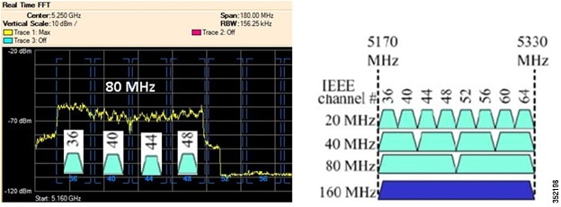
Understanding Channel Plans and Bonded Channels
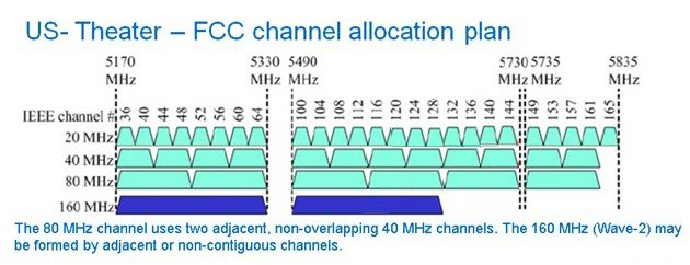
Currently in the US, there are 25 (20 MHz) channels, 12 (40 MHz) channels, and 6 (80 MHz) channels. 802.11ac (Wave-2) supports 160 MHz channels but currently there are only two channels available. This is likely to get better, because the Federal Communications Commission and other regulatory bodies realize the need for more unlicensed spectrum and are actively working to free up more spectrum.
Let us take a look at the frequencies available and how the channel bonding would work.
Right now in the US, there are only four 80 MHz channels but this is likely to improve.
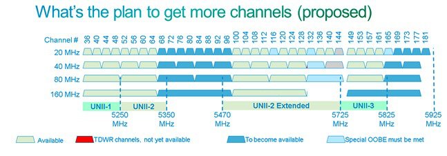
Future of spectrum allocation?
-
In the US, there are currently 25/12/6/2 channels with bandwidth 20/40/80/160 MHz channels.
-
With the opening up of 5.35 – 5.47 GHz and 5.85 – 5.925 GHz, the number of channels increases to 34/16/8/3.
-
If the industry manages to take back the TDWR channels, the number increases to 37/18/9/4.
So, as time progresses, you should see additional channels becoming available.
Summary
-
802.11ac deployments and surveys are not much different than 802.11n deployments.
-
802.11ac supports faster 256 QAM modulation allowing 802.11ac clients the ability to use faster and a wider range of data rates, thus permitting clients to maintain higher connectivity rates.
- When deploying 80 MHz bonded channels, ensure that you have enough spectrum for 80 MHz channels. Note that this can be a major change to your existing spectrum plan.
Understanding Channels and How They Relate to the Client
Most clients (USB) that are emerging are 2 spatial stream, and by using 80 MHz bonding, you can achieve up to 866 Mbps. Figure 1 shows the Netgear A6200 client card.
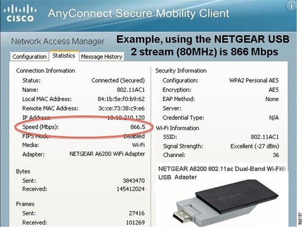
Note |
The software reports channel is 36 (this is where the channel bonding starts). On a spectrum analyzer, you can see that the actual channels in use are 36, 40, 44, and 48. |
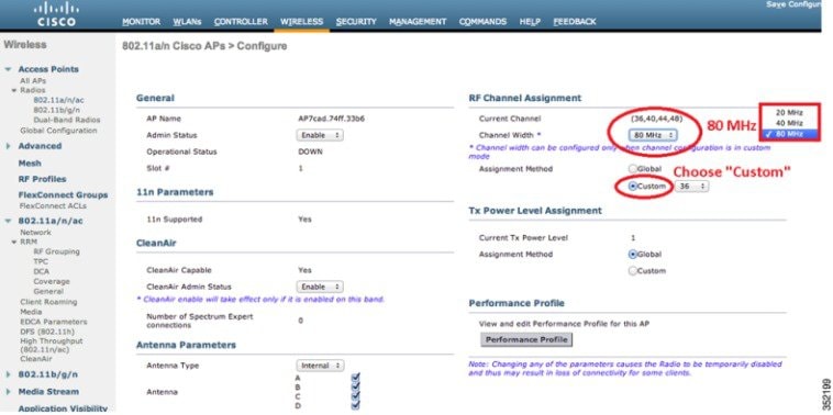
Note |
For clients to link at 80 MHz, you have to set the channel width to 80 MHz on the AP. |
802.11ac and Legacy Client Recommendations
Devices such as Samsung Galaxy S4, ZTE’s Grand Memo, HTC One, and new notebooks such as the Apple 2013 Macbook Pro are the first to market 802.11ac devices. It is expected that integrated notebooks and tablets (those devices often supporting 2 and 3 spatial streams) will start to become a commonplace.
Currently, Cisco’s test bed for interoperability has the following configuration types.
|
Hardware/Software Parameter |
Hardware/Software Configurations Type |
|---|---|
|
Release |
8.1 |
|
Controller |
Cisco 5500 Series Controller |
|
Access Points |
1131, 1142, 1242, 1252, 1850, 3500e, 3500i, 3600, 3702 |
|
Radio |
802.11ac, 802.11a, 802.11g, 802.11n2, 802.11n5 |
|
Security |
Open, WEP, PSK (WPA and WPA2), 802.1X (WPA2-AES) (LEAP, PEAP, EAP-FAST, EAP-TLS) |
|
RADIUS |
ACS 4.2, ACS 5.2 |
|
Types of tests |
Connectivity, traffic, and roaming between two access points |
Interoperability matrix for APs, Clients and security types tested with the below clients.
|
Client Type and Name |
Version |
|---|---|
|
Laptop |
|
|
Intel 3945/4965 |
11.5.1.15 or 12.4.4.5, v13.4 |
|
Intel 5100/5300/6200/6300 |
— |
|
Intel 1000/1030/6205 |
v14.3.0.6 |
|
Intel 7260(11AC) |
v14.3.0.6 |
|
Broadcom 4360(11AC) |
16.1.5.2 |
|
Dell 1395/1397/Broadcom 4312HMG(L) |
XP/Vista: 5.60.18.8 Win7: 5.30.21.0 |
|
Dell 1501 (Broadcom BCM4313) |
v5.60.48.35/v5.60.350.11 |
|
Dell 1505/1510/Broadcom 4321MCAG/4322HM |
5.60.18.8 |
|
Dell 1515 (Atheros) |
8.0.0.239 |
|
Dell 1520/Broadcom 43224HMS |
5.60.48.18 |
|
Dell 1530/Broadcom BCM4359 |
v5.100.235.12 |
|
Cisco CB21 |
v1.3.0.532 |
|
Atheros HB92/HB97 |
8.0.0.320 |
|
Atheros HB95 |
7.7.0.358 |
|
MacBook Pro (Broadcom) |
5.10.91.26 |
|
MacBook Air |
OSX 10.8.5, BCM43xx 1.0 (6.30.223.154.45) |
|
Handheld Devices |
Version |
|---|---|
|
Apple iPad |
iOS 5.0.1 |
|
Apple iPad2 |
iOS 7.0.3 (11B511) |
|
Apple iPad3 |
iOS 7.0.3 (11B511) |
|
Asus Transformer |
Android 4.0.3 |
|
Sony Tablet S |
Android 3.2.1 |
|
Toshiba Thrive |
Android 3.2.1 |
|
Samsung Galaxy Tab |
Android 3.2 |
|
Motorola Xoom |
Android 3.1 |
|
Intermec CK70 |
Windows Mobile 6.5 / 2.01.06.0355 |
|
Intermec CN50 |
Windows Mobile 6.1 / 2.01.06.0333 |
|
Symbol MC5590 |
Windows Mobile 6.5 / 3.00.0.0.051R |
|
Symbol MC75 |
Windows Mobile 6.5 / 3.00.2.0.006R |
|
Phones and Printers |
Version |
|---|---|
|
Cisco 7921G |
— |
|
Cisco 7925G |
1.4.2.LOADS |
|
Ascom i75 |
1.8.0 |
|
Spectralink 8030 |
119.081/131.030/132.030 |
|
Vocera B1000A |
4.1.0.2817 |
|
Vocera B2000 |
4.0.0.345 |
|
Apple iPhone 4 |
iOS 7.0.3 (11B511) |
|
Apple iPhone 4S |
iOS 7.0.3 (11B511) |
|
Apple iPhone 5 |
iOS 7.0.3 (11B511) |
|
Apple iPhone 5S |
iOS 7.0.3 (11B511) |
|
Ascom i62 |
2.5.7 |
|
HTC One (11AC) |
Android 4.2.2 |
|
Samsung Galaxy S4 - GT-19500 (11AC) |
Android 4.3 |
|
HTC Sensation |
Android 2.3.3 |
|
RIM Blackberry Pearl 9100 |
WLAN version 4.0 |
|
RIM Blackberry Pearl 9700 |
WLAN version 2.7 |
802.11ac Devices on the Market
-
Integrated Devices – Shipping
-
Apple - Macbook Air
-
Intel Dual Band Wireless - AC 7260
-
Samsung S4
-
HTC ONE
-
ZTE Grand Memo
-
-
USB Clients - Shipping
-
LinkSys AE6000 1x1
-
Asus – USB-AC53 2x2
-
NetGear – A6200 2x2
-
Belkin P-F9L1106 - 2x2
-
D-Link DWA-182 – 2x2
-
Buffalo ac866 – 2x2
-
Edimax EW-7822AC– 2x2
-
-
Ethernet to 802.11ac Bridges - Shipping
-
LinkSys (Belkin) WUMC710
-
Buffalo WLI-H4-D1300
-
-
List for identifying new 802.11ac hardware:
Variables Impacting Performance
Some early observations show that USB clients can appear to be a bit slow in performance depending on drivers, USB port versions, and so on. Also, it is observed that some clients have trouble in maintaining an 80 MHz bandwidth in the Dynamic Frequency Selection (DFS) bands. Table 1 lists the clients that had reasonable success during testing.
|
Spatial Streams |
Interface |
DFS |
Driver |
|
|---|---|---|---|---|
|
Samsung Galaxy S4 |
1ss |
Integrated |
Yes |
4.1.2 |
|
HTC One |
1ss |
Integrated |
Yes |
4.1.2 |
|
Linksys AE6000 |
1ss |
USB 2.0 |
Yes |
5.0.7.0 |
|
MacBook Air |
2ss |
Integrated |
Yes |
10.8.4 |
|
Intel 7260 |
2ss |
Mini PCIe |
Yes |
16.1.5 |
|
Edimax EW-7822UAC |
2ss |
USB 3.0 |
Yes |
1024.2.618.2103 |
|
Linksys WUMC710 |
3ss |
Bridge |
No |
1.00 |
|
MacBook Pro |
3ss |
Integrated |
Yes |
10.9 |
Wi-Fi is a highly variable technology and there are many factors that could impact performance. Few examples are: environment, client, channel, AP placement, and client distance from the AP.
Is the spectrum clean?
If you are not seeing the results you expect, you need to first check the coexistence with other Wi-Fi networks. Also, you need to ensure the entire 80 MHz wide channel or whatever you have bonded together is clear. The easiest way to confirm this is to put your 3600/3700 into SE Connect mode and have a look on Spectrum Expert or Metageek Chanalyzer Pro. This will allow you to see Wi-Fi and non-Wi-Fi interference on all channels.
What client are you using?
The client will have a big impact on performance. First, you need to check if the client is 1, 2, or 3 spatial stream? Then, check the interface used? A USB 3.0 client performs much better than a USB 2.0 client. Integrated radios are the best of all, because they can take advantage of a fast bus speed as well as the built-in antennas of the device. So, it is recommended to use devices such as the Samsung Galaxy s4 (1x1) or the Apple MacBook Air (2x2) over USB clients. We certainly recommend USB 3.0 products over USB 2.0 products.
What channel are you using?
If you are doing a Rate versus Range demo, it is important to choose your channel carefully. Obviously, you need to ensure that the channel is clear. However, not all channels are created equal. Some channels have total output power restrictions. So, Cisco recommends UNII-3 or UNII-2, over UNII-1 for best performance.
How far is the client from the access point?
Check how far is the client from the AP. 802.11ac introduces 256 QAM, which is a more complex modulation. So, the modulation is harder to maintain over distance. If you want to consistently show 256 QAM, which equates to m8 and m9, it is recommended to keep the client within 25’. Beyond 25’, you will still see m8/m9, but not consistently.
Keep in mind, m7 is the same for 11n and 11ac, the difference being, 11ac allows for 80 MHz channels. Under ideal conditions, you can expect 11ac to have an almost 3x gain over 11n at m9 and a 2x gain at m7.
How is the AP mounted?
AP placement needs to be considered. For close-in tests, less than 10’, placement is not so important. Just make sure that the AP is not obstructed. For other tests, you must take care to mount the AP in a proper location (ceiling or high on a wall in the right orientation).
Try to follow these best practices: avoid mounting the AP near metal, mount it horizontally on a ceiling, and so on.
What data rate is the AP transmitting to the client at?
It is often useful to monitor the data rate of the client. The data rate has a direct impact on performance. There are several ways to monitor the data rate. The easiest method is to check on the GUI.
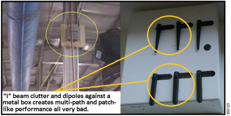
A Quick Look at a Few Non-Optimal Installations
This section lists some examples of installations that are not recommended. It is very difficult to provide good Wi-Fi service with a poor installation. Always try to avoid metal and clutter.
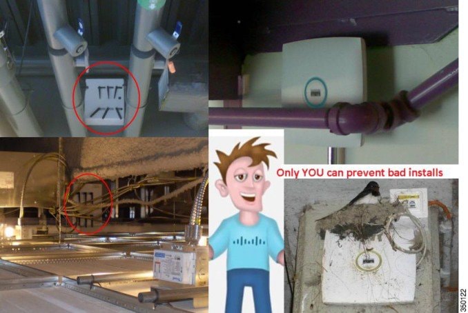
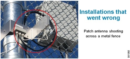
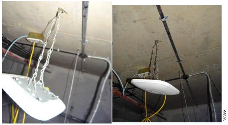
When mounting devices, the AP should be level and secured so that it does not sway or move. Keep the AP away from metal objects and try to place it as close to the users as possible.
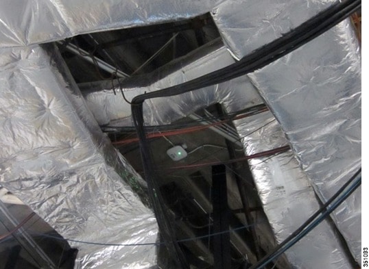
Remember, the best place for an AP is as close to the users as possible. Avoid metal or conductive objects in the near field (they cause the radio waves to become directional and increases nulls (dead spots)). If you must mount the AP in a high ceiling, look at directional antennas to direct (angle down) the signal to the intended target area and always mount dipoles in the correct orientation.
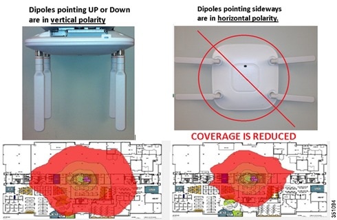
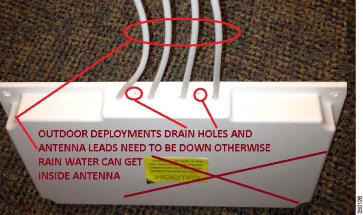
Tip |
When mounting antennas outside, always mount with the WIRES DOWN and never obstruct or put weather proofing material over the drain holes. |
New features
Auxiliary Ethernet Port
AP 1850 has an additional Ethernet port labeled "AUX", that is, Auxiliary port used for LAG connection to the Ethernet switch supporting LAGB or for downstream traffic. The Ethernet uplink port to the controller on the AP 1850 is labeled "PoE".
Link Aggregation for the AP 1850
Many Ethernet switches support links up to 1 Gbps throughput. However, with newer Wave-2 access points such as the AP 1850, it is possible (or at least the potential exists) that the AP traffic could exceed 1 Gbps. It is not likely to occur until MU-MIMO and 4 spatial stream Wave-2 clients become more commonplace.
To address this potential issue, we have implemented Link Aggregation into the Cisco AP 1850.
Link Aggregation is the only method to gain higher throughput on AP 1850 as it does not support multi-gigabit technologies such as NBase-T.
For more on multigigabit technology, see the following URL:
Note |
It is expected that future Wave-2 access points may support multigigabit functionality. |
Cisco Switches Supporting Link Aggregation
-
Catalyst 3850 / all models (non-CA mode)
-
Catalyst 3650 / all models (non-CA mode)
-
Catalyst 4500/Sub-8E
Enabling link aggregation on the AP 1850
Procedure
| Step 1 |
Enable the controller to support LAG for all APs using the command: config ap lag-mode support enable This will NOT result in a reset and reboot of the APs that support LAG. To disable the LAG on all APs, use the command: config ap lag-mode support disable This will result in a reset and reboot of all the APs that support LAG. |
||
| Step 2 |
Enable LAG mode on the individual AP 1850 using the command: config ap lag-mode support <ap-name> enable To disable the LAG on the AP, use the command: config ap lag-mode support <ap-name> disable
|
||
| Step 3 |
For optimal traffic load balancing on the LAG ports to the AP and the controller, it is important that the switch support balancing is based purely on the L4 source and destination ports. A sample configuration on the Cisco 3850 switch is shown below, where the AP 1850 is connected to G6/0/13 and G6/0/3 on the wired0(plink) and wired1 (Aux port) respectively.
|
||
| Step 4 |
The state of the LAG configuration on the controller and AP can be seen using the following commands on the controller: show ap lag-mode show ap config general <ap-name> The successful formation of LAG between AP and the switch can be seen using the following commands on the switch: show lacp neighbors show lacp internal
|
Downstream Device connection for the AP 1850
The AUX port is designed to function as a downstream port. The AUX port is ideal for devices such as video cameras, projectors, IP Phones, Point of Sale terminals, and other end point devices. Also, it is designed to perform port Link Aggregation (LAG).
Additionally, this AUX port will be disabled if the AP is powered by a limited 15.4 W .3af PoE source because it requires PoE+, .3at, or local power (wall brick type power supply) to properly function.
Note |
The AUX port is not manageable and is simply bridged back to the controller. Avoid connecting another AP to this port or devices such as switches/hubs or the same switch or uplink as the PoE port because it can create spanning tree loop issues. |
For example, if you configure the switch port (to AP 1850) as access in VLAN 5, then the traffic comes from the AUX port.
If you configure the switch port to trunk, the AP 1850 will be in the native VLAN and the AUX port will also be in native by default. Traffic from the AUX port will not be sent to the WLC, and the AP 1850's built-in switch will drop the traffic in the native VLAN.
Note |
This feature will not be implemented on the initial release of the code. The initial release will only support LAG. |
USB Port
The USB port is not enabled in the first release of this software. This will be enabled in the later release.
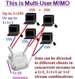
Understanding Multi-User MIMO
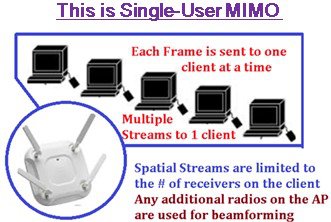
With 802.11n, a device can transmit multiple spatial streams at once, but only directed to a single address. For individually addressed frames, only a single device (or user) gets data at a time. This is referred to as Single-User MIMO (SU-MIMO). With the advent of 802.11ac Wave-2, a new technology is defined, called Multi-User MIMO (MU-MIMO). Using this technology, an AP can use its antennas and radio systems to transmit to different clients, all at the same time over the same frequency spectrum.
MU-MIMO with the AP 1850 is limited to a maximum of 3 spatial streams simultaneously.
To send data to user 1, the AP forms a strong beam towards user 1, shown as the top right lobe of the blue curve (Figure 3). At the same time the AP minimizes the energy for user 1 in the direction of user 2 and user 3. This is called “null steering” and is shown as the blue notches. In addition, when the AP sends data to user 2, it forms a beam towards user 2, and forms notches (nulls) towards users 1 and 3, as shown by the red curve. The yellow curve shows a similar beam towards user 3 and nulls towards users 1 and 2. In this way, each of users 1, 2, and 3 receives a strong copy of the desired data that is only slightly degraded by interference from data for the other users.
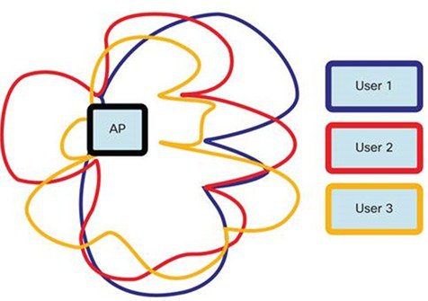
For all this to work properly, especially the deep nulls, the AP has to know the wireless channel from itself to all of the users very accurately. Because the channel changes over time, the AP has to keep measuring the channel, which adds overhead.
Meanwhile, the client receives its desired signal distorted by some interference from the signals intended for other users. This interference makes the highest constellations such as 256QAM infeasible within an MU-MIMO transmission.
In summary, MU-MIMO allows an AP to deliver appreciably more data to its associated clients, especially for small form-factor clients (often BYOD clients) that are limited to a single antenna. If the AP transmits to two or three clients, the effective speed increase varies from a factor of unity (no speed increase) up to a factor of two or three times, according to wireless channel conditions.
You cannot configure to use MU-MIMO, the clients will advertise this capability and the AP will put them into groups.
Elements of Multi-User MIMO
-
802.11ac MU-MIMO is similar to traditional 802.11n MIMO, except instead of one client at a time, it supports up to several clients that can all receive different data simultaneously.
-
AP does pre-coding for all the clients; basically aggregating clients that advertise MU-MIMO capability into groups that participate in MU-MIMO process.
-
It is an elaborate process. In MU pre-coding, when the AP is beamforming the signal, for example at 1SS or 2SS rate to a particular client, the space-time streams have to be constructed so that it also simultaneously null-steers to those space-time streams being sent to the other clients.
-
All users’ MPDUs are padded to the same number of OFDM symbols. The AP seeks out opportunities to send similar size packets out to the MU-MIMO clients to optimize on air time increasing throughput by sending data out to 2 – 4 clients per transmission. The number of clients depends on the type of stream, for example one client can receive 1SS while another is receiving 2SS.
-
Wi-Fi alliance certification for Wave-2 includes MU-MIMO.
-
Take-away: MU-MIMO is designed to maximize downlink capacity by overlapping clients in space (multiplexing). Best performance occurs with high client counts and high AP densities.
Challenges of Multi-User MIMO
-
Requires precise (CSI) channel state information to maintain deep nulls so that each MU-MIMO client can properly decode its data without too much interference from the other clients.
-
MU-MIMO CSI, pre-coding group data adds overhead as does their acknowledgments and so on.
-
Rate adaptation is slow – Wave-2 clients to be integrated into new laptops, tablets, and phones but this moves slowly.
-
MU-MIMO is a new technology and needs to develop and mature. So, issues such as lower end clients may be sensitive to MU grouping overhead and client driver version issues.
Checking the Access Point LEDs
Access Point Status LEDs
Note |
Regarding LED status colors, it is expected that there will be small variations in color intensity and hue from unit to unit. This is within the normal range of the LED manufacturer’s specifications and is not a defect. |
The access point status LED indicates various conditions and are described in Table 1.
|
Message Type |
Status LED |
Message Meaning |
|---|---|---|
|
Boot loader status sequence |
Blinking green |
DRAM memory test in progress |
|
DRAM memory test OK |
||
|
Board initialization in progress |
||
|
Initializing FLASH file system |
||
|
FLASH memory test OK |
||
|
Initializing Ethernet |
||
|
Ethernet OK |
||
|
Starting operating system |
||
|
Initialization successful |
||
|
Association status |
Chirping Green |
Normal operating condition, but no wireless client associated |
|
Green |
Normal operating condition, at least one wireless client association |
|
|
Operating status |
Blinking amber |
Software upgrade in progress |
|
Cycling through green, red, and amber |
Discovery/join process in progress |
|
|
Rapidly cycling through red, green, amber, and off. |
Access point location command invoked |
|
|
Blinking red |
Ethernet link not operational |
|
|
Boot loader warnings |
Blinking amber |
Configuration recovery in progress (MODE button pushed for 2 to 3 seconds) |
|
Red |
Ethernet failure or image recovery (MODE button pushed for 20 to 30 seconds) |
|
|
Blinking green |
Image recovery in progress (MODE button released) |
|
|
Boot loader errors |
Red |
DRAM memory test failure |
|
Blinking red and amber |
FLASH file system failure |
|
|
Blinking red and off |
Environment variable failure |
|
|
Bad MAC address |
||
|
Ethernet failure during image recovery |
||
|
Boot environment failure |
||
|
No Cisco image file |
||
|
Boot failure |
||
|
Cisco IOS errors |
Red |
Software failure; try disconnecting and reconnecting unit power |
|
Cycling through red, green, amber, and off |
General warning; insufficient inline power |
Ethernet Port LEDs
Each Ethernet port has two LEDs for showing Link (Green) and Activity (Amber) statuses. They are integrated on the RJ45 connector. For a description of the statuses they indicate, see the following table.
|
LED |
10M Link |
10M Active |
100M Link |
100M Active |
1000M Link |
1000M Active |
|---|---|---|---|---|---|---|
|
Link (Green) |
Off |
Off |
Off |
Off |
On |
On |
|
Activity (Amber) |
On |
Blinking |
On |
Blinking |
On |
Blinking |
Q & A
- Q: Cisco has a newer Power Injector (AIR-PWR-INJ5). Can I use this with the AP 1850?
-
A: The newer AIR-PWR-INJ5 is a low cost injector for use with the AP 1600 and AP 2600 series products. It is an 802.3af (15.4 W injector) and will power the AP 1850 at reduced functionality. It is recommended to use AIR-PWR-INJ4, which is a 30 W injector, as the AP 1850 draws roughly 20 W for full functionality.
- Q: Can industrial wireless motion or smoke detectors cause WLAN interference?
-
A: Yes, some products such as United Technologies DD475 and Optex MX-50 operate in the 2.4 GHz band as do other wireless chimes, cameras, and other industrial equipment from other manufacturers.
- Q: What if I am in a country where the regulatory agency may not approve the AP to be used outdoors because of UNII-1 band restrictions or if I wish to use higher gain antennas?
-
A: Consider deploying the Cisco Mesh products (1570, 1550, and 1530 series) or look for access points ending in “P” for professional install, such as the 3602P and 3702P series.
- Q: Any other thoughts when installing wireless APs?
-
A: When installing wireless APs, consider the following:
-
Place the APs as reasonably close to the actual users as possible.
-
Make sure that you have coverage (to a known requirement) and compensate for nulls or dead spots regardless of what product you choose to deploy. This is called a site survey.
-
Installations should be done based on lessons learned from the site survey. The better the survey the less likely any connectivity problems will occur.
-
Cisco has an advanced services team that can perform WLAN surveys or help with the wireless design if a partner is not available or able to do the same.
-
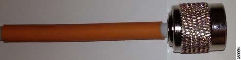
When possible, use Cisco brand antennas listed in this document (with the orange band).
-
Do not mount antennas against metal objects. Similar to a light bulb, antennas work best when there are no obstructions in the path.
-
AP 1600, 1700, 1850, 2600, 2700, 3600, and 3700 are not weatherproof and have an IP rating of 40.
-
- Q: Why am I seeing 6.x.x.x address in CDP Neighbour table on Cisco 1832/1852 AP?
-
A: The 1830 and 1850 access points have a default IP address, in the form 6.x.x.x, which they revert to if they do not receive an IP address through DHCP. You can see this IP address when you use the command show cdp neighbor from the connected switch. This IP address will exist until any DHCP issues in the network are resolved and the APs are assigned an IP address via DHCP.
References
AP 1850 Product Page and Datasheet
http://www.cisco.com/go/ap1850
AP 3700 Datasheet
http://www.cisco.com/en/US/prod/collateral/wireless/ps5678/ps13367/data_sheet_c78-729421.html
AP and Controller Datasheets
http://www.cisco.com/en/US/products/hw/wireless/index.html
Cisco Antenna Reference Guide
Why Buy Cisco Brand Antennas
http://www.cisco.com/en/US/prod/collateral/wireless/ps5678/ps10981/white_paper_c11-671769.pdf
Understanding Antenna Patterns and their Meaning
Cisco Guest Access Deployment Guide
Cisco Schools WLAN Deployment Guide
http://www.cisco.com/en/US/docs/solutions/Verticals/Education/SRA_Schools/schoolSRA_wlan_sba.pdf
The Apple Bonjour/Apple TV Deployment Guide
Optimizing Enterprise Video over Wireless LAN
Cisco 7925 IP Phone Deployment Guide
http://www.cisco.com/en/US/docs/voice_ip_comm/cuipph/7925g/7_0/english/deployment/guide/7925dply.pdf
Cisco Mobility Services Engine – WLAN Location Deployment Guide
http://www.cisco.com/en/US/products/ps9742/products_tech_note09186a00809d1529.shtml
WLAN Design Guide for High Density Client Environments in Higher Education
http://www.cisco.com/en/US/prod/collateral/wireless/ps5678/ps10981/design_guide_c07-693245.pdf
Mobility Design Guides
http://www.cisco.com/en/US/netsol/ns820/networking_solutions_program_home.html
Software Support and Downloads
New Generation of Cisco Aironet Access Points
http://www.cisco.com/en/US/prod/collateral/wireless/ps5678/ps10981/at_a_glance_c45-636090.pdf
802.11ac Customer Use Cases
http://www.cisco.com/en/US/prod/collateral/wireless/ps5678/ps13367/at_a_glance_c45-729588.pdf
Adaptive Radio Modules
http://www.cisco.com/en/US/prod/collateral/wireless/ps5678/ps11983/at_a_glance_c45-727334.pdf
New Generation of Cisco Aironet Access Points
http://www.cisco.com/en/US/prod/collateral/wireless/ps5678/ps10981/at_a_glance_c45-636090.pdf
802.11ac Wave-1 Module Datasheet
http://www.cisco.com/en/US/prod/collateral/modules/ps12859/ps13128/data_sheet_c78-727794.html
802.11ac – The Fifth Generation Wi-Fi Technical Whitepaper
 Feedback