Product Overview
The explosion of mobile clients in enterprise empowered by bring your own device (BYOD), the deployment of wireless in mission-critical applications, and the adoption of Wi-Fi in service provider networks enabling new business models require wireless networks to provide larger AP scale, client scale, and higher throughput.
The Cisco 3504 Wireless Controller is a compact, highly scalable, service-rich, resilient, and industry's first Multigigabit Ethernet platform that enables next-generation wireless networks for small to medium-sized enterprises and branch office deployments.
Optimized for for 802.11ac Wave 2 performance, Cisco 3504 Wireless Controller provides centralized control, management, and troubleshooting for small to medium-sized enterprises and branch offices. It offers flexibility to support multiple deployment modes in the same controller-a centralized mode for campus environments, Cisco FlexConnect® mode for lean branches managed over the WAN, and a mesh (bridge) mode for deployments in which full Ethernet cabling is unavailable.
As a component of the Cisco Unified Wireless Network, the 3504 controller provides real-time communications between Cisco Aironet® Access Points, Cisco Prime® Infrastructure, and Cisco Mobility Services Engine, and is interoperable with the Cisco 5520 and 8540 Wireless Controllers.
Cisco WLC 3504 Key Attributes
The Cisco Unified Wireless Network Software Release 8.5 delivers the new Cisco WLC 3504 controller with support for 150 APs, 3,000 and 4 Gbps throughput, to ensure better performance and scale for business-critical networks.
| Features | Benefit |
|---|---|
| Scale and Performance | Optimized to enable 802.11ac Wave 2 next-generation networks,
supporting:
|
| Redundancy and High Availability |
|
| AP Mode Support |
|
| AP Platform Support |
|
| Security |
|
| Ease of Deployment |
|
| Licensing |
|
 Note |
Cisco WLC 3504 has software feature parity with Cisco WLC 5520 unless otherwise stated. |
Supported Software Release and Interoperability
-
AireOS® Release –AireOS® Release 8.5.103.0 and later
-
Cisco Prime Infrastructure–Release 3.2
-
Identity Services Engine–Recommended ISE Release 2.2 and later
-
Connected Mobility Experiences (CMX)–10.2 and later
Platform Components
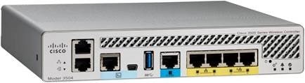
Understanding Cisco WLC 3504 Front Panel View
| Interfaces on WLC 3504 | Port as noted in figure above | Description |
|---|---|---|
| Service Port | 1 | Dedicated Service Port for Out-of-Band Management |
| Console | 2 and 3 | There are two console ports on the WLC 3504. There is a serial RJ45 console port and a mini USB port. Both of these console ports are in XOR configuration i.e. only one will be operational at a time. If one connects to both the console ports, RJ45 will take precedence. |
| USB | 4 | USB 3.0 Port can be used to perform Software Updates in addition to already available Transfer Mode i.e. HTTP, TFTP, FTP and SFTP. |
| mGig Port | 5 | There is one mGig port for Data Connectivity which can be configured for 1, 2.5 and 5 Gbps |
| GiGE Ports | There are four Gigabit Ethernet Ports on the WLC 3504 for Data Connectivity. Port 3 and Port 4 also have PoE out and can provide 802.3at power. | |
| Reset | 7 | Reset button can be used to Reset the WLC 3504 to factory defaults. |
| Status LED | 8 | There are three LEDs on the front panel of WLC3504. There is a System LED, Alarm LED and High Availability LED. For description of LED states, please refer to the section LED Indicators. |
| Redundancy Port | 9 | WLC 3504 supports High Availability similar to WLC 5520 and WLC 8540. The Redundancy ports can be connected back to back or via an L2 switch. |
LED Status Indicators
There are 3 LEDs on the front panel of WLC 3504. They are as follows:
-
System LED
-
Alarm LED
-
High Availability LED

| LED Indicators | Icons as noted in figure above |
|---|---|
| System | 1 |
| Alarm | 2 |
| High Availability | 3 |
For LED state definitions, please refer to the tables below:
| Function | System LED State | |
| Green | Amber | |
| System Power Up | OFF | BLINKS |
| System boot | BLINKS | OFF |
| After boot up | ON | OFF |
| Controller image upgrade | ON | OFF |
| System Crash | OFF | ON |
| Firmware Upgrade | OFF | ON |
| Internal Voltage Error | OFF | BLINKS |
| Temperature Error | OFF | OFF |
| Function | Alarm LED State | |
| Green | Amber | |
| System Power Up | OFF | ON |
| System boot | OFF | ON |
| After boot up | OFF | OFF |
| Controller image upgrade | BLINKS | OFF |
| System Crash | OFF | OFF |
| Firmware Upgrade | OFF | ON |
| Internal Voltage Error | OFF | ON |
| Temperature Error | OFF | BLINKS |
| Function | High Availability LED State |
| HA Port paired with peer controller | SOLID GREEN |
| HA StandBy HOT | SLOW BLINK GREEN |
| Bootup and HA Standby Cold | SLOW BLINK AMBER |
| HA Maintenance | FAST BLINK AMBER |
| Peer not found | SLOD AMBER |
| Standby/HA Disabled | OFF |
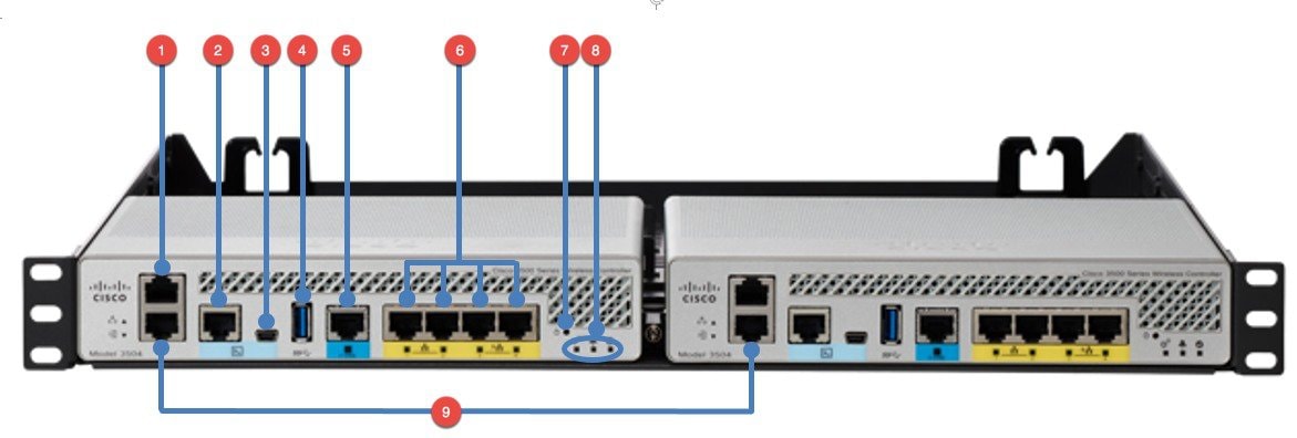
Understanding Cisco WLC 3504 Back Panel View
Similar to the WLC 2504, the power connector on WLC 3504 is at the back of the chassis. It is a 4 Pin locking Molex MiniFit Jr. jack. There is also a Kensington Security Port is the WLC chassis has to be locked down.
| Interfaces on WLC 3504 | Port as noted in figure above | Description |
| Power Port | 1 | 4 Pin locking Molex MiniFit Jr Jack |
| Heat Fins | 2 | Heat Fins |
| Security Port | 3 | Kensington Security Port |
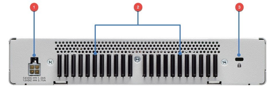
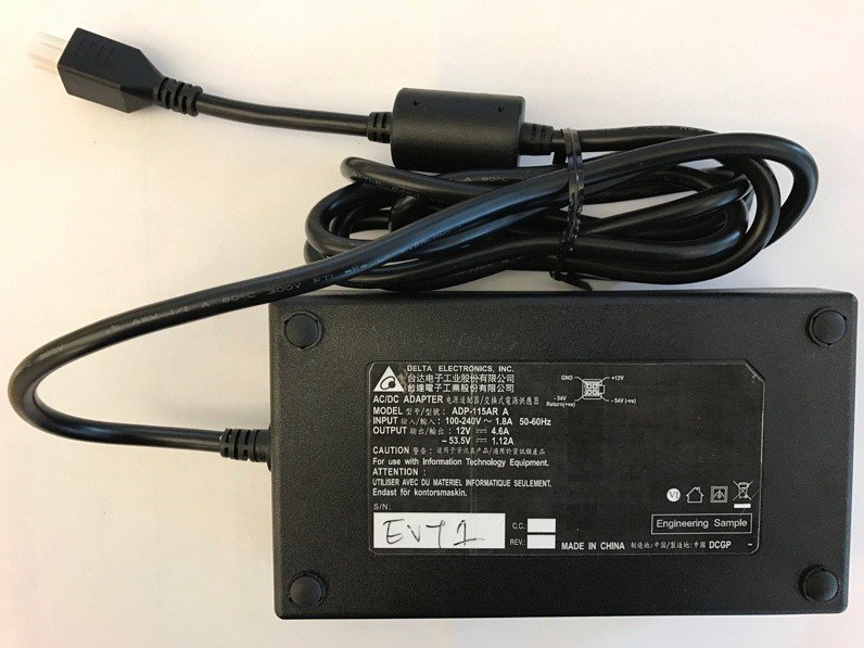
WLC 3504 Power Supply
Deploying Cisco WLC 3504
Cisco WLC 3504 supports deploying WLC 3504 using the Service Port as well as CLI. In this guide, both of the methods are documented below.
Note |
Over-the-air-provisioning is not supported on WLC 3504 in Release 8.5. |
Deploying WLC 3504 through Service Port
Service Port on Cisco WLC 3504 supports the following management services:
-
HTTP/HTTPS web-based access
-
SNMP polling v2 and v3
-
Syslog
-
SSH or Telnet
-
Transfer download and upload
To deploy WLC 3504 using the Service Port, follow the procedure below:
Procedure
| Step 1 |
Connect a PC laptop's wired Ethernet port directly to Service Port of the WLC 3504. |
| Step 2 |
Power up WLC 3504. |
| Step 3 |
The Laptop should get an IP address in 192.168.0.x network. |
| Step 4 |
Open the browser and browse to http://192.168.0.1 . The Setup Wizard will start. |
| Step 5 |
Create the WLC admin account as shown below. 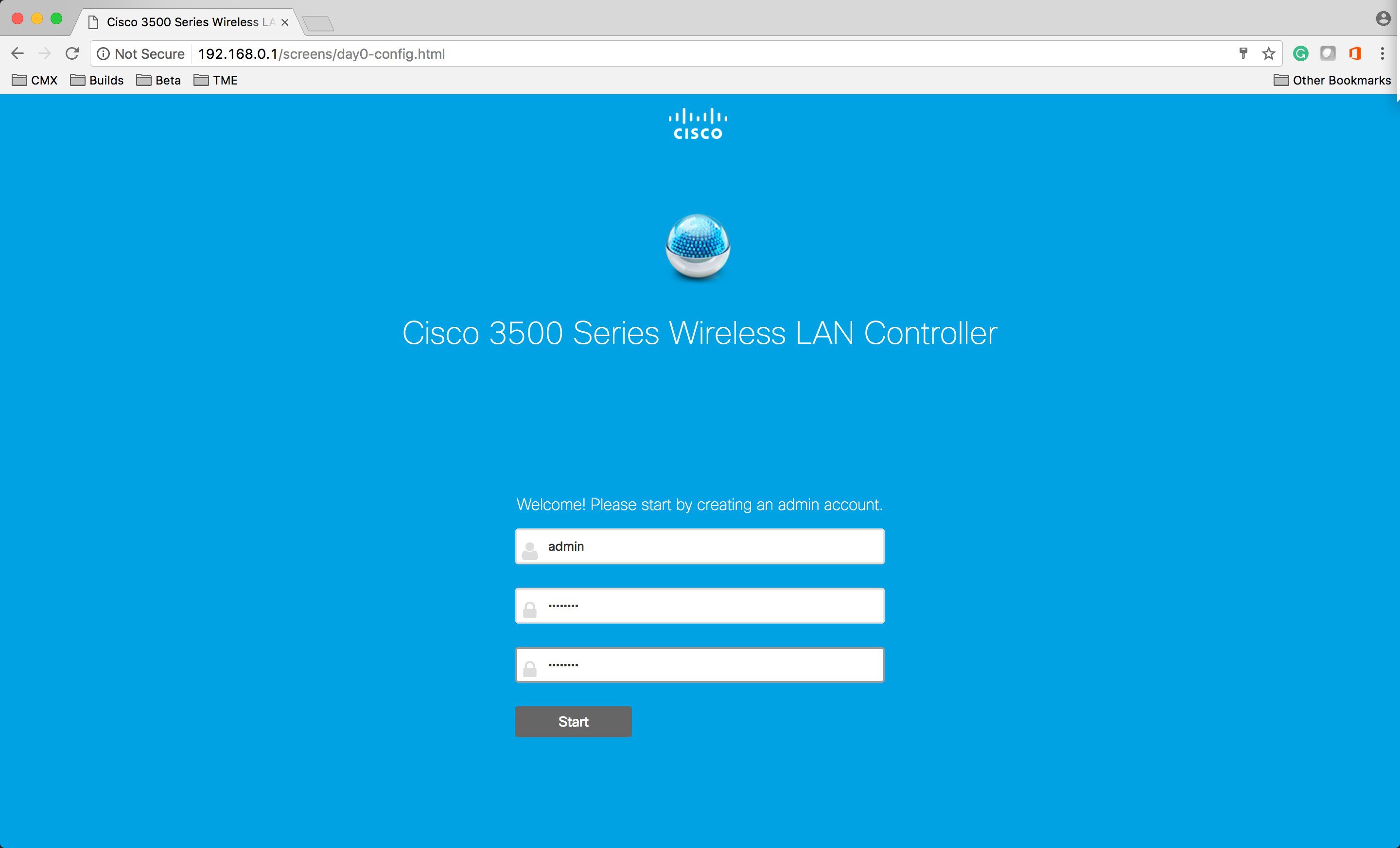 |
| Step 6 |
Under the Set Up Your Controller section, please enter the following:
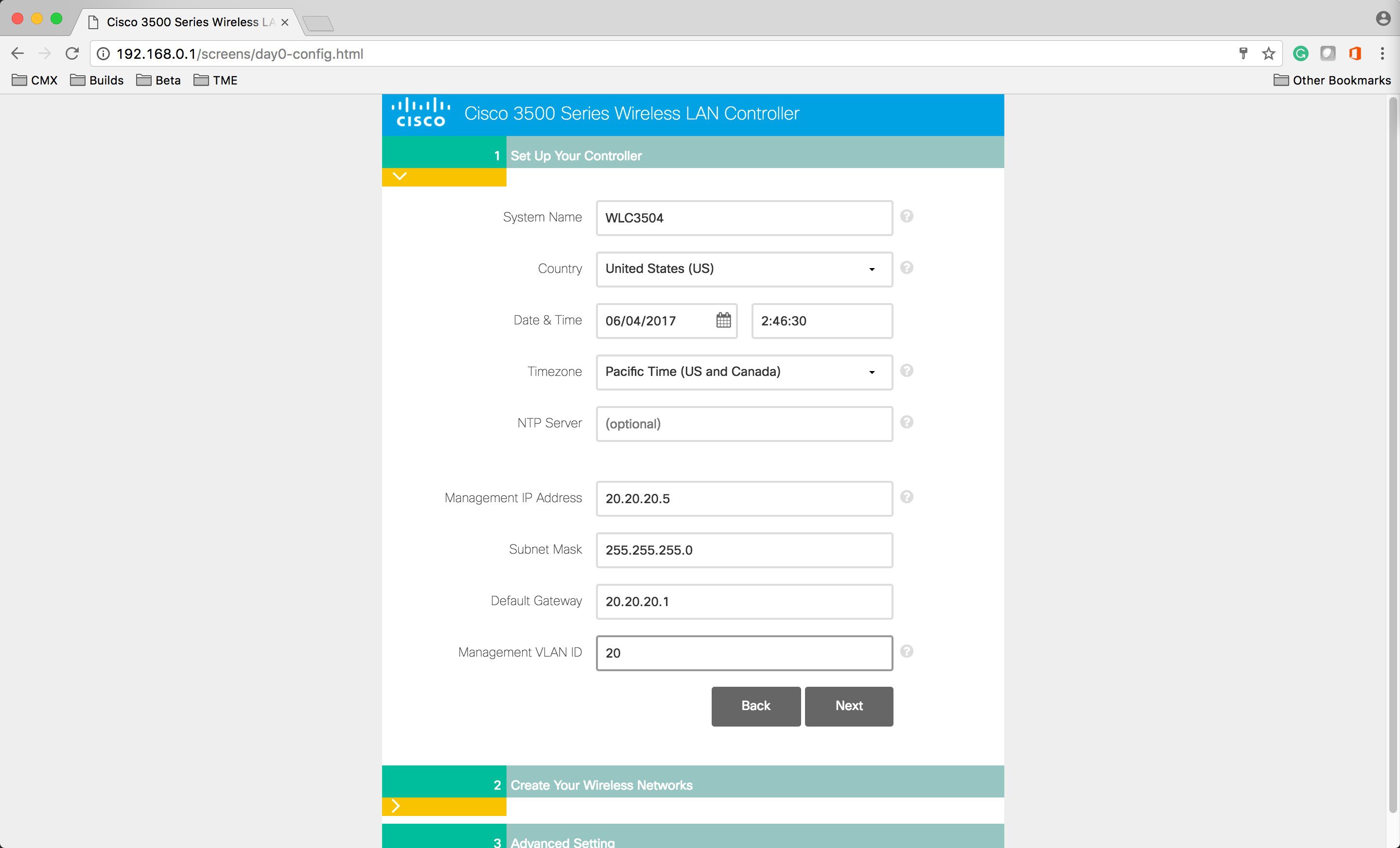 |
| Step 7 |
Under the Create Your Wireless Network, enter the following:
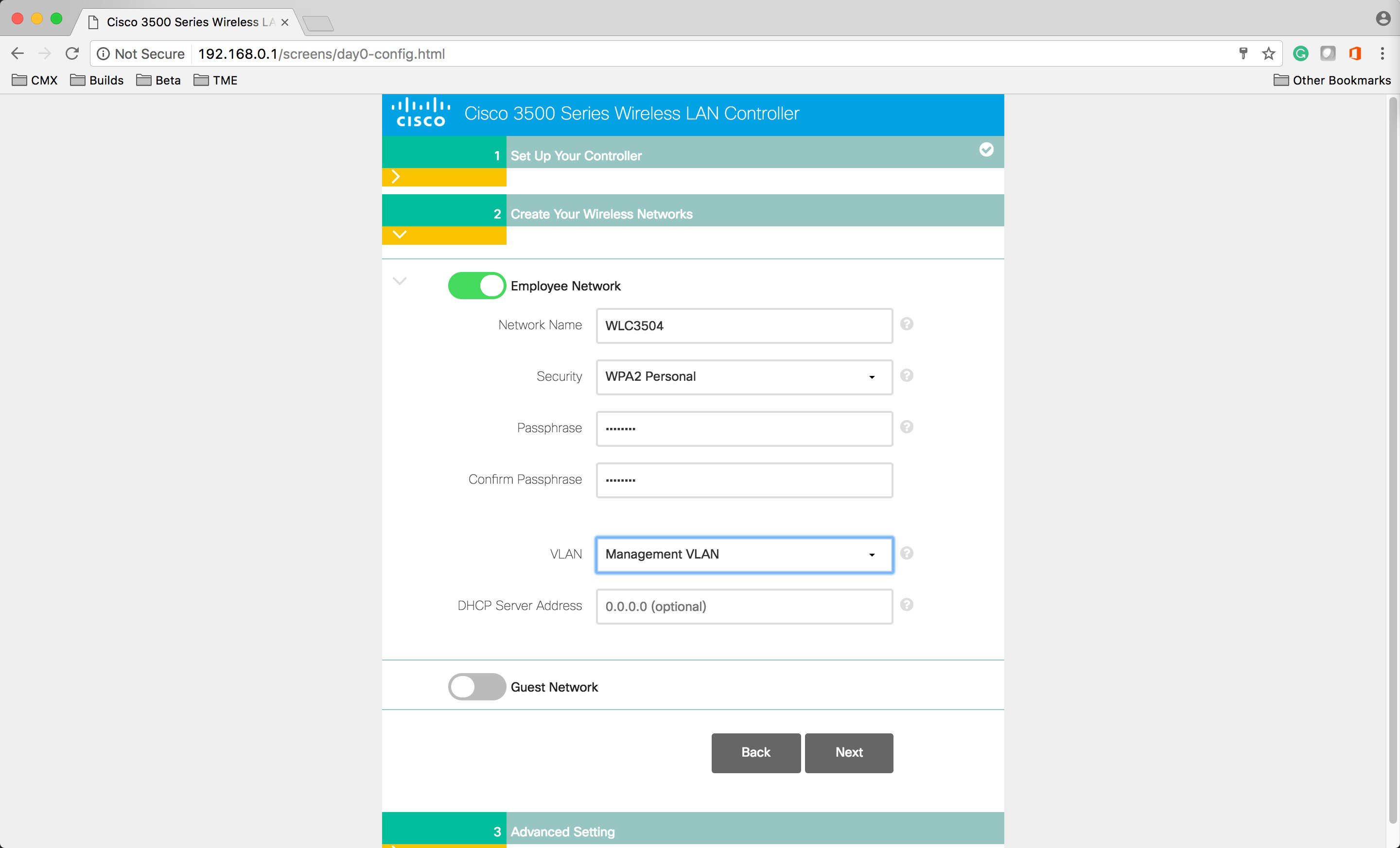 |
| Step 8 |
Enable RF Parameter Optimization and select the Client Density and Traffic Type. |
| Step 9 |
Enter the following as well:
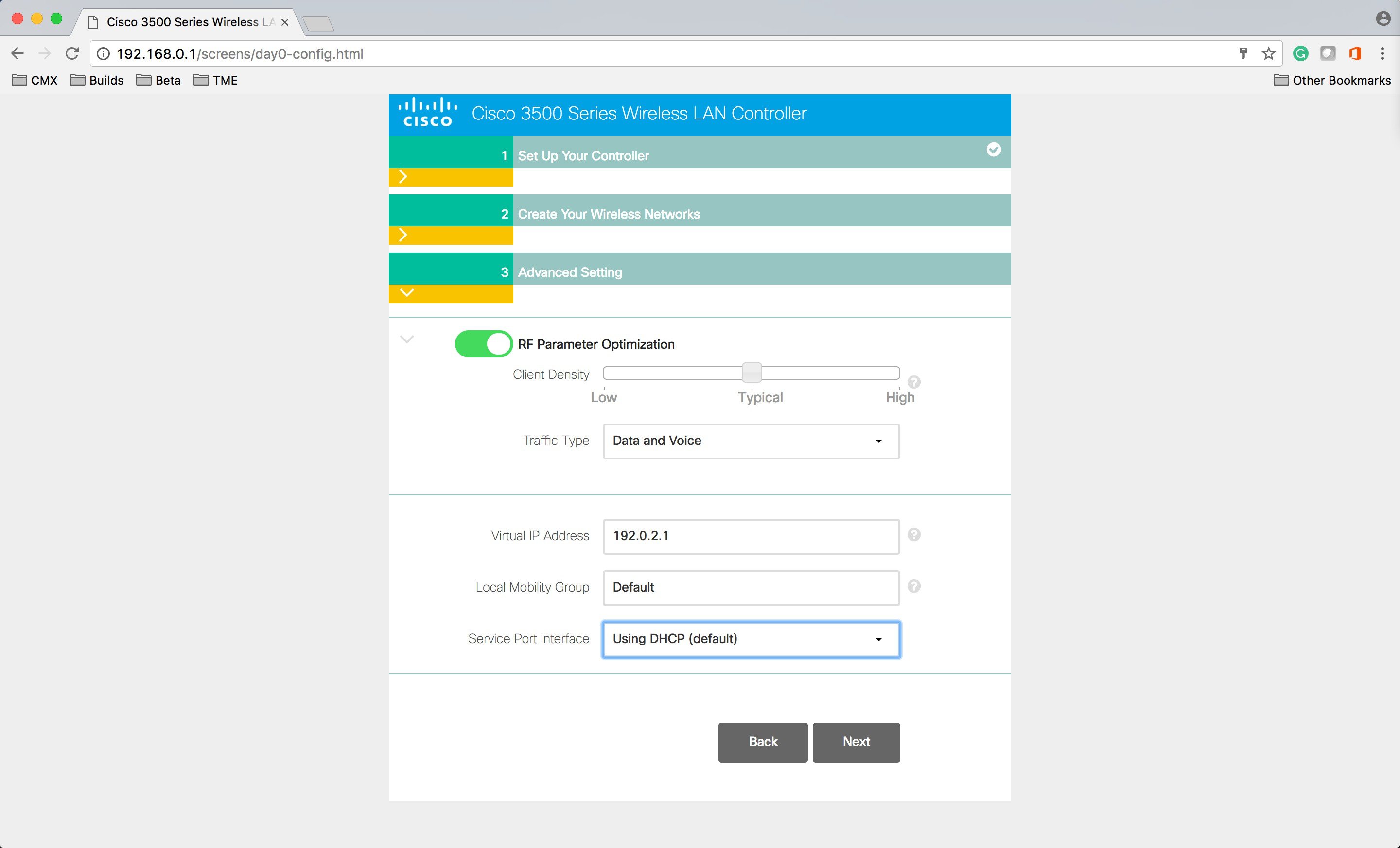 |
| Step 10 |
Confirm the Settings below. The WLC will go through the reboot. 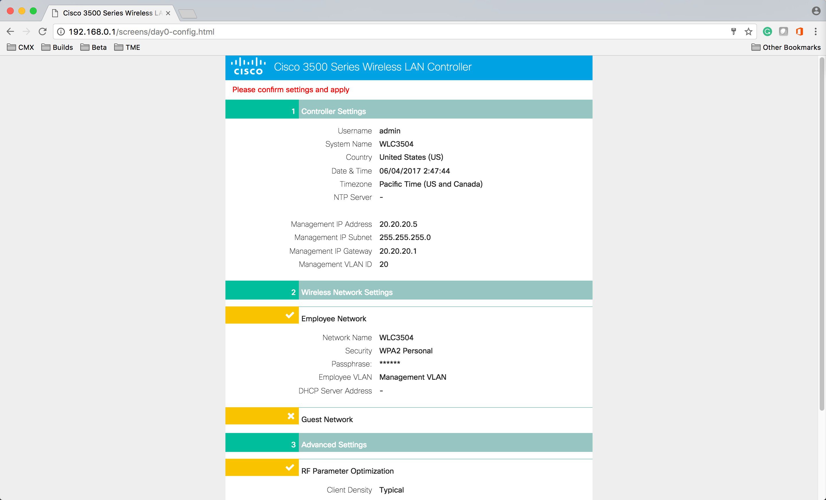 |
| Step 11 |
After the reboot, open a Web Browser and navigate to the WLC 3540 Management WebUI. |
Deploying WLC 3504 through CLI
Deploying WLC 3504 is similar to how the 5508 and 5520 WLC are deployed.
To deploy WLC 3504, follow the procedure below:
Procedure
| Step 1 |
Connect to the console of the WLC 3504. |
| Step 2 |
|
High Availability with Cisco WLC 3504
High Availability is for box-to-box redundancy. In other words, 1:1 where one WLC will be in an Active state and the second WLC will be in a Hot Standby state continuously monitoring the health of the Active WLC via a Redundant Port. Both the WLCs will share the same set of configurations including the IP address of the Management interface. The WLC in the Standby state does not need to be configured independently as the entire configuration (Bulk Configuration while boot up and Incremental Configuration in runtime) will be synced from the Active WLC to the Standby WLC via a Redundant Port. The AP's CAPWAP State (only APs which are in a run state) is also synced, and a mirror copy of the AP database is maintained on the Standby WLC. The APs do not go into the Discovery state when the Active WLC fails and the Standby WLC takes over the network's Active WLC.
There is no preempt functionality. When the previous Active WLC comes back, it will not take the role of the Active WLC, but will negotiate its state with the current Active WLC and transition to a Standby state.
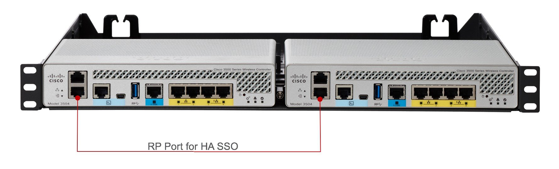
Note |
One can also connect RP port through a L2 switch. |
WLC supports the same HA configuration as other WLC. To configure High Availability, refer to the HA deployment guide at the link below: http://www.cisco.com/c/en/us/td/docs/wireless/controller/technotes/8-1/HA_SSO_DG/High_Availability_DG.html
Configuring mGig Port on WLC 3504
WLC 3504 has a 1x mGig and 4x GE ports. Please note the following about the ports:
-
mGIg port is displayed as Port 5 on the WLC UI.
-
mGig port and 4x GE ports can be used for switch connectivity.
-
Only 4x GE ports can be used for direct AP connectivity
-
mGig port can be configured for 1G, 2.5G, and 5G.
-
If mGig is enabled for 5G, 4x GE ports will be set to 100 Mbps.
-
If mGig is enabled for 2.5G, GE1 and GE2 will stay at 1G and GE3 and GE4 will be set to 100 Mbps.
-
If mGig is configured for 1G, GE1, GE2, GE3 and GE4 will be set to 1Gbps.
To change the speed on the mGig port, follow the procedure below:
Procedure
| Step 1 |
Navigate the WLC WebUI and browse to Controller > Ports. Click on Port 5. 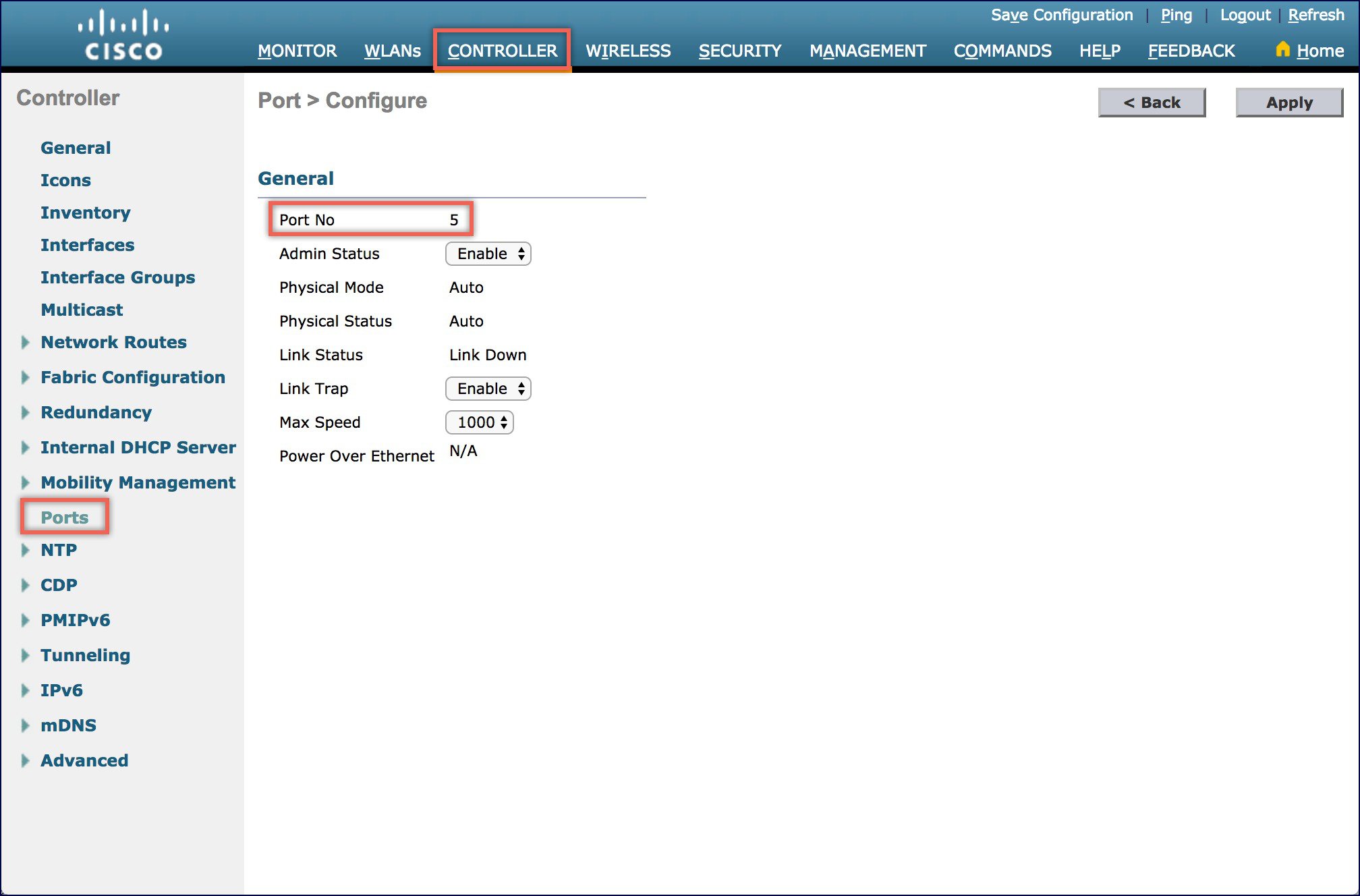 |
| Step 2 |
Set the Max Speed to either 1000, 2550 or 5000. Please note that If the speed is set to 2500 or 5000 on mGIg port, it will negotiate with the corresponding switch port for the max speed it can support. |
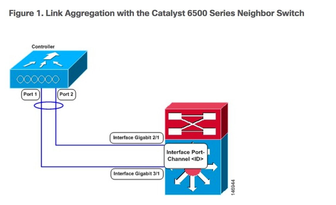
Configuring LAG between WLC and Switch
Link aggregation (LAG) is a partial implementation of the 802.3ad port aggregation standard. It bundles all of the controller's distribution system ports into a single 802.3ad port channel, thereby reducing the number of IP addresses needed to configure the ports on your controller. When LAG is enabled, the system dynamically manages port redundancy and load balances access points transparently to the user.
LAG simplifies controller configuration because you no longer need to configure primary and secondary ports for each interface. If any of the controller ports fail, traffic is automatically migrated to one of the other ports. As long as at least one controller port is functioning, the system continues to operate, access points remain connected to the network, and wireless clients continue to send and receive data.
Note |
Cisco WLC does not send CDP advertisements on a LAG interface. |
Restrictions for Link Aggregation
-
You can bundle all 5 ports on a Cisco WLC 3504 into a single link.
-
When you include mGig port on the WLC 3504 in LAG, it must be configured to 1Ggig.
-
LAG requires the EtherChannel to be configured for 'mode on' on both the controller and the Catalyst switch.
-
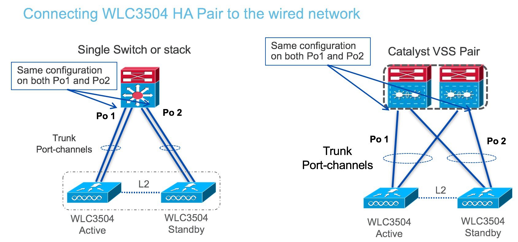
Terminating on two different modules within a single Catalyst 6500 series switch provides redundancy and ensures that connectivity between the switch and the controller is maintained when one module fails. The controller’s port 1 is connected to Gigabit interface 3/1, and the controller’s port 2 is connected to Gigabit interface 2/1 on the Catalyst 6500 series switch. Both switch ports are assigned to the same channel group.
-
Once the EtherChannel is configured as on at both ends of the link, the Catalyst switch should not be configured for either Link Aggregation Control Protocol (LACP) or Cisco proprietary Port Aggregation Protocol (PAgP) but be set unconditionally to LAG. Because no channel negotiation is done between the controller and the switch, the controller does not answer to negotiation frames and the LAG is not formed if a dynamic form of LAG is set on the switch. Additionally, LACP and PAgP are not supported on the controller.
-
If the recommended load-balancing method cannot be configured on the Catalyst switch, then configure the LAG connection as a single member link or disable LAG on the controller.
-
You cannot configure the controller’s ports into separate LAG groups. Only one LAG group is supported per controller. Therefore, you can connect a controller in LAG mode to only one neighbor device.
-
When you enable LAG or make any changes to the LAG configuration, you must immediately reboot the controller.
-
When you enable LAG, you can configure only one AP-manager interface because only one logical port is needed. LAG removes the requirement for supporting multiple AP-manager interfaces.
-
When you enable LAG, all dynamic AP-manager interfaces and untagged interfaces are deleted, and all WLANs are disabled and mapped to the management interface. Also, the management, static AP-manager, and VLAN-tagged dynamic interfaces are moved to the LAG port.
-
Multiple untagged interfaces to the same port are not allowed.
-
When you enable LAG, you cannot create interfaces with a primary port other than 29.
-
When you enable LAG, access points remain connected to the controller until you reboot the controller, which is needed to activate the LAG mode change, and data service for users continues uninterrupted.
-
When you enable LAG, the controller sends packets out on the same port on which it received them. If a CAPWAP packet from an access point enters the controller on physical port 1, the controller removes the CAPWAP wrapper, processes the packet, and forwards it to the network on physical port 1. This may not be the case if you disable LAG.
-
When you disable LAG, the management, static AP-manager, and dynamic interfaces are moved to port 1.
-
When you disable LAG, you must assign an AP-manager interface to each port on the controller. Otherwise, access points are unable to join.
Configuring LAG on WLC
To configure LAG, follows the procedure below:
Procedure
| Step 1 |
Choose Controller > General to open the General page. |
| Step 2 |
Set the LAG Mode on Next Reboot parameter to Enabled. |
| Step 3 |
Save the configuration. |
| Step 4 |
Reboot Cisco WLC. |
| Step 5 |
Assign the WLAN to the appropriate VLAN. |
Configuring Neighbor Devices to Support Link Aggregation
The controller's neighbor devices must also be properly configured to support LAG.
Each neighbor port to which the controller is connected should be configured as follows:
interface GigabitEthernet <interface id>
 switchport
 channel-group <id> mode on
 no shutdown
interface port-channel <id>
 switchport
 switchport trunk encapsulation dot1q
 switchport trunk native vlan <native vlan id>
 switchport trunk allowed vlan <allowed vlans>
 switchport mode trunk
 no shutdown
Upgrading WLC 3504 using USB
Upgrading via USB is a new Transfer Mode which is available on Cisco WLC 3504. To upgrade via USB, follow the procedure below:
Procedure
| Step 1 |
Download the WLC3504 Software Image on the USB and insert the USB interface on the front panel of WLC 3504. |
| Step 2 |
Login to the WLC CLI and execute the following command: |
| Step 3 |
Login to the WLC WebUi and navigate to the COMMANDS menu as shown below.
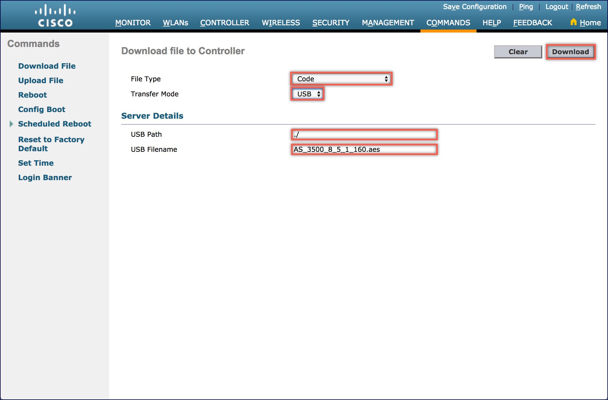 |
| Step 4 |
Click on the Download button to initiate the software download and click on OK when you see the confirmation window. |
| Step 5 |
After the Software Download is complete, please reboot the WLC to run the new software. Shown below is the debug messages in the WLC CLI while performing Software Download from USB. |
 Feedback