- Cisco Unified Wireless Network Solution Overview
- Cisco Unified Wireless Technology and Architecture
- WLAN RF Design Considerations
- Cisco Unified Wireless Network Architecture—Base Security Features
- Cisco Unified Wireless QoS and AVC
- Cisco Unified Wireless Multicast Design
- FlexConnect
- Cisco Wireless Mesh Networking
- VoWLAN Design Recommendations
- Cisco Unified Wireless Network Guest Access Services
- 802.11r, 802.11k, 802.11v, 802.11w Fast Transition Roaming
Enterprise Mobility 8.1 Design Guide
Bias-Free Language
The documentation set for this product strives to use bias-free language. For the purposes of this documentation set, bias-free is defined as language that does not imply discrimination based on age, disability, gender, racial identity, ethnic identity, sexual orientation, socioeconomic status, and intersectionality. Exceptions may be present in the documentation due to language that is hardcoded in the user interfaces of the product software, language used based on RFP documentation, or language that is used by a referenced third-party product. Learn more about how Cisco is using Inclusive Language.
- Updated:
- October 26, 2015
Chapter: Cisco Unified Wireless Network Architecture—Base Security Features
- Enhanced WLAN Security Options
- ACL and Firewall Features
- Layer 2 Access Control Lists
- DNS-based Access Control Lists
- DHCP and ARP Protection
- Peer-to-Peer Blocking
- Wireless IDS
- Cisco Adaptive Wireless Intrusion Prevention System
- Deployment Considerations - Required Components
- Client Exclusion
- Managing Rogue Devices and Policies
- Rogue AP
- Management Frame Protection
- Management System Security Features
- Cisco TrustSec SXP
Cisco Unified Wireless Network Architecture—Base Security Features
The Cisco Unified Wireless Network solution provides end-to-end security of architecture and product security features to protect wireless local area network (WLAN) endpoints, the WLAN infrastructure, and client communications.
The Cisco Unified Wireless Network solution builds upon the base security features of the IEEE 802.11-2012 standard by enhancing radio frequency (RF) and network-based security features to ensure overall security.
Secure Wireless Topology
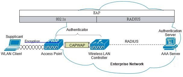
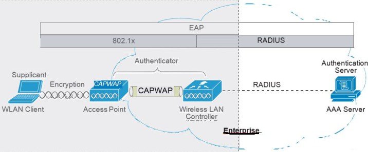
Figure 4-1 illustrates a secure wireless topology. The topology is made up of the following components with their basic roles in the 802.1X authentication process.
- WLAN client with 802.1X supplicant (wireless software) on the client.
- Access point (AP) and Wireless LAN Controller (WLC) using the control and provisioning of wireless access points (CAPWAP) protocol.
- RADIUS protocol carrying extensible authentication protocol (EAP) packets between the client and the authentication server.
- Authentication, Authorization, and Accounting (AAA) server as the Authentication Server.
Figure 4-1 Secure Wireless Topology
WLAN Security Mechanisms
Security is implemented using authentication and encryption in the WLAN network. The security mechanisms for WLAN networks are:
- Open Authentication (no encryption)
- Cisco WEP Extensions (Cisco Key Integrity Protocol + Cisco Message Integrity Check)
- Wi-Fi Protected Access (WPA)
- Wi-Fi Protected Access 2 (WPA2)
- Cisco Adaptive Wireless Intrusion Prevention System (wIPS) with Enhanced Local Mode (ELM)
Wi-Fi Protected Access (WPA)
The 802.11 WEP standard failed to address the issue of how to manage encryption keys. The encryption mechanism itself was found to be flawed, in that a WEP key could be derived simply by monitoring client traffic. The IEEE 802.11i standard addresses these security issues found in the original 802.11 WEP standard.
WPA and WPA2 are 802.11i-based security solutions as defined by the Wi-Fi Alliance. The Wi-Fi Alliance certifies inter-operability of IEEE 802.11 products and promotes wireless LAN standards across all market segments. The Wi-Fi Alliance's test suite defines how products are tested to obtain interoperability certification with other Wi-Fi Certified products.
WPA uses Temporal Key Integrity Protocol (TKIP) for encryption and dynamic encryption key generation with either a pre-shared key or a RADIUS/802.1x-based authentication. The mechanisms introduced in WPA are designed to provide more robust security to WEP solutions without requiring a hardware upgrade.
Wi-Fi Protected Access 2 (WPA2)
WPA2 is the next generation of Wi-Fi security based on the ratified IEEE 802.11i standard and is also approved by the Wi-Fi Alliance interoperability implementation of the 802.11i standard. WPA2 provides certification in both Enterprise and Personal classifications.
The Enterprise classification requires support for a RADIUS/802.1x-based authentication and pre-shared key; Personal classification requires only a common key shared by the client and the AP.
The newer Advanced Encryption Standard (AES) mechanism introduced in WPA2 generally requires a hardware upgrade of WLAN clients and APs; however, all Cisco CAPWAP hardware is WPA2 enabled.
802.1X
802.1X is an IEEE framework for port-based access control as adopted by the 802.11i security workgroup. The framework provides authenticated access to WLAN networks.
- The 802.11 association process creates a "virtual" port for each WLAN client at the AP.
- The AP blocks all data frames apart from 802.1X-based traffic.
- The 802.1X frames carry the EAP authentication packets, which are passed through to the AAA server by the AP.
- If the EAP authentication is successful, the AAA server sends an EAP success message to the AP, where the AP then allows data traffic from the WLAN client to pass through the virtual port.
- Before opening the virtual port, data link encryption is established between the WLAN client and the AP. This is to ensure no other WLAN client can access the port established for authenticating clients.
Authentication and Encryption
The Cisco Wireless Security suite provides options for security approaches based on required or pre-existing authentication, privacy, and client infrastructure. The Cisco Wireless Security suite supports WPA, WPA2, WEP Extension, and wIPS with the ELM feature.
The following options are available:
–![]() Cisco LEAP, EAP-Flexible Authentication via Secure Tunneling (EAP-FAST)
Cisco LEAP, EAP-Flexible Authentication via Secure Tunneling (EAP-FAST)
–![]() PEAP- Generic Token Card (PEAP-GTC)
PEAP- Generic Token Card (PEAP-GTC)
–![]() PEAP-Microsoft Challenge Authentication Protocol Version 2 (PEAP-MSCHAPv2)
PEAP-Microsoft Challenge Authentication Protocol Version 2 (PEAP-MSCHAPv2)
–![]() EAP-Transport Layer Security (EAP-TLS)
EAP-Transport Layer Security (EAP-TLS)
–![]() EAP-Subscriber Identity Module (EAP-SIM)
EAP-Subscriber Identity Module (EAP-SIM)
–![]() TKIP encryption enhancements: key hashing (per-packet keying), message integrity check (MIC) and broadcast key rotation via WPA/WPA2 or WEP TKIP Cisco Key Integrity Protocol (CKIP)
TKIP encryption enhancements: key hashing (per-packet keying), message integrity check (MIC) and broadcast key rotation via WPA/WPA2 or WEP TKIP Cisco Key Integrity Protocol (CKIP)
Extensible Authentication Protocol
Extensible Authentication Protocol (EAP) is an IETF RFC, stipulates that an authentication protocol must be de-coupled from the transport protocol. This allows the EAP protocol to be carried by transport protocols such as 802.1X, UDP, or RADIUS without making changes to the authentication protocol itself. The basic EAP protocol contains the following four packet types:
- EAP request—The request packet is sent by the authenticator to the supplicant. Each request has a type field that indicates what is being requested; for example, supplicant identity and EAP type to be used. A sequence number allows the authenticator and the peer to match an EAP response to each EAP request.
- EAP response—The response packet is sent by the supplicant to the authenticator, and uses a sequence number to match the initiating EAP request. The type of the EAP response generally matches the EAP request, except if the response is a negative-acknowledgment (NAK).
- EAP success—The success packet is sent, from the authenticator to the supplicant, when successful authentication occurs.
- EAP failure—The failure packet is sent, from the authenticator to the supplicant, when unsuccessful authentication occurs.
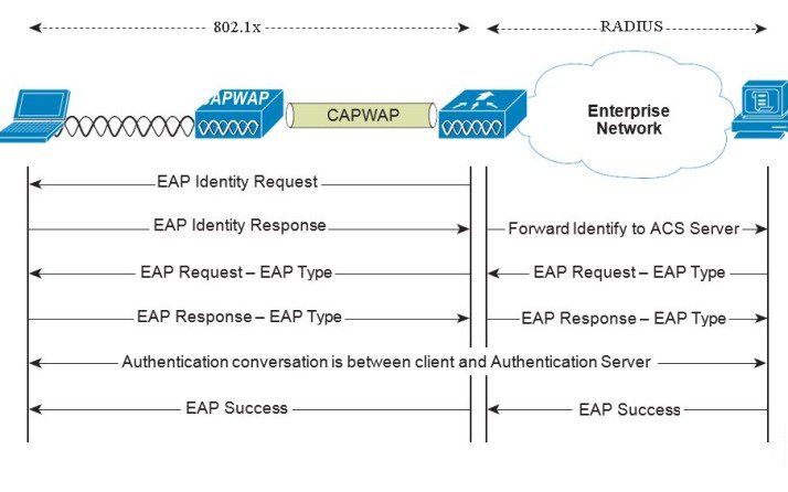
When using EAP in an 802.11i compliant system, the AP operates in EAP pass-through mode. Pass-through mode checks the code identifier and the length fields, and then forwards EAP packets received from the client supplicant to the AAA. EAP packets received by the authenticator from the AAA server are forwarded to the supplicant. Figure 4-2 is an example of an EAP protocol flow.
Authentication
Depending on your requirements, various authentication protocols such as PEAP, EAP-TLS, and EAP-FAST are used in secure wireless deployments. Regardless of the protocol, they all use 802.1X, EAP, and RADIUS as their underlying transport.
These protocols allow network access control based on the successful authentication of the WLAN client and vice-versa. This solution also provides authorization through policies communicated through the RADIUS protocol, as well as RADIUS accounting.
EAP types used for performing authentication are described in more detail below. The primary factor affecting the choice of EAP protocol is the authentication system (AAA) currently used. Ideally, a secure WLAN deployment should not require the introduction of a new authentication system, but rather should leverage the authentication systems that are already in place.
Supplicants
The various EAP supplicants that are available in the marketplace reflect the diversity of authentication solutions available and customer preferences.
Table 4-1 shows a summary of common EAP supplicants:
- EAP-FAST—EAP-Flexible Authentication via Secured Tunnel. Uses a tunnel similar to that used in PEAP, but does not require the use of Public Key Infrastructure (PKI).
- PEAP MSCHAPv2—Protected EAP MSCHAPv2. Uses a Transport Layer Security (TLS) tunnel, (the IETF standard of SSL) to protect an encapsulated MSCHAPv2 exchange between the WLAN client and the authentication server.
- PEAP GTC—Protected EAP Generic Token Card (GTC). Uses a TLS tunnel to protect a generic token card exchange; for example, a one-time password or LDAP authentication.
- EAP-TLS—EAP Transport Layer Security. Uses PKI to authenticate both the WLAN network and the WLAN client, requiring both a client certificate and an authentication server certificate.
|
|
|
|
|
|
|---|---|---|---|---|
Yes1 |
||||
Yes2 |
||||
Yes3 |
||||
Yes4 |
||||
Yes5 |
Yes6 |
|
2.Machine account and machine authentication is required to support the scripts. 3.Automatic provisioning is not supported on with LDAP databases. |
Authenticator
The WLC is the authenticator acting as a relay for EAP messages exchanged between the 802.1X-based supplicant and the RADIUS authentication server. Once authentication is completed successfully, the WLC receives the following:
- A RADIUS packet containing the EAP success message.
- An encryption key, which is generated at the authentication server during the EAP authentication.
- RADIUS vendor-specific attributes (VSAs) for communicating policy.
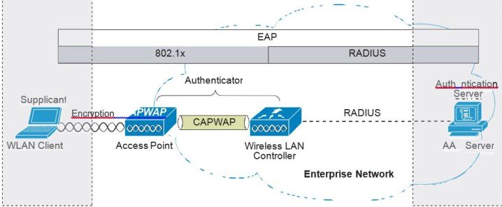
Figure 4-3 displays the logical location of the authenticator within the overall authentication architecture. The authenticator controls network access using the 802.1X protocol, and relays EAP messages between the supplicant and the authentication server.
Figure 4-3 Authenticator Location
The EAP exchange sequence is as follows:
- Packet no.1 is sent by the AP to the client, requesting the client identity; this begins the EAP exchange.
- Packet no.2 contains the client identity, which is forwarded to the RADIUS server. Based on the client identity, in packet 2, the RADIUS server will determine to continue the EAP authentication or not.
- Packet no.3 contains a RADIUS server request to use PEAP as the EAP method for authentication. The actual request depends on the EAP types configured on the RADIUS server. If the client rejects the PEAP request, the RADIUS server can offer other EAP types.
- Packets no.4 through 8 are the TLS tunnel setup for PEAP.
- Packets no.9 through 16 are the authentication exchange within PEAP.
- Packet no.17 is the EAP message informing the supplicant and the authenticator that the authentication was successful; in addition, Packet no.17 carries encryption keys and authorization information, in the form of RADIUS VSAs, to the authenticator.
Authentication Server
The authentication server used in the Cisco Secure Unified Wireless Network solution is the
Cisco Access Control Server (ACS) and the Cisco Identity Services Engine (ISE). ACS is available as software that is installed on a Windows 2000 or later servers, or as an appliance. ISE is available as software that is installed on the VM server. Alternatively, the authentication server role can be implemented within specific WLAN infrastructure devices such as local authentication services on an IOS AP, local EAP authentication support within the WLC, AAA services integrated in any AAA server that supports the required EAP types.
Figure 4-4 shows the logical location of the authentication server within the overall wireless authentication architecture, where it performs the EAP authentication via a RADIUS tunnel.
Figure 4-4 Authentication Server Location
After the completion of a successful EAP authentication, the authentication server sends an EAP success message to the authenticator. This message tells the authenticator that the EAP authentication process was successful, and passes the pair-wise master key (PMK) to the authenticator that is in turn used as the basis for creating the encrypted stream between the WLAN client and the AP.
Encryption
Encryption is a necessary component of WLAN security to provide privacy over a local RF broadcast network. Any new deployment should be using either TKIP (WPA/WPA2) or AES encryption.
In WPA and WPA2, the encryption keys are derived during the four-way handshake discussed later in this section.
TKIP Encryption
Enterprise-level encryption mechanisms specified by 802.11i are certified as WPA/WPA2 and wIPS by the Wi-Fi Alliance: Temporal Key Integrity Protocol (TKIP), and Advanced Encryption Standard (AES). TKIP is the certified encryption method. It provides support for legacy WLAN equipment by addressing the original flaws associated with the 802.11 WEP encryption method. It does this by making use of the original RC4 core encryption algorithm.
The hardware refresh cycle of WLAN client devices is such that TKIP and AES is likely to be a common encryption option for a number of years to come. The AES encryption is the preferred method because it brings the WLAN encryption standards into alignment with broader IT industry standards and best practices. Figure 4-5 displays a basic TKIP flow chart.
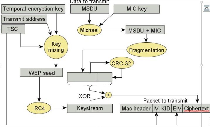
The two primary functions of TKIP are the generation of a per-packet key using RC4 encryption of the MAC service data unit (MSDU) and a message integrity check (MIC) in the encrypted packet. The per-packet key is a hash of the transmission address, the frame initialization vector (IV), and the encryption key. The IV changes with each frame transmission, so the key used for RC4 encryption is unique for each frame.
The MIC is generated using the Michael algorithm to combine a MIC key with user data. The use of the Michael algorithm is a trade-off because its low computational overhead is good for performance, but it can be susceptible to an active attack. To address this, WPA includes countermeasures to safeguard against these attacks that involve temporarily disconnecting the WLAN client and not allowing a new key negotiation for 60 seconds. Unfortunately, this behavior can itself become a type of DoS attack. Many WLAN implementations provide an option to disable this countermeasure feature.
Removal of TKIP from Wi-Fi® Devices
As per the Wi-Fi alliance and 802.11 WPA, wireless networks that use Temporal Key Integrity Protocol (TKIP), no longer provide sufficient security to protect consumer or enterprise Wi-Fi® networks. TKIP is an older security technology with known vulnerabilities to some cryptographic attacks.Wi-Fi® networks. TKIP is an older security technology with known vulnerabilities to some cryptographic attacks. TKIP and WEP use the same underlying cipher, and, consequently, they are vulnerable to a number of similar attacks. TKIP was designed as a transitional mechanism in 2004 for devices equipped with WEP and unable to support AES. Due to the known vulnerabilities of TKIP, networks utilizing it may be more susceptible to attack.
- Network administrators should purchase or deploy equipment that supports WPA2.
- Network administrators should configure their APs to be WPA2 only.
- Equipment vendors should proactively transition away from TKIP support by discouraging its use to their customer base, and removing the functionality in product as internal research indicates when their market no longer needs it.
For equipment vendors, Wi-Fi Alliance recommends that they discourage the use of TKIP in the short term, and ultimately remove TKIP from all Wi-Fi devices when their market no longer needs it. At a minimum, vendors should remove TKIP and any "TKIP-only" mode configurations from the primary device interface. Access to the "TKIP-only" configuration mode via a secondary configuration interface is acceptable. The requirement to go to a secondary interface is a mechanism used to restrict TKIP usage to only those deployments with legacy devices; other deployments will typically use the primary configuration interface.
Vendors should remove TKIP and any "TKIP-only" mode configurations from the primary device interface. Access to the "TKIP-only" configuration mode via a secondary configuration interface is acceptable (CLI).
For more information, see Technical Note - Removal of TKIP from Wi-Fi Devices.
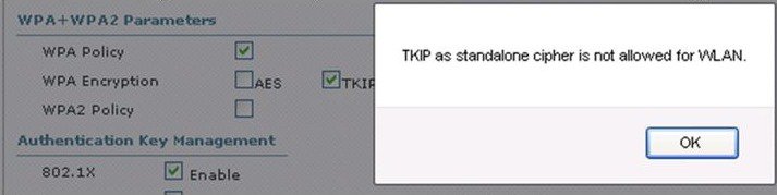
We developed a set of commands to configure TKIP from CLI mode only as was recommended by the Wi-Fi alliance:
If the same configuration is attempted from the GUI interface the following will be displayed on the screen:
AES Encryption
Figure 4-6 displays the basic AES counter mode/CBC MAC Protocol (CCMP) flow chart. CCMP is one of the AES encryption modes, where the counter mode provides confidentiality and CBC MAC provides message integrity.
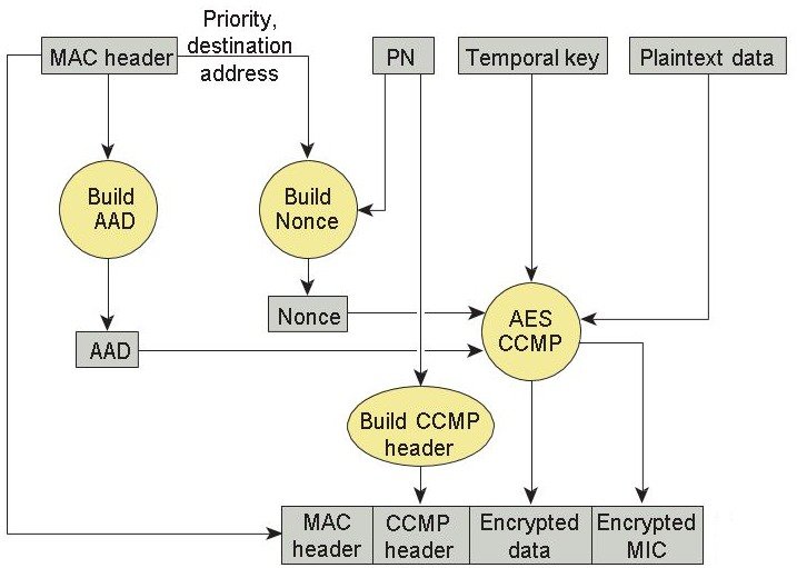
In the CCMP procedure, additional authentication data (AAD) is taken from the MAC header and included in the CCM encryption process. This protects the frame against alteration of the non-encrypted portions of the frame.
To protect against replay attacks, a sequenced packet number (PN) is included in the CCMP header. The PN and portions of the MAC header are used to generate a nonce that is in turn used by the CCM encryption process.
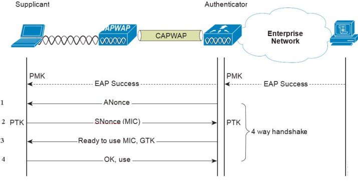
Four-Way Handshake
The four-way handshake is the method used to derive the encryption keys to encrypt wireless data frames. Figure 4-7 graphically represents the frame exchanges used to generate the encryption keys. These keys are referred to as temporal keys.
The encryption keys are derived from the PMK that is mutually derived during the EAP authentication. This PMK is sent to the authenticator in the EAP success message, but is not forwarded to the supplicant because the supplicant has derived its own copy of the PMK.
1.![]() The authenticator sends an EAPOL-Key frame containing an authenticator nonce (ANonce), which is a random number generated by the authenticator.
The authenticator sends an EAPOL-Key frame containing an authenticator nonce (ANonce), which is a random number generated by the authenticator.
The supplicant derives a PTK from the ANonce and supplicant nonce (SNonce), which is a random number generated by the client/supplicant.
2.![]() The supplicant sends an EAPOL-Key frame containing an SNonce, the RSN information element from the (re)association request frame, and an MIC.
The supplicant sends an EAPOL-Key frame containing an SNonce, the RSN information element from the (re)association request frame, and an MIC.
The authenticator derives a PTK from the ANonce and SNonce and validates the MIC in the EAPOL-Key frame.
3.![]() The authenticator sends an EAPOL-Key frame containing the ANonce, the RSN information element from its beacon or probe response messages; the MIC, determining whether to install the temporal keys; and the encapsulated group temporal key (GTK), the multicast encryption key.
The authenticator sends an EAPOL-Key frame containing the ANonce, the RSN information element from its beacon or probe response messages; the MIC, determining whether to install the temporal keys; and the encapsulated group temporal key (GTK), the multicast encryption key.
4.![]() The supplicant sends an EAPOL-Key frame to confirm that the temporal keys are installed.
The supplicant sends an EAPOL-Key frame to confirm that the temporal keys are installed.
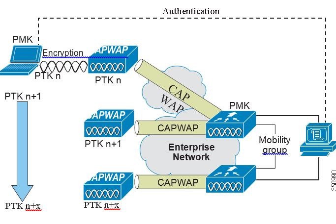
Proactive Key Caching (PKC) and CCKM
Proactive Key Caching (PKC) is an 802.11i extension that allows for the proactive caching (before the client roaming event) of the PMK that is derived during a client 802.1x/EAP authentication at the AP (see Figure 4-8). If a PMK (for a given WLAN client) is pre-cached at an AP, to which the client is about to roam, full 802.1x/EAP authentication is not required. Instead, the WLAN client can simply use the WPA four-way handshake process to securely derive a new session encryption key for communication with that AP.
The distribution of these cached PMKs to APs is greatly simplified in the Cisco Unified Wireless Network deployment. The PMK is simply cached in the controller(s) and made available to all APs that connect to it. The PMK is also shared with all other controllers that make up a mobility group with the anchor controller.
Figure 4-8 Proactive Key Caching Architecture
Cisco Centralized Key Management (CCKM) is a Cisco standard supported by Cisco Compatible Extensions clients to provide fast secure roaming (FSR). The principle mechanism for accelerating the roaming process is the same as PKC, which is to use a cached PMK. However, the implementation in CCKM is slightly different, which makes the two mechanisms incompatible with each other.
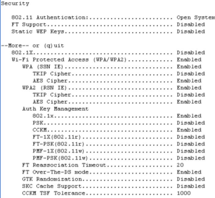
The state of the key cache for each WLAN client can be seen with the show pmk-cache all command. This identifies which clients are caching the keys, and which key caching mechanism is being used. The 802.11r workgroup is responsible for the standardization of an FSR mechanism for 802.11.
The WLC supports both CCKM and PKC on the same WLAN -802.1x+CCKM, as shown in the following example:
Cisco Unified Wireless Network Architecture
Figure 4-9 shows a high level topology of the Cisco Unified Wireless Network architecture that includes the CAPWAP APs, the mesh CAPWAPs, the management system (WCS/NCS/PI), and the wireless LAN controller (WLC).
The Cisco Access Control Server (ACS) or the Identity Services Engine (ISE) and their AAA features complete the solution by providing RADIUS services in support of wireless user authentication and authorization.
Figure 4-9 Cisco Unified Wireless Network Architecture
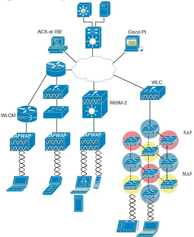
Figure 4-10 illustrates one of the primary features of the architecture: how APs use the CAPWAP protocol to communicate with and tunnel traffic to a WLC.
Figure 4-10 CAPWAP APs and WLC Connection

Cisco Unified Wireless Network Security Features
The native 802.11 security features combined with the physical security and ease of deployment of the CAPWAP architecture serves to improve the overall security of WLAN deployments. In addition to the inherent security benefits offered by the CAPWAP protocol, the Cisco Unified Wireless Network solution also includes the following additional security features:
- Enhanced WLAN security options
- ACL and firewall features
- Dynamic Host Configuration Protocol (DHCP) and Address Resolution Protocol (ARP) protection
- Peer-to-peer blocking
- Wireless intrusion protection system (wIPS)
Enhanced WLAN Security Options
The Cisco Unified Wireless Network solution supports multiple concurrent WLAN security options. For example, multiple WLANs can be created on a WLC, each with its own WLAN security settings that can range from an open guest WLAN network and WEP networks for legacy platforms to the combinations of WPA and/or WPA2 security configurations.
Each WLAN SSID can be mapped to either the same or different dot1q interface on the WLC, or Ethernet over IP (EoIP) tunneled to a different controller through a mobility anchor (Auto Anchor Mobility) connection.
If a WLAN client authenticates via 802.1x, a dot1q VLAN assignment can be controlled by way of RADIUS attributes passed to the WLC upon successful authentication.
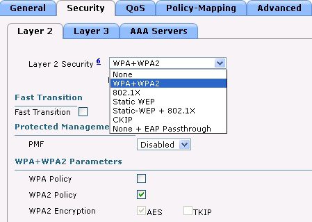
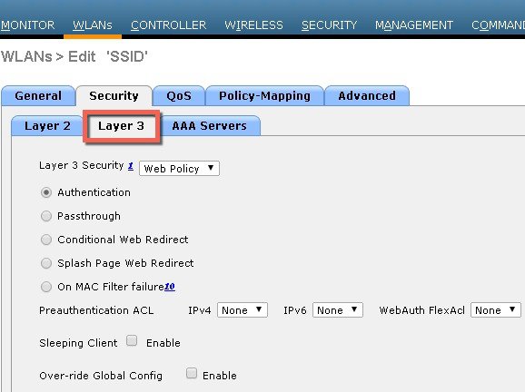
Figure 4-11, Figure 4-12 and Figure 4-13 show a subset of the Unified Wireless Network WLAN configuration screen. The following four main configuration items appears:
- The WLAN SSID
- The WLC interface to which the WLAN is mapped
- The Level 2security method (Figure 4-12)
- The Level 3 security method (Figure 4-13)
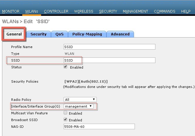
Figure 4-12 WLANs Layer 2 Security Tab
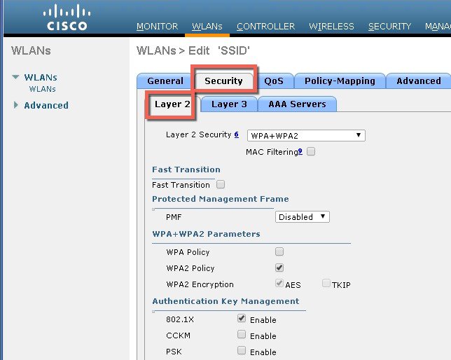
Figure 4-13 Wlan LAN security Layer 3
Local EAP Authentication
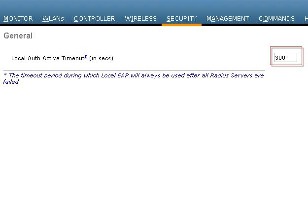
The WLC software provides local EAP authentication capability that can be used when an external RADIUS server is not available or becomes unavailable. The delay before switching to local authentication is configurable, as illustrated in Figure 4-14. When RADIUS server availability is restored, the WLC automatically switches back from local authentication to RADIUS server authentication.
Figure 4-14 Local Authentication Timeout
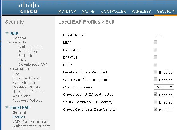
The EAP types supported locally on the WLC are LEAP, EAP-FAST, EAP-TLS, and PEAP.
Figure 4-15 displays the window where you can select the local EAP profiles.
Figure 4-15 Local EAP Profiles
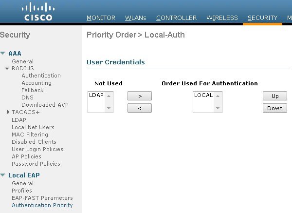
WLC can use its local database for authentication data, and it can also access an LDAP directory to provide data for EAP-FAST or EAP-TLS authentication. The user credential database priority (LDAP versus Local) is configurable, as shown in Figure 4-16.
Figure 4-16 Local EAP Priority
ACL and Firewall Features
An Access Control List (ACL) is a set of rules used to limit access to a particular interface (for example, if you want to restrict a wireless client from pinging the management interface of the controller). After ACLs are configured on the controller, they can be applied to the management interface, the AP-manager interface, any of the dynamic interfaces, or a WLAN to control data traffic to and from wireless clients or to the controller CPU to control all traffic destined for the CPU.
You may also want to create a pre-authentication ACL for web authentication. Such an ACL could be used to allow certain types of traffic before authentication is complete.
Both IPv4 and IPv6 ACL are supported. IPv6 ACLs support the same options as IPv4 ACLs including source, destination, source and destination ports.
You can enable only IPv4 traffic in your network by blocking IPv6 traffic. That is, you can configure an IPv6 ACL to deny all IPv6 traffic and apply it on specific or all WLANs.
- You can define up to 64 ACLs, each with up to 64 rules (or filters) for both IPv4 and IPv6. Each rule has parameters that affect its action. When a packet matches all of the parameters for a rule, the action set for that rule is applied to the packet.
- When you apply CPU ACLs on a Cisco 5500 Series Controller or a Cisco WiSM2, you must permit traffic towards the virtual interface IP address for web authentication.
- All ACLs have an implicit “deny all rule” as the last rule. If a packet does not match any of the rules, it is dropped by the controller.
- If you are using an external web server with a Cisco 5500 Series Controller or a controller network module, you must configure a pre-authentication ACL on the WLAN for the external web server.
- If you apply an ACL to an interface or a WLAN, wireless throughput is degraded when downloading from a 1-GBps file server. To improve throughput, remove the ACL from the interface or WLAN, move the ACL to a neighboring wired device with a policy rate-limiting restriction, or connect the file server using 100 Mbps rather than 1 Gbps.
- Multicast traffic received from wired networks that is destined to wireless clients is not processed by WLC ACLs. Multicast traffic initiated from wireless clients, destined to wired networks or other wireless clients on the same controller, is processed by WLC ACLs.
- ACLs are configured on the controller directly or configured through templates. The ACL name must be unique.
- You can configure ACL per client (AAA overridden ACL) or on either an interface or a WLAN. The AAA overridden ACL has the highest priority. However, each interface, WLAN, or per client ACL configuration that you apply can override one another.
- If peer-to-peer blocking is enabled, traffic is blocked between peers even if the ACL allows traffic between them.
- Authentication traffic has to go through the Cisco WLC for this feature to be supported, even if DNS-based ACL is local to the AP.
- When you create an ACL, it is recommended to perform the two actions (create an ACL or ACL rule and apply the ACL or ACL rule) continuously either from CLI or GUI.
Figure 4-17 displays the ACL Configuration page. The ACL can specify source and destination address ranges, protocols, source and destination ports, DSCP, and direction in which the ACL is to be applied. An ACL can be created out of a sequence of various rules.
Figure 4-17 ACL Configuration Page
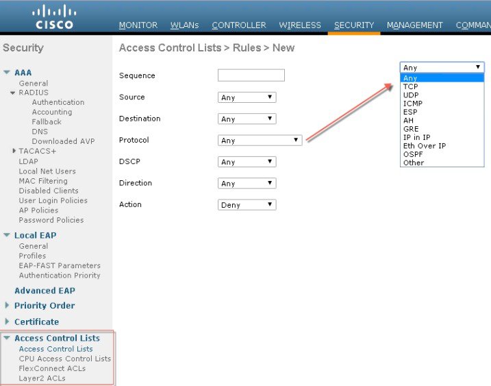
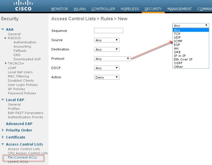
Figure 4-18 Illustration of Flex Connect ACL
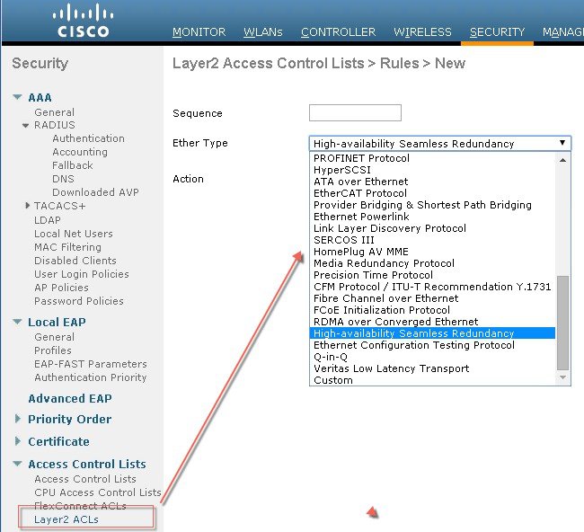
Layer 2 Access Control Lists
You can configure rules for Layer 2 access control lists (ACLs) based on the Ethertype associated with the packets. Using this feature, if a WLAN with central switching is required to support only PPPoE clients, you can apply Layer 2 ACL rules on the WLAN to allow only PPPoE packets after the client is authenticated and the rest of the packets are dropped. Similarly, if the WLAN is required to support only IPv4 clients or only IPv6 clients, you can apply Layer 2 ACL rules on the WLAN to allow only IPv4 or IPv6 packets after the client is authenticated and the rest of the packets are dropped. For a locally-switched WLAN, you can apply the same Layer 2 ACL either for the WLAN or a FlexConnect AP. AP-specific Layer 2 ACLs can be configured only on FlexConnect APs. This is applicable only for locally-switched WLANs. The Layer 2 ACL that is applied to the FlexConnect AP takes precedence over the Layer 2 ACL that is applied to the WLAN.
Figure 4-19 Illustration of Layer 2 ACL available for configuration on the WLC
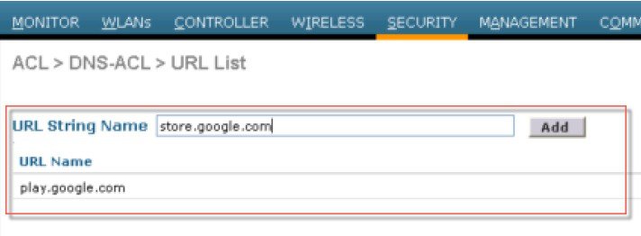
DNS-based Access Control Lists
The DNS-based ACLs are used for client devices such as Apple and Android devices. When using these devices, you can set pre-authentication ACLs on the Cisco WLC to determine where devices have the right to go.
To enable DNS-based ACLs on the Cisco WLC, you need to configure the allowed URLs for the ACLs. The URLs need to be pre-configured on the ACL.
With DNS-based ACLs, the client when in registration phase is allowed to connect to the configured URLs.
The Cisco WLC is configured with the ACL name and that is returned by the AAA server for pre-authentication ACL to be applied. If the ACL name is returned by the AAA server, then the ACL is applied to the client for web-redirection.
At the client authentication phase, the ISE server returns the pre-authentication ACL (url-redirect-acl). The DNS snooping is performed on the AP for each client until the registration is complete and the client is in SUPPLICANT PROVISIONING state. When the ACL configured with the URLs is received on the Cisco WLC, the CAPWAP payload is sent to the AP enabling DNS snooping on the client and the URLs to be snooped.
With URL snooping in place, the AP learns the IP address of the resolved domain name in the DNS response. If the domain name matches the configured URL, then the DNS response is parsed for the IP address, and the IP address is sent to the Cisco WLC as a CAPWAP payload. The Cisco WLC adds the IP address to the allowed list of IP addresses and thus the client can access the URLs configured.
Restrictions on DNS-based Access Control Lists
- Maximum of 10 URLs can be allowed for an access control list.
- For the Cisco WLC, 20 IP addresses are allowed for one client.
- Local authentication is not supported for FlexConnect APs.
- DNS-based ACLs are not supported on FlexConnect APs with Local Switching.
- DNS-based ACLs are not supported on Cisco 1130 and 1240 series access points.
- Authentication traffic has to go through the Cisco WLC to support this feature, even if DNS-based ACL is local to the AP.
- If a client is anchored, be it auto-anchor or after roaming, DNS-based ACLs do not work.
- DNS-based ACLs work only when RADIUS NAC (central web authentication or posture) are done on the SSID. DNS-based ACLs do not work with local web authentication or any other form of ACL other than a redirect-ACL used in the case of RADIUS NAC.
Figure 4-20 Illustration of DNS based ACL available for configuration on the WLC
DHCP and ARP Protection
The WLC acts as a relay agent for WLAN client DHCP requests. In doing so, the WLC performs a number of checks to protect the DHCP infrastructure. The primary check is to verify that the MAC address included in the DHCP request matches the MAC address of the WLAN client sending the request. This protects against DHCP exhaustion attacks, by restricting a WLAN client to one DHCP request (IP address) for its own interface. The WLC by default does not forward broadcast messages from WLAN clients back out onto the WLAN, which prevents a WLAN client from acting as a DHCP server and spoofing incorrect DHCP information.
The WLC acts as an ARP proxy for WLAN clients by maintaining the MAC address-IP address associations. This allows the WLC to block duplicate IP address and ARP spoofing attacks. The WLC does not allow direct ARP communication between WLAN clients. This also prevents ARP spoofing attacks directed at WLAN client devices.
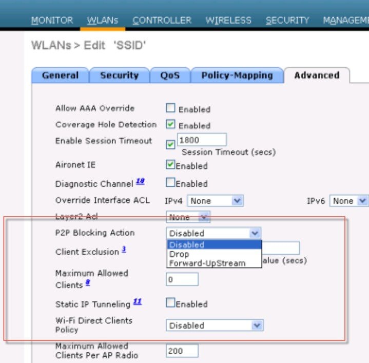
Peer-to-Peer Blocking
The WLC can be configured to block communication between clients on the same WLAN. This prevents potential attacks between clients on the same subnet by forcing communication through the router.
Figure 4-21 is the configuration screen for peer-to-peer blocking on the WLC.

Note![]() This is a not a global setting on the WLC and applies to a specific WLANs in later releases.
This is a not a global setting on the WLC and applies to a specific WLANs in later releases.
Figure 4-21 Peer-to-Peer Blocking
Wireless IDS
The WLC performs WLAN IDS analysis using information obtained from all of the connected APs, and reports detected attacks to WLC as well to the WCS. The Wireless IDS analysis is complementary to any analysis that can otherwise be performed by a wired network IDS system. The embedded Wireless IDS capability of the WLC analyzes 802.11and WLC-specific information that is not otherwise visible or available to a wired network IDS system.
The wireless IDS signature files used by the WLC are included in WLC software releases; however, they can be updated independently using a separate signature file. Custom signatures are displayed in the Custom Signatures window.
Figure 4-22 is the Standard Signatures window in the WLC.
Figure 4-22 Standard WLAN IDS Signatures

Cisco Adaptive Wireless Intrusion Prevention System
The Cisco Adaptive wireless Intrusion Prevention System (wIPS) is an advanced approach to wireless threat detection and performance management. It combines network traffic analysis, network device and topology information, signature-based techniques, and anomaly detection to deliver highly accurate and complete wireless threat prevention. With a fully infrastructure-integrated solution, you can continually monitor wireless traffic on both the wired and wireless networks and use that network intelligence to analyze attacks from many sources to more accurately pinpoint and proactively prevent attacks rather than waiting until damage or exposure has occurred.
The Cisco Adaptive wIPS is enabled by the Cisco Mobility Services Engine (MSE), which centralizes the processing of intelligence collected by the continuous monitoring of Cisco Aironet access points. With Cisco Adaptive wIPS functionalities and Cisco Prime Infrastructure integration into the MSE, the wIPS service can configure, monitor, and report wIPS policies and alarms.
The Cisco Adaptive wIPS is not configured on the controller. Instead, the Prime Infrastructure forwards the profile configuration to the wIPS service, which forwards the profile to the controller. The profile is stored in flash memory on the controller and sent to access points when they join the controller. When an access point disassociates and joins another controller, it receives the wIPS profile from the new controller. Local mode or FlexConnect mode access points with a subset of wIPS capabilities is referred to as Enhanced Local Mode access point or ELM AP. You can configure an access point to work in wIPS mode if the access point is in any of the following modes described below.
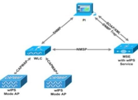
wIPS Communication Protocols
To provide communication between each system component, a number of protocols are utilized:
- CAPWAP (Control and Provisioning of Wireless Access Points)—This protocol is utilized for communication between Access Points and controllers. It provides a bi-directional tunnel in which alarm information is shuttled to the controller and configuration information is pushed to the Access Point. CAPWAP control messages are DTLS encrypted and CAPWAP data has the option to be DTLS encrypted.
- NMSP (Network Mobility Services Protocol)—This protocol is used for communication between Wireless LAN Controllers and the Mobility Services Engine. In the case of a wIPS Deployment, this protocol provides a pathway for alarm information to be aggregated from controllers to the MSE and for wIPS configuration information to be pushed to the controller. This protocol is encrypted.
- SOAP/XML (Simple Object Access Protocol)—This protocol is a method of communication between the MSE and PI. This protocol is used to distribute configuration parameters to the wIPS service running on the MSE.
- SNMP (Simple Network Management Protocol)—This protocol is used to forward wIPS alarm information from the Mobility Services Engine to the Prime Infrastructure. It is also utilized to communicate rogue access point information from the Wireless LAN Controller to the Prime Infrastructure.
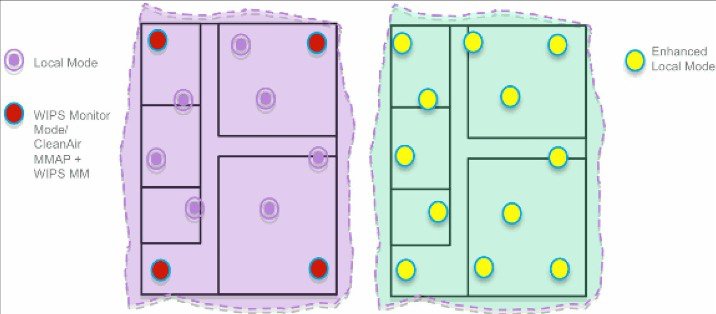
wIPS Deployment Modes
Beginning with the 7.4 Release, Cisco Adaptive Wireless IPS has three options for wIPS mode access points. To better understand the differences between the wIPS mode access points, lets discuss about each mode.
Local Mode with wIPS
Local Mode with wIPS provides wIPS detection “on-channel”, which means attackers will be detected on the channel that is serving clients. For all other channels, ELM provides best effort wIPS detection.
This means that every frame the radio would go “off-channel” for a short period of time. While "off-channel", if an attack occurs while that channel is scanned, the attack will be detected.
An example of Local Mode with wIPS on an AP3600, the 2.4 GHz radio is operating on channel 6. The AP will constantly monitor channel 6, any attacks on channel 6 will be detected and reported. If an attacker attacks channel 11, while the AP is scanning channel 11 “off-channel”, the attack will be detected.
- Adds wIPS security scanning for 7x24 on channel scanning (2.4 GHz and 5 GHz), with best effort off channel support.
- The access point is additionally serving clients and with the G2 Series of Access Points enables CleanAir spectrum analysis on channel (2.4 GHz and 5 GHz).
- Adaptive wIPS scanning in data serving local and FlexConnect APs.
- Protection without requiring a separate overlay network.
- Supports PCI compliance for the wireless LANs.
- Full 802.11 and non-802.11 attack detection.
- Adds forensics and reporting capabilities.
- Flexibility to set integrated or dedicated MM APs.
- Pre-processing at APs minimize data backhaul (that is, works over very low bandwidth links).
- Low impact on the serving data.
Monitor Mode
Monitor Mode provides wIPS detection "off-channel", which means the access point will dwell on each channel for an extend period of time, this allows the AP to detect attacks on all channels. The 2.4GHz radio will scan all 2.4GHz channels, while the 5GHz channel scans all 5GHz channels. An additional access point would need to be installed for client access.
Dedicated Monitor Mode versus ELM
Figure 4-23 illustrates a contrast between the standard deployments of wIPS monitor mode and APs with the ELM feature. The typical coverage range for both modes suggests:
- Dedicated wIPS monitor mode APs (shown in red in Figure 4-23) typically covers 15,000 to 35,000 square feet.
- APs with the ELM feature (shown in yellow in Figure 4-23) typically cover from 3,000 to 5,000 square feet.
Figure 4-23 Monitor Mode versus ELM
In the traditional wIPS deployment, a recommended ratio is 1 monitor mode AP to every 5 local mode APs (ratio can vary based on network design and expert guidance for best coverage). With ELM, you simply enable the ELM feature for all of the APs, effectively adding monitor mode wIPS operations to local data-serving mode AP while still maintaining performance.
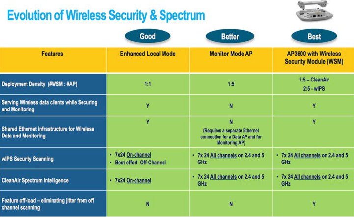
AP 3600/3700 with Wireless Security Module (WSM): The Evolution of Wireless Security and Spectrum
A Cisco 3600 series Access point with the WSM module uses a combination of "on-channel" and "off-channel". This means that the AP3600 2.4 GHz and 5 GHz will scan the channel that they are serving clients and the WSM module would operate in monitor mode and scan all channels.
Some of the features of the WSM Module are:
- Industry's first Access Point enabling the ability to simultaneously Serve clients, wIPS security scan, and analyze the spectrum using CleanAir Technology.
- Dedicated 2.4 GHz and 5 GHz radio with its own antennas enabling 7x24 scanning of all wireless channels in the 2.4 GHz and 5 GHz bands.
- A single Ethernet infrastructure provides simplified operation with fewer devices to manage and optimized return on investment of the AP3600 wireless infrastructure and the Ethernet wired infrastructure.
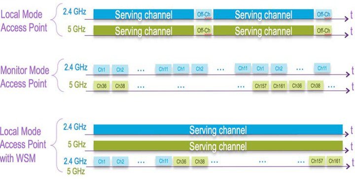
On-Channel and Off-Channel Performance
When an AP visits a channel, the time the AP stays on that channel, to detect and classify an attack, is known as the dwell time. ELM primary feature operates effectively for on-channel attacks, without any compromise to the performance on data, voice and video clients, and services. In contrast, the local mode varies off-channel scanning providing minimal dwell time to detect and classify an attack.
For example, due to radio resource management (RRM), when voice clients are associated to an AP scanning is deferred until the voice client is disassociated in order to ensure service is not affected. In this example, ELM detection during off-channel is considered best effort. Neighboring ELM APs operating on all/country/DCA channels increases effectiveness, hence the recommendation for enabling ELM on every local mode AP for maximum coverage protection. If your requirement is for dedicated scanning on all channels full-time, then we recommend deploying monitor mode APs.
Generally, the differences between local mode and monitor mode APs are:
- Local Mode AP—Serves WLAN clients with time slicing off-channel scanning, listens for 50 ms on each channel, and features configurable scanning for all/country/DCA channels.
- Monitor Mode AP—Does not serve WLAN clients, dedicated to scanning only, listens for 1.2 sec on each channel, and scans all channels.
The figure below explains the radio's behavior. When a radio is on its serving channel it is considered “on-channel”, when the radio is scanning other channels, it is considered "off-channel".
An AP in local mode is mostly "on-channel", making it difficult to detect attackers "off-channel". A monitor mode AP is always "off-channel", but cannot server clients, the WSM module provides a great combination of both.
ELM Across WAN Links
Cisco has optimized features in challenging topologies, such as deploying ELM APs across low bandwidth WAN links. The ELM feature involves pre-processing to determine attack signatures at the AP and is optimized to work over slower links. We recommend to test and measure the baseline to validate performance with ELM over WAN.
CleanAir Integration
Cisco CleanAir technology is a spectrum-aware, self-healing, and self-optimizing wireless network that mitigates the impact of wireless interference and offers performance protection for 802.11n networks.
The ELM feature compliments CleanAir operations with similar performance and benefits as monitor mode AP deployments, including these existing CleanAir spectrum-aware benefits:
ELM wIPS Alarm Flow
Attacks are only relevant when they occur on trusted APs. The ELM APs will detect an attack, then communicate, correlate, and report to the management system Cisco Prime Generally, the alarm flow process is:
1.![]() Attack is launched against a trusted AP.
Attack is launched against a trusted AP.
2.![]() Detection on the AP with ELM feature communicates through CAPWAP to WLC.
Detection on the AP with ELM feature communicates through CAPWAP to WLC.
3.![]() Passed transparently to MSE via NMSP.
Passed transparently to MSE via NMSP.
4.![]() Log into wIPS database on MSE and send to the management system Cisco Prime by way of an SNMP trap.
Log into wIPS database on MSE and send to the management system Cisco Prime by way of an SNMP trap.
Cisco Adaptive wIPS Alarms
The controller supports five Cisco Adaptive wIPS alarms that serve as notifications for potential threats. You must enable these alarms based on your network topology using Cisco Prime Infrastructure. For more details on this, see the Cisco Prime Infrastructure User Guide.
- Device not protected by VPN—The controller generates an alarm when a wireless client and access point does not communicate over secure VPN, as all controller traffic must be routed through a VPN connection.
- WPA Dictionary Attack—The controller generates an alarm when a dictionary attack on the WPA security key occurs. The attack is detected before the initial handshake message between the client and the access point.
- WiFi Direct Session Detected—The controller generates an alarm when Wifi direct sessions of clients are detected with Wifi direct and prevents enterprise vulnerability.
- RSN Info Element Out-of-Bound Denial-of-Service—The controller generates an alarm when there are large values for RSN information element that results in an access point crash.
- DS Parameter Set DoS—The controller generates an alarm when confusion exists in the channel for the client while multiple channels overlap.
The Adaptive wIPS system follows a linear chain of communication to propagate attack information obtained from scanning the airwaves to the console of the Prime Infrastructure.
Figure 4-24 Threat Detection Alarm Flow
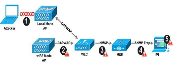
1.![]() In order for an alarm to be triggered on the Cisco Adaptive wIPS system, an attack must be launched against a legitimate Access Point or Client. Legitimate Access Points and clients are discovered automatically in a Cisco Unified Wireless Network by 'trusting' devices broadcasting the same 'RF-Group' name. In this configuration, the system dynamically maintains a list of local-mode Access Points and their associated clients. The system can also be configured to 'trust' devices by SSID using the SSID Groups feature. Only attacks, which are considered harmful to the WLAN infrastructure, are propagated upwards to the rest of the system.
In order for an alarm to be triggered on the Cisco Adaptive wIPS system, an attack must be launched against a legitimate Access Point or Client. Legitimate Access Points and clients are discovered automatically in a Cisco Unified Wireless Network by 'trusting' devices broadcasting the same 'RF-Group' name. In this configuration, the system dynamically maintains a list of local-mode Access Points and their associated clients. The system can also be configured to 'trust' devices by SSID using the SSID Groups feature. Only attacks, which are considered harmful to the WLAN infrastructure, are propagated upwards to the rest of the system.
2.![]() Once an attack has been identified by the wIPS Mode Access Point engine, an alarm update is sent to the Wireless LAN Controller and is encapsulated inside the CAPWAP control tunnel.
Once an attack has been identified by the wIPS Mode Access Point engine, an alarm update is sent to the Wireless LAN Controller and is encapsulated inside the CAPWAP control tunnel.
3.![]() The Wireless LAN Controller will transparently forward the alarm update from the Access Point to the wIPS Service running on the Mobility Services Engine. The protocol used for this communication is NMSP.
The Wireless LAN Controller will transparently forward the alarm update from the Access Point to the wIPS Service running on the Mobility Services Engine. The protocol used for this communication is NMSP.
4.![]() Once received by the wIPS Service on the Mobility Services Engine, the alarm update will be added to the alarm database for archival and attack tracking. An SNMP trap is forwarded to the Prime Infrastructure containing the attack information. If multiple alarm updates are received referencing the same attack (for example, if multiple Access Points hear the same attack) only one SNMP trap will be sent to Prime Infrastructure.
Once received by the wIPS Service on the Mobility Services Engine, the alarm update will be added to the alarm database for archival and attack tracking. An SNMP trap is forwarded to the Prime Infrastructure containing the attack information. If multiple alarm updates are received referencing the same attack (for example, if multiple Access Points hear the same attack) only one SNMP trap will be sent to Prime Infrastructure.
5.![]() The SNMP trap containing the alarm information is received and displayed by Prime Infrastructure.
The SNMP trap containing the alarm information is received and displayed by Prime Infrastructure.
Deployment Considerations - Required Components
The basic system components for a Cisco Adaptive wIPS system include:
- Access Points in wIPS Monitor Mode, in Local Mode with wIPS, or with a wireless security module
- Wireless LAN Controller(s)
- A Mobility Services Engine running the wIPS Service
- A Prime Infrastructure
The minimum code versions required for an Adaptive wIPS system:
- Available with Cisco Mobility Services Engine Software Release 5.2.xxx or later
- Requires Cisco Prime Infrastructure, version 1.3.
- Requires 7.2.xxx or later on Cisco Wireless LAN Controllers
- Release 7.2 and later wireless IPS functionality requires monitor mode (that is, non-client-serving) access points
- Release 7.2.xxx and later wireless IPS functionality requires access points in local mode with wIPS (that is, client-serving)
The minimum code versions required for the Wireless Security Module (WSM):
How Many wIPS Access Points do I need?
Before deploying an Adaptive wIPS system, it is important to consider that the communications range of an access point's cell is less than the actual range at which frames may be received and decoded. The reason for this discrepancy is that an Access Point's communication range is limited by the weakest link - which in typical deployments is the WLAN client. Given that the output power of a WLAN client is intrinsically less than the Access Point's maximum, the range of the cell is restricted to the client's abilities. In addition, it is recommended practice to run Access Points at less than full power to build RF redundancy and load balancing into the wireless network. These aforementioned fact combined with the superior receive sensitivity of Cisco's Access Points allows the Adaptive wIPS system to be deployed with less access point density than the client serving infrastructure while still providing pervasive monitoring.
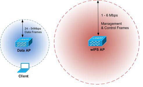
As depicted in the above diagram, a wIPS deployment is based on hearing 802.11 management and control frames which are used by a majority of attacks to cause harm. This is in contrast to a data Access Points deployment that is surveyed to provide higher throughput data rates anywhere from 24Mbps to 54Mbps.
There are numerous factors that go into deciding exactly the number of wIPS Access Points that are required for a specific environment. Given that each prospective deployment's security requirements and environmental conditions are different, there is no hard and fast rule that will address the needs of every deployment but a few generalized guidelines must be taken into account.
The main factors, which affect the number of wIPS Access Points required, are as follows.
Access Point Density Recommendations
The square footage of access point coverage can be measured based on frequency and environment, but with the newer wIPS modes, other factors also contribute to wIPS access point density recommendations. All access point modes can monitor the same distance, but due to the reasons below, we recommend to deploy each mode with a different density.
Access Points in local mode with wIPS are geared towards serving clients. For local mode with wIPS deployments, it is recommended for every access point be put in local mode with wIPS.
For monitor mode access points, we recommend that a ratio of 1:5 local mode to monitor mode access points.
Finally for the WSM module, there is a single radio monitoring all channels on both the 2.4 GHz and 5 GHz band. Since radio has additional channels to scan, it is recommended that the WSM module be deployed with a 2:5 density to speed up detection time.
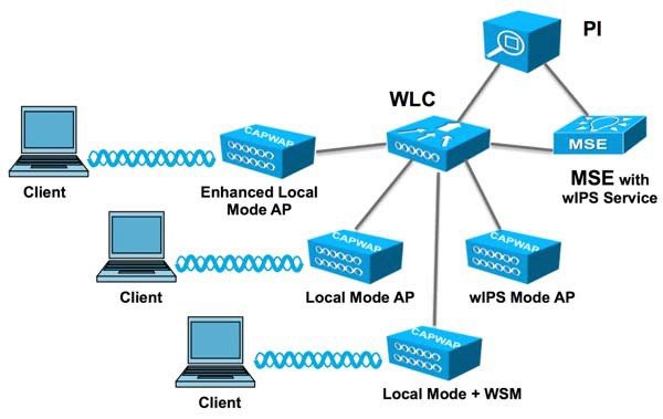
wIPS Integrated in a Cisco Unified Wireless Network
An integrated wIPS deployment is a system design in which non-wIPS Mode Access Points and wIPS Mode Access Points are intermixed on the same controller(s) and managed by the same Prime Infrastructure. This can be any combination of local mode, flex connect mode, local mode with wIPS, monitor mode, and 3600 series Access points with the WSM module. Overlaying wIPS protection and data shares many of the components including controllers and Prime Infrastructure thus reducing duplicate infrastructure costs.
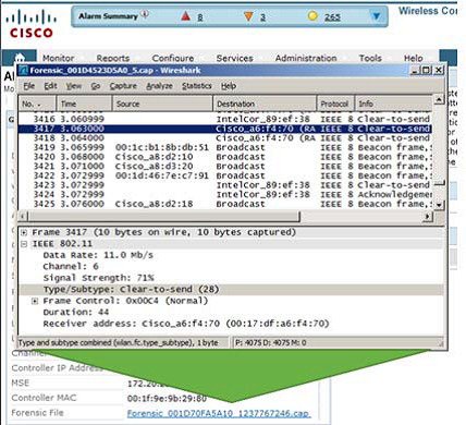
Forensics
The Cisco Adaptive wIPS system provides the ability to capture attack forensics for further investigation and troubleshooting purposes. At a base level, the forensics capability is a toggle-based packet capture facility, which provides the ability to log and retrieve a set of wireless frames. This feature is enabled on a per attack basis from within the wIPS profile configuration of PI.
Once enabled, the forensics feature is triggered once a specific attack alarm is seen over the airwaves. The forensic file will be created based on the packets contained within the buffer of the wIPS Mode AP that triggered the original alarm. This file is transferred to the Wireless LAN Controller via CAPWAP, which then forwards the forensic file via NMSP to the wIPS Service running on the Mobility Services Engine. The file is stored within the forensic archive on the MSE until the user configured disk space limit for forensics is reached. By default this limit is 20 GB, which when reached will cause the oldest forensic files to be removed. Access to the forensic file can be obtained by opening the alarm on the Prime Infrastructure, which contains a hyperlink to the forensic file. The files are stored as a '.CAP' file format which can be opened by either WildPacket's Omnipeek, AirMagnet Wi-Fi Analyzer, Wireshark or any other packet capture program which supports this format. See Wireshark for detailed information.
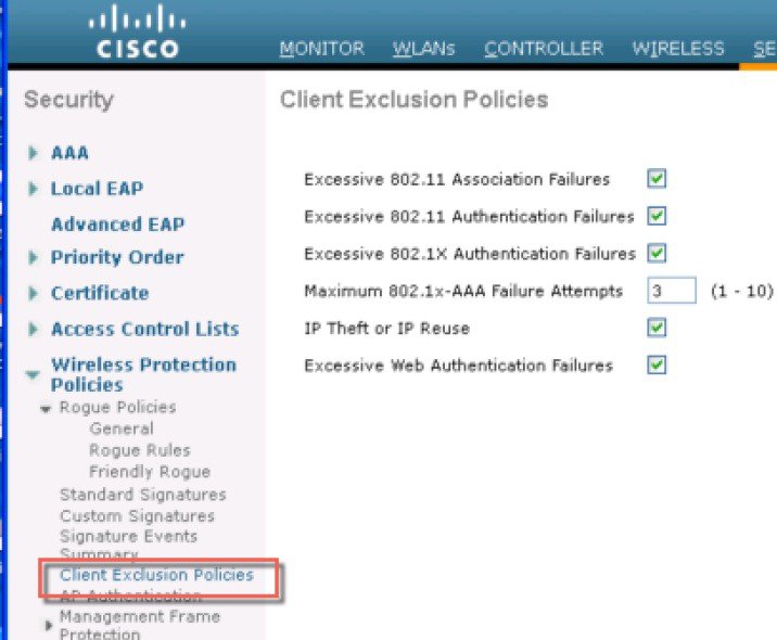
Client Exclusion
In addition to Wireless IDS, the WLC is able to take additional steps to protect the WLAN infrastructure and WLAN clients. The WLC is able to implement policies that exclude WLAN clients whose behavior is considered threatening or inappropriate. Figure 4-25 shows the Exclusion Policies window, containing the following currently supported client exclusion policies:
- Excessive 802.11 association failures—Possible faulty client or DoS attack
- Excessive 802.11 authentication failures—Possible faulty client or DoS attack
- Excessive 802.1X authentication failures—Possible faulty client or DoS attack
- Maximum 802.1X —AAA Failure Attempts (1-10)
- IP theft or IP reuse—Possible faulty client or DoS attack
- Excessive web authentication failures—Possible DoS or password-cracking attack
Figure 4-25 Client Exclusion Policies
Managing Rogue Devices and Policies
Rogue access points can disrupt wireless LAN operations by hijacking legitimate clients and using plain-text or other denial-of-service or man-in-the-middle attacks. That is, a hacker can use a rogue access point to capture sensitive information, such as usernames and passwords. The hacker can then transmit a series of Clear to Send (CTS) frames. This action mimics an access point, informing a particular client to transmit, and instructing all the other clients to wait, which results in legitimate clients being unable to access network resources. Wireless LAN service providers have a strong interest in banning rogue access points from the air space.
Rogue Location Discovery Protocol
Cisco Rogue Location Discovery Protocol (RLDP) is an active approach, which is used when rogue AP has no authentication (Open Authentication) configured. This mode, which is disabled by default, instructs an active AP to move to the rogue channel and connect to the rogue as a client. During this time, the active AP sends de-authentication messages to all connected clients and then shuts down the radio interface. Then, it associates to the rogue AP as a client. The AP then tries to obtain an IP address from the rogue AP and forwards a User Datagram Protocol (UDP) packet (port 6352) that contains the local AP and rogue connection information to the controller through the rogue AP. If the controller receives this packet, the alarm is set to notify the network administrator that a rogue AP was discovered on the wired network with the RLDP feature. RLDP has 100% accuracy in rouge AP detection. It detects Open APs and NAT APs.
Detecting Rogue Devices
The controller continuously monitors all the nearby access points and automatically discovers and collects information on rogue access points and clients. When the controller discovers a rogue access point, it uses the Rogue Location Discovery Protocol (RLDP) and the rogue detector mode access point is connected to determine if the rogue is attached to your network.
Controller initiates RLDP on rogue devices that have open authenticated and configured. If RLDP uses Flexconnect or local mode access points, then clients are disconnected for that moment. After the RLDP cycle, the clients are reconnected to the access points. As and when rogue access points are seen (auto-configuration), the RLDP process is initiated.
You can configure the controller to use RLDP on all the access points or only on the access points configured for the monitor (listen-only) mode. The latter option facilitates automated rogue access point detection in a crowded radio frequency (RF) space, allowing monitoring without creating unnecessary interference and without affecting the regular data access point functionality. If you configure the controller to use RLDP on all the access points, the controller always chooses the monitor access point for RLDP operation if a monitor access point and a local (data) access point are both nearby. If RLDP determines that the rogue is on your network, you can choose to contain the detected rogue either manually or automatically.
RLDP detects on wire presence of the rogue access points that are configured with open authentication only once, which is the default retry configuration.
Figure 4-26 Illustration of the RLDP configuration
A rogue access point is moved to a contained state either automatically or manually. The controller selects the best available access point for containment and pushes the information to the access point. The access point stores the list of containments per radio. For auto containment, you can configure the controller to use only the monitor mode access point.
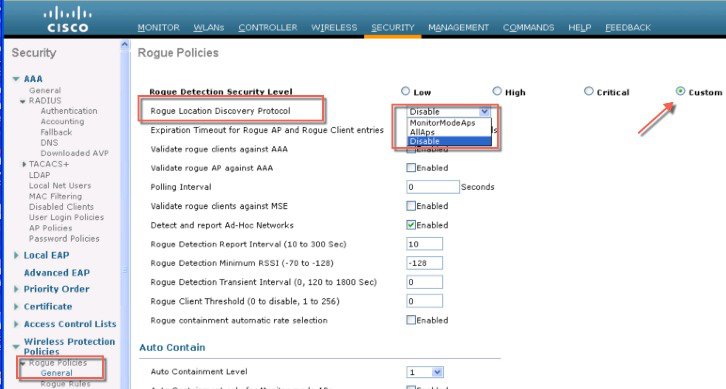
Rogue Detection Policies Parameters
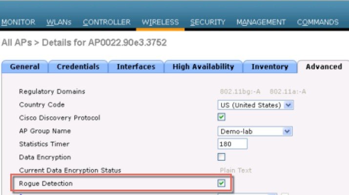
Make sure that rogue detection is enabled for the corresponding access points. Rogue detection is enabled by default for all access points joined to the controller (except for OfficeExtend access points).
1.![]() Rogue Detection Security Level following options:
Rogue Detection Security Level following options:
- Low —Basic rogue detection for small-scale deployments.
- High —Basic rogue detection with auto containment for medium-scale deployments.
- Critical —Basic rogue detection with auto containment and RLDP for highly sensitive deployments.
- Custom —For auto RLDP, the security level should be set to Custom mode. There should not be any scheduling for RLDP even in the Custom mode.
2.![]() Rogue Location Discovery Protocol AP options:
Rogue Location Discovery Protocol AP options:
- Disable —Disables RLDP on all the access points. This is the default value.
- All APs —Enables RLDP on all the access points.
- Monitor Mode APs —Enables RLDP only on the access points in the monitor mode.
3.![]() Rogue Client Validation —use the AAA, MSE server or local database to validate if rogue clients are valid clients, select the Validate Rogue Clients.
Rogue Client Validation —use the AAA, MSE server or local database to validate if rogue clients are valid clients, select the Validate Rogue Clients.
MSE responds with information about whether the rogue client is a valid learned client or not. The controller can contain or consider the rogue client as a threat.
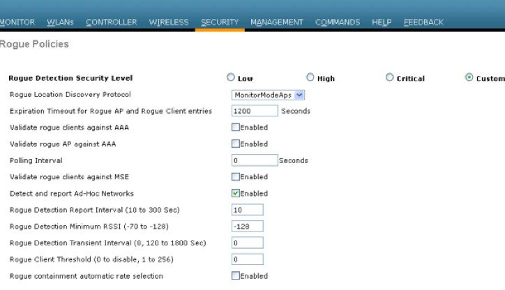
4.![]() Detect and Report Ad-Hoc Networks —if necessary select ad hoc rogue detection and reporting.
Detect and Report Ad-Hoc Networks —if necessary select ad hoc rogue detection and reporting.
5.![]() Rogue Detection Report Interval —the time interval, in seconds, at which APs should send the rogue detection report to the controller. The valid range is 10 seconds to 300 seconds, and the default value is 10 seconds.
Rogue Detection Report Interval —the time interval, in seconds, at which APs should send the rogue detection report to the controller. The valid range is 10 seconds to 300 seconds, and the default value is 10 seconds.
6.![]() Rogue Detection Minimum RSSI —the minimum Received Signal Strength Indicator (RSSI) value that a rogue entry should have for APs to detect the rogue and for a rogue entry to be created in the controller. The valid range is -128 dBm to -0 dBm, and the default value is 0 dBm. This feature is applicable to all the AP modes. There can be many rogues with very weak RSSI values that do not provide any valuable information in rogue analysis. Therefore, you can use this option to filter rogues by specifying the minimum RSSI value at which APs should detect rogues.
Rogue Detection Minimum RSSI —the minimum Received Signal Strength Indicator (RSSI) value that a rogue entry should have for APs to detect the rogue and for a rogue entry to be created in the controller. The valid range is -128 dBm to -0 dBm, and the default value is 0 dBm. This feature is applicable to all the AP modes. There can be many rogues with very weak RSSI values that do not provide any valuable information in rogue analysis. Therefore, you can use this option to filter rogues by specifying the minimum RSSI value at which APs should detect rogues.
7.![]() Rogue Detection Transient Interval —time interval at which a rogue should be scanned for by the AP after the first time the rogue is scanned. After the rogue is scanned for consistently, updates are sent periodically to the controller. Thus, the APs filter the transient rogues, which are active for a very short period and are then silent. The valid range is between 120 seconds to 1800 seconds, and the default value is 0. The rogue detection transient interval is applicable to the monitor mode APs only.
Rogue Detection Transient Interval —time interval at which a rogue should be scanned for by the AP after the first time the rogue is scanned. After the rogue is scanned for consistently, updates are sent periodically to the controller. Thus, the APs filter the transient rogues, which are active for a very short period and are then silent. The valid range is between 120 seconds to 1800 seconds, and the default value is 0. The rogue detection transient interval is applicable to the monitor mode APs only.
This feature has the following advantages:
- Rogue reports from APs to the controller are shorter.
- Transient rogue entries are avoided in the controller.
- Unnecessary memory allocation for transient rogues are avoided.
8.![]() Rogue Client Threshold —the threshold value. A value of 0 disables the rogue client threshold parameter.
Rogue Client Threshold —the threshold value. A value of 0 disables the rogue client threshold parameter.
9.![]() Rogue Containment Automatic Rate Selection —Using this option, you can optimize the rate to use the best rate for the target rogue. The AP selects the best rate based on rogue RSSI.
Rogue Containment Automatic Rate Selection —Using this option, you can optimize the rate to use the best rate for the target rogue. The AP selects the best rate based on rogue RSSI.
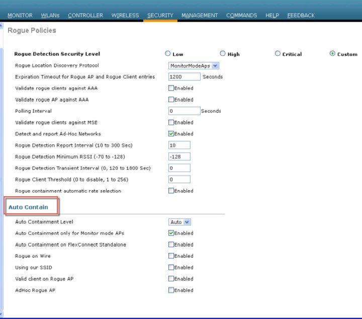
10.![]() Containment —If you want the controller to automatically contain certain rogue devices, enable the following parameters.
Containment —If you want the controller to automatically contain certain rogue devices, enable the following parameters.
- Auto Containment Level —Set the auto containment level. By default, the auto containment level is set to 1. If you choose Auto, the controller dynamically chooses the number of APs required for effective containment.
- Auto Containment only for Monitor mode APs —Configure the monitor mode access points for auto-containment.
- Auto Containment on FlexConnect Standalone —Standalone StaFlexConnect Standalone mode access points for auto containment.
- The auto-containment is continued if it was configured when the AP was in connected FlexConnect mode. After the standalone AP reassociates with the controller, auto containment is stopped and the future course of action is determined by the configuration on the controller that the AP is associated with. You can also configure auto containment on the ad hoc SSIDs and managed SSIDs on FlexConnect APs.
- Rogue on Wire —Configure the auto containment of rogues that are detected on the wired network.
- Using Our SSID —Configure the auto containment of rogues that are advertising your network's SSID. If you leave this parameter unselected, the controller only generates an alarm when such a rogue is detected.
- Valid Client on Rogue AP —Valid Client on Rogue APed, the controller only generates an alarm when such a rogue associated. If you leave this parameter unselected, the controller only generates an alarm when such a rogue is detected.
- AdHoc Rogue AP —Rogue APue AP this parameter unselected, the controller only generates an alarm when such this parameter unselected, the controller only generates an alarm when such a network is detected.

" Using this feature may have legal consequences. Do you want to continue?"
The 2.4-GHz and 5-GHz frequencies in the Industrial, Scientific, and Medical (ISM) band are open to the public and can be used without a license. As such, containing devices on another party's network could have legal consequences.
Figure 4-27 Illustrates Rogue Policies configuration options; RLDP security levels and enablement on the Aps; also it shows the validation configuration against AAA or MSE.
Figure 4-27 Configuring Rogue Policies
Rogue AP
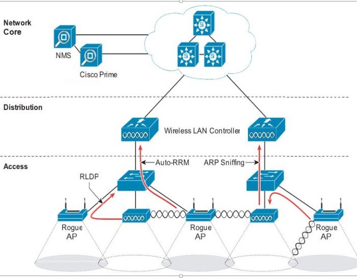
The Cisco Unified Wireless Networking solution, as shown in Figure 4-28, provides a complete solution for rogue APs. This solution provides:
- Air/RF detection—Detection of rogue devices by observing/sniffing beacons and 802.11 probe responses.
- Rogue AP location—Use of the detected RF characteristics and known properties of the managed RF network to locate the rogue device.
- Wire detection—A mechanism for tracking/correlating the rogue device to the wired network.
- Rogue AP isolation—A mechanism to prevent client connection to a rogue AP.
Figure 4-28 Unified Wireless Network Rogue AP Detection
Air/RF Detection
The two AP RF detection deployment models are:
Both deployment models support RF detection and are not limited to rogue APs, but can also capture information upon detection of ad-hoc clients and rogue clients (the users of rogue APs). An AP that is configured for monitor mode is dedicated to scanning the RF channels and does not support client association or data transmission.
When searching for rogue APs, an AP goes off channel for 50 ms to listen for rogue clients, and to monitor noise and channel interference. The channels scanned are configured in the global WLAN network parameters for 802.11a and 802.11b/g.
Any detected prospective rogue client(s) and/or access points are sent to the controller to gather the following information:
- Rogue AP MAC address
- Rogue AP name
- Rogue connected client(s) MAC address
- Whether the frames are protected with WPA, WEP and WEP2
- The preamble
- Signal-to-noise ratio (SNR)
- Received signal strength indication (RSSI)
- Switchport tracing
The prospective rogue client/AP is not labeled a rogue until the WLC receives another report from a trusted AP or until the completion of a second detection cycle. The trusted AP moves to the same channel, as the prospective rogue, to monitor for rogue client/AP, noise, or interference. If the same client/AP is detected a second time, they are then labeled as rogue on the WLC.
Once labeled as a rogue, the WLC determines if this rogue is attached to the local network or is simply a neighboring AP. In either case, an AP that is not part of the managed Cisco Unified Wireless Network is considered a rogue.
In monitor mode, the trusted AP does not carry user traffic; it is dedicated to scanning channels. This mode of deployment is most common when a customer does not want to support WLAN services in a particular area, but wants to monitor that area for rogue APs and rogue clients.
Location
The location features of Cisco Prime Infrastructure can be used to provide a floor plan indicating the approximate location of a rogue AP. The floor plan displays the location of all legitimate APs, and highlights the location of a rogue AP with the skull-and-crossbones icon. For additional information on the Cisco Unified Wireless Network location features, see Cisco Wireless Location Appliance.
Wire Detection
Situations can exist where the Cisco Prime Infrastructure rogue location feature is not effective, such as in branch offices with only a few APs or where floor plan information might not be available. In these cases, the Cisco Unified Wireless Network solution offers two wire-based detection options:
If an AP is configured as a rogue detector, its radio is turned off and its role is to listen on the wired network for MAC addresses of clients associated to rogue APs; that is, rogue clients. The rogue detector listens for ARP packets that include rogue client MAC addresses. When it detects one of these ARPs, it reports this to the WLC, providing verification that the rogue AP is attached to the same network as the Cisco Unified Wireless Network.
To maximize the likelihood of capturing ARP information, the rogue AP detector is connected to all available broadcast domains using a Switched Port Analyzer (SPAN) port. Multiple rogue AP detector APs can be deployed to capture the various aggregated broadcast domains that exist on a typical network.
If a rogue client resides behind a wireless router (a common home WLAN device), its ARP requests are not seen on the wired network, so an alternative to the rogue detector AP method is needed. Additionally, rogue detector APs might not be practical for some deployments because of the large number of broadcast domains to be monitored (such as in the main campus network).
The RLDP option can aid in these situations. In this case, a standard AP, upon detecting a rogue AP, can attempt to associate with the rogue AP as a client and send a test packet to the controller, which requires the AP to stop behaving as a standard AP and temporarily go into client mode. This action confirms that the rogue AP in question is actually on the network, and provides IP address information that indicates its logical location in the network. Given the difficulties in deriving location information in branch offices coupled with the likelihood of a rogue being located in multi-tenant buildings, rogue AP detector and RLDP are useful tools that augment location-based rogue AP detection.
Switch Port Tracing
The Cisco Prime Infrastructure provides rogue access point detection by retrieving information from the controller. The rogue access point table is populated with any detected BSSID addresses from any frames that are not present in the neighbor list. A neighbor list contains the known BSSID addresses of validated APs or neighbors. At the end of a specified interval, the contents of the rogue table are sent to the controller in a CAPWAP Rogue AP Report message. With this method, the Cisco Prime Infrastructure simply gathers the information received from controllers. Additionally, you can also incorporate auto or manual switch port tracing (SPT) of wired rogue access point switch ports. The auto SPT is preferable for a large wireless network.
Auto SPT launches automatically when a rogue AP is reported to the Cisco Prime Infrastructure. The auto SPT provides a quicker scan based on the wired location association of the rogue AP. The Cisco Prime Infrastructure allows you to configure the criteria for auto SPT and auto containment so that you can run a trace and contain the detected rogue access points on the wire.
When the multiple controllers report that a rogue AP should be auto contained, the Cisco Prime Infrastructure finds the controller that reports the strongest RSSI and sends the containment request to the controller.
Rogue AP Containment
Rogue AP connected clients, or rogue ad-hoc connected clients, can be contained by sending 802.11 de-authentication packets from nearby APs. This should be done only after steps have been taken to ensure that the AP is truly a rogue AP, because it is illegal to do this to a legitimate AP in a neighboring WLAN. This is why the automatic rogue AP containment feature is removed from the solution.
To determine whether rogue AP clients are also clients on the enterprise WLAN, the client MAC address can be compared with MAC addresses collected by the AAA during 802.1X authentication. This allows for the identification of potential WLAN clients that might have been compromised or users who are not following security policies.
Management Frame Protection
One of the challenges in 802.11 has been that management frames are sent in the clear with no encryption or message integrity checking and are therefore vulnerable to spoofing attacks. WLAN management frame spoofing can be used to attack a WLAN network. To address this, we created a digital signature mechanism to insert a message integrity check (MIC) into 802.11 management frames. This allows legitimate members of a WLAN deployment to be identified, as well as being able to identify rogue infrastructure devices, and spoofed frames through their lack of valid MICs.
The MIC used in management frame protection (MFP) is not a simple CRC hashing of the message, but also includes a digital signature component. The MIC component of MFP ensures that a frame has not been tampered with, and the digital signature component ensures that the MIC could have only been produced by a valid member of the WLAN domain. The digital signature key used in MFP is shared among all controllers in a mobility group; different mobility groups have different keys allowing validation of all WLAN management frames processed, by the WLCs, in that mobility group (Figure 4-29).
Figure 4-29 Management Frame Protection
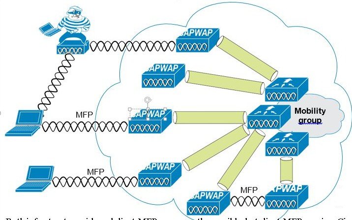
Both infrastructure-side and client MFP are currently possible, but client MFP requires Cisco Compatible Extensions v5 WLAN clients to learn the mobility group MFP key before they can detect and reject invalid frames.
MFP provides the following benefits:
- Authenticates 802.11 management frames generated by the WLAN network infrastructure.
- Allows detection of malicious rogues that spoof a valid AP MAC or SSID to avoid detection as a rogue AP, or as part of a man-in-the-middle attack.
- Increases the effectiveness of the rogue AP and WLAN IDS signature detection of the solution.
- Provides protection of client devices using Cisco Compatible Extensions v5.
- Supported by standalone AP.
Two steps are required to enable MFP: enabling it under the Security tab on the WLC (Figure 4-30) and enabling it on the WLANs in the mobility group (Figure 4-26).
Figure 4-30 Enabling MFP on the Controller
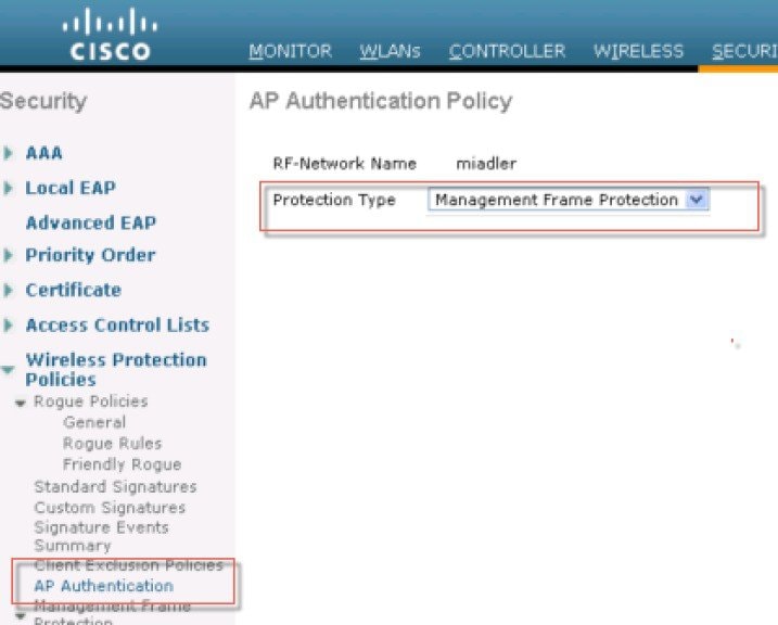
Management System Security Features
Apart from providing location support for Rogue AP detection, the management system Cisco Prime provides two additional Unified Wireless Network security features: WLC configuration verification management and an alarm and reporting interface.
Configuration Verification
The management system Cisco Prime can provide on-demand or regularly-scheduled configuration audit reports, which compare the complete current running configuration of a WLC and its registered access points with that of a known valid configuration stored in the management system Cisco Prime databases. Any exceptions between the current running configuration and the stored database configuration are noted and brought to the attention of the network administrator via screen reports ().
Alarms and Reports
Apart from the alarms that can be generated directly from a WLC and sent to an enterprise network management system Cisco Prime, where the management system can also send alarm notifications. The primary difference between alarm notification methods, apart from the type of alarm sent by the various components, is that the WLC uses Simple Network Management Protocol (SNMP) traps to send alarms (which can be interpreted only by an NMS system), whereas the management system Cisco Prime uses SMTP e-mail to send an alarm message to an administrator.
The management system Cisco Prime provides both real-time and scheduled reports, and can export or e-mail reports. The management system Cisco Prime provides reports on:
Cisco TrustSec SXP
The Cisco TrustSec enables organizations to secure their networks and services through identity-based access control to anyone, anywhere, anytime. The solution also offers data integrity and confidentiality services, policy-based governance, and centralized monitoring, troubleshooting, and reporting services. TrustSec can be combined with personalized, professional service offerings to simplify solution deployment and management, and is a foundational security component to Cisco Borderless Networks.
The Cisco TrustSec security architecture builds secure networks by establishing domains of trusted network devices. Each device in the domain is authenticated by its peers. Communication on the links between devices in the domain is secured with a combination of encryption, message integrity check, and data-path replay protection mechanisms. Cisco TrustSec uses the device and user credentials acquired during authentication for classifying the packets by security groups (SGs) as they enter the network. This packet classification is maintained by tagging packets on ingress to the Cisco TrustSec network so that they can be correctly identified to apply security and other policy criteria along the data path. The tag, called the security group tag (SGT), allows the network to enforce the access control policy by enabling the endpoint device to act upon the SGT to filter traffic. Cisco TrustSec security group tag is applied only when you enable AAA override on a WLAN.
One of the components of Cisco TrustSec architecture is the security group-based access control. In the security group-based access control component, access policies in the Cisco TrustSec domain are topology-independent, based on the roles (as indicated by security group number) of source and destination devices rather than on network addresses. Individual packets are tagged with the security group number of the source.
Cisco devices use the SGT Exchange Protocol (SXP) to propagate SGTs across network devices that do not have hardware support for Cisco TrustSec. SXP is the software solution to avoid CTS hardware upgrade on all switches. WLC will be supporting SXP as part of TrustSec Architecture. The SXP sends SGT information to the CTS-enabled switches so that appropriate role-based access control lists (RBACLs) can be activated depending on the role information represented by the SGT. By default, the controller always works in the Speaker mode. To implement the SXP on a network, only the egress distribution switch needs to be CTS-enabled, and all the other switches can be non-CTS-capable switches.
The SXP runs between any access layer and distribution switch or between two distribution switches. The SXP uses TCP as the transport layer. CTS authentication is performed for any host (client) joining the network on the access layer switch similar to an access switch with CTS-enabled hardware. The access layer switch is not CTS hardware enabled. Therefore, data traffic is not encrypted or cryptographically authenticated when it passes through the access layer switch. The SXP is used to pass the IP address of the authenticated device, that is a wireless client, and the corresponding SGT up to the distribution switch. If the distribution switch is CTS hardware enabled, the switch inserts the SGT into the packet on behalf of the access layer switch. If the distribution switch is not CTS hardware enabled, the SXP on the distribution switch passes the IP-SGT mapping to all the distribution switches that have CTS hardware. On the egress side, the enforcement of the RBACL occurs at the egress L3 interface on the distribution switch.
The following are some guidelines for Cisco TrustSec SXP:
–![]() MAC Filtering using RADIUS servers
MAC Filtering using RADIUS servers
–![]() Web authentication using RADIUS servers for user authentication
Web authentication using RADIUS servers for user authentication
For more information, see Cisco TrustSec.
Restrictions for Cisco TrustSec SXP
- SXP is not supported on FlexConnect access points.
- SXP is supported only in centrally switched networks that have central authentication.
- By default, SXP is supported for APs that work in local mode only.
- The configuration of the default password should be consistent for both controller and the switch.
- Fault tolerance is not supported because fault tolerance requires local switching on APs.
- Static IP-SGT mapping for local authentication of users is not supported.
- IP-SGT mapping requires authentication with external ACS servers.
- In auto-anchor/guest-anchor mobility the SGT information passed by the RADIUS server to foreign WLC can be communicated to the anchor WLC through the EoIP/CAPWAP mobility tunnel. The anchor WLC can then build the SGT-IP mapping and communicate it to another peer via SXP.
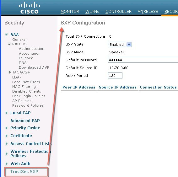
Password Policies
The password policies allows administrator to enforce strong password checks on newly created passwords for additional management users of controller and access point. The following are the requirements enforced on the new password:
- When the controller is upgraded from old version, all the old passwords are maintained as it is, even though the passwords are weak. After the system upgrade, if strong password checks are enabled, the same is enforced from that time and the strength of previously added passwords will not be checked or altered.
- Depending on the settings done in the Password Policy page, the local management, access point, management use and SNM3 user configuration is affected.
Figure 4-31 illustrates the password policies for Local Management User, AP, Management User and SNMPv3 user.
Figure 4-31 Password Policies - Local Management User and AP
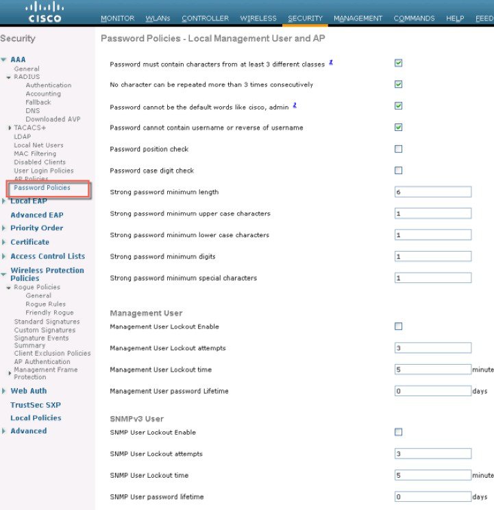
 Feedback