Overview of Cisco Beacon Point

This guide introduces you to the Cisco Beacon Point and provides instructions on how to install and mount the this device.

About Cisco Beacon Point

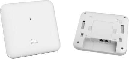
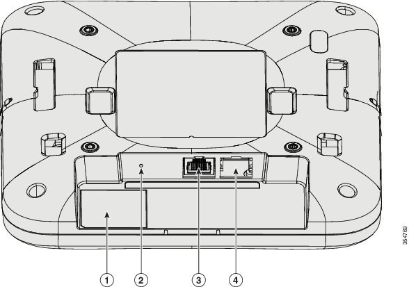
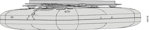
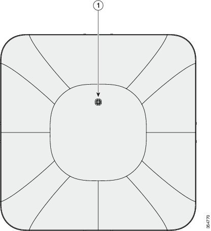
Cisco Beacon Point (AIR-VBLE1-K9) is a Bluetooth Low Energy (BLE version v4.2) beacon point, and includes a BLE transmitter with 16 antenna in a sector geometry and 1 omni-directional antenna element. You must connect Cisco Beacon Point Ethernet Port Eth0 to a PoE switch to power on the device. This creates eight virtual beams that are essential to create virtual beacons. The smart device receives signals from multiple Cisco Beacon Points with different strengths.

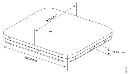
Cisco Beacon Point deployment is similar to any Wi-Fi location based service solution. The recommended density for deploying Cisco Beacon Point is 1 per 2500 sq.ft. The recommended height for the Cisco Beacon Point is 13 ft (3.9 m). Cisco Beacon Center requires the correct physical orientation, position, and height of Cisco Beacon Point for providing clients with indoor navigation, turn-by-turn guidance and proximity messaging for best indoor navigation experience.

Cisco Beacon Points connect with Cisco Beacon Center over the internet using secure HTTPS protocol. Each Cisco Beacon Point has a unique IP address just like any enterprise grade networking device. Cisco Beacon Point should connect with Cisco Beacon Center for management and control. Allow the port numbers 80 (TCP) and 443 (TCP, UDP) to be open from the firewall or configure an access control list (ACL) policy permitting the same within the enterprise network.

Figure 1. Cisco Beacon Point (AIR-VBLE1-K9)

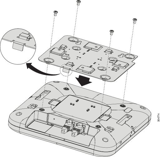
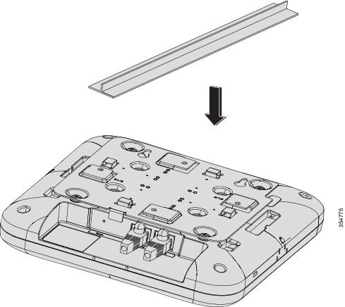
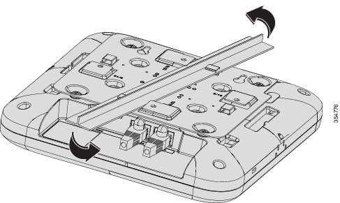
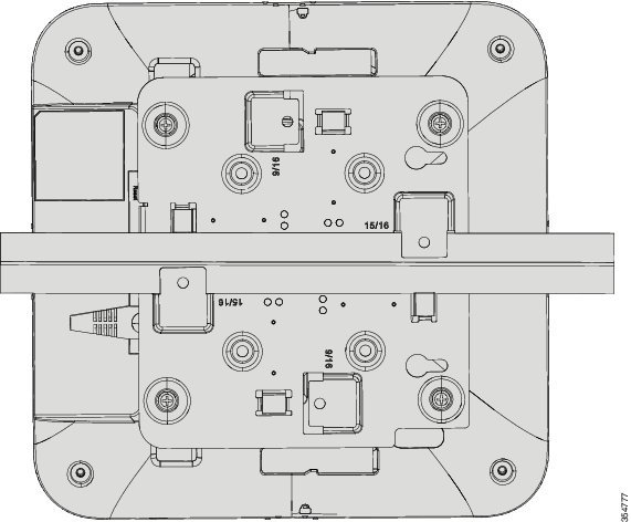
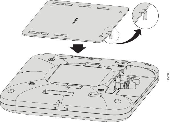
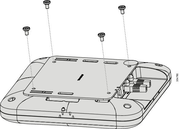
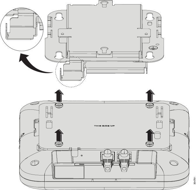
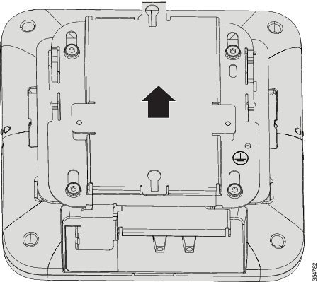
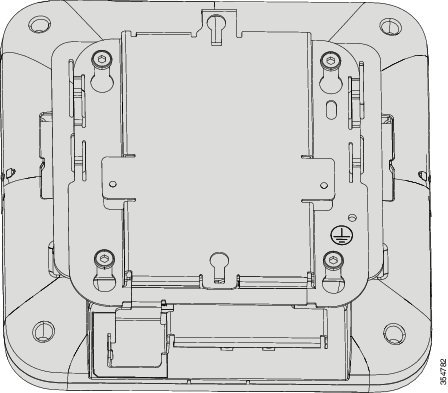
You have multiple mounting options:

  • T-Bar Mounting Bracket(AIR-AP-BRACKET-4)—Mount Cisco Beacon Point to a T-bar. This is the default option.

  • Cisco Adaptor Mounting Bracket(AIR-AP-VBLE-ADPTR)—Mount Cisco Beacon Point to an existing Cisco AIR-AP-BRACKET-1 or AIR-AP-BRACKET-2. Order this bracket separately if needed.

Cisco Beacon Point Features

Cisco Beacon Point comes with the following features:

Table 1. Hardware Feature Summary

Feature

Description

Radio Frequency

2.4-GHz Bluetooth Low Energy (BLE) 4.2 internal antenna array.

Eth0 + Power over Ethernet (PoE) in port

A PoE in port, which is a 10/100/1000 BaseT RJ45 interface. This supports 802.3at and 802.3af power supplies.

Eth1 + Power over Ethernet (PoE) out port A PoE out port, which is a 48-54V, 10/100/1000 BaseT RJ45 interface. This port is not enabled and is for future use only.

LED indicators

A multicolor system status LED on the front-face of the unit.

There are no LEDs for the Ethernet RJ45 ports.

Reset button

A recessed button that resets a Cisco Beacon Point to factory settings when pressed after the Cisco Beacon Point is powered up.

Power Options

  • PoE sourced from a switch that is connected on the Eth0 port.

  • External PoE injector (AIR-PWRINJ5) on the Eth0 port.

Physical Security

Option to add a Kensington lock.

Technical Specifications

Table 2. Technical Specifications of Cisco Beacon Point

Feature

Description

Dimensions

203 mm x 203 mm x 40 mm

7.99 in x 7.99 in x 1.57 in

Weight

0.636 kg (1.4 lbs)

Compliance standards

UL 60950-1

CAN/CSA-C22.2 No. 60950-1

FCC Part 15.247, 15.407, 15.107, and 15.109

FCC Part 15 Class B

RSS-247

ICES-003 (Canada)

Environmental

Fanless operation; passive cooling

Nonoperating (storage) temperature: -30 to 70℃ (-22 to 158℉)

Operating temperature: 0 to 40℃ (32 to 104℉)

Operating humidity: 10 to 90% (noncondensing)

Operating altitude: 9843 ft (3000 m)

Power Dissipation

Less than 6W

Cisco Beacon Point Model Number

Cisco Beacon Point is available in the following model:

Table 3. Cisco Beacon Point Model Number

Product ID

Description

AIR-VBLE1-K9

Cisco Beacon Point with internal antennas.

Installing a Cisco Beacon Point

Unpacking a Cisco Beacon Point

Procedure


Step 1

Unpack and remove a Cisco Beacon Point and the mounting accessories from the shipping box.

Step 2

Return the packing material to the shipping container and save it for future use.

Step 3

Verify that you have received the item listed below. If an item is missing or is damaged, contact your Cisco representative or reseller for instructions.

  • T-Bar Mounting Bracket—AIR-AP-BRACKET-4 with four Phillips wafer-head screws.

  • Sandwich Bracket—Acoustic Tile Bracket with two Phillips wafer-head screws.

Step 4

Record the MAC address and CLAIM CODE of the Cisco Beacon Point and then use it to claim the Cisco Beacon Point from Cisco Beacon Center.


Ports and Connectors on the Cisco Beacon Point

Figure 2. Back of Cisco Beacon Point

1

Location of MAC address and Claim code.

2

A recessed reset button that resets the device to factory settings when powered up.

3

Eth1 + Power over Ethernet (PoE) out port. For future use only.

4

Eth0 + Power over Ethernet (PoE) in port, a PoE in port, which is a 10/100/1000 BaseT RJ45 interface.

Figure 3. Side of Cisco Beacon Point

1

Kensington lock slot

Mounting the Cisco Beacon Point

The following sections provide information about the different ways in which Cisco Beacon Point can be mounted:

Mounting a Cisco Beacon Point to a T-bar

Mount a Cisco Beacon Point to a T-bar using a mounting bracket, AIR-AP-BRACKET-4. This bracket is shipped with a Cisco Beacon Point. You can order a spare, if required.

Procedure

Step 1

Install the AIR-AP-BRACKET-4 bracket to a Cisco Beacon Point using the four wafer-head screws provided.

Step 2

Line up the T-bar with Cisco Beacon Point such that the tab on the bracket is aligned with the wall of Cisco Beacon Point with the input-output ports.

Step 3

Install Cisco Beacon Point to the T-bar. Twist and lock it into place. You should hear a click.

Step 4

Note the orientation and position of Cisco Beacon Point on the floor plan loaded into Cisco Beacon Center.


Mounting Cisco Beacon Point to an Existing AIR-AP-BRACKET-1 or AIR-AP-BRACKET-2

Mount a Cisco Beacon Point to an existing Cisco AIR-AP-BRACKET-1 or AIR-AP-BRACKET-2 using the mounting bracket AIR-AP-VBLE-ADPTR. The AIR-AP-VBLE-ADPTR kit includes four Torx shoulder screws, which must be ordered separately from Cisco.


Note

Use this method only if you do not want to replace your existing brackets with the bracket provided with your Cisco Beacon Point.


Procedure

Step 1

Install AIR-AP-VBLE-ADPTR bracket using the four Torx shoulder screws provided with the Cisco Beacon Point. Ensure that the THIS SIDE UP marking on the AIR-AP-VBLE-ADPTR is facing upwards.

Step 2

Mount Cisco Beacon Point to the existing Cisco AIR-AP-BRACKET-1 or AIR-AP-BRACKET-2. Ensure that the tab is facing down and aligned with the wall of Cisco Beacon Point containing input-output ports ports.

Step 3

Slide until Cisco Beacon Point locks to the bracket.

Step 4

Make a note the orientation and position of the Cisco Beacon Point on the floor plan loaded into the Cisco Beacon Center.


Mounting to an Acoustic Tile

Before you begin

Acoustic Tile Mounting mounting is performed using a mounting bracket Acoustic Tile Bracket, which can be used to mount a Cisco Beacon Point array. This bracket is shipped with theCisco Beacon Point. You can order a spare, if required.

Procedure

Step 1

Install the Acoustic Tile Bracket bracket to the acoustic tile using the two screws provided. Use screws which have a head diameter of 7mm and a length of 40mm. Tighten the screws to secure the bracket to the tile.

Step 2

Position the Cisco Beacon Point below the installed Acoustic Tile Bracket bracket.

Step 3

Slide to lock the Cisco Beacon Point to the bracket. You should hear a click.


Checking the Cisco Beacon Point LEDs

Figure 4. Face of Cisco Beacon Point

1

Location of the Status LED


Note

Small variations in color intensity and hue will be present from unit to unit. This is within the normal range of the LED manufacturer’s specifications, and is not a defect.

Cisco Beacon Point status LED indicates various conditions, which are described in the table below:

Table 4. Cisco Beacon Point LED Status Indication

LED Color

Cisco Beacon Point LED Status

Blinking red

Cisco Beacon Point beginning a boot reset.

Alternating green and yellow

Cisco Beacon Point booting.

White

Cisco Beacon Point connecting to Cisco Beacon Center.

Green

Cisco Beacon Point configured by Cisco Beacon Center.

Blinking orange

Cisco Beacon Point upgrading.

Alternating green and purple

Locating a Cisco Beacon Point in Cisco Beacon Center.

Blinking amber

Cisco Beacon Point failure mode.

OFF turning to red

Reset to factory default button pressed by the user.

White turning to OFF

Cisco Beacon Point about to reset.

Powering on a Cisco Beacon Point

Cisco Beacon Point can be powered on in the following ways:

  • Power over Ethernet (PoE) using a switch on the Eth0 port.

  • External PoE injector (AIR-PWRINJ5) on the Eth0 port.

When Cisco Beacon Point is powered ON accurately, the Cisco Beacon Point LED turns from blink red to solid green. In case of errors, refer to the Checking the Cisco Beacon Point LEDs for information about the LED blinking states.

Safety Warnings, Caution Notices, and Notes


Warning

IMPORTANT SAFETY INSTRUCTIONS

This warning symbol means danger. You are in a situation that could cause bodily injury. Before you work on any equipment, be aware of the hazards involved with electrical circuitry and be familiar with standard practices for preventing accidents. Use the statement number provided with each warning to locate its translation in the translated safety warnings that accompanied this device.

Statement 1071

Warning

Read the installation instructions before you connect the system to its power source. (Statement 1004)

Warning

Installation of the equipment must comply with local and national electrical codes.(Statement 1074)

Warning

This product relies on the building’s installation for short-circuit (over-current) protection. Ensure that the protective device is rated not greater than 20A (Statement 1005)

Warning

Do not operate your wireless network device near unshielded blasting caps or in an explosive environment unless the device has been modified for such use. (Statement 245B)

Caution

The fasteners you use to mount a Cisco Beacon Point on a ceiling must be capable of maintaining a minimum pullout force of 20 lbs (9 kg) and must use a minimum of four holes on the mounting bracket, or a minimum of two holes when mounting on a network box.

Caution

This product and all the interconnected equipment must be installed indoors within the same building, including the associated LAN connections, as defined by Environment A of the IEEE 802.3af/at Standard.

Note

Cisco Beacon Point is suitable for use in environmental air space in accordance with Section 300.22.C of the National Electrical Code and Sections 2-128, 12-010(3), and 12-100 of the Canadian Electrical Code, Part 1, C22.1. You should not install the power injector in air-handling spaces

Note

Use only with listed Information Technology Equipment (ITE). For more information on ITE, refer to Article 645 of the latest National Electrical Code (NEC).