Overview of Cisco Beacon Point Module
About Cisco Beacon Point Module
Cisco Beacon Point Module (AIR-RM-VBLE2-K9=) is a Bluetooth Low Energy beacon module that is mounted on supported access points. The APs now has the ability to provide Wi-Fi access as well as act as BLE Beacons for Bluetooth-integrated clients. With Cisco Beacon Point Module, smart client devices can receive different signal strengths from the multiple integrated beacon to improve location calculations.
Deploying Bluetooth-integrated APs is similar to Wi-Fi location based service solution. The recommended density for deploying the Bluetooth-integrated APs is one per 1500-to-2500 sq.ft. The optimum height for a Bluetooth-integrated APs is 13 to 15 ft (3.9 to 4.6m). Cisco Beacon Center requires the correct physical orientation, position, and height of Bluetooth-integrated APs for providing clients with indoor navigation, turn-by-turn guidance and proximity messaging for best indoor navigation experience.
Bluetooth-integrated APs connect with Cisco Beacon Center over the internet using secure HTTPS protocol. Bluetooth-integrated APs, each have a unique IP address just like any enterprise grade networking device. Bluetooth-integrated APs should connect with Cisco Beacon Center for management and control. For Bluetooth-integrated APs to communicate with the Cisco Beacon Center, outbound communications from Cisco Beacon Point Module to the cloud service using port 80 (TCP) and 443 (TCP) must be possible.
|
Number |
Description |
|---|---|
|
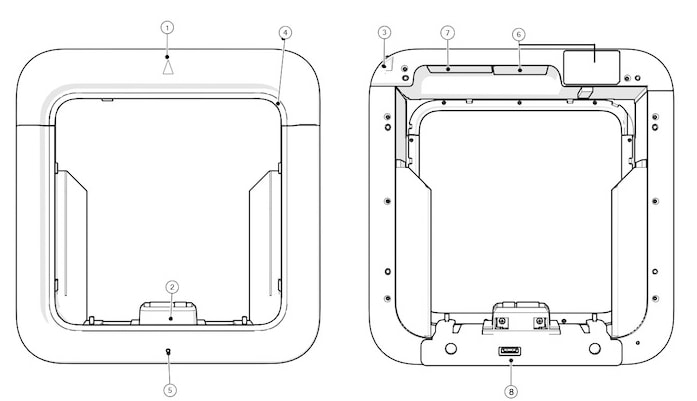
1 |
Cisco Beacon Point Module pointing direction. |
|
2 |
Host interface connector to access point. Draws power from the host bus interface with the access point. |
|
3 |
Cisco Beacon Point Module swing arm latch screw. |
|
4 |
Decorative gasket:
|
|
5 |
LED status indicator. A multicolor system status LED on the front-face of the unit. Note that you can vary (dim) the strength of this LED from the cloud settings. |
|
6 |
Serial Number, MAC, Claim code labels |
|
7 |
Regulatory labels |
|
8 |
Console port (covered with mylar label at manufacturing). |
Supported Access Points
The Cisco Beacon Point Module can be attached to the following APs:
-
AP3802I
-
AP3802E
Cisco Beacon Point Module Features
Cisco Beacon Point Module comes with the following features:
|
Feature |
Description |
|---|---|
|
LED indicators |
A multicolor system status LED on the front-face of the unit. Note that you can vary (dim) the strength of this LED from the cloud settings. |
|
Power Options |
Draws power from the PCIe bus interface with the access point. |
Technical Specifications
|
Feature |
Description |
|---|---|
|
Dimensions (of APs with Cisco Beacon Point Module) |
285 mm x 275 mm x 61 mm 11.2 in. x 10.8 in. x 2.4 in. |
|
Weight |
1.4 kg (3.0 lbs) |
|
Environmental |
Fanless operation; passive cooling Nonoperating (storage) temperature: – 30 to 70℃ (– 22 to 158℉) Operating temperature: 0 to 40℃ (32 to 104℉) Operating humidity: 10 to 90% (noncondensing) Operating altitude: 10,000 ft (3048 m) |
|
Power Dissipation |
Less than 6 W |
Cisco Beacon Point Module Model Number
Cisco Beacon Point Module is available in the following model:
|
Product ID |
Description |
|---|---|
| AIR-RM-VBLE2-K9= |
Cisco Beacon Point Module can be mounted on supported APs. Note that while the Cisco Beacon Point Module must be attached to supported APs, the Cisco Beacon Point itself is a standalone device. |


 Feedback