System Operation and Configuration

The ASR 5500 is designed to provide subscriber management services for Mobile Packet Core networks.

Before you connect to the command line interface (CLI) and begin system configuration, you must understand how the system supports these services. This chapter provides terminology and background information to consider before you configure the system.

System Management Overview

ASR 5000 management capabilities reflect the requirements of the Telecommunications Management Network (TMN) model for network element (NE) and element management system (EMS) functions. The system also supports external element management applications via standards-based protocols (CORBA and SNMPv1, v2). Wireless operators can readily integrate the ASR 5000 into their overall network, service, and business management systems. All management is performed out-of-band for security and to maintain system performance.

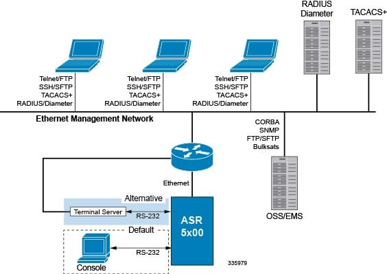
There are multiple ways to manage the system either locally or remotely using its out-of-band management interfaces.

Figure 1. System Management Interfaces
Management options include:
  • Local login through the Console port on the SPIO card via an RS-232 Console connection (RJ45) directly or indirectly via a terminal server

  • Remote login using Telnet, and Secure Shell (SSH) access to the CLI through the SPIO card's Ethernet management interfaces:

    • Two auto-sensing RJ45 10/100/1000Base-TX shielded twisted pair (STP) ports OR

    • Two optical MMF 1000Base-SX SFP 802.3z-compliant Gigabit Ethernet ports


    Important


    In release 20.0 and higher Trusted StarOS builds, the Telnet and FTP options are not available.


  • Support for Common Object Request Broker Architecture (CORBA) via an Object Request Broker Element Manager (ORBEM) interface and Simple Network Management Protocol version 1 (SNMPv1) and version 2 (SNMPv2) for fault management

  • Authentication via RADIUS/Diameter or TACACS+

The StarOS CLI provides complete Fault, Configuration, Accounting, Performance, and Security (FCAPS) capabilities as described in the remaining chapters of this guide.


Important


By default StarOS supports local Console access to the CLI via the RS-232 Console port for initial system configuration.


Terminology

This section defines important terms used throughout this guide.

Contexts

A context is a logical grouping or mapping of configuration parameters that pertain to various physical ports, logical IP interfaces, and services. A context can be thought of as a virtual private network (VPN).

The system supports the configuration of multiple contexts. Each context is configured and operates independently of the others. Once a context has been created, administrative users can configure services, logical IP interfaces, and subscribers for that context and then bind the logical interfaces to physical ports.

You can also assign a domain alias to a context; if a subscriber's domain name matches one of the configured alias names for a context, that context is used.

Ports

Ports are the physical connectors on line cards that support remote access and subscriber traffic. Port configuration includes traffic profiles, data encapsulation methods, media type, and other information for physical connectivity between the system and the rest of the network.

Ports are identified by the chassis slot number for the line card, followed by the physical connector number. For example, Port 24/1 identifies connector number 1 on the SPIO card in slot 24.

Associate ports with contexts through bindings. For additional information on bindings, refer to the Bindings section below. You can configure each physical port to support multiple logical IP interfaces, each with up to 17 IP addresses (one primary and up to 16 secondaries).

For complete information on line cards and port assignments, refer to the ASR 5000 Installation Guide.

Logical Interfaces

You must associate a port with a StarOS virtual circuit or tunnel called a logical interface before the port can allow the flow of user data.Within StarOS, a logical interface is a named interface associated with a virtual router instance that provides higher-layer protocol transport, such as Layer 3 IP addressing. Interfaces are configured as part of VPN contexts and are independent from the physical ports that will be used to bridge the virtual interfaces to the network.

Logical interfaces are associated with ethernet+ppp+tunnel addresses and are bound to a specific port during the configuration process. Logical interfaces are also associated with services through bindings. Services are bound to an IP address that is configured for a particular logical interface. When associated, the interface takes on the characteristics of the functions enabled by the service.

There are several types of logical interfaces to configure to support Simple and Mobile IP data applications. These are briefly defined below.

Management Interface

This interface provides the point of attachment to the management network. The interface supports remote access to the command line interface (CLI). It also supports event notification via the Simple Network Management Protocol (SNMP).

Define management interfaces in the local context and bind them to the ports on the Switch Processor Input/Output (SPIO) cards.

Bindings

A binding is an association between elements within the system. There are two types of bindings: static and dynamic.

Static binding is accomplished through system configuration. Static bindings associate:
  • A specific logical interface (configured within a particular context) to a physical port. Once the interface is bound, traffic can flow through the context as if it were any physically-defined circuit. Static bindings support any encapsulation method over any interface and port type.

  • A service to an IP address assigned to a logical interface within the same context. This allows the interface to take on the characteristics (that is, support the protocols) required by the service.

Dynamic binding associates a subscriber to a specific egress context based on the configuration of their profile or system parameters. This provides a higher degree of deployment flexibility, as it allows a wireless carrier to support multiple services and facilitates seamless connections to multiple networks.

Management ports can only be bound in the local context. Traffic or subsciber ports can only be bound in a non-local context.

Services

Configure services within a context to enable certain functionality. The following are examples of services you can configure on the system, subject to licensing availability and platform type:

  • Gateway GPRS Support Node (GGSN) services

  • Serving GPRS Support Node (SGSN) Services

  • Packet Data Serving Node (PDSN) services

  • Foreign Agent (FA) services

  • Home Agent (HA) services

  • Layer 2 Tunneling Protocol Access Concentrator (LAC) services

  • Dynamic Host Control Protocol (DHCP) services

  • Mobility Management Entity (MME) Services

  • PDN Gateway (P-GW) Services

  • Serving Gateway (S-GW) Services

  • Home-NodeB Gateway (HNB-GW) Services

  • Evolved Packet Data Gateway (ePDG)

  • Intelligent Policy Control Function (IPCF) Services (PCC-Service, PCC-Policy, PCC-AF)

AAA Servers

Authentication, Authorization and Accounting (AAA) servers store profiles, perform authentication, and maintain accounting records for each mobile data subscriber. The AAA servers communicate with the system over an AAA interface. The system supports the configuration of up to 128 interfaces to AAA servers.

It is important to note that for Mobile IP, there can be Foreign AAA (FAAA) and Home AAA (HAAA) servers. FAAA servers typically reside in the carrier's network. HAAA servers could be owned and controlled by either the carrier or the home network. If the HAAA server is owned and controlled by the home network, accounting data is transferred to the carrier via an AAA proxy server.


Important


As AAA applications do not support the indirectly connected hosts, configure only the directly connected host.


Important


Mobile IP support depends on the availability and purchase of a standalone license or a license bundle that includes Home Agent (HA).


Subscribers

Subscribers are the end-users of the service; they gain access to the Internet, their home network, or a public network through the system.

There are three primary types of subscribers:
  • RADIUS-based Subscribers: The most common type of subscriber, these users are identified by their International Mobile Subscriber Identity (IMSI) number, an Electronic Serial Number (ESN), or by their domain name or user name. They are configured on and authenticated by a RADIUS AAA server.

    Upon successful authentication, various attributes that are contained in the subscriber profile are returned. The attributes dictate such things as session parameter settings (for example, protocol settings and IP address assignment method), and what privileges the subscriber has.


    Important


    Attribute settings received by the system from a RADIUS AAA server take precedence over local-subscriber attributes and parameters configured on the system.


  • Local Subscribers: These are subscribers, primarily used for testing purposes, that are configured and authenticated within a specific context. Unlike RADIUS-based subscribers, the local subscriber's user profile (containing attributes like those used by RADIUS-based subscribers) is configured within the context where they are created.

    When local subscriber profiles are first created, attributes for that subscriber are set to the system's default settings. The same default settings are applied to all subscriber profiles, including the subscriber named default which is created automatically by the system for each system context. When configuring local profile attributes, the changes are made on a subscriber-by-subscriber basis.


    Important


    Attributes configured for local subscribers take precedence over context-level parameters. However, they could be over-ridden by attributes returned from a RADIUS AAA server.


  • Management Subscribers: A management user is an authorized user who can monitor, control, and configure the system through the CLI. Management is performed either locally, through the system Console port, or remotely through the use of the Telnet or secure shell (SSH) protocols. Management users are typically configured as a local subscriber within the Local context, which is used exclusively for system management and administration. As with a local subscriber, a management subscriber's user profile is configured within the context where the subscriber was created (in this case, the Local context). However, management subscribers may also be authenticated remotely via RADIUS, if an AAA configuration exists within the local context, or TACACS+.


Important


In release 20.0 and higher Trusted StarOS builds, Telnet is not supported.


Trusted Builds

A Trusted build is a starfile image from which non-secure or low security features have been deleted or disabled. However, the binaries in the Trusted starfile image are are identical to those found in other starfiles for a particular StarOS release-build number. In general, a Trusted build is more restrictive than a Normal build image.

You can identify whether your platform is running a Trusted build via the Exec mode show version command. The output of the command displays the word "Trusted" as part of the image description text.

The following non-secure programs and features are disabled/removed from a Trusted build:
  • Telnet
  • FTP (File Transfer Protocol)
  • Local user database access
  • tcpdump utility
  • rlogin (Remote Login) utility and rlogind (Remote Login daemon)
  • rsh (Remote Shell) and rcp (Remote Copy) utilities

How the System Selects Contexts

This section describes the process that determines which context to use for context-level administrative users or subscriber sessions. Understanding this process allows you to better plan your configuration in terms of how many contexts and interfaces you need to configure.

Context Selection for Context-level Administrative User Sessions

The system comes configured with a context called local that you use specifically for management purposes. The context selection process for context-level administrative users (those configured within a context) is simplified because the management ports on the SPIO are associated only with the Local context. Therefore, the source and destination contexts for a context-level administrative user responsible for managing the entire system should always be the local context.

A context-level administrative user can also connect through other interfaces on the system and still have full system management privileges.

A context-level administrative user can be created in a non-local context. These management accounts have privileges only in the context in which they are created. This type of management account can connect directly to a port in the context in which they belong, if local connectivity is enabled (SSHD, for example) in that context.

For all FTP or SFTP connections, you must connect through an SPIO interface. If you SFTP or FTP as a non-local context account, you must use the username syntax of username@contextname.


Important


In release 20.0 and higher Trusted StarOS builds, FTP is not supported.


The context selection process becomes more involved if you are configuring the system to provide local authentication or work with a AAA server to authenticate the context-level administrative user.

The system gives you the flexibility to configure context-level administrative users locally (meaning that their profile will be configured and stored in its own memory), or remotely on an AAA server. If a locally-configured user attempts to log onto the system, the system performs the authentication. If you have configured the user profile on an AAA server, the system must determine how to contact the AAA server to perform authentication. It does this by determining the AAA context for the session.

The following table and flowchart describe the process that the system uses to select an AAA context for a context-level administrative user. Items in the table correspond to the circled numbers in the flowchart.

Figure 2. Context-level Administrative User AAA Context


Table 1. Context-level Administrative User AAA Context Selection
Item Description
1

During authentication, the system determines whether local authentication is enabled in the local context.

If it is, the system attempts to authenticate the administrative user in the local context. If it is not, proceed to item 2 in this table.

If the administrative user's username is configured, authentication is performed by using the AAA configuration within the local context. If not, proceed to item 2 in this table.

2

If local authentication is disabled on the system or if the administrative user's username is not configured in the local context, the system determines if a domain was received as part of the username.

If there is a domain and it matches the name of a configured context or domain, the systems uses the AAA configuration within that context.

If there is a domain and it does not match the name of a configured context or domain, Go to item 4 in this table.

If there is no domain as part of the username, go to item 3 in this table.

3

If there was no domain specified in the username or the domain is not recognized, the system determines whether an AAA Administrator Default Domain is configured.

If the default domain is configured and it matches a configured context, the AAA configuration within the AAA Administrator Default Domain context is used.

If the default domain is not configured or does not match a configured context or domain, go to item 4 item below.

4

If a domain was specified as part of the username but it did not match a configured context, or if a domain was not specified as part of the username, the system determines if the AAA Administrator Last Resort context parameter is configured.

If a last resort, context is configured and it matches a configured context, the AAA configuration within that context is used.

If a last resort context is not configured or does not match a configured context or domain, the AAA configuration within the local context is used.

Context Selection for Subscriber Sessions

The context selection process for a subscriber session is more involved than that for the administrative users. Subscriber session context selection information for specific products is located in the Administration Guide for the individual product.

Understanding the ASR 5000 Boot Process

Part of the configuration process requires that you allocate hardware resources for processing and redundancy. Therefore, before you configure the system, it is important to understand the boot process which determines how the hardware components are brought on line.

The following flowchart shows each step in the startup process. For additional information about system configuration files, refer to the Understanding Configuration Files section.

Figure 3. ASR 5500 Process Flowchart


The following steps describe the system's boot process:

Procedure


Step 1

When power is first applied to the chassis, or after a reboot, only the SMC slots (slots 8 and 9) receive power. Therefore, the SMCs are the first cards to boot and their LEDs are the first to light up. After the system confirms that cards are located in slots 8 and 9, power is quickly applied to the SPIOs in slots 24 and 25.

Step 2

During the startup process, each card performs a series of power-on self tests (POSTs) to ensure that the hardware is operational.

Step 3

If the SMC in slot 8 successfully executes all POSTs, the card in slot 8 becomes the active SMC. The SMC in slot 9 becomes the standby card. If there is a problem with the SMC in slot 8, the card in slot 9 becomes the active SMC. Once the active and standby order is determined, the SPIO cards in slots 24 and 25 are placed into active and standby mode, as determined by the direct mapping of the active and standby SMCs.

Step 4

The active SMC begins loading the operating system software image designated in the boot stack. The boot stack entries are contained in the boot.sys file that resides on the SMC CompactFlash. The standby SMC observes the active card startup. If the file on the active card is loads normally, the standby SMC boots from the active card image. If the active SMC experiences problems during this phase, the standby card loads its software image designated by its own boot stack entry in its boot.sys file and takes over control of the system as the active card.

Step 5

After the software image is loaded into SMC RAM, the active card determines whether other cards are installed in the chassis by applying power to the other chassis slots and signalling them. If the chassis slot contains an application or line card, power is left on to that slot. All empty slots are powered off.

If no SMCs are installed, or if they are installed incorrectly, no other card installed in the system will boot.

Step 6

When power is applied to the PSCs and line cards installed in the system, they each perform their own series of POSTs.

Step 7

After successful POST, each of the PSCs enter standby mode.

Step 8

Installed line cards remain in steady mode until their corresponding PSC is made active via configuration. After the PSC is made active, the line card installed in the upper-rear chassis slot behind the card is also made active. The line card installed in the lower-rear chassis slot behind the card enters standby mode.

Step 9

After entering the standby mode, each of the PSC control processors (CPs) communicate with the SMC to receive the appropriate code.

Step 10

Upon successful loading of the software image, the system loads a configuration file designated in the boot stack (boot.sys file). If this is the first time the system is powered on and there is no configuration file, the active SMC invokes the system's Quick Setup wizard. Use the Quick Setup wizard to configure basic system parameters for communication across the management network.

The wizard creates a configuration file (system.cfg) that you can use as a starting point for subsequent configurations. This allows you to configure the system automatically by applying the configuration file during any subsequent boot. For additional information about system configuration files, refer to the Understanding Configuration Files section.


Understanding Configuration Files

The system supports the use of a file or script to modify configurable parameters. Using a file for offline system configuration reduces the time it takes to configure parameters on multiple systems.

A system configuration file is an ASCII text file that contains commands and configuration parameters. When you apply the configuration file, the system parses through the file line-by-line, testing the syntax and executing the command. If the syntax is incorrect, a message is displayed to the CLI and the system proceeds to the next command. Lines that begin with # are considered remarks and are ignored.


Important


Pipes ( | ), used with the grep and more keywords, can potentially cause errors in configuration file processing. Therefore, the system automatically ignores keywords with pipes during processing.


Important


Always save configuration files in UNIX format. Failure to do so can result in errors that prevent configuration file processing.


The commands and configuration data within the file are organized and formatted just as they would be if they were being entered at the CLI prompt. For example, if you wanted to create a context called source in the CLI, you would enter the following commands at their respective prompts:

[local]host_name# config 
[local]host_name(config)# context source 
[source]host_name(config-ctx)# end 

To create a context called source using a configuration file, you would use a text editor to create a new file that consists of the following:

config 
      context source 
      end 
There are several important things to consider when using configuration files:
  • The system automatically applies a configuration file at the end of the boot process. After the system boots up for the first time, a configuration file that you have created and that is tailored to your network needs, can be applied. To make the system use your configuration file, modify the system's boot parameters according to the instructions located in Software Management Operations.

  • In addition to being applied during the boot process, you can also apply configuration files manually at any time by executing the appropriate commands at the CLI prompt. Refer to the instructions in Software Management Operations.


    Important


    When you apply a configuration file after the boot process, the file does not delete the configuration loaded as part of the boot process. Only those commands that are duplicated are overwritten.


  • Configuration files can be stored in any of the following locations:
    • CompactFlash™: Installed on the SMC.

    • PCMCIA Flash Card: Installed in a slot on the SMC.

    • Network Server: Any workstation or server on the network that the system can access using the Trivial File Transfer Protocol (TFTP). This is recommended for large network deployments in which multiple systems require the same configuration.

    • /flash: a solid-state device with limited storage.

  • Each time you save configuration changes you made during a CLI session, you can save those settings to a file which you can use as a configuration file.

IP Address Notation

When configuring a port interface via the CLI you must enter an IP address. The CLI always accepts an IPv4 address, and in some cases accepts an IPv6 address as an alternative.

For some configuration commands, the CLI also accepts CIDR notation. Always view the online Help for the CLI command to verify acceptable forms of IP address notation.

IPv4 Dotted-Decimal Notation

An Internet Protocol Version 4 (IPv4) address consists of 32 bits divided into four octets. These four octets are written in decimal numbers, ranging from 0 to 255, and are concatenated as a character string with full stop delimiters (dots) between each number.

For example, the address of the loopback interface, usually assigned the host name localhost, is 127.0.0.1. It consists of the four binary octets 01111111, 00000000, 00000000, and 00000001, forming the full 32-bit address.

IPv4 allows 32 bits for an Internet Protocol address and can, therefore, support 232 (4,294,967,296) addresses

IPv6 Colon-Separated-Hexadecimal Notation

An Internet Protocol Version 6 (IPv6) address has two logical parts: a 64-bit network prefix, and a 64-bit host address part. An IPv6 address is represented by eight groups of 16-bit hexadecimal values separated by colons (:).

A typical example of a full IPv6 address is 2001:0db8:85a3:0000:0000:8a2e:0370:7334

The hexadecimal digits are case-insensitive.

The 128-bit IPv6 address can be abbreviated with the following rules:
  • Leading zeroes within a 16-bit value may be omitted. For example, the address fe80:0000:0000:0000:0202:b3ff:fe1e:8329 may be written as fe80:0:0:0:202:b3ff:fe1e:8329

  • One group of consecutive zeroes within an address may be replaced by a double colon. For example, fe80:0:0:0:202:b3ff:fe1e:8329 becomes fe80::202:b3ff:fe1e:8329

IPv6 allows 128 bits for an Internet Protocol address and can support 2128 (340,282,366,920,938,000,000,000,000,000,000,000,000) internet addresses.

CIDR Notation

Classless Inter-Domain Routing (CIDR) notation is a compact specification of an Internet Protocol address and its associated routing prefix. It is used for both IPv4 and IPv6 addressing in networking architectures.

CIDR is a bitwise, prefix-based standard for the interpretation of IP addresses. It facilitates routing by allowing blocks of addresses to be grouped into single routing table entries. These groups (CIDR blocks) share an initial sequence of bits in the binary representation of their IP addresses.

CIDR notation is constructed from the IP address and the prefix size, the latter being the number of leading 1 bits of the routing prefix. The IP address is expressed according to the standards of IPv4 or IPv6. It is followed by a separator character, the slash (/) character, and the prefix size expressed as a decimal number.


Important


On the ASR 5000, routes with IPv6 prefix lengths less than /12 and between the range of /64 and /128 are not supported.


The address may denote a single, distinct, interface address or the beginning address of an entire network. In the latter case the CIDR notation specifies the address block allocation of the network. The maximum size of the network is given by the number of addresses that are possible with the remaining, least-significant bits below the prefix. This is often called the host identifier.

For example:
  • the address specification 192.168.100.1/24 represents the given IPv4 address and its associated routing prefix 192.168.100.0, or equivalently, its subnet mask 255.255.255.0.

  • the IPv4 block 192.168.0.0/22 represents the 1024 IPv4 addresses from 192.168.0.0 to 192.168.3.255.

  • the IPv6 block 2001:DB8::/48 represents the IPv6 addresses from 2001:DB8:0:0:0:0:0:0 to 2001:DB8:0:FFFF:FFFF:FFFF:FFFF:FFFF.

  • ::1/128 represents the IPv6 loopback address. Its prefix size is 128, the size of the address itself, indicating that this facility consists of only this one address.

The number of addresses of a subnet defined by the mask or prefix can be calculated as 2address size - mask, in which the address size for IPv4 is 32 and for IPv6 is 128. For example, in IPv4, a mask of /29 gives 232-29 = 23 = 8 addresses.

Alphanumeric Strings

Some CLI commands require the entry of an alphanumeric string to define a value. The string is a contiguous collection of alphanumeric characters with a defined minimum and maximum length (number of characters).

Character Set

The alphanumeric character set is a combination of alphabetic (Latin letters) and/or numeric (Arabic digits) characters. The set consists of the numbers 0 to 9, letters A to Z (uppercase) and a to z (lowercase). The underscore character ( _ ) and dash/hyphen (-) are also considered to be members of the alphanumeric set of characters.

Blank spaces (whitespaces or SPACE characters) should mostly be avoided in alphanumeric strings, except in certain ruledef formats, such as time/date stamps.

Do not use any of the following "special" characters in an alphanumeric string except as noted below:
  • & (ampersand)

  • ' (apostrophe)

  • < > (arrow brackets) [see exception below]

  • * (asterisk) [see wildcard exception below]

  • { } (braces)

  • [ ] (brackets)

  • $ (dollar sign) [see wildcard exception below]

  • ! (exclamation point) [see exception below]

  • ( ) [parentheses]

  • % (percent) [see exception below]

  • # (pound sign) [see exception below]

  • ? (question mark)

  • ' (quotation mark – single)

  • " (quotation mark – double)

  • ; (semicolon)

  • \ (slash – backward) [see exception below]

  • / (slash – forward) [see exception below]

  • ~ (tilde)

  • | (vertical bar) [see exception below]

The following characters may appear in strings entered in ruledefs, APNs, license keys and other configuration/display parameters:
  • < > (arrow brackets) [less than or greater than]

  • * (asterisk) [wildcard]

  • : (colon)

  • $ (dollar sign) [wildcard]

  • . (dot)

  • = (equals sign)

  • !; (exclamation point)

  • % (percent)

  • / (slash – forward)

  • | (vertical bar)

The following characters may be used to delimit the domain from the user name for global AAA functions:
  • @ (at sign)

  • - (dash or hyphen)

  • # (hash or pound sign)

  • % [percent]

  • \ (slash – backward) [must be entered as double slash "\\"]

  • / (slash – forward)

Quoted Strings

If descriptive text requires the use of spaces between words, the string must be entered within double quotation marks (" "). For example:

interface "Rack 3 Chassis 1 port 5/2" 

Understanding Fabric Hardware Architecture

The fabric hardware is made up of Fabric Access Processor (FAP) devices on the MIO/DPC/DPC2 cards, and Forwarding Engine (FE) devices on the Fabric and Storage Cards (FCS). Each FAP has three Serializer/Deserializer (SERDES) links to each FE device.

A separate process named ARES Fabric IO (AFIO) configures and manages each individual fabric device. The AFIO process is a standalone executable and not a boxer proclet. This is primarily because the Control plane must be initialized and configured before Boxer is started. The FE devices are managed by AFIO processes running on the Active MIO, one for each FE device. This is because the AFIO process or processes, which run on the local CPU of the MIO/DPC/DPC2 card and the FSC cards do not have a local CPU.

Within Boxer, running on the CPU of the Active MIO, there is a fabric-related controlling proclet named Ares Fabric Controller (AFCtrl). Also within Boxer, on the CPU on each card, there is a process named Ares Fabric Manager (AFMgr). Each AFMgr has an IPC connection to all AFIO processes on the same CPU.

All CLI requests are sent to the AFCtrl proclet on the Active MIO. Depending on the command, AFCtrl forwards the request to one or more AFMgr(s). AFMgr in turn forwards the request to one or more appropriate afios. The AFIO process receives and processes the request, then sends a reply to AFMgr. AFMgr coordinates the individual afio responses by aggregating them into a single reply, which is then sent to AFCtrl. AFCtrl waits for all AFMgr responses, and displays the results.

Terminology

This section defines important terms:

  • Ares Fabric IO (AFIO) – Name of process that controls a FAP or FE device.

  • Fabric Access Device (FAP) – Hardware device found on MIO, DPC and DPC2 cards on which packets enter and exit the fabric. It performs segmentation/reassembly, queueing and traffic engineering.

  • Forwarding Entity (FE) – Hardware device found on FSC card which receives a fabric cell from the source FAP and forwards it to the destination FAP.

  • Fabric and Storage Card (FSC) – FSC is a front-mounted card. The FE devices on the FSC provide a crossbar switch architecture. The ASR 5500 supports up to 6 FSC cards.

  • Serializer/Deserializer (SERDES) – SERDES converts parallel data from multiple interfaces into serial data, in both directions, that is sent over a link.

Support for show fabric-status Command at Operator Level

Currently, the “show fabric status” command is a debug level show command, which allows the Cisco TAC personnel to check and verify the high-level summary of the SERDES lanes in all fabric devices. This high-level summary includes fabric links between the FSC, DPC/DPC2 and MIO cards, and serdes links to an NPU or FPGA. The "show fabric status" checks and displays the current state of all SERDES lanes. In this StarOS 21.21 and later releases, the network operators or anyone with higher login access can run this show fabric status command without Cisco TAC assistance.

The CLI command is sent from the CLI proclet to the AFCtrl proclet. It essentially probes all SERDES lanes on each FAP an FE device by sending the request to all AFMgrs and all AFIOs. Determining the SERDES status of each lane requires reading multiple registers in the FAP and FE devices, because each FAP has up to 60 active SERDES lanes, and each FE has up to 96 SERDES lanes. This results in many device access operations, which can be CPU intensive. To prevent unnecessary CPU load by executing this command at a high frequency, it probes the device no more than once every 30 seconds. If the command is run at an interval less than 30 seconds, it returns the previous results. Once 30 seconds has passed, the next request will probe the devices.

Verify Fabric Device Status

Use the show fabric status command to verify the fabric device status.

Field

Description

Total number of FAPs

The Fabric status report displays the total number of FAP devices in the chassis.

Total number of FEs

The Fabric status report displays the total number of FE devices in the chassis..

Total number of SERDES links

Displays total number of SERDES lanes, broken down into Network Interface (NIF) and Fabric.

Note

 
NIF serdes lanes are between the FAP and another device, such as the NPU or FPGA. Fabric lanes are between FAP and FE devices.

Total number of active SERDES links

Displays total number of active SERDES links.

Total number of Fabric SERDES with errors

Displays total number of fabric SERDES with errors.

Total number of NIF SERDES with errors

Displays total number of NIF SERDES with errors.

Devices last Probed

Displayed only if cached values are returned because it has been less than 30 seconds since the command was last run.