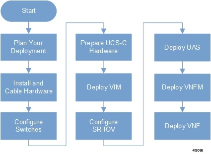
Deployment Workflow
The documentation set for this product strives to use bias-free language. For the purposes of this documentation set, bias-free is defined as language that does not imply discrimination based on age, disability, gender, racial identity, ethnic identity, sexual orientation, socioeconomic status, and intersectionality. Exceptions may be present in the documentation due to language that is hardcoded in the user interfaces of the product software, language used based on RFP documentation, or language that is used by a referenced third-party product. Learn more about how Cisco is using Inclusive Language.
Ultra M is a multi-product solution. Detailed instructions for installing each of these products is beyond the scope of this document. Instead, the sections that follow identify the specific, non-default parameters that must be configured through the installation and deployment of those products in order to deploy the entire solution.
Before deploying the Ultra M solution, it is very important to develop and plan your deployment.
Networking Overview provides a general overview and identifies basic requirements for networking the Ultra M solution.
With this background, use the tables in Network Definitions (Layer 2 and 3) to help plan the details of your network configuration.
This section describes the procedure to install all the components included in the Ultra M Solution.
To ensure hardware components of the Ultra M solution are installed properly, refer to the installation guides for the respective hardware components.
Catalyst 2960-XR Switch — http://www.cisco.com/c/en/us/td/docs/switches/lan/catalyst2960xr/hardware/installation/guide/b_c2960xr_hig.html
Catalyst 3850 48T-S Switch — http://www.cisco.com/c/en/us/td/docs/switches/lan/catalyst3850/hardware/installation/guide/b_c3850_hig.html
Nexus 93180-YC 48 Port — http://www.cisco.com/c/en/us/td/docs/switches/datacenter/nexus9000/hw/n93180ycex_hig/guide/b_n93180ycex_nxos_mode_hardware_install_guide.html
Nexus 9236C 36 Port — http://www.cisco.com/c/en/us/td/docs/switches/datacenter/nexus9000/hw/n9236c_hig/guide/b_c9236c_nxos_mode_hardware_install_guide.html
UCS C240 M4SX Server — http://www.cisco.com/c/en/us/td/docs/unified_computing/ucs/c/hw/C240M4/install/C240M4.html
Table 1 provides details for the recommended rack layout for the Hyper-converged Ultra M XS Single VNF deployment model.
|
Rack #1 |
Rack #2 |
|
|---|---|---|
|
RU-1 |
Empty |
Empty |
|
RU-2 |
Spine EOR Switch A: Nexus 9236C |
Spine EOR Switch B: Nexus 9236C |
|
RU-3 |
Empty |
Empty |
|
RU-4 |
VNF Mgmt Switch: Catalyst C3850-48T-S OR C2960XR-48TD |
Empty |
|
RU-5 |
VNF Leaf TOR Switch A: Nexus 93180YC-EX |
Empty |
|
RU-6 |
VNF Leaf TOR Switch B: Nexus 93180YC-EX |
Empty |
|
RU-7/8 |
Ultra UEM 1A: UCS C240 M4 SFF |
Empty |
|
RU-9/10 |
Ultra UEM 1B: UCS C240 M4 SFF |
Empty |
|
RU-11/12 |
Empty |
Empty |
|
RU-13/14 |
Demux SF: UCS C240 M4 SFF |
Empty |
|
RU-15/16 |
Standby SF: UCS C240 M4 SFF |
Empty |
|
RU-17/18 |
Active SF 1: UCS C240 M4 SFF |
Empty |
|
RU-19/20 |
Active SF 2: UCS C240 M4 SFF |
Empty |
|
RU-21/22 |
Active SF 3: UCS C240 M4 SFF |
Empty |
|
RU-23/24 |
Active SF 4: UCS C240 M4 SFF |
Empty |
|
RU-25/26 |
Active SF 5: UCS C240 M4 SFF |
Empty |
|
RU-27/28 |
Active SF 6: UCS C240 M4 SFF |
Empty |
|
RU-29/30 |
Empty |
Empty |
|
RU-31/32 |
Empty |
Empty |
|
RU-33/34 |
Empty |
Empty |
|
RU-35/36 |
Ultra UEM 1C |
OpenStack Control C: UCS C240 M4 SFF |
|
RU-37/38 |
Ultra M Manager: UCS C240 M4 SFF |
Empty |
|
RU-39/40 |
OpenStack Control A: UCS C240 M4 SFF |
OpenStack Control B: UCS C240 M4 SFF |
|
RU-41/42 |
Empty |
Empty |
|
Cables |
Controller Rack Cables |
Controller Rack Cables |
|
Cables |
Spine Uplink/Interconnect Cables |
Spine Uplink/Interconnect Cables |
|
Cables |
Leaf TOR To Spine Uplink Cables |
Empty |
|
Cables |
VNF Rack Cables |
Empty |
Table 1 provides details for the recommended rack layout for the Hyper-converged Ultra M XS Multi-VNF deployment model.
|
Rack #1 |
Rack #2 |
Rack #3 |
Rack #4 |
|
|---|---|---|---|---|
|
RU-1 |
Empty |
Empty |
Empty |
Empty |
|
RU-2 |
Spine EOR Switch A: Nexus 9236C |
Spine EOR Switch B: Nexus 9236C |
Empty |
Empty |
|
RU-3 |
Empty |
Empty |
Empty |
Empty |
|
RU-4 |
VNF Mgmt Switch: Catalyst C3850-48T-S OR C2960XR-48TD |
VNF Mgmt Switch: Catalyst C3850-48T-S OR C2960XR-48TD |
VNF Mgmt Switch: Catalyst C3850-48T-S OR C2960XR-48TD |
VNF Mgmt Switch: Catalyst C3850-48T-S OR C2960XR-48TD |
|
RU-5 |
VNF Leaf TOR Switch A: Nexus 93180YC-EX |
VNF Leaf TOR Switch A: Nexus 93180YC-EX |
VNF Leaf TOR Switch A: Nexus 93180YC-EX |
VNF Leaf TOR Switch A: Nexus 93180YC-EX |
|
RU-6 |
VNF Leaf TOR Switch B: Nexus 93180YC-EX |
VNF Leaf TOR Switch B: Nexus 93180YC-EX |
VNF Leaf TOR Switch B: Nexus 93180YC-EX |
VNF Leaf TOR Switch B: Nexus 93180YC-EX |
|
RU-7/8 |
Ultra UEM 1A: UCS C240 M4 SFF |
Ultra UEM 2A: UCS C240 M4 SFF |
Ultra UEM 3A: UCS C240 M4 SFF |
Ultra UEM 4A: UCS C240 M4 SFF |
|
RU-9/10 |
Ultra UEM 1B: UCS C240 M4 SFF |
Ultra UEM 2B: UCS C240 M4 SFF |
Ultra UEM 3B: UCS C240 M4 SFF |
Ultra UEM 4B: UCS C240 M4 SFF |
|
RU-11/12 |
Empty |
Empty |
Empty |
Empty |
|
RU-13/14 |
Demux SF: UCS C240 M4 SFF |
Demux SF: UCS C240 M4 SFF |
Demux SF: UCS C240 M4 SFF |
Demux SF: UCS C240 M4 SFF |
|
RU-15/16 |
Standby SF: UCS C240 M4 SFF |
Standby SF: UCS C240 M4 SFF |
Standby SF: UCS C240 M4 SFF |
Standby SF: UCS C240 M4 SFF |
|
RU-17/18 |
Active SF 1: UCS C240 M4 SFF |
Active SF 1: UCS C240 M4 SFF |
Active SF 1: UCS C240 M4 SFF |
Active SF 1: UCS C240 M4 SFF |
|
RU-19/20 |
Active SF 2: UCS C240 M4 SFF |
Active SF 2: UCS C240 M4 SFF |
Active SF 2: UCS C240 M4 SFF |
Active SF 2: UCS C240 M4 SFF |
|
RU-21/22 |
Active SF 3: UCS C240 M4 SFF |
Active SF 3: UCS C240 M4 SFF |
Active SF 3: UCS C240 M4 SFF |
Active SF 3: UCS C240 M4 SFF |
|
RU-23/24 |
Active SF 4: UCS C240 M4 SFF |
Active SF 4: UCS C240 M4 SFF |
Active SF 4: UCS C240 M4 SFF |
Active SF 4: UCS C240 M4 SFF |
|
RU-25/26 |
Active SF 5: UCS C240 M4 SFF |
Active SF 5: UCS C240 M4 SFF |
Active SF 5: UCS C240 M4 SFF |
Active SF 5: UCS C240 M4 SFF |
|
RU-27/28 |
Active SF 6: UCS C240 M4 SFF |
Active SF 6: UCS C240 M4 SFF |
Active SF 6: UCS C240 M4 SFF |
Active SF 6: UCS C240 M4 SFF |
|
RU-29/30 |
Empty |
Empty |
Empty |
Empty |
|
RU-31/32 |
Empty |
Empty |
Empty |
Empty |
|
RU-33/34 |
Empty |
Empty |
Empty |
Empty |
|
RU-35/36 |
Ultra UEM 1C,2C,3C,4C |
OpenStack Control C: UCS C240 M4 SFF |
Empty |
Empty |
|
RU-37/38 |
Ultra M Manager: UCS C240 M4 SFF |
Empty |
Empty |
Empty |
|
RU-39/40 |
OpenStack Control A: UCS C240 M4 SFF |
OpenStack Control B: UCS C240 M4 SFF |
Empty |
Empty |
|
RU-41/42 |
Empty |
Empty |
Empty |
Empty |
|
Cables |
Controller Rack Cables |
Controller Rack Cables |
Controller Rack Cables |
Empty |
|
Cables |
Spine Uplink/Interconnect Cables |
Spine Uplink/Interconnect Cables |
Empty |
Empty |
|
Cables |
Leaf TOR To Spine Uplink Cables |
Leaf TOR To Spine Uplink Cables |
Leaf TOR To Spine Uplink Cables |
Leaf TOR To Spine Uplink Cables |
|
Cables |
VNF Rack Cables |
VNF Rack Cables |
VNF Rack Cables |
VNF Rack Cables |
After the hardware has been installed, install all power and network cabling for the hardware using the information and instructions in the documentation for the specific hardware product. Refer to Related Documentation for links to the hardware product documentation. Ensure that you install your network cables according to your network plan.
All of the switches must be configured according to your planned network specifications.
 Note |
Refer to Network Planning for information and consideration for planning your network. |
Refer to the user documentation for each of the switches for configuration information and instructions:
Catalyst C2960XR-48TD-I: http://www.cisco.com/c/en/us/support/switches/catalyst-2960xr-48td-i-switch/model.html
Catalyst 3850 48T-S: http://www.cisco.com/c/en/us/support/switches/catalyst-3850-48t-s-switch/model.html
Nexus 93180-YC-EX: http://www.cisco.com/c/en/us/support/switches/nexus-93180yc-fx-switch/model.html
Nexus 9236C: http://www.cisco.com/c/en/us/support/switches/nexus-9236c-switch/model.html
UCS-C hardware preparation is performed through the Cisco Integrated Management Controller (CIMC). The tables in the following sections list the non-default parameters that must be configured per server type:
Refer to the UCS C-series product documentation for more information:
UCS C-Series Hardware — https://www.cisco.com/c/en/us/support/servers-unified-computing/ucs-c240-m4-rack-server/model.html
Important |
Part of the UCS server preparation is the configuration of virtual drives. If there are virtual drives present which need to be deleted, select the Virtual Drive Info tab, select the virtual drive you wish to delete, then click Delete Virtual Drive. Refer to the CIMC documentation for more information. |
Important |
The information in this section assumes that the server hardware was properly installed per the information and instructions in Install and Cable the Hardware. |
|
Parameters and Settings |
Description |
|---|---|
|
CIMC Utility Setup |
|
|
Enable IPV4 Dedicated No redundancy IP address Subnet mask Gateway address DNS address |
Configures parameters for the dedicated management port. |
|
Admin > User Management |
|
|
Username Password |
Configures administrative user credentials for accessing the CIMC utility. |
|
Admin > Communication Services |
|
|
IPMI over LAN Properties = Enabled |
Enables the use of Intelligent Platform Management Interface capabilities over the management port. |
|
Server > BIOS > Configure BIOS > Advanced |
|
|
Intel(R) Hyper-Threading Technology = Disabled |
Disable hyper-threading on server CPUs to optimize Ultra M system performance. |
|
Storage > Cisco 12G SAS Modular RAID Controller > Physical Drive Info |
|
|
Status = Unconfigured Good |
Ensures that the hardware is ready for use. |
|
Parameters and Settings |
Description |
|---|---|
|
CIMC Utility Setup |
|
|
Enable IPV4 Dedicated No redundancy IP address Subnet mask Gateway address DNS address |
Configures parameters for the dedicated management port. |
|
Admin > User Management |
|
|
Username Password |
Configures administrative user credentials for accessing the CIMC utility. |
|
Admin > Communication Services |
|
|
IPMI over LAN Properties = Enabled |
Enables the use of Intelligent Platform Management Interface capabilities over the management port. |
|
Admin > Communication Services |
|
|
IPMI over LAN Properties = Enabled |
Enables the use of Intelligent Platform Management Interface capabilities over the management port. |
|
Server > BIOS > Configure BIOS > Advanced |
|
|
Intel(R) Hyper-Threading Technology = Disabled |
Intel(R) Hyper-Threading Technology = Disabled |
|
Storage > Cisco 12G SAS Modular RAID Controller > Physical Drive Info |
|
|
Status = Unconfigured Good |
Ensures that the hardware is ready for use. |
|
Storage > Cisco 12G SAS Modular RAID Controller > Controller Info |
|
|
Virtual Drive Name = OS Read Policy = No Read Ahead RAID Level = RAID 1 Cache Policy: Direct IO Strip Size: 64KB Disk Cache Policy: Unchanged Access Policy: Read Write Size: 1143455 MB Write Policy: Write Through |
Creates the virtual drives required for use by the operating system (OS). |
|
Storage > Cisco 12G SAS Modular RAID Controller > Virtual Drive Info |
|
|
Initialize Type = Fast Initialize |
Initializes this virtual drive. A fast initialization quickly writes zeroes to the first and last 10-MB regions of the new virtual drive and completes the initialization in the background. |
|
Parameters and Settings |
Description |
|
|---|---|---|
|
CIMC Utility Setup |
||
|
Enable IPV4 Dedicated No redundancy IP address Subnet mask Gateway address DNS address |
Configures parameters for the dedicated management port. |
|
|
Admin > User Management |
||
|
Username Password |
Configures administrative user credentials for accessing the CIMC utility. |
|
|
Admin > Communication Services |
||
|
IPMI over LAN Properties = Enabled |
Enables the use of Intelligent Platform Management Interface capabilities over the management port. |
|
|
Server > BIOS > Configure BIOS > Advanced |
||
|
Intel(R) Hyper-Threading Technology = Disabled |
Intel(R) Hyper-Threading Technology = Disabled |
|
|
Storage > Cisco 12G SAS Modular RAID Controller > Physical Drive Info |
||
|
Status = Unconfigured Good |
Ensures that the hardware is ready for use. |
|
|
Storage > Cisco 12G SAS Modular RAID Controller > Controller Info |
||
|
Virtual Drive Name = BOOTOS Read Policy = No Read Ahead RAID Level = RAID 1 Cache Policy: Direct IO Strip Size: 64KB Disk Cache Policy: Unchanged Access Policy: Read Write Size: 1143455 MB Write Policy: Write Through |
Creates the virtual drives required for use by the operating system (OS). |
|
|
Storage > Cisco 12G SAS Modular RAID Controller > Virtual Drive Info, BOOTOS |
||
|
Initialize Type = Fast Initialize |
Initializes this virtual drive. A fast initialization quickly writes zeroes to the first and last 10-MB regions of the new virtual drive and completes the initialization in the background. |
|
|
Set as Boot Drive |
Sets the BOOTOS virtual drive as the system boot drive. |
|
Note |
OSD Compute Nodes are only used in Hyper-converged Ultra M models as described in UCS C-Series Servers. |
|
Parameters and Settings |
Description |
|||
|---|---|---|---|---|
|
CIMC Utility Setup |
||||
|
Enable IPV4 Dedicated No redundancy IP address Subnet mask Gateway address DNS address |
Configures parameters for the dedicated management port. |
|||
|
Admin > User Management |
||||
|
Username Password |
Configures administrative user credentials for accessing the CIMC utility. |
|||
|
Admin > Communication Services |
||||
|
IPMI over LAN Properties = Enabled |
Enables the use of Intelligent Platform Management Interface capabilities over the management port. |
|||
|
Server > BIOS > Configure BIOS > Advanced |
||||
|
Intel(R) Hyper-Threading Technology = Disabled |
Intel(R) Hyper-Threading Technology = Disabled |
|||
|
Storage > Cisco 12G SAS Modular RAID Controller > Physical Drive Info |
||||
|
Status = Unconfigured Good |
Ensures that the hardware is ready for use. |
|||
|
SLOT-HBA Physical Drive Numbers = 1 2 3 7 8 9 10 |
Ensure the UCS slot host-bus adapter for the drives are configured accordingly. |
|||
|
Storage > Cisco 12G SAS Modular RAID Controller > Physical Drive Number = 1 |
||||
|
Virtual Drive Name = BOOTOS Read Policy = No Read Ahead RAID Level = RAID 1 Cache Policy: Direct IO Strip Size: 64KB Disk Cache Policy: Unchanged Access Policy: Read Write Size: 285148 MB Write Policy: Write Through |
Creates a virtual drive leveraging the storage space available to physical drive number 1.
|
|||
|
Storage > Cisco 12G SAS Modular RAID Controller > Virtual Drive Info, BOOTOS, Physical Drive Number = 1 |
||||
|
Initialize Type = Fast Initialize |
Initializes this virtual drive. A fast initialization quickly writes zeroes to the first and last 10-MB regions of the new virtual drive and completes the initialization in the background. |
|||
|
Set as Boot Drive |
Sets the BOOTOS virtual drive as the system boot drive. |
|||
|
Storage > Cisco 12G SAS Modular RAID Controller > Physical Drive Number = 2 |
||||
|
Virtual Drive Name = BOOTOS Read Policy = No Read Ahead RAID Level = RAID 1 Cache Policy: Direct IO Strip Size: 64KB Disk Cache Policy: Unchanged Access Policy: Read Write Size: 285148 MB Write Policy: Write Through |
Creates a virtual drive leveraging the storage space available to physical drive number 2.
|
|||
|
Storage > Cisco 12G SAS Modular RAID Controller > Virtual Drive Info, BOOTOS, Physical Drive Number = 2 |
||||
|
Initialize Type = Fast Initialize |
Initializes this virtual drive. A fast initialization quickly writes zeroes to the first and last 10-MB regions of the new virtual drive and completes the initialization in the background. |
|||
|
Set as Boot Drive |
Sets the BOOTOS virtual drive as the system boot drive. |
|||
|
Storage > Cisco 12G SAS Modular RAID Controller > Physical Drive Number = 3 |
||||
|
Virtual Drive Name = JOURNAL Read Policy = No Read Ahead RAID Level = RAID 0 Cache Policy: Direct IO Strip Size: 64KB Disk Cache Policy: Unchanged Access Policy: Read Write Size: 456809 MB Write Policy: Write Through |
Creates a virtual drive leveraging the storage space available to physical drive number 3. |
|||
|
Storage > Cisco 12G SAS Modular RAID Controller > Virtual Drive Info, JOURNAL, Physical Drive Number = 3 |
||||
|
Initialize Type = Fast Initialize |
Initializes this virtual drive. A fast initialization quickly writes zeroes to the first and last 10-MB regions of the new virtual drive and completes the initialization in the background. |
|||
|
Storage > Cisco 12G SAS Modular RAID Controller > Physical Drive Number = 7 |
||||
|
Virtual Drive Name = OSD1 Read Policy = No Read Ahead RAID Level = RAID 0 Cache Policy: Direct IO Strip Size: 64KB Disk Cache Policy: Unchanged Access Policy: Read Write Size: 1143455 MB Write Policy: Write Through |
Creates a virtual drive leveraging the storage space available to physical drive number 7. |
|||
|
Storage > Cisco 12G SAS Modular RAID Controller > Virtual Drive Info, OSD1, Physical Drive Number = 7 |
||||
|
Initialize Type = Fast Initialize |
Initializes this virtual drive. A fast initialization quickly writes zeroes to the first and last 10-MB regions of the new virtual drive and completes the initialization in the background. |
|||
|
Storage > Cisco 12G SAS Modular RAID Controller > Physical Drive Number = 8 |
||||
|
Virtual Drive Name = OSD2 Read Policy = No Read Ahead RAID Level = RAID 0 Cache Policy: Direct IO Strip Size: 64KB Disk Cache Policy: Unchanged Access Policy: Read Write Size: 1143455 MB Write Policy: Write Through |
Creates a virtual drive leveraging the storage space available to physical drive number 8. |
|||
|
Storage > Cisco 12G SAS Modular RAID Controller > Virtual Drive Info, OSD2, Physical Drive Number = 8 |
||||
|
Initialize Type = Fast Initialize |
Initializes this virtual drive. A fast initialization quickly writes zeroes to the first and last 10-MB regions of the new virtual drive and completes the initialization in the background. |
|||
|
Storage > Cisco 12G SAS Modular RAID Controller > Physical Drive Number = 9 |
||||
|
Virtual Drive Name = OSD3 Read Policy = No Read Ahead RAID Level = RAID 0 Cache Policy: Direct IO Strip Size: 64KB Disk Cache Policy: Unchanged Access Policy: Read Write Size: 1143455 MB Write Policy: Write Through |
Creates a virtual drive leveraging the storage space available to physical drive number 9. |
|||
|
Storage > Cisco 12G SAS Modular RAID Controller > Virtual Drive Info, OSD3, Physical Drive Number = 9 |
||||
|
Initialize Type = Fast Initialize |
Initializes this virtual drive. A fast initialization quickly writes zeroes to the first and last 10-MB regions of the new virtual drive and completes the initialization in the background. |
|||
|
Storage > Cisco 12G SAS Modular RAID Controller > Physical Drive Number = 10 |
||||
|
Virtual Drive Name = OSD4 Read Policy = No Read Ahead RAID Level = RAID 0 Cache Policy: Direct IO Strip Size: 64KB Disk Cache Policy: Unchanged Access Policy: Read Write Size: 1143455 MB Write Policy: Write Through |
Creates a virtual drive leveraging the storage space available to physical drive number 10. |
|||
|
Storage > Cisco 12G SAS Modular RAID Controller > Virtual Drive Info, OSD4, Physical Drive Number = 10 |
||||
|
Initialize Type = Fast Initialize |
Initializes this virtual drive. A fast initialization quickly writes zeroes to the first and last 10-MB regions of the new virtual drive and completes the initialization in the background. |
|||
Within the Ultra M solution, OpenStack Platform Director (OSP-D) functions as the virtual infrastructure manager (VIM).
The method by which the VIM is deployed depends on the architecture of your Ultra M model. Refer to the following section for information related to your deployment scenario.
Deploying the VIM for Hyper-Converged Ultra M Models is performed using an automated workflow enabled through software modules within Ultra Automation Services (UAS). These services leverage user-provided configuration information to automatically deploy the VIM Orchestrator (Undercloud) and the VIM (Overcloud).
For information on using this automated process, in the USP Deployment Automation Guide, refer to the Virtual Infrastructure Manager Installation Automation section.
After the OpenStack Undercloud (VIM Orchestrator) and Overcloud (VIM) have been successfully deployed on the Ultra M hardware, you must deploy the USP-based VNF.
This process is performed through the Ultra Automation Services (UAS). UAS is an automation framework consisting of a set of software modules used to automate the USP-based VNF deployment and related components such as the VNFM.
For detailed information on the automation workflow, refer to the Ultra Service Platform Deployment Automation Guide.
 Feedback