Technical specifications
System requirements
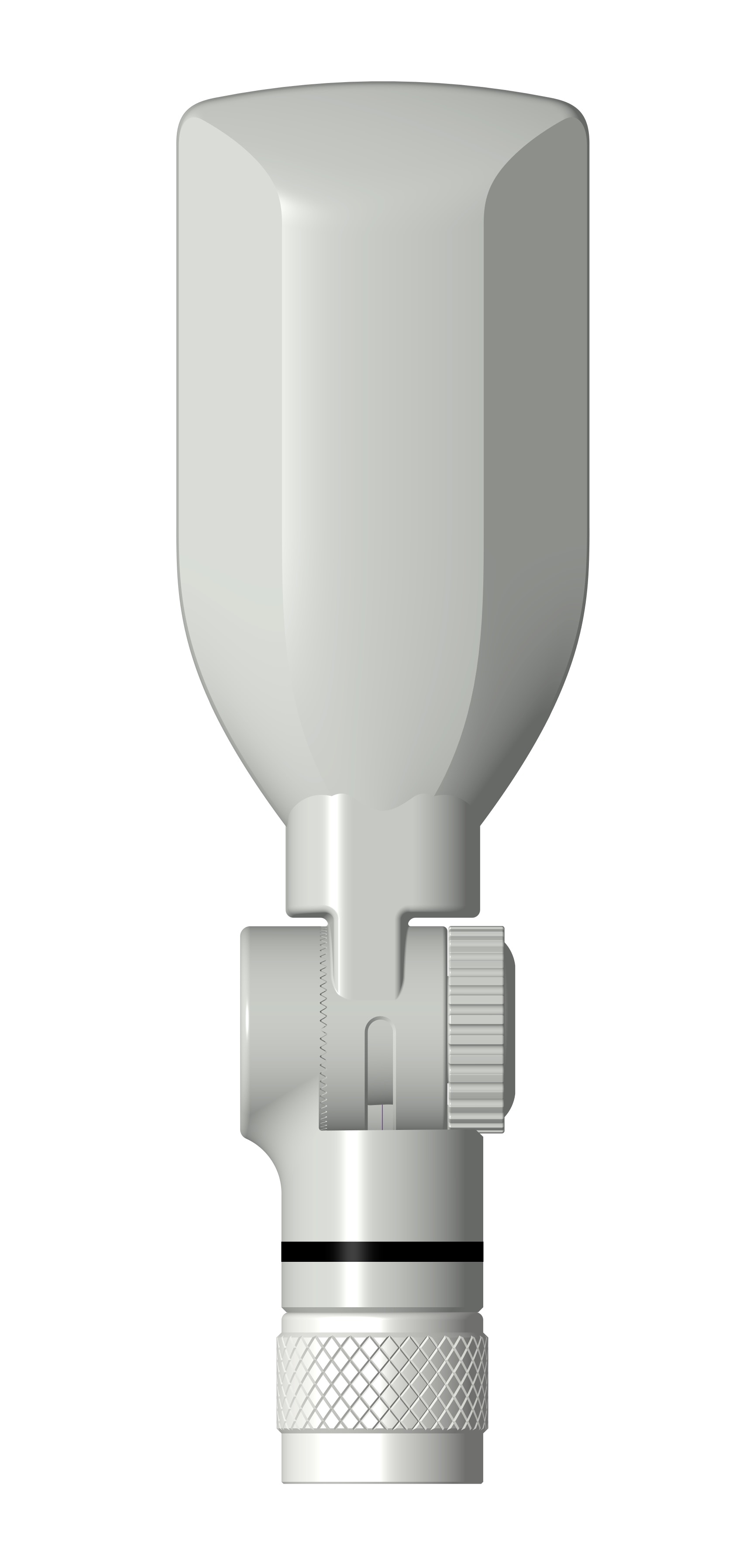
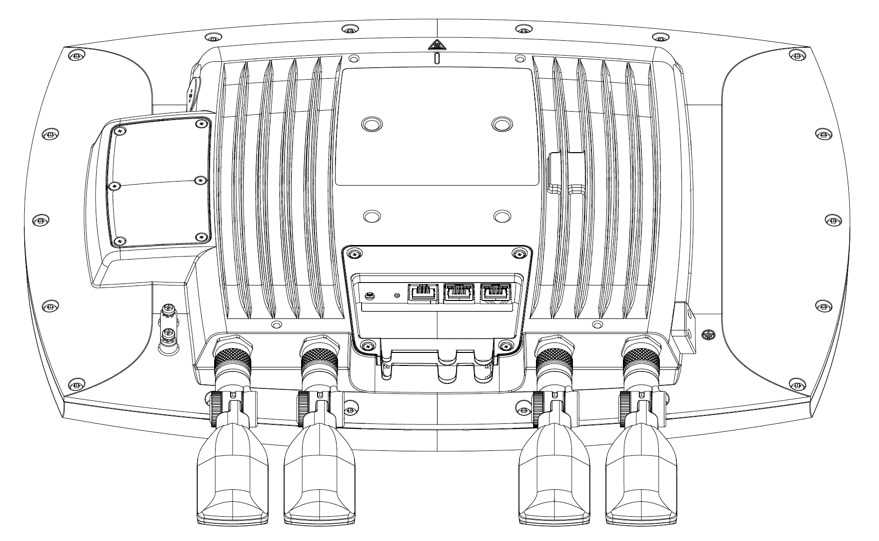
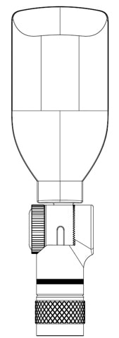
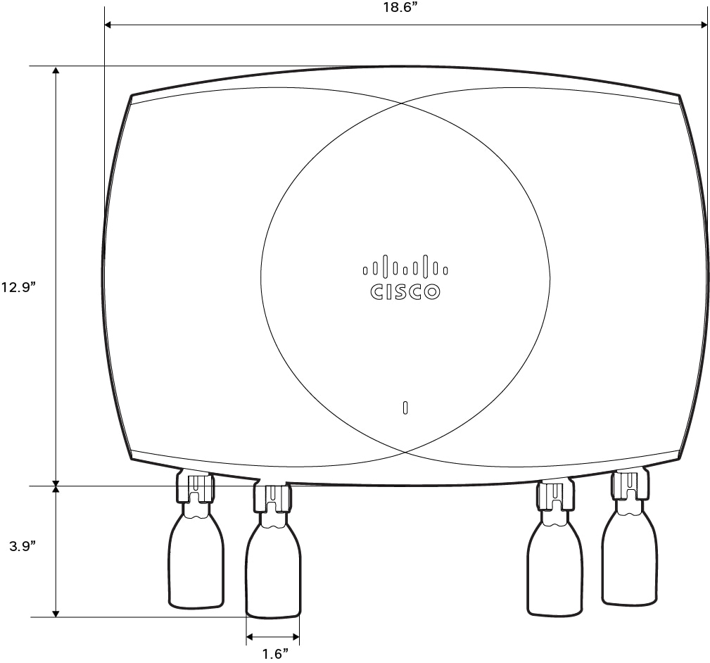
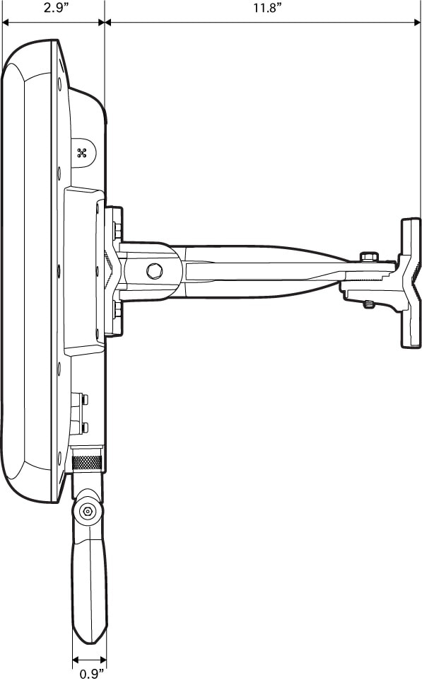
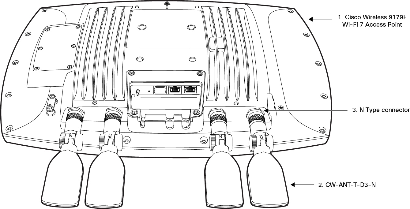
This antenna is designed for indoor and outdoor use with Cisco Wireless 9179F Wi-Fi 7 Access Point.
Antenna specifications
|
Parameters |
Descriptions |
|---|---|
|
Antenna type |
Directional |
|
SIA Functionality |
Available |
|
Nominal input impedance |
50 Ohms |
|
Polarization |
Linear |
|
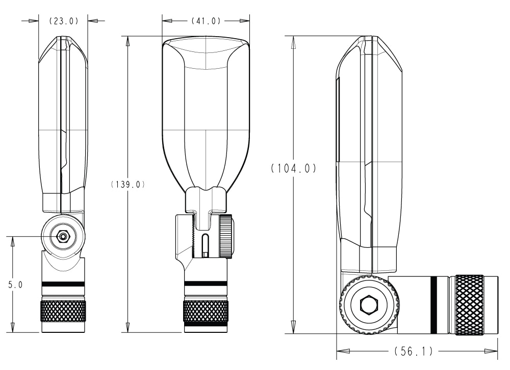
Length |
139mm |
|
Width |
41mm |
|
Depth (thickness) |
23mm |
|
Weight (without mount) |
0.161 lbs. (73 g) |
|
Connector type |
N-Type Male Connector |
|
Operating temperature range |
-40ºC to 65ºC -4° to 122°F (-20° to 50°C) including solar load. |
|
Environment rating |
IP66, IP67 |
|
Environmental sensors |
Supports air pressure sensors |
| Parameters | Value starting range | Value ending range |
|---|---|---|
|
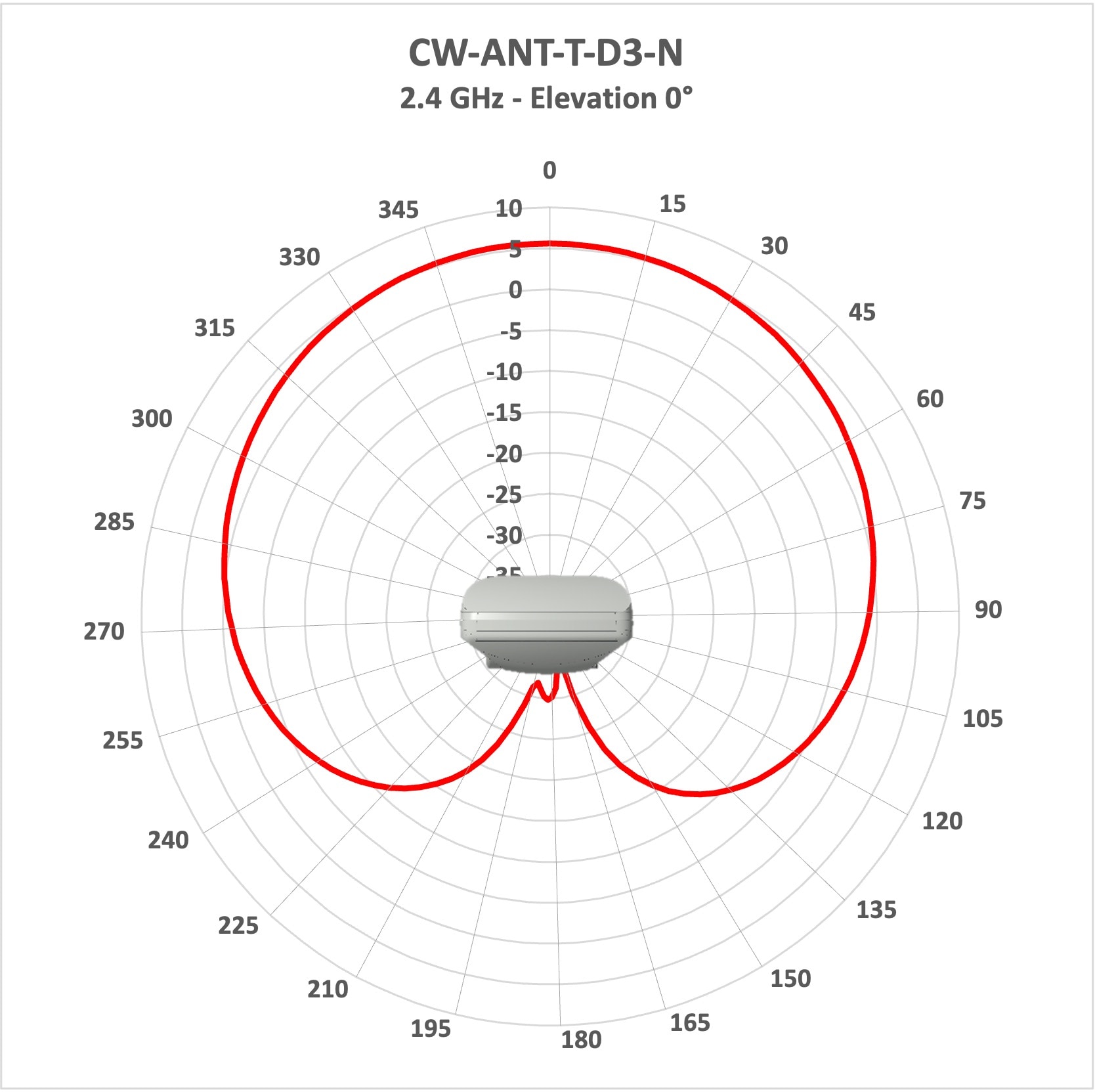
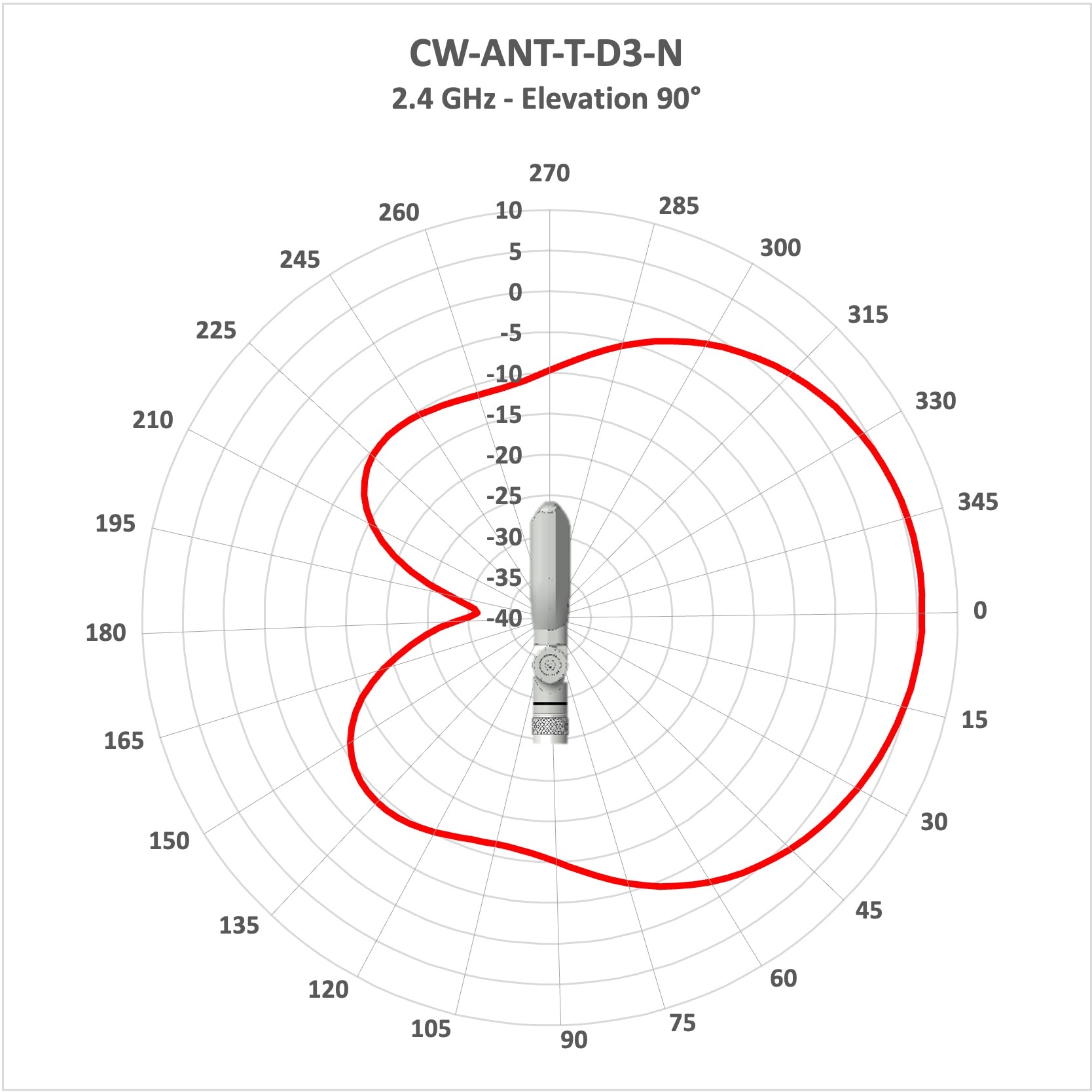
Operating frequency range |
2400–2500 MHz |
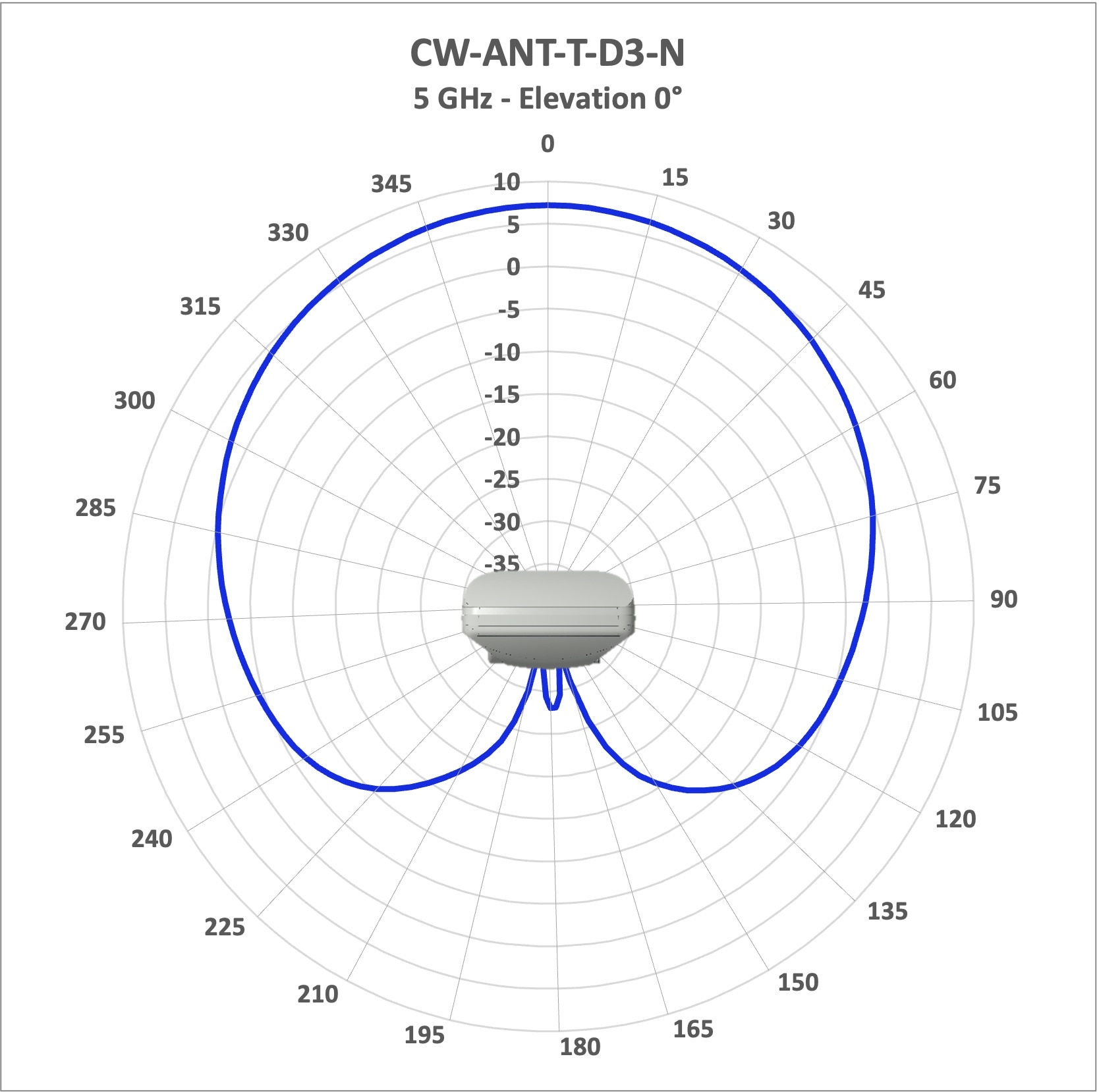
5180–7125 MHz |
|
Peak Gain (6dBi) |
2400 |
2500 |
|
Peak Gain (7.5dBi) |
5158 |
5900 |
|
Peak Gain (7.5dBi) |
6000 |
7125 |
|
Average Az Beamwidth |
2400-2500: 118 |
|
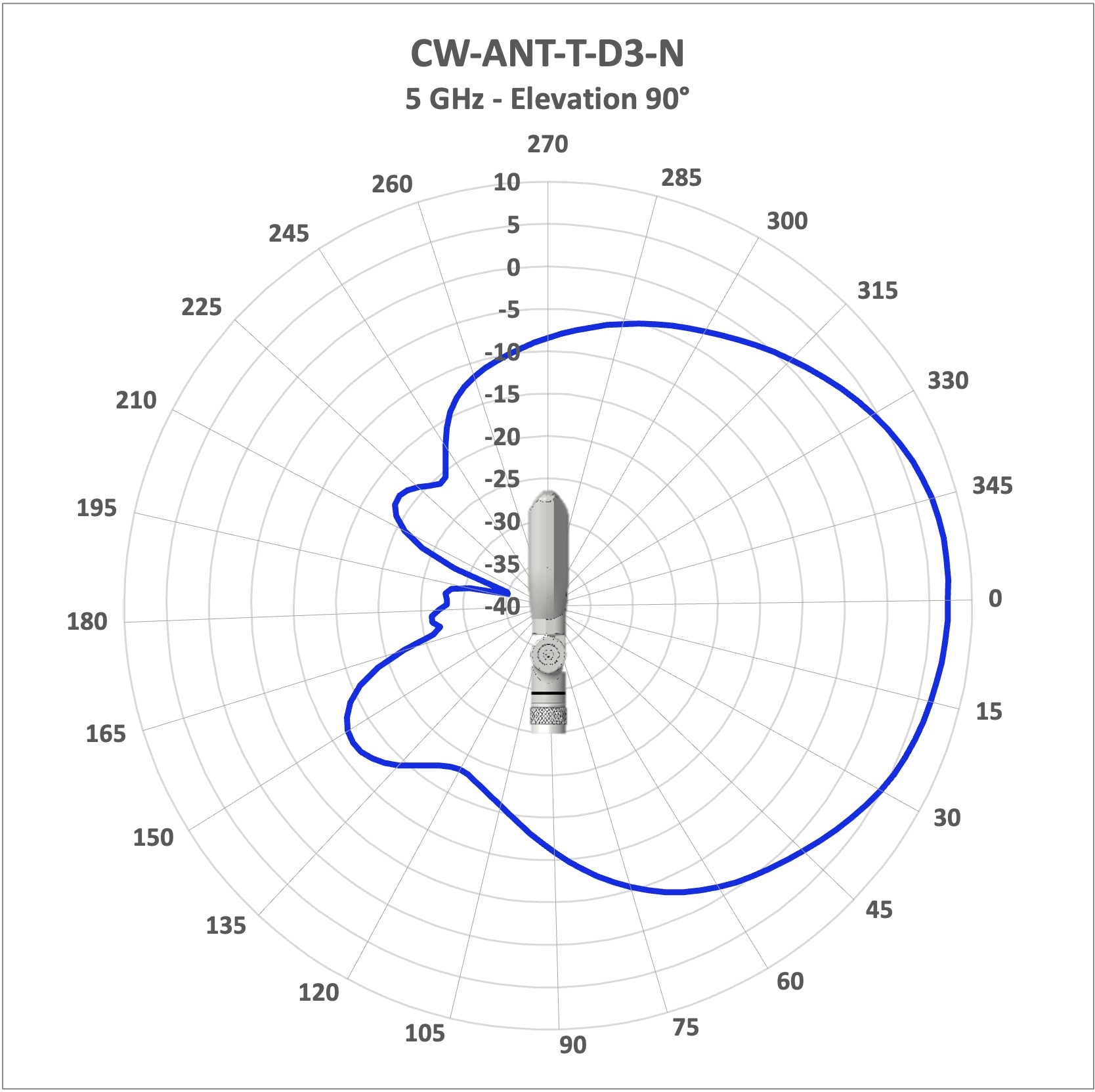
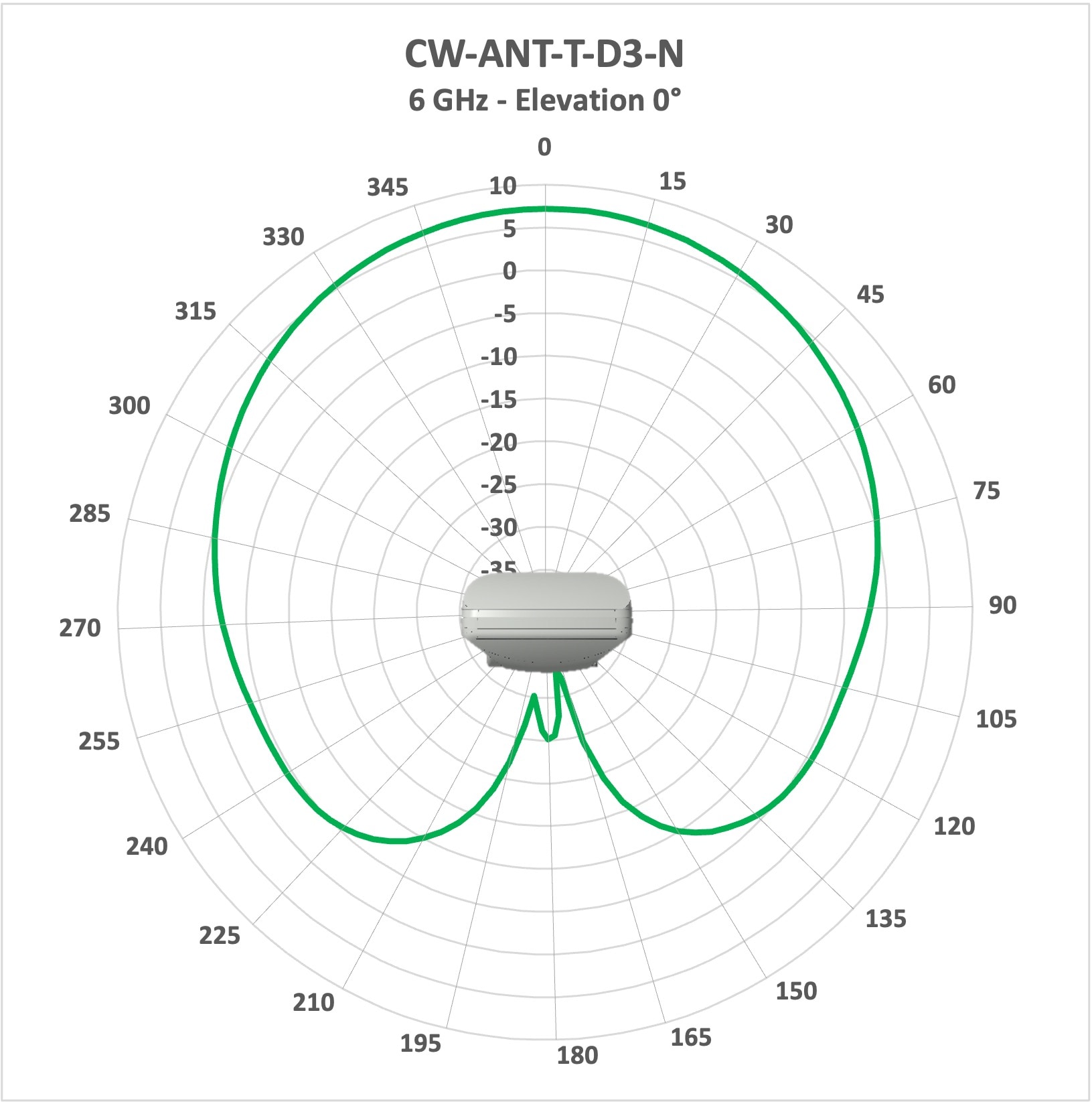
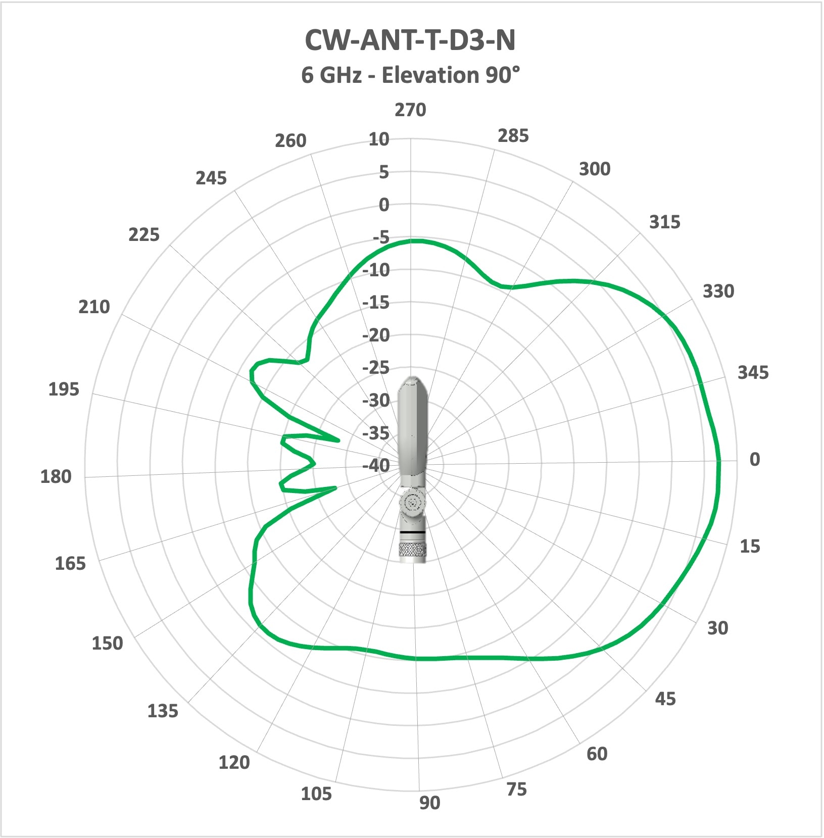
| Azimuth Plane 3-dB Beamwidth –V-Pol | 95° | 148° |
| Azimuth Plane 3-dB Beamwidth–H-Pol | 144° | 150° |
| Azimuth Plane 6-dB Beamwidth –V-Pol | 120° | 172° |
| Azimuth Plane 6-dB Beamwidth –H-Pol | 171° | 179° |
| Elevation Plane 3-dB Beamwidth–V-Pol | 44° | 30° |
| Elevation Plane 3-dB Beamwidth–H-Pol | 34° | 33° |
| VSWR | <2.0 | <2.0 |
| Front-to-back ratio (V-Pol) | > 20 dB | > 20 dB |
| Front-to-back ratio (H-Pol) | > 10 dB | > 10 dB |

 Feedback