About Cisco Aironet 2.4-GHz/5-GHz 8-dBi Directional Antenna (AIR-ANT2588P4M-NS)
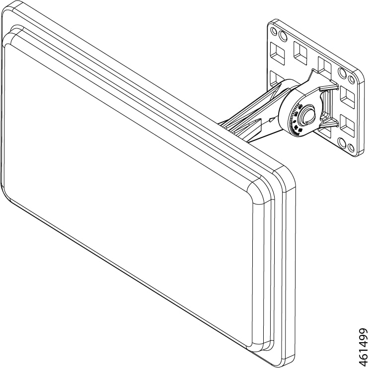
This describes the Cisco Aironet AIR-ANT2588P4M-N 2.4/5-GHz 4-port directional antenna with N-connectors, and provides specifications and mounting instructions. The antenna operates in both the 2.4 GHz and 5 GHz frequency bands and is designed for outdoor use. This antenna includes self-identifying circuitry.
Technical Specifications
|
Antenna type |
Dual-polarized directional antenna |
|
Nominal input impedance |
50 Ohms |
|
Polarization |
Vertical (2 ports), Horizontal (2 ports) |
|
Length |
12 in. (30.48 cm) |
|
Width |
7 in. (17.78 cm) |
|
Height |
1.0 in. (2.62 cm) |
|
Weight (without mount) |
1.54 lbs. (0.69 kg) |
|
Connector type |
N-Female Bulkhead (x4) |
|
Operating temperature range |
-22 to 158°F |
|
-30 to 70°C |
|
|
Environment rating |
IP67 |
| Operating frequency range | 2400–2500 MHz | 5150–5900 MHz |
| Peak Gain (dBi), V-Pol | 9.1 | 9.6 |
| Peak Gain (dBi), H-Pol | 7.1 | 7.8 |
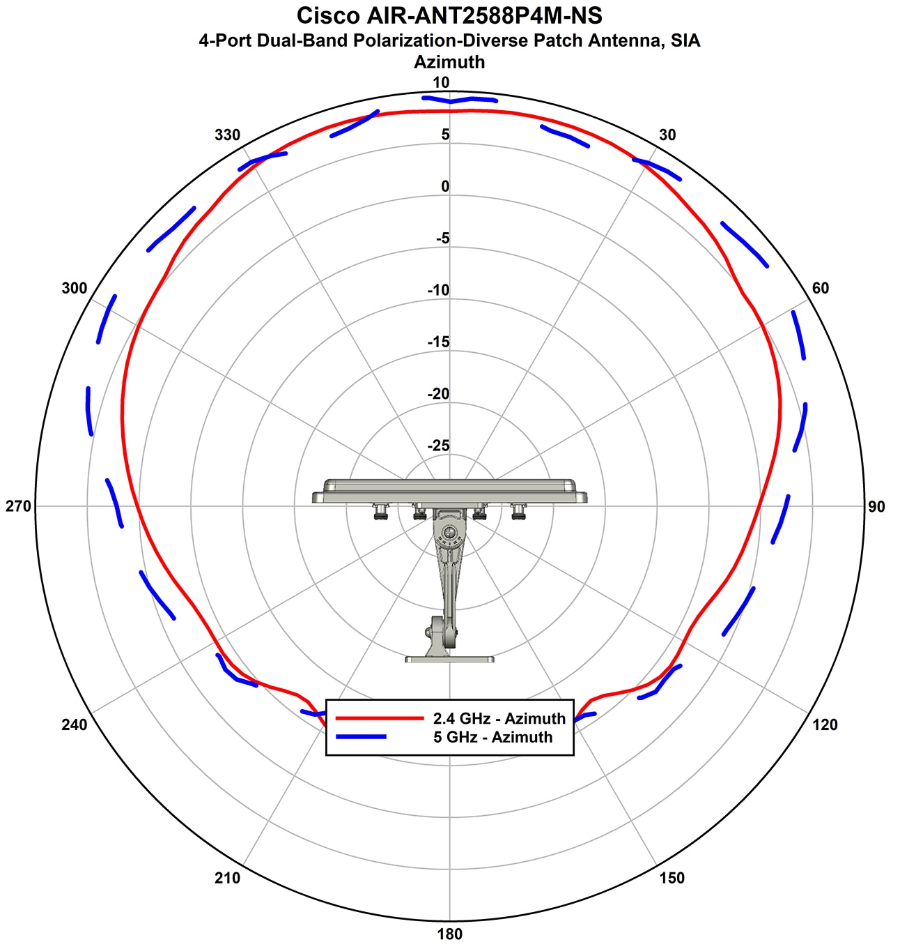
| Azimuth Plane 3-dB Beamwidth –V-Pol | 95° | 148° |
| Azimuth Plane 3-dB Beamwidth–H-Pol | 144° | 150° |
| Azimuth Plane 6-dB Beamwidth –V-Pol | 120° | 172° |
| Azimuth Plane 6-dB Beamwidth –H-Pol | 171° | 179° |
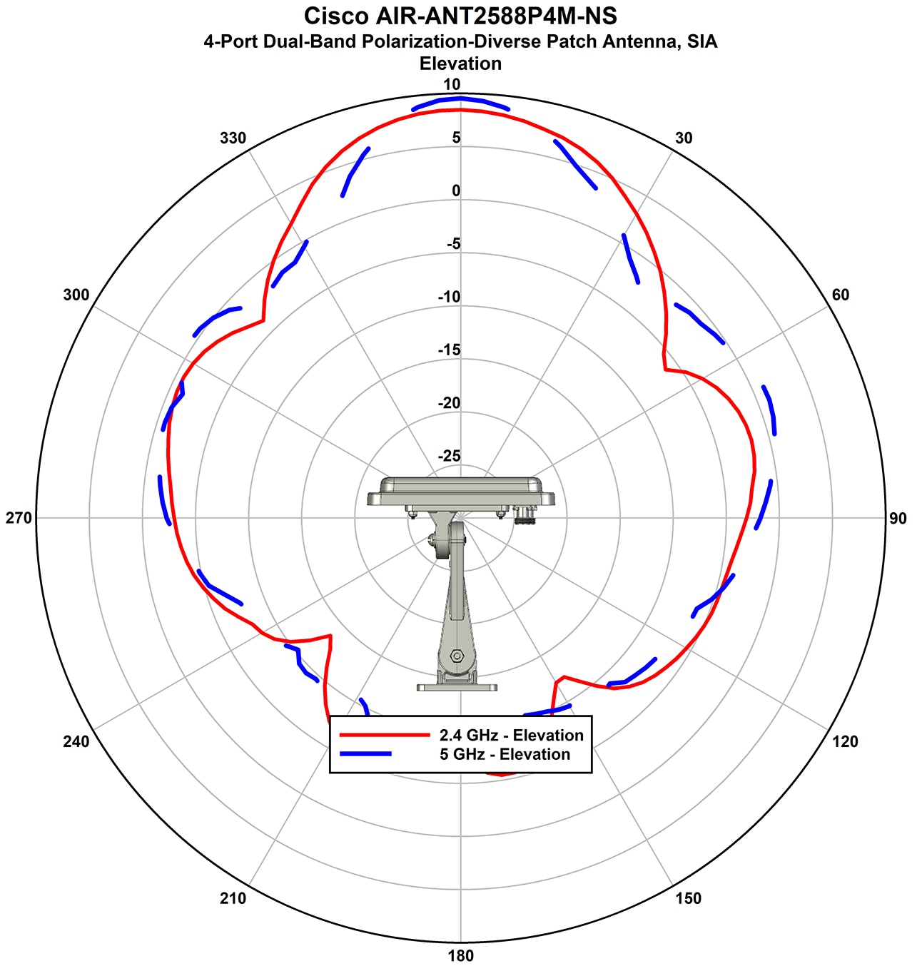
| Elevation Plane 3-dB Beamwidth–V-Pol | 44° | 30° |
| Elevation Plane 3-dB Beamwidth–H-Pol | 34° | 33° |
| VSWR | <2.0 | <2.0 |
| Front-to-back ratio (V-Pol) | > 20 dB | > 20 dB |
| Front-to-back ratio (H-Pol) | > 10 dB | > 10 dB |
System Requirements
This antenna is designed for indoor and outdoor use with any of the supported Cisco access points that requires four (4) dual-band antennas.
Azimuth and Elevation Radiation Patterns
Installing the Antenna
You can install the antenna on a pole from 1.63" to 2.3" pipe O.D. The mounting options allow the antenna to be vertically or horizontally polarized.
Safety Precautions
Translated versions of the following safety warnings are provided in the Safety Warnings for Cisco Aironet Antennas, which is available at http://www.cisco.com.
 Warning |
Installation of this antenna near power lines is dangerous. For your safety, follow the installation directions. |
Warning |
This warning symbol means danger. You are in a situation that could cause bodily injury. Before you work on any equipment, be aware of the hazards involved with electrical circuitry and be familiar with standard practices for preventing accidents. |
Warning |
In order to comply with international radio frequency (RF) exposure limits, dish antennas should be located at a minimum of 8.7 inches (22 cm) or more from the bodies of all persons. Other antennas should be located a minimum of 7.9 inches (20 cm) or more from the bodies of all persons. |
Warning |
Do not work on the system or connect or disconnect cables during periods of lightning activity. |
Warning |
This equipment must be grounded. Never defeat the ground conductor or operate the equipment in the absence of a suitably installed ground conductor. Contact the appropriate electrical inspection authority or an electrician if you are uncertain that suitable grounding is available. |
Warning |
Do not locate the antenna near overhead power lines or other electric light or power circuits, or where it can come into contact with such circuits. When installing the antenna, take extreme care not to come into contact with such circuits, as they may cause serious injury or death. For proper installation and grounding of the antenna, please refer to national and local codes (e.g. U.S.:NFPA 70, National Electrical Code, Article 810, in Canada: Canadian Electrical Code, Section 54). |
Each year hundreds of people are killed or injured when attempting to install an antenna. In many of these cases, the victim was aware of the danger of electrocution but did not take adequate steps to avoid the hazard.
For your safety, and to help you achieve a good installation, please read and follow these safety precautions. They may save your life!
-
If you are installing an antenna for the first time, for your own safety as well as others, seek professional assistance. Your Cisco sales representative can explain which mounting method to use for the size and type antenna you are about to install.
-
Select your installation site with safety as well as performance in mind. Remember, electric power lines and phone lines look alike. For your safety, assume that any overhead line can kill you.
-
Call your electric power company. Tell them your plans and ask them to come look at your proposed installation. This is a small inconvenience considering your life is at stake.
-
Plan your installation carefully and completely before you begin. Successful raising of a mast or tower is largely a matter of coordination. Each person should be assigned a specific task and should know what to do and when to do it. One person should be in charge of the operation to issue instructions and watch for signs of trouble.
-
When installing your antenna, remember:
-
Do not use a metal ladder.
-
Do not work on a wet or windy day.
-
Do dress properly: wear shoes with rubber soles and heels, rubber gloves, long sleeved shirt or jacket.
-
-
If the assembly starts to drop, get away from it and let it fall. Remember, the antenna, mast, cable, and metal guy wires are all excellent conductors of electrical current. Even the slightest touch of any of these parts to a power line completes an electrical path through the antenna and the installer: You!
-
If any part of the antenna system should come in contact with a power line, do not touch it or try to remove it yourself. Call your local power company. They will remove it safely.
-
If an accident occurs with the power lines, call for qualified emergency help immediately.
Installation Guidelines
Follow these guidelines to ensure the best possible performance:
Before you begin
Because the antennas transmit and receive radio signals, they are susceptible to RF obstructions and common sources of interference that can reduce throughput and range of the device to which they are connected.
Procedure
|
Step 1 |
Mount the antenna as high as possible to take advantage of its propagation characteristics. |
|
Step 2 |
Keep the antenna away from metal obstructions such as heating and air-conditioning ducts, large ceiling trusses, building superstructures, and major power cabling runs. If necessary, use a rigid conduit to lower the antenna away from these obstructions. |
|
Step 3 |
The density of the materials used in a building’s construction determines the number of walls the signal must pass through and still maintain adequate coverage. Consider the following before choosing the location in which to install your antenna:
|
|
Step 4 |
Install the antenna away from 5 GHz cordless phones. These products can cause signal interference because they operate in the same frequency range as the device your antenna is connected to. |
Site Selection
To determine a safe distance from wires, power lines, and trees:
Before you begin
Before attempting to install your antenna, determine where you can best place the antenna for safety and performance.
Procedure
|
Step 1 |
Measure the height of your antenna. |
||
|
Step 2 |
Add this length to the length of your tower or mast and then double this total for the minimum recommended safe distance.
|
What to do next
Generally, the higher an antenna is above the ground, the better it performs. Good practice is to install your antenna about 5 to 10 ft (1.5 to 3 m) above the roof line and away from all power lines and obstructions. If possible, find a mounting place directly above your wireless device so that the lead-in cable can be as short as possible.
Tools and Equipment Requirements
-
Antenna mount flange
-
Elevation adjustable flange
-
Azimuth adjustable flange
-
Two 1/4 in. 20 azimuth and elevation adjustment bolts and nuts with 1/4 in. flat washers and lock washers
-
Two pipe clamps
The following tools and equipment are not provided:
-
5/16 in wrench
-
1/4 in flat head screwdriver
-
5/16 in nut driver or flat head screwdriver for pipe clamps
Mounting on a Pole
To mount your antenna on a pole:
Procedure
|
Step 1 |
Remove antenna and mount kit from packaging. |
|
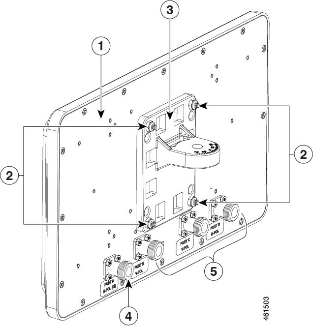
Step 2 |
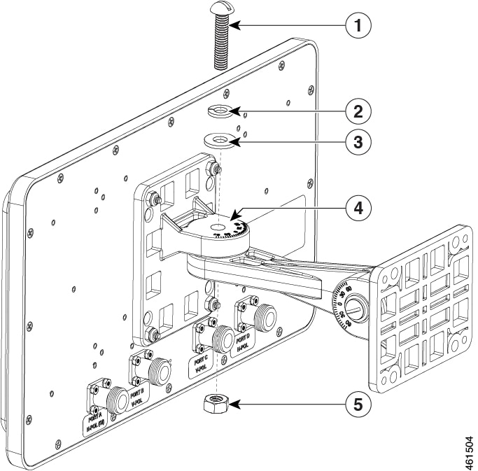
Attach antenna mount flange to the back of the antenna as shown applying a maximum nut-tightening torque of 12 in lbf (1.1 Nm). |
|
1 |
Antenna |
4 |
Port A (SIA supported) |
|
2 |
Stud nut |
5 |
Ports B, C, C (Non SIA) |
|
3 |
Antenna mount flange |
|
Step 3 |
Attach azimuth adjustable flange as shown and loosely secure hardware. |
|
1 |
Azimuth adjustable bolt |
4 |
Azimuth mount flange |
|
2 |
Lock washer |
5 |
Hex nut |
|
3 |
1/4-in. flat washer |
|
Step 4 |
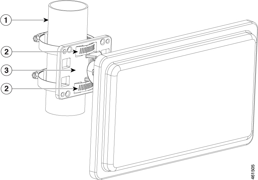
Attach elevation adjustable flange to pipe routing band clamps as shown. Tighten the pipe clamps to a torque of 35–45 in lbf (4.0–5.1 Nm). |
|
1 |
Pole/pipe |
2 |
Hose clamp |
|
3 |
Elevation mounting flange |
|
Step 5 |
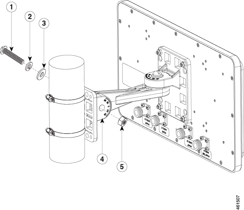
Attach the antenna assembly to the elevation adjustable flange on the pipe. |
|
1 |
Elevation adjustment bolt |
4 |
Elevation mount flange |
|
2 |
Lock washer |
5 |
Hex nut |
|
3 |
1/4-in. flat washer |
|
Step 6 |
Adjust the position of the antenna to the desired azimuth and elevation angles and tighten all pivot hardware (2 places) to a maximum torque of 30 in-lbf (3.4 Nm). The bracket allows the antenna position to be adjustable to +/–45 degrees azimuth and +/–60 degrees elevation.
|
Mounting on a Vertical Surface
To mount your antenna on a vertical surface:
Before you begin
The antenna can be wall mounted using the provided mounting bracket.
Procedure
|
Step 1 |
Remove antenna and mount kit from packaging. |
|
Step 2 |
Attach antenna mount flange to the back of the antenna as shown in Attaching Antenna Mount Flange, applying a maximum nut-tightening torque of 12 in. lbf (1.1 Nm). |
|
Step 3 |
Attach azimuth adjustable flange as shown in Attach Azimuth Adjustable Flange and loosely secure hardware. |
|
Step 4 |
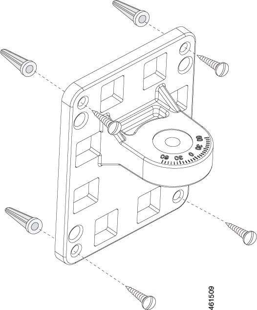
Using the provided anchors and screws, attach the azimuth adjustable flange to the wall as shown in Wall Mounting. |
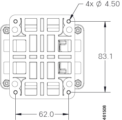
Distance Between Bracket Mounting Holes shows the distance between the bracket mounting holes in millimeters.
|
Step 5 |
Attach antenna assembly to azimuth bracket, as shown in Attaching Antenna Assembly. |
||
|
Step 6 |
Adjust the position of the antenna to the desired azimuth and elevation angles and tighten all pivot hardware (two places) to a maximum torque of 30 in. lbf (3.4 Nm). The bracket allows the antenna position to be adjustable to +/–45 degrees azimuth and +/–60 degrees elevation.
|
Antenna Cable Information
The antenna is to be used with supported Cisco access points. In Dual-Radio mode, the port-to-port designations are as follows: port A of the antenna must be connected to port 1 of the access point, port B of the antenna must be connected to port 2 of the access point, port C of the antenna must be connected to port 3 of the access point, and port D of the antenna must be connected to port 4 of the access point.
 Note |
Coaxial cable loses efficiency as the frequency increases, resulting in signal loss. The cable should be kept as short as possible, because cable length also determines the amount of signal loss (the longer the run, the greater the loss) |
Cisco offers low-loss 5 ft. and 10 ft. coaxial cables, parts AIR-CAB005LL-N and AIR-CAB010LL-N, respectively, for connection from the antenna to the access point. These cables have one straight male type-N connector and one right angle male type-N connector. To use all of the ports on the AIR-ANT2588P4M-N four cables will be needed.
After the cable is attached to the antenna, make sure that the connections are sealed (if outdoors) to prevent moisture and other weathering elements from affecting performance. Cisco recommends using a coax seal (such as CoaxSeal) for outdoor connections. Silicone sealant or electrical tape are not recommended for sealing outdoor connections.
Grounding the Antenna
Follow these steps to ground the antenna in accordance with national electrical code instructions.
Procedure
|
Step 1 |
Use No. 10 AWG copper or No. 8 or larger copper-clad steel or bronze wire as ground wires for both mast and lead-in. Securely clamp the wire to the bottom of the mast. |
||
|
Step 2 |
Secure the lead-in wire to an antenna discharge unit and the mast ground wire to the building with stand-off insulators spaced from 4 ft (1.2 m) to 8 ft (2.4 m) apart. |
||
|
Step 3 |
Mount the antenna discharge unit as close as possible to where the lead-in wire enters the building. |
||
|
Step 4 |
Drill a hole in the building’s wall as close as possible to the equipment to which you will connect the lead-in cable.
|
||
|
Step 5 |
Pull the cable through the hole and form a drip loop close to where it enters the building. |
||
|
Step 6 |
Thoroughly waterproof the lead-in area. |
||
|
Step 7 |
Install a lightning arrestor. |
||
|
Step 8 |
Connect the lead-in cable to the equipment. |
 Feedback