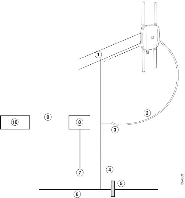
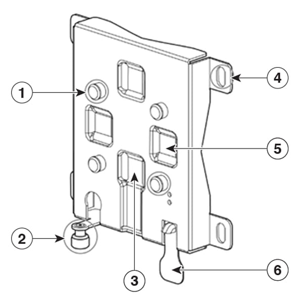
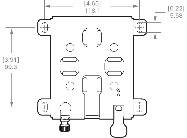
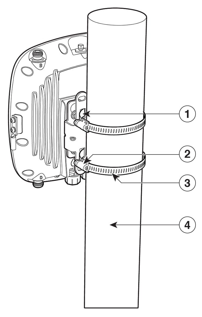
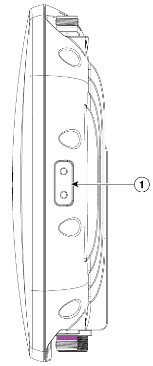
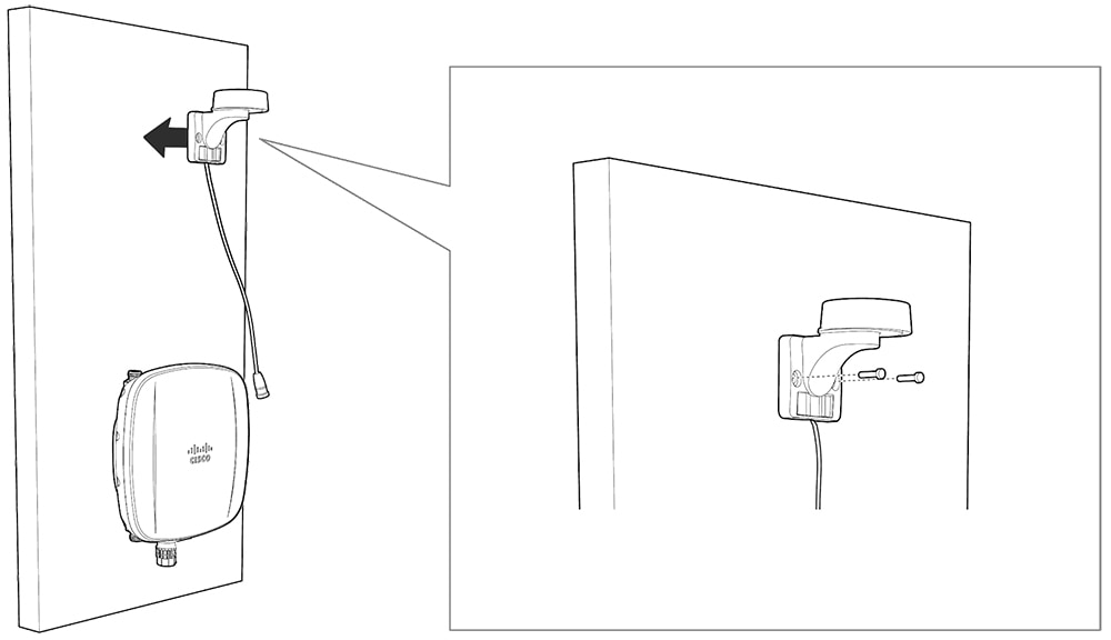
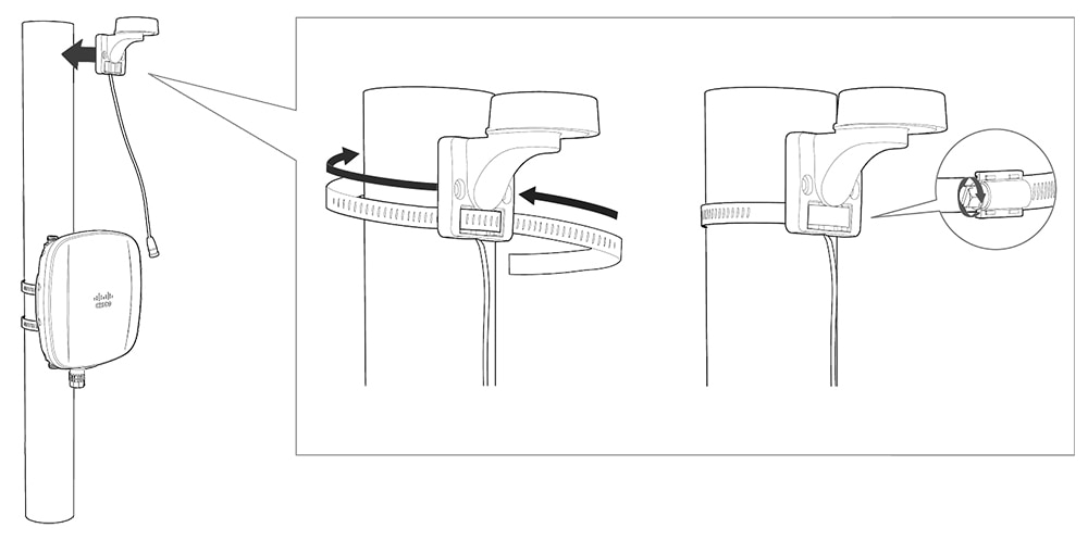
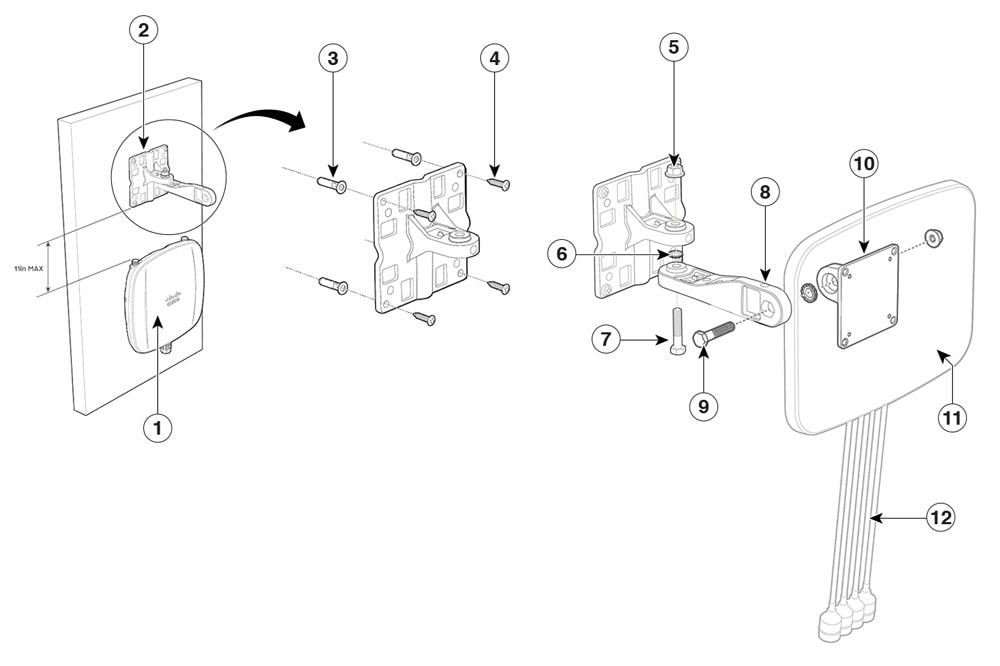
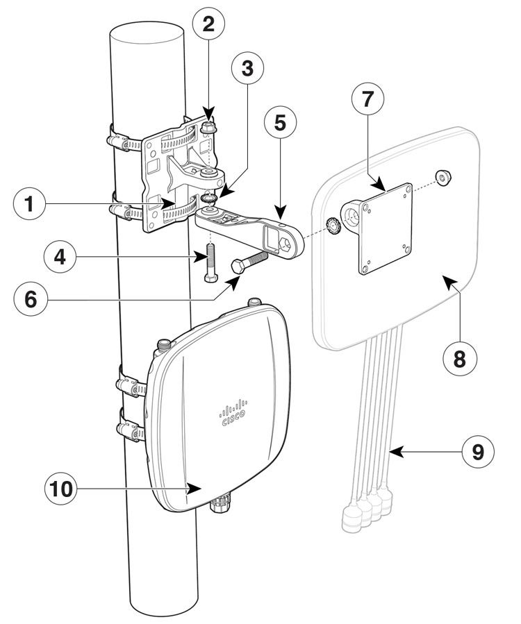
Installing the Access Point

Installing an AP involves the following high-level tasks:

Unpacking the Package

Package Contents

Each AP package contains the following items:

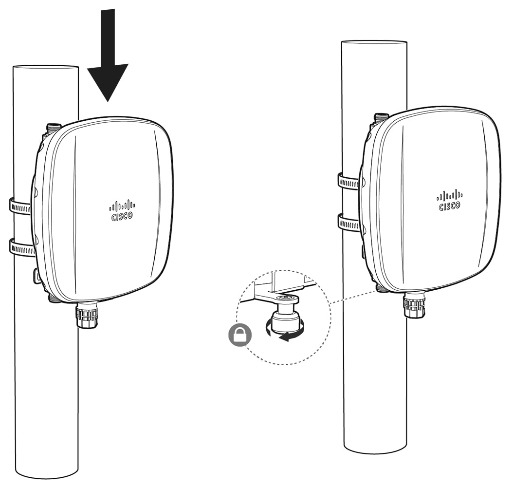
  • One CW9163E Outdoor AP

  • Ground lug and screws with lock washers

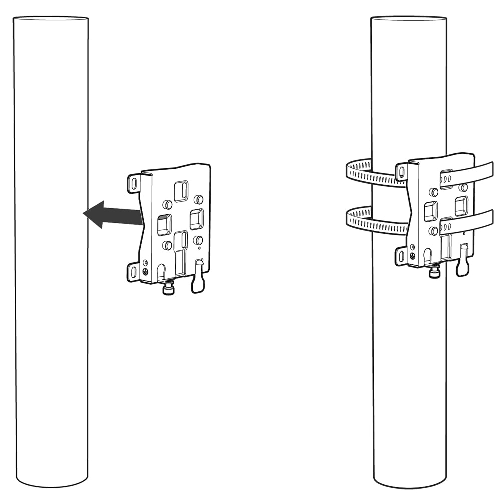
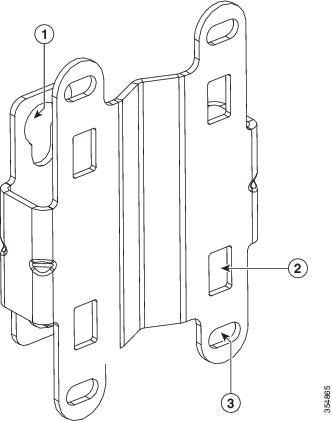
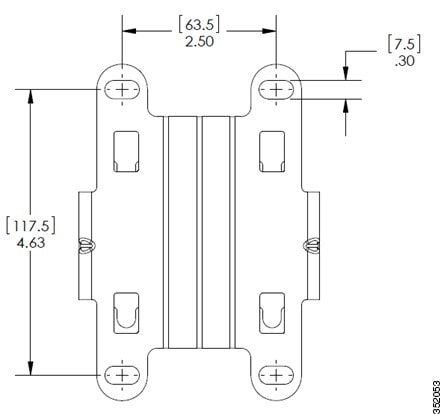
  • MA-MNT-MR-16 mounting plate

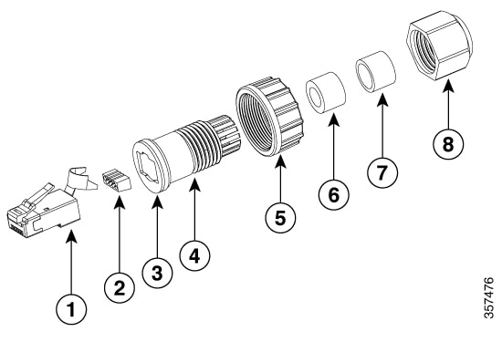
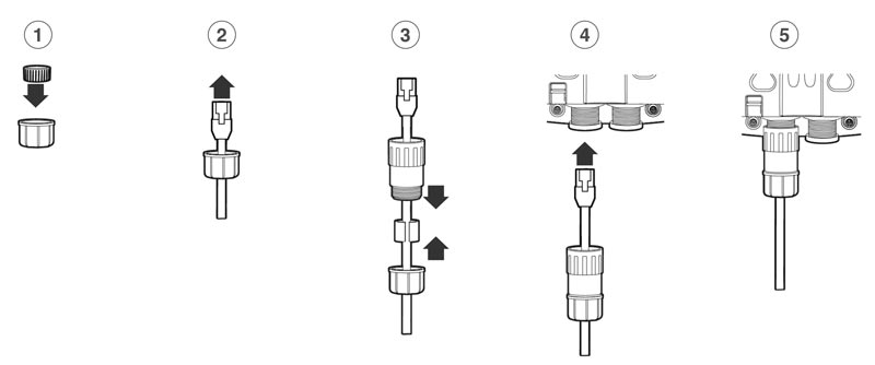
  • CAT 6/6A RJ45 Ethernet port termination plug

  • Anticorrosion sealant

  • Mounting straps

  • Cisco product documentation and pointer card

Unpacking the Access Point

To unpack the AP, follow these steps:

Procedure


Step 1

Unpack and remove the AP and the accessory kit from the shipping box.

Step 2

Return the packing material to the shipping container and save it for future use.

Step 3

Verify that you have received the following items:

  • The access point

  • Accessory kit (Ethernet port termination plug, ground lug kit)

  • MA-MNT-MR-16 Mounting bracket

  • CW-ACC-KIT1-00 accessory kit, only if you have ordered this optional accessory kit along with the AP.

If any item is missing or damaged, contact your Cisco representative or reseller for instructions.


Optional Tools and Hardware from Cisco

Depending on what you ordered, the following optional equipment may be part of your shipment:

Additional Tools and Hardware Required for Installation

You must independently procure the following tools and materials, which might be required during the various stages of installing the AP:

  • Ground lug crimping tool (Panduit CT-720 with CD-720-1 die)

  • #2 Phillips Screwdriver

  • 5–mm Hex driver or Allen wrench

  • Adjustable wrench or 28–mm box wrench

  • 6-AWG copper ground wire

  • 10–mm open-end or box wrench

  • 13–mm box-end wrench or socket set

  • 16–mm box-end wrench or socket set

  • CAT6/6A cable of 0.2 to 0.35 inch (5 to 9 mm) diameter

  • Ethernet RJ-45 connector and installation tool

  • Ground rod, as required by local regulations

Cisco Orderable Accessories

Order the following accessories separately from Cisco:

  • AP-mounting brackets to mount the CW9163E AP.

    Mounting Brackets

    Description

    AIR-MNT-VERT1

    Vertical mount to a wall or 2 to 5 inch (51 to 127 mm) diameter pole

    MA-MNT-MR-16

    Vertical mount to a wall or 2.5 to 3.9 inch (63.5 to 99.06 mm) diameter pole

  • Accessory kits

    Accessory Kit

    Description

    CW-ACC-KIT1-00

    This kit contains the following items:

    • Ground lug (Qty: 1)

    • Grounding screws (Qty: 2)

    • CAT 6/6A Ethernet port plug and gland assembly (Qty: 5)

    • GNSS antenna cap (Qty: 1)

    • RJ45 port dust cap (Qty: 2)

    • Reset port cap (Qty: 2)

    • Waterproof N-type antenna caps (Qty: 4)

    AIR-ACC245LA-N=

    Lightning Arrestor kit

  • Supported power injectors.

    Power Source

    Description

    AIR-PWRINJ6=

    30 W rated single-port PoE injector

    AIR-PWRINJ7=

    65 W rated single-port PoE injector (802.3bt), mGig Ethernet

    IW-PWRINJ-60RGDMG=

    37 W rated power injector

    MA-INJ-4

    30 W rated single-port PoE injector

    Note

     
    This power injector is in End of Life (EoL) stage.

    MA-INJ-6

    60 W rated PoE injector (802.3bt), mGig Ethernet

Preinstallation Checks and Installation Guidelines

Because the AP is a radio device, it is susceptible to common causes of interference that can reduce throughput and range. Follow these basic guidelines to ensure the best possible performance:

  • Thoroughly review the information provided in Installing the Access Point.

  • Install the AP in an area where structures, trees, or hills do not obstruct radio signals to and from the AP.

  • We recommend that you install the AP no higher than 40 feet to support the wireless clients on the ground. Mounting all the APs at the same height provides the best throughput.


Note


To calculate path loss and determine how far apart to install the APs, consult an RF planning expert.

Before you begin the installation process, ensure the following:

Typical Access Point Installation Components

The Cisco Catalyst Wireless 9163E Series Outdoor is designed to be installed in an outdoor environment, such as the exterior roof overhang of a tall building or a streetlight pole. Carefully review the Components in a Typical Access Point Installation to become familiar with the system components, connectors, indicators, cables, system interconnection, and grounding.

Figure 1. Components in a Typical Access Point Installation
1

Building roof overhang

6

Ground

2

Shielded outdoor-rated Ethernet (CAT6 or better) cable1

7

Power cord

3

Water drip loop

8

Power injector

4

6-AWG copper grounding wire 1

9

Shielded Ethernet (CAT6 or better) cable1

5

Ground rod1

10

Controller (through a switch)

1 Independently sourced by the user.

Preparing the AP for Installation

Before you mount and deploy the AP, we recommend that you perform a site survey (or use the site planning tool) to determine the best location to install your AP.

You should have the following information about your wireless network on hand:

  • AP locations

  • AP-mounting options: To a vertical wall or pole


Note


The AP can be mounted in various orientations. Depending on the orientation, you may have to purchase additional mounting hardware. For more information, see the Mounting the Access Point section.
  • AP power options: 802.3at (PoE+), 802.3af (PoE), and 802.3bt

  • Operating temperature:

    • Without solar derating: -40° to 149℉ (-40° to 65℃) and 131℉ (55℃)

    • With solar derating: -40° to 131℉ (-40° to 55℃) and 131℉ (55℃)

  • Console access using the console port

    We recommend that you use a console cable that is one meter or less in length.


    Note


    The AP may face issues while booting if you use an unterminated console cable (not plugged into any device or terminal) or a console cable that is more than one meter in length.

We recommend that you prepare a site map showing AP locations so that you can record the device MAC addresses from each location and return them to the person who is planning or managing your wireless network.

Performing a Preinstallation Configuration (Optional)

Performing the following procedures ensures that the AP installation and the initial operation proceed as expected. This procedure is optional.


Note


If your controller is configured properly, you can install the AP in its final location and connect it to the network from there. For additional information, see Deploying the Access Point in a Wireless Network.
The preinstallation configuration setup is illustrated in Preinstallation Configuration Setup:
Figure 2. Preinstallation Configuration Setup

To perform preinstallation configuration, follow these steps:

Procedure


Step 1

Ensure that the Cisco Controller Distribution System port is connected to the network. Use the procedure for the CLI or the GUI interface, as described in the release-appropriate Cisco Catalyst 9800 Series Wireless Controller Software Configuration Guide.

  1. Ensure that the AP has Layer 3 connectivity to the Cisco Controller Management and AP-Manager interfaces.

  2. Configure the switch to which the AP should be attached. See the release-specific Cisco Catalyst 9800 Series Wireless Controller Software Configuration Guide for the release your controller is running on.

  3. Set the controller as the primary controller so that the new AP always joins it.

  4. Ensure that you have enabled DHCP on the network.

    The AP must receive its IP address through DHCP.

    Note

     
    The DHCP server assigns an IP address to an 802.11AX Cisco AP only if a default router (gateway) is configured on the DHCP server (enabling the AP to receive its gateway IP address) and the gateway ARP is resolved.
  5. Ensure that the network is configured not to block the CAPWAP UDP ports.

  6. The AP must be able to find the IP address of the controller. This can be accomplished using DHCP, DNS, or IP subnet broadcast. This guide describes the DHCP method to convey the controller IP address. For other methods, refer to the product documentation. For more information, see Configuring DHCP Option 43.

    Note

     
    The AP requires a Gigabit Ethernet (GbE) link to prevent the Ethernet port from becoming a bottleneck for traffic because wireless traffic speeds exceed the transmit speeds of a 10/100 Ethernet port.

Step 2

Apply power to the AP.

  1. When the AP attempts to connect to the controller, the LED cycles through an off, green, and red sequence, taking up to five minutes.

    Note

     
    If the AP remains in this mode for more than five minutes, the AP is unable to find the primary controller. Check the connection between the AP and the primary controller and ensure they are on the same subnet.
  2. If the AP shuts down, check the power source.

  3. After the AP finds the primary controller, it attempts to download the software image if the AP software release differs from the controller release version. While this is happening, the status LED blinks blue.

  4. If the software image download is successful, the AP reboots.

Step 3

Configure the AP 802.11AX network settings using the controller CLI, controller GUI, or Cisco Catalyst Center.

Step 4

If the preinstallation configuration is successful, the status LED is green, indicating normal operation.

Disconnect the AP and mount it at the location you intend to deploy it on the wireless network.

Step 5

If the AP does not indicate normal operation, turn it off and repeat the preinstallation configuration.

Note


When you are installing a Layer 3 AP on a different subnet than the controller, ensure the following:

  • Ensure that a DHCP server is reachable from the subnet on which you want to install the AP.

  • The subnet has a route back to the controller, and ensure that the route back to the controller has the destination UDP ports 5246 and 5247 open for CAPWAP communications.

  • Ensure that the route back to the primary, secondary, and tertiary controllers allows IP packet fragments.

  • Ensure that the AP and the controller have a static 1-to-1 NAT to an outside address if address translation is used. (Port Address Translation is not supported.).


Mounting the Access Point

This section provides instructions to mount the AP. Personnel mounting the AP must have knowledge of the wireless AP, bridging techniques, and grounding methods.

Choosing a Mounting Kit

Access Point Mounting Kit

You can mount the AP vertically to a wall or a pole that best fits the installation application.

AP Mounting Kit2

Purpose

MA-MNT-MR-16

Fixed mounting kit for vertical mounting on a wall or for pole of diameter 2.5 to 3.9 inch (63.5 to 99.06 mm). See:

Wall Mounting the AP using the Meraki Kit

Pole Mounting the AP using the Meraki Kit

AIR-MNT-VERT1=

Fixed mounting kit for vertical mounting on a wall or for pole of diameter 2 to 3.9 inch (51 to 99.06 mm). See:

Wall Mounting the AP using the Cisco Kit

Pole Mounting the AP using the Cisco Kit

2 Mount the AP using no less than four screw holes on a bracket.

Note


  • When mounting an AP vertically, ensure that the AP is oriented with the LED indicators pointing down.

  • Mount the AP in such a way that all antenna ports and the console port are visible and accessible for future use.


Mounting Antenna

The procedure to install the supported antenna to the AP.

Antenna

Purpose

CW-ANT-O1-NS-00

Installing the Omnidirectional Antenna

CW-ANT-D1-NS-00

Wall Mounting the CW-ANT-D1-NS-00 Antenna

Pole Mounting the CW-ANT-D1-NS-00 Antenna

CW-ANT-GPS2-S-00

Mounting kit to install the GNSS antenna on a wall or pole of diameter 2.5 to 3.9 inch (63.5 to 99.06 mm). See:

Wall Mounting the GNSS Antenna

Pole Mounting the GNSS Antenna


Note


  • Align the AP’s omnidirectional antennas vertical to the ground.

  • Align the AP’s directional antenna such that the main beam is parallel to or tilted down toward the horizon.


Wall Mounting the AP using the Meraki Kit

The MA-MNT-MR-16 mounting kit contains a mounting bracket for wall mounting or pole mounting.

You can use the mounting bracket as a template to mark the mounting holes' positions for your installation, install the mounting bracket, and then attach the AP to the bracket.


Caution


The mounting wall, attaching screws, and wall anchors must support a 50-lb (22.7–kg) static weight.
Figure 3. Mounting Bracket for Wall and Pole Mounting

1

One of four keyhole lugs to mount the AP

4

Bracket mount holes for fastening the bracket to the wall

2

Mount plate security screw

5

One of four slots for steel band clamps, used for pole mounting (horizontal)

3

One of four slots for steel band clamps, used for pole mounting (vertical)

6

AP release tab

Figure 4. Mounting Bracket Dimensions

Before you begin

Ensure that you have the following materials before beginning to mount the AP to a wall:

Table 1. Material Required to Mount Access Point to a Wall using MA-MNT-MR-16 Kit

Materials Required

Supplied in the Kit?

Wall Mount Bracket

Yes

Ground lug and screws (provided with the access point)

Yes

Crimping tool for ground lug, Panduit CT-720 with CD-720-1 die

No

Four wall mounting screws

No

Four wall anchors (specified for all material)

No

Drill bit for wall anchors

No

Electric drill and standard screwdriver

No

#6 AWG ground wire

No

Shielded outdoor-rated Ethernet (CAT6 or better) cable

No

Grounding block

No

Grounding rod

No

10–mm box-end wrench or socket set

No

Procedure


Step 1

Use the mounting bracket as a template to mark four screw-hole locations on the mounting wall.

Step 2

Use four screws and, if required, wall anchors to attach the mounting plate to the mounting surface. These screws and anchors are to be sourced independently.

Note

 
  • You can use an exterior-grade plywood backboard to mount the AP to stucco, cement, or drywall.

  • The mounting wall, attaching screws, and wall anchors must support a 50-lb (22.7 kg) static weight.

Step 3

Slide and align the AP mounting holes against the mounting bracket such that the four keyhole lugs on the mounting bracket are inserted into the keyhole slots on the AP.

An audible click confirms that the AP is securely locked to the mounting bracket.

Note

 
The AP should be mounted with the status LED on the base facing downwards.

Step 4

Tighten the mounting plate security screw.

Step 5

Proceed with installing antennas, connecting the data cables, grounding the AP, powering, and configuring the AP.


Pole Mounting the AP using the Meraki Kit

The MA-MNT-MR-16 mounting kit contains a mounting bracket used for wall mounting and pole mounting. This kit can be used to install the AP on a pole or mast. It supports metal, wood, or fiberglass poles of 2.5 to 3.9 inch (63.5 to 99.06 mm) in diameter.

Figure 5. AP Mounted on a Pole

Before you begin

Ensure that you have the following materials before beginning to mount the AP to a pole:

Table 2. Materials Needed to Mount the AP on a Vertical Pole using MA-MNT-MR-16 Kit

Materials Required

Supplied in the Kit?

One wall mount bracket

Yes

Two stainless steel band clamps (adjustable to 2.5 to 3.9 inch (63.5 to 99.06 mm).

Yes

10–mm box-end wrench

No

A flathead screwdriver

No

Outdoor-rated shielded Ethernet cable

No

Ground lug (provided with the access point)

Yes

Ground block and rod

No

Crimping tool for ground lug, Panduit CT-720 with CD-720-1 die

No

#6 AWG ground wire

No

Procedure


Step 1

Select a mounting location on the pole to mount the AP.

You can attach the AP to a pole having a diameter of 2.5 to 3.9 inch (63.5 to 99.06 mm).

Step 2

Hold the bracket up against the pole and slide the two band straps through the top and bottom sets of mounting slots on the mounting bracket.

Step 3

Wrap the band straps around the pole and lock them.

Lightly tighten the clamps using a 10 mm wrench or Phillips head screwdriver. Only tighten them enough to keep the bracket from sliding down the pole.

Step 4

Align the AP mounting holes against the mounting bracket such that the keyhole slots on the back of the AP are inserted into the keyhole lugs on the mounting bracket.

Ensure that the AP is seated correctly on the keyhole lugs. An audible click confirms that the AP is securely locked to the mounting bracket.

Note

 
The AP should be mounted with the status LED on the base facing downwards.

Step 5

Place the AP in its final position.

Tighten the band clamps with the wrench or a screwdriver so that the AP does not slide on the pole. Ensure that the clamps are tight enough not to let the AP move.

Step 6

Tighten the mount plate security screw.

Step 7

Proceed with installing antennas, connecting the data cables, grounding the AP, powering, and configuring the AP.


Wall Mounting the AP using the Cisco Kit

The AIR-MNT-VERT1= mounting kit contains a mounting bracket for wall mounting or pole mounting.

You can use the mounting bracket as a template to mark the mounting holes' positions for your installation, install the mounting bracket, and then attach the AP to the bracket.


Caution


The mounting wall, attaching screws, and wall anchors must support a 50-lb (22.7–kg) static weight.
Figure 6. Mounting Bracket for Wall and Pole Mounting

1

One of four keyhole slots to mount the AP.

2

One of four slots for steel band clamps is used for pole mounting only.

3

Bracket mount holes are used to fasten the bracket to the wall. You can use bolts of up to 1/4” or 6 mm in diameter.

Figure 7. Mounting Bracket Dimensions

Before you begin

Ensure that you have the following materials before beginning to mount the AP to a wall:

Table 3. Material Required to Mount Access Point to a Wall using AIR-MNT-VERT1= Kit

Materials Required

Supplied in the Kit?

Ground lug and screws (provided with the access point)

Yes

Wall Mount Bracket

Optional, Cisco orderable accessory

Four M6 x 12–mm Hex-head Bolts

Yes

Crimping tool for ground lug, Panduit CT-720 with CD-720-1 die

No

Four wall mounting screws

No

Four wall anchors (specified for all material)

No

Drill bit for wall anchors

No

Electric drill and standard screwdriver

No

#6 AWG ground wire

No

Shielded outdoor-rated Ethernet (CAT6 or better) cable

No

Grounding block

No

Grounding rod

No

10–mm box-end wrench or socket set

No

Procedure


Step 1

Use the mounting bracket as a template to mark four screw-hole locations on the mounting wall. The mounting bracket screw hole locations are shown in Mounting Bracket for Wall and Pole Mounting. The dimensions of the mounting bracket are shown in Mounting Bracket Dimensions.

Step 2

Use four screws and, if required, wall anchors to attach the mounting plate to the mounting surface. These screws and anchors are to be sourced independently.

Note

 
  • You can use an exterior-grade plywood backboard to mount the AP to stucco, cement, or drywall.

  • The mounting wall, attaching screws, and wall anchors must support a 50-lb (22.7 kg) static weight.

Step 3

Screw an M6 x12–mm bolt into each of the four support bolt holes on the back of the AP. Do not screw the bolt all the way in, but leave a gap of approximately 0.13 inch (3.3 mm).

Step 4

Position the AP against the mounting bracket such that the four support bolts on the back of the AP slot are inserted into the keyhole slots on the mounting bracket.

Step 5

Slide the AP down to sit securely in the keyhole slots on the mounting bracket.

An audible click confirms that the AP is securely locked to the mounting bracket.

Note

 
The AP should be mounted with the status LED on the base facing downwards.

Step 6

Using a 10–mm wrench, tighten the four bolts that connect the AP to the bracket to 40 lbf-in (4.5 Nm) of torque.

Step 7

Proceed with installing antennas, connecting the data cables, grounding the AP, powering, and configuring the AP.


Pole Mounting the AP using the Cisco Kit

The AIR-MNT-VERT1= mounting kit contains a mounting bracket used for both wall mounting and pole mounting. This kit can be used to install the AP on a pole or mast. It supports metal, wood, or fiberglass poles of 2 to 3.9 inch (51 to 99.06 mm) in diameter.

Figure 8. AP Mounted on a Pole

1

One of four M6 keyhole slots for mounting the AP on the bracket.

2

Top and bottom sets of band clamp slots for passing the clamps through.

3

Top and bottom steel band clamps

4

Pole (wood, metal, or fiberglass), 2 to 3.9 inch (51 to 99.06 mm) diameter

Before you begin

Ensure that you have the following materials before beginning to mount the AP to a pole:

Table 4. Materials Needed to Mount the AP on a Vertical Pole using AIR-MNT-VERT1= Kit

Materials Required

Supplied in the Kit?

One wall mount bracket

Optional Cisco orderable accessory

Four M6 x12 mm hex head bolts

Yes

Two stainless steel band clamps (adjustable 2 to 3.9 inch (51 to 99.06 mm)

Yes

10–mm box-end wrench

No

Outdoor-rated shielded Ethernet cable

No

Ground lug (provided with the access point)

Yes

Ground block and rod

No

Crimping tool for ground lug, Panduit CT-720 with CD-720-1 die

No

#6 AWG ground wire

No

Procedure


Step 1

Select a mounting location on the pole to mount the AP. You can attach the AP to a pole having a diameter of 2.5 to 3.9 inch (63.5 to 99.06 mm).

Step 2

Hold the bracket up against the pole and slide the two band straps through the top and bottom sets of mounting slots on the mounting bracket.

Step 3

Wrap the band straps around the pole, lock them, and then lightly tighten the clamps using a 10 mm wrench or Phillips head screwdriver. Only tighten them enough to keep the bracket from sliding down the pole.

Step 4

Screw an M6 bolt into each of the four bolt holes on the backside of the AP. Do not screw the bolt in all the way. Leave a gap of about 0.13 inch (3.3 mm).

Step 5

Position the four bolts on the AP into the bracket keyhole slots.

Ensure that the AP is seated correctly in the slots. An audible click confirms that the AP is securely locked to the mounting bracket.

Note

 
The AP should be mounted with the status LED on the base facing downwards.

Step 6

Using a 10–mm wrench, tighten the four bolts that connect the AP to the bracket to 40 lbf-in (4.5 Nm) of torque.

Step 7

Place the AP in its final position. Tighten the band clamps with the wrench or the screwdriver so that the AP does not slide on the pole. Ensure that the clamps are tight enough not to let the AP move.

Step 8

Proceed with installing antennas, connecting the data cables, grounding the AP, powering, and configuring the AP.


Grounding the Access Point

The AP must be grounded before connecting power.

In all outdoor installations, you must follow these steps to ground the case properly:

Procedure


Step 1

If using insulated 6-AWG copper ground wire, strip the insulation required for the grounding lug.

Step 2

Use the appropriate crimping tool to crimp the bare 6-AWG copper ground wire to the supplied grounding lug.

Note

 
The grounding lug and hardware used must comply with local and national electrical codes.

Step 3

Open the anti-corrosion sealant (supplied) and apply a liberal amount over the metal surface called the Ground Pad, where the ground strap screw holes are located.

Step 4

Connect the grounding lug to the AP grounding screw holes using the supplied two Phillips head screws (M4 x10–mm) with lock washers. Tighten the grounding screw with 22 to 24 lb-in (2.5 to 2.7 Nm) of torque.

Step 5

If necessary, strip the other end of the ground wire and connect it to a reliable earth ground, such as a grounding rod or an appropriate grounding point on a metal streetlight pole that is grounded.

Figure 9. Position of the Ground Pad on the Right Side of the AP

1

Ground pad, where the ground strap screw holes are located.


Powering the Access Point

The AP supports Power-over-Ethernet (PoE) based power sources.

The AP is powered via the PoE input from an inline power injector. Depending on the configuration and regulatory domain, the required power for full operation is 802.3at.

Table 5. Cisco Catalyst Wireless 9163E AP Reduced Power Feature Matrix
SKU PoE-in/DC Input Radio 0 dBm Radio 1 dBm Radio 2 dBm Scan Radio Ethernet mGig BLE GNSS

SS

Per Path

SS

Per Path

SS

Per Path

2.4-GHz radio

5-GHz Primary radio

6-GHz Primary radio

CW9163E

.3af (15.4W)

1x1

17

1x1

17

disabled

disabled

1G

N

Y

.3at (30W)

2x2

22

2x2

22

2x2

AFC assigned

enabled

2.5G

Y

Y

Connecting a Power Injector

The AP supports the following power injectors:

Table 6. Supporting Power Injectors

Power Source

Description

AIR-PWRINJ6=

30 W rated single-port PoE injector

AIR-PWRINJ7=

65 W rated single-port PoE injector (802.3bt), mGig Ethernet

IW-PWRINJ-60RGDMG=

37 W rated power injector

MA-INJ-4

30 W rated single-port PoE injector

Note

 
This power injector is in End of Life (EoL) stage.

MA-INJ-6

60 W rated PoE injector (802.3bt), mGig Ethernet

The power injector provides with DC voltage to the AP over the Ethernet cable and supports a total end-to-end Ethernet cable length of 100 m (328 ft) from the switch to the AP.

When an optional power injector powers your AP, follow these steps to complete installation:

Procedure


Step 1

Before connecting the PoE to the AP, ensure that the AP is grounded (see Grounding the Access Point).

Step 2

Identify the components needed for the installation, see the Typical Access Point Installation Components.

Step 3

Connect a CAT6 or better Ethernet cable from your wired LAN network to the power injector.

Note

 
The installer is responsible for ensuring that powering the AP from this type of power injector is allowed by local and/or national safety and telecommunications equipment standards.

Step 4

Ensure that the antennas are connected and that the grounding cable is attached to the AP before you apply power to the AP.

Step 5

Connect a shielded outdoor-rated Ethernet (CAT6 or better) cable between the power injector and the AP's PoE-in connector.

Step 6

Connect the Ethernet cable to the AP PoE-In port.


Connecting an Ethernet Cable to the Access Point

Installing a CAT 6/6A Ethernet Cable and Gland Assembly to the Access Point

Figure 10. CAT 6/6a Cable Gland Assembly

1

CAT 6/6A RJ45 Plug

5

Screw nut

2

RJ45 wire load bar

Note the orientation into plug

6

Cable Seal (Cable OD range 5 mm to 7 mm)

3

Gasket

It is pre-attached to the Clamp ring.

7

Cable Seal (Cable OD range 7 mm to9 mm)

4

Clamp ring

8

Cable sealing nut

Before you begin

You must supply these tools and materials:

  • Shielded outdoor-rated Ethernet (CAT 6 or CAT 6A) cable with a diameter of 0.2 to 0.35 inch (5 to 9 mm)

  • CAT 6 RJ45 connector installation tool

  • Adjustable wrench or 18–mm box wrench


    Note


    We recommend the application of dielectric grease on the RJ45 connector pins as an additional layer of protection from moisture. The dielectric grease creates a moisture barrier preventing the RJ45 connector pins from corrosion if the gland's weathertight seal fails.


Procedure


Step 1

Disconnect the power to the power injector.

Step 2

Ensure a 6 AWG ground wire is connected to the AP (see Grounding the Access Point).

Step 3

Remove the covering cap from the PoE port.

Note

 
Verify that the cable gland has a rubber seal and gasket. Ensure that it is not damaged.

Caution

 
If the cable gland and rubber gasket are not installed correctly, it causes the cable grip to leak.

Step 4

Loosen and remove the cable sealing nut of the cable gland by turning it counterclockwise.

Figure 11. Visual Representation of CAT 6/6A Ethernet Cable Installation Procedure

Step 5

Insert the Ethernet cable's unterminated end through the cable sealing nut.

Pass the Ethernet cable through the appropriate size cable seal, then pull several inches of cable through the gland components.

Note


Install the proper cable seal that fits the OD of the Ethernet cable used.

Step 6

Insert the cable seal into the clamp ring, then install the cable seal nut back to the clamp ring.

Do not tighten the clamp ring.

Step 7

Install the CAT 6/6A RJ45 connector on the Ethernet cable's unterminated end using your Ethernet cable installation tool.

Follow the common CAT6/6A Ethernet connector installation procedures. Fold and crimp the connector metal strain lug end over the outer cable jacket, foil and ground wire if equipped.

Caution

 
Ensure the RJ45 connector end where the cable enters is free from cable foil, shielding, and jacket that was peeled back during termination. If any material is left this may cause internal component interference and fail to seal properly to the RJ45 port.

Step 8

Slide the terminated RJ45 connector into the clamp ring till it stops.

Pull the cable to ensure that the connector is seated into the clamp ring.

Step 9

Tighten the cable seal nut around the cable.

Using a 18mm or adjustable wrench, tighten the nut to 7-9 lbf-in (8 – 10 kgf-cm).

Step 10

Install the RJ45 cable gland assembly into the AP port.

Thread the screw nut onto the AP threaded port and tighten by hand to be sure the gland seals to the port. Torque to 15 lbf-in (17 kgf-cm), if possible.

Step 11

Route your Ethernet cable and cut off any excess cable.

Step 12

Install an RJ45 connector on the unterminated cable end and insert it into the power injector or device PoE port.

Note

 
Ensure the individual conductor sequence matches the opposite connection end. The typical sequence follows the T568B pinout standard.

Step 13

Turn on the power to the power injector.


Mounting Antennas

Installing the Omnidirectional Antenna

The CW-ANT-O1-NS-00 is an N-type connector omnidirectional Self-Identifying Antenna (SIA).

Procedure


Step 1

Match the antenna to the corresponding AP port based on the supporting radio band.

For more information, see Supported External Antennas.

Step 2

Connect the antennas to the N-connector on the AP.


Wall Mounting the GNSS Antenna

CW-ANT-GPS2-S-00 is a GNSS antenna with an integrated mounting bracket for mounting to a wall or a pole.

Figure 13. Wall Mounting a GNSS antenna

Before you begin

Ensure that you have the following materials before beginning to mount the GNSS antenna to a wall:

Table 7. Material Required to Mount CW-ANT-GPS2-S-00 to a Wall

Materials Required

Supplied in the Kit?

Wall/pole mount bracket

Yes

Two wall mounting screws

No

Two wall anchors (specified for all material)

No

Drill bit for wall anchors

No

Electric drill and standard screwdriver

No

Procedure


Step 1

Use the GNSS CW-ANT-GPS2-S-00 mounting bracket as a template to mark the two screw hole locations on the mounting wall.

Step 2

Use two screws and, if required, wall anchors to attach the mounting bracket to the mounting surface. These screws and anchors are to be sourced independently.

Note

 
You can use an exterior-grade plywood backboard to mount the GNSS antenna to stucco, cement, or drywall.

Step 3

Remove the protective cap and connect the antenna to the GNSS port.

The GNSS port is located at the top of the AP. See Connectors and Ports on the AP.


Pole Mounting the GNSS Antenna

The CW-ANT-GPS2-S-00 is a mounting bracket with the GNSS antenna for mounting the antenna to a wall or a pole.

Figure 14. Pole mounting a GNSS antenna

Before you begin

Ensure that you have the following materials before beginning to mount the GNSS antenna to a pole:

Table 8. Material Required to Mount CW-ANT-GPS2-S-00 to a Pole

Materials Required

Supplied in the Kit?

Wall/pole mount bracket

Yes

One stainless steel band clamp (adjustable 2.5 to 3.9 inch (63.5 to 99.06 mm)

Yes

A flathead screwdriver

No

Procedure


Step 1

Select a mounting location on the pole to mount the CW-ANT-GPS2-S-00 GNSS antenna bracket.

You can attach the antenna to a pole having a diameter of 2.5 to 3.9 inch (63.5 to 99.06 mm).

Step 2

Hold the bracket up against the pole and slide the band strap through the horizontal slot at the bottom of the mounting bracket.

Step 3

Place the GNSS antenna in its final position.

Tighten the band clamp with the wrench or a screwdriver so that the bracket does not slide on the pole. Ensure that the clamp is tight enough not to let the antenna move.

Step 4

Remove the protective cap and connect the antenna to the GNSS port.

The GNSS port is located at the top of the AP. See Connectors and Ports on the AP.


Wall Mounting the CW-ANT-D1-NS-00 Antenna

The CW-ANT-D1-NS-00 is a N-type connector directional antenna designed for wall-mounting applications.

Figure 15. Wall Mouting CW-ANT-D1-NS-00 Antenna to AP

1

Access point

2

CW-MNT-ART2-00 articulating mount

3

One of four screw anchors

4

One of four mounting screws

5

Nut

6

Washer

7

Joint bolt

8

Articulating arm

9

Joint bolt

10

Antenna plate

11

CW-ANT-D1-NS-00 antenna

12

N-type connector

Before you begin

Ensure that you have the following materials before beginning to mount the CW-ANT-D1-NS-00 antenna to a wall:

Table 9. Material Required to Mount CW-ANT-D1-NS-00 to a Wall

Materials Required

Supplied in the Kit?

CW-MNT-ART2-00 Articulating mount

Yes

Four M5 x 13 mm screws

Yes

Joint bolts and nuts

Yes

Wall mount screws

No

Drill bit for wall anchors

No

Electric drill and standard screwdriver

No

Procedure


Step 1

Attach the articulating arm segment to the large arm base plate using the provided joint bolt and nut before securing the entire arm assembly to the base plate.

Step 2

Position the antenna at the desired location on the mounting surface.

Step 3

Utilize the large arm base plateas a template to outline the positions for the mounting holes.

Step 4

Use a 0.1360-inch (3.4772 mm) drill bit to create pilot holes at the designated markings for the mounting holes.

Step 5

Identify the pilot holes, insert wall anchors into each one, and secure them firmly in place.

Step 6

Align the large arm base plate with the fastener holes and use screws with a diameter of up to 6 mm and a minimum length of 1-1/4 inches (to be procured separately) to affix the plate against the wall.

Step 7

Fasten the antenna to the small antenna plate and tighten it into place using the screws included in the package.

Step 8

Fasten the vertical tilt joint of the small antenna plate to the articulating arm using the bolt and nut provided in the kit.

Step 9

Connect the N-type connectors on the antenna to the antenna ports on the access point. The cables should be connected to the corresponding colors on the AP antenna ports.


Pole Mounting the CW-ANT-D1-NS-00 Antenna

The CW-ANT-D1-NS-00 is a N-type connector directional antenna designed for pole-mounting applications.

Figure 16. Pole Mounting CW-ANT-D1-NS-00 Antenna to AP

1

Articulating arm base plate

2

Nut

3

Washer

4

Joint bolt

5

Articulating arm

6

Joint bolt

7

Antenna plate

8

CW-ANT-D1-NS-00 antenna

9

N-type connector

10

Access point

Before you begin

Ensure that you have the following materials before beginning to mount the CW-ANT-D1-NS-00 antenna to a pole:

Table 10. Material Required to Mount CW-ANT-D1-NS-00 to a Pole

Materials Required

Supplied in the Kit?

CW-MNT-ART2-00 Articulating mount

Yes

Four M5 x13 mm screws

Yes

Joint bolts and nuts

Yes

Two stainless steel band clamps

Yes

Flathead screwdriver

No

Philips PH2 screwdriver

No

Procedure


Step 1

Attach the articulating arm segment to the large arm base plate using the provided joint bolt and nut before securing the entire arm assembly to the base plate.

Step 2

Position and mount the pole mounting flange onto the pole or mast using the hose clamps provided in the kit.

The hose clamps should pass through the slots on the free mounting flange bracket.

Step 3

Tighten the hose clamps and set screws until the flange is fully secure on the mast.

Adjust the flange to its final position. Then, use a slotted screwdriver to tighten the screws on the hose clamps.

Step 4

Fasten the antenna to the small antenna plate and tighten it into place using the screws included in the package.

Step 5

Fasten the vertical tilt joint of the small antenna plate to the articulating arm using the bolt and nut provided in the kit.

Step 6

Connect the N-type connectors on the antenna to the antenna ports on the access point. The cables should be connected to the corresponding colors on the AP antenna ports.