- Overview
- Building Up a Fully Meshed Network Between Cisco UMGs
- Managing Endpoints with One-to-One Cisco UMG Redundancy
Setting Up a Messaging Network Controlled by Cisco UMG Using a Distributed Model
This chapter describes how to set up a complete Cisco UMG controlled messaging network using a distributed model. The following topics are discussed:
• Building Up a Fully Meshed Network Between Cisco UMGs
•Managing Endpoints with One-to-One Cisco UMG Redundancy
•Managing the Avaya Interchange Endpoint on Cisco UMG with Manual Provisioning
•Monitoring and Manually Synchronizing Cisco UMG Directory Exchange
•Message Routing and Delivery on Cisco UMG
•Setting Up Directory Lookup with TUI or VVE Interface
•Setting Up Spoken-Name Confirmation Across AutoRegistered Cisco Unity Express Endpoints
•Using System Distribution Lists Across Cisco Unity Express Systems
•Setting Up NAT Tables on Cisco UMG
•Setting Up Backup and Restore for Cisco UMG
Overview
In this messaging network, Cisco Unity Express, Cisco Unity, and Avaya Interchange are all present as endpoints, the Cisco UMGs are setup with full active-standby redundancy. Figure 1 shows a network diagram and Table 1, Table 2, Table 3, and Table 4 contain detailed information about the topology.
Figure 1 Cisco UMG Network Setup Case Study Topology

Table 1 Headquarters Information

Note For the west region, assume all the Cisco Unity Express nodes were upgraded to 3.1.
Table 2 West Region Information
Note For the east region, assume none of Cisco Unity Express nodes was upgraded to version 3.1.
Table 3 East Region Information
Table 4 North Region Information
|
|
|
|
|
|
|
|---|---|---|---|---|---|
Umg-P |
600 |
10.60.60.200 |
N/A |
||
Interchange |
610 |
10.60.60.11 |
interchange |
203 |
Interchange.headquarters.com |
NTP |
n/a |
10.60.80.254 |
HQntp |
n/a |
n/a |
Note This document does not cover how to set up the domain and NTP. For information on this topic, see the Cisco UMG System Administrator Guide. Ensure the system time is synchronized in the Cisco network.
Building Up a Fully Meshed Network Between Cisco UMGs
The following example is for the west region Cisco UMG-P. The configuration for the other Cisco UMGs is similar.
umg-w-1(config)# network local messaging-gateway 400
Note Configure the network local ID on all the Cisco UMGs.
umg-w-1(config)# network messaging-gateway 401 10.60.70.201
umg-w-1(config)# network messaging-gateway 500 10.60.80.200
umg-w-1(config)# network messaging-gateway 501 10.60.80.201
umg-w-1(config)# network messaging-gateway 300 10.60.30.200
umg-w-1(config)# network messaging-gateway 301 10.60.30.201
umg-w-1(config)# network messaging-gateway 600 10.60.60.200
umg-w-1(config)#exit
To verify the full meshed network:
umg-w-1# show messaging-gateway
LocationID Hostname NAT
------------------------------------------------------------
401 10.60.70.201 disabled
500 10.60.80.200 disabled
501 10.60.80.201 disabled
300 10.60.30.200 disabled
301 10.60.30.201 disabled
600 10.60.60.200 disabled
Local Gateway ID: 400
Managing Endpoints with One-to-One Cisco UMG Redundancy
Managing Cisco Unity 3.1 and Later Versions
Endpoint autoregistration involves configuration on both Cisco Unity Express and Cisco UMG. This example of the west region in this case, uses cue-w-1 as an example. The configurations for cue-w-2 and cue-w-3 are similar.
Registration Configuration on Cisco Unity Express
•Cisco Unity Express prerequisite configuration of the network Location ID
Cue-w-1(config)# network location id 410
Cue-w-1(config-location)# abbreviation cueW1
Cue-w-1(config-location)# email domain 10.60.70.11
cue(config-location)# voicemail phone-prefix 408
cue(config-location)# enable
cue(config-location)# exit
cue(config)# network local location id 410
Primary gateway IP address, registration listening port number, and username/password
Cue-w-1(config)# messaging-gateway primary 400 10.60.70.200
Cue-w-1(config-messaging-gateway)# username cue_410 password text pswd
Cue-w-1(config-messaging-gateway)# exit
•Secondary gateway IP address and registration listening port number
Cue-w-1(config)# messaging-gateway second 401 10.60.70.201
Cue-w-1(config-messaging-gateway)# username cue_410 password text pw1
Cue-w-1(config-messaging-gateway)# exit
•Registration command that starts the process
cue(config)# messaging-gateway register
Corresponding Configurations on Cisco UMG
•Registration authentication username and password
Umg-w-1(config-reg)# username cue_410 password text pw1
Umg-w-1(config-reg)# username cue_410 password text pw1
Umg-w-1(config-reg)# exit
Note For other Cisco Unity Express endpoints in the west region, configure similar credentials.
For the secondary Cisco UMG in the west region, use to the same configuration.
•Block any Cisco Unity Express endpoint on the restricted list if any (optional). In this case, the Cisco UMG in the west region rejects all the Cisco Unity Express endpoints in the east region.
Umg-w-1(config-reg)> block location-id 310
Umg-w-1(config-reg)> block location-id 311
Umg-w-1(config-reg)> block location-id 312
Verifying Registration Status
umg-w-1# show registration users|status
umg-w-1# show endpoint local
cue-w-1# show messaging-gateway
Managing Cisco Unity Express Versions Earlier Than 3.1
This scenario requires manual provisioning on Cisco UMG.
(The east region in this case, covers all three Cisco Unity Express configurations on UMG-e-1)
•Cisco Unity Express prerequisite configuration
This example is for cue-e-1. The configurations for cue-e-2 and cue-e-3 are similar.
Cue-e-1(config)# network location id 310
Cue-e-1(config-location)# abbreviation cueE1
Cue-e-1(config-location)# email domain 10.60.30.11
Cue-e-1(config-location)# voicemail phone-prefix 716
Cue-e-1(config-location)# enable
Cue-e-1(config-location)# exit
Cue-e-1(config)# network local location id 310
Cue-e-1(config)# network location id 300
Cue-e-1(config)# email domain 10.60.30.200
Cue-e-1(config)# exit
•Configuration for cue-e-3 on umg-e-1
Umg-e-1(config)> endpoint 312 cue
Umg-e-1(config-endpoint)> broadcast-id 312
Umg-e-1(config-endpoint)> domain cue-e-1.cueE.headquarters.com
Umg-e-1(config-endpoint)> hostname 10.60.30.31
Umg-e-1(config-endpoint)> messaging-gateway secondary 301
Umg-e-1(config-endpoint)> prefix 917
Umg-e-1(config-endpoint)> enable
Note The domain on the above can be the IP address of Cisco Unity Express, in this case, 10.60.30.31.
•Configuration for cue-e-1 and cue-e-2 on umg-e-1
Both cue-e-1 and cue-e-2 have the same prefix 716.
Umg-e-1(config)> endpoint 310 cue
Umg-e-1(config-endpoint)> broadcast-id 311
Umg-e-1(config-endpoint)> domain 10.60.30.11
Umg-e-1(config-endpoint)> hostname 10.60.30.11
Umg-e-1(config-endpoint)> messaging-gateway secondary 301
Umg-e-1(config-endpoint)> prefix 716 number-only
Umg-e-1(config-endpoint-extension)> extension 8561001
Umg-e-1(config-endpoint-extension)> extension 3241002
Umg-e-1(config-endpoint)> enable
Umg-e-1(config)> endpoint 311 cue
Umg-e-1(config-endpoint)> broadcast-id 311
Umg-e-1(config-endpoint)> domain 10.60.30.21
Umg-e-1(config-endpoint)> hostname 10.60.30.21
Umg-e-1(config-endpoint)> messaging-gateway secondary 301
Umg-e-1(config-endpoint)> prefix 716 number-only
Umg-e-1(config-endpoint-extension)> extension 1241001
Umg-e-1(config-endpoint-extension)> extension 5321002
Umg-e-1(config-endpoint)> enable
Note For older versions of Cisco Unity Express, you must enter prefix-number-only mode with extension information only if multiple endpoints are sharing the same prefix.
•Check the registration information on umg-e-1:
umg-e-1> show endpoint local
A total of 3 local endpoint(s) have been found:
Location Location Endpoint Endpoint Primary Secondary
ID Prefix Type Status Gateway Gateway
------------------------------------------------------------------------------------------
310 716 CUE Enabled 300 301
311 716 CUE Enabled 300 301
312 917 CUE Enabled 300 301
umg-e-1> show mailbox 311
2 mailbox(s) has been found for location 311
7161241001
7165321002
umg-e-1> show mailbox 310
2 mailbox(s) has been found for location 310
7165550111
7165550112
umg-e-1> show mailbox 312
No mailbox has been found for location 312
Note Only those manual endpoints with prefix-number-only extension configured have subscriber information on Cisco UMG's directory database.
Managing Cisco Unity and Manually Provisioning Cisco UMG
Note Manually provision Cisco UMG only if needed.
In this example of the headquarters configuration, Cisco Unity has multiple prefixes. This example includes the configuration for both Cisco UMG and Cisco Unity.
Configuration for HQunity on umgrtp
Configure on umgrtp-1:
Umgrtp-1(config)> endpoint 510 unity
Umgrtp-1(config-endpoint)> domain headquarters.com
Umgrtp-1(config-endpoint)> hostname HQunity.headquarters.com
Umgrtp-1(config-endpoint)> messaging-gateway secondary 501
Umgrtp-1(config-endpoint)> prefix 919
Umgrtp-1(config-endpoint)> enable
Umgrtp-1(config)> endpoint 511 unity
Umgrtp-1(config-endpoint)> domain headquarters.com
Umgrtp-1(config-endpoint)> hostname HQunity.headquarters.com
Umgrtp-1(config-endpoint)> messaging-gateway secondary 501
Umgrtp-1(config-endpoint)> prefix 714
Umgrtp-1(config-endpoint)> enable
Note Every prefix on Cisco Unity is counted as an individual endpoint on Cisco UMG, which means you must assign different Location ID.
Configuration for Cisco Unity
Defining the Cisco UMG Host Information on Cisco Unity DNS Server
Figure 2 Configuring the Cisco UMG Host (umgrtp) with a Primary IP Address (10.60.80.200)
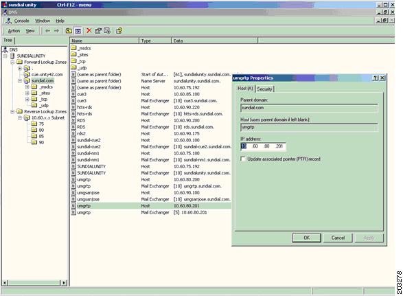
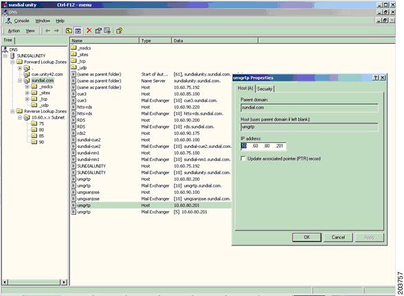
Figure 3 Configuring the Cisco UMG Host (umgrtp) with a Secondary IP Address (10.60.80.201)
Creating a Mail Exchange Record on Cisco Unity for Cisco UMG 1-1 Redundancy
Figure 4 Create MX Record for Primary Cisco UMG with Priority 10
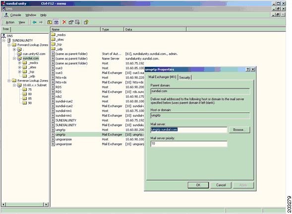
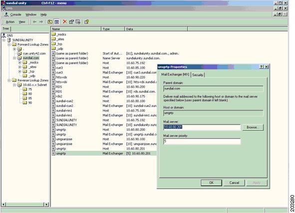
Figure 5 Create MX Record for Secondary Cisco UMG with Priority 5
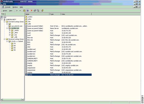
Note Cisco UMG redundancy is transparent for Cisco Unity. Cisco Unity relies on the DNS server to map the primary or secondary Cisco UMG host to the IP address depending on the Cisco UMG status and priority setup. (See Figure 6)
Figure 6 MX-records from Cisco Unity with Primary and Secondary Cisco UMG Information
Setting Up Cisco UMG on Cisco Unity as a Delivery Location with a Dial-ID
Figure 7 Add the Delivery Location on Cisco Unity to umgrtp
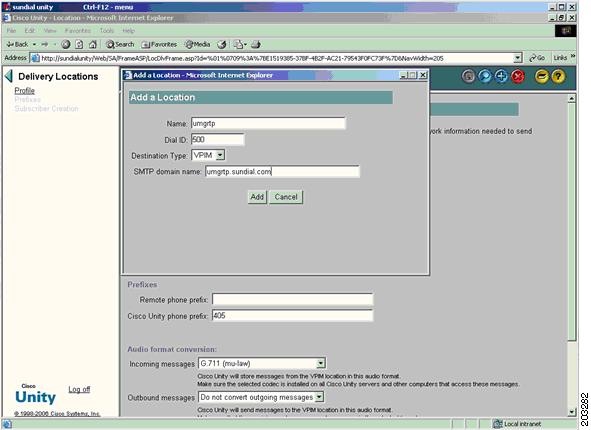
Figure 8 Delivery Location Setup with Other Parameters
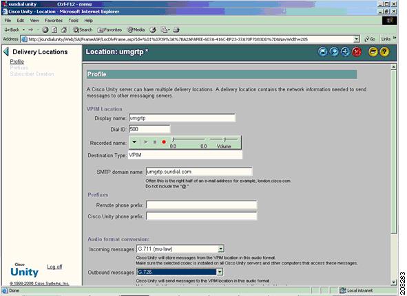
Note When adding the Cisco UMG host as the Delivery location, the Dial ID field on Cisco Unity is the Location ID of the Primary Cisco UMG to which Cisco Unity registered. Leave the Remote Phone Prefix field empty to indicate that any subscriber on Cisco Unity can dial any number outside by dialing the dial_ID followed with the real remote number. Depending on the Cisco Unity dial plan, you can leave the Cisco Unity Phone Prefix field empty or enter the prefix of the Cisco Unity endpoint on Cisco UMG.
Optionally Deploying VPIM Network Using Remote VPIM Subscribers Instead of Delivery Location
In this model, the customer has imported all the remote subscriber information into the Cisco Unity database. When Cisco UMG is inserted into the VPIM network with all remote subscribers registered, the customer can either move from a Remote VPIM subscriber setup to a delivery location setup or stay with a Remote VPIM subscriber setup by setting the VPIM location to the primary Cisco UMG Location ID.
Figure 9 Remote Subscriber VPIM Location Setup on Cisco Unity
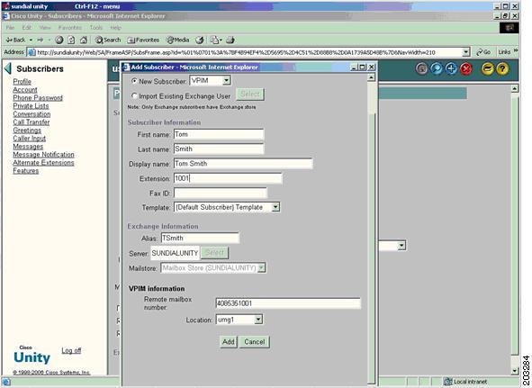
Note The deployment involves the information change on every remote VPIM subscriber's setup.
Verifying the Cisco Unity Endpoints on Cisco UMG
umgrtp-1> show endpoint local
A total of 2 local endpoint(s) have been found:
Location Location Endpoint Endpoint Primary Secondary
ID Prefix Type Status Gateway Gateway
------------------------------------------------------------------------------------------
510 919 Unity Enabled 500 501
511 704 Unity Enabled 500 501
Managing the Avaya Interchange Endpoint on Cisco UMG with Manual Provisioning
The following example is for the north region.
Configuration on umg-n-1
In this example, there is only one Cisco UMG connected to Avaya Interchange, no failover is supported with Avaya Interchange because of the limitation on Avaya Interchange VPIM support.
Umg-n-1(config)> endpoint 610 unity
Umg-n-1(config-endpoint)> domain avaya.headquarters.com
Umg-n-1(config-endpoint)> hostname interchange.headquarters.com
Umg-n-1(config-endpoint)> prefix 203
Umg-n-1(config-endpoint)> enable
Configuration on Avaya Interchange
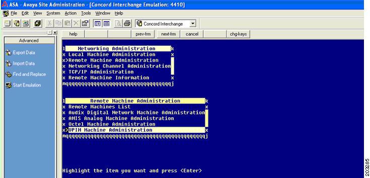
Step 1 From the Avaya Interchange Main Menu, choose Network Administration > Remote Machine Administration > VPIM Machine Administration.
Figure 10 VPIM Machine Admininstration Mode
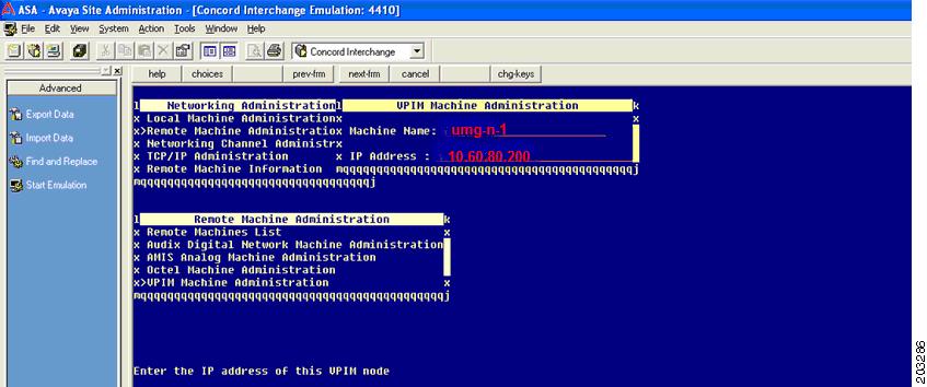
Step 2 On the VPIM machine administration screen, insert the Cisco UMG host name and IP address
In this example, the Machine Name could be umg-n-1 and the IP address should be 10.60.60.200.
Figure 11 Cisco UMG Configuration on Remote-Machine Configuration Window
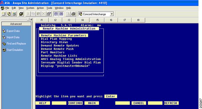
Step 3 From the Avaya Interchange Main menu, choose Interchange Administration > Remote Machine Administration > Remote Machine Parameters.
Figure 12 Remote Machine Parameter Configuration Mode
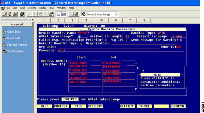
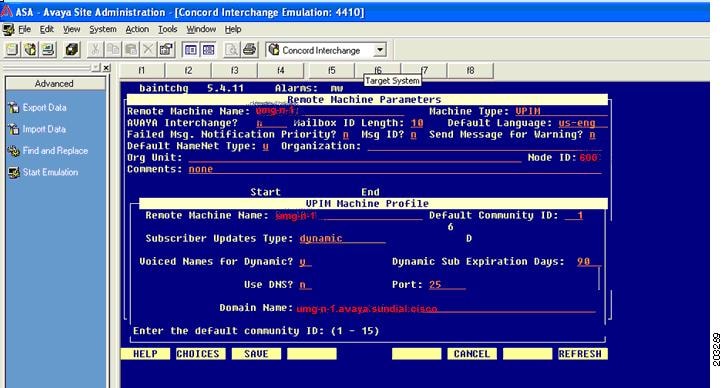
Step 4 On the Remote Machine Parameters screen configure the following:
–Cisco UMG name
–Location ID
–E164 numbers.
Figure 13 Basic Remote Machine Parameters Configuration
Step 5 Continue on the Remote Machine Parameters screen.
Figure 14 Detailed Remote Machine Parameters Configuration
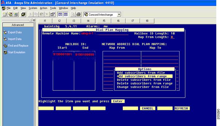
Step 6 If you must map the dial plan with network dial plan, exit from the Remote Machine Parameters screen and choose Interchange Administration > Remote Machine Administration > Dial-Plan Mapping.
Figure 15 Dial-Plan Mapping Configuration
Note The configuration of other Customer Service parameters, such as Queue and CDR, is not within the scope of this document.
Verifying from umg-n-1
Umg-n-1> show endpoint local
A total of 1 local endpoint(s) have been found:
Location Location Endpoint Endpoint Primary Secondary
ID Prefix Type Status Gateway Gateway
-----------------------------------------------------------------------------------------
510 919 Interchange Enabled 600 N/A
Monitoring and Manually Synchronizing Cisco UMG Directory Exchange
The Cisco UMG is an intelligent agent that handles directory information exchange automatically without any manual provisioning effort. The directory exchange can happen between:
•Multiple Cisco UMGs
•Cisco UMG and Cisco Unity Express systems
However, the directory exchange is limited with the autoregistered endpoints, so the directory exchange on Cisco Unity, Cisco Unity Express earlier than version 3.0, and Avaya Interchange is not supported. If you want subscriber level information on the Cisco UMG for those manual endpoints, you can configure the Cisco UMG to use prefix-number-only mode.
During a directory exchange, the following events will occur:
•When the Cisco UMG is first time inserted into a Cisco UMG-controlled messaging network, a full directory exchange is triggered between Cisco UMGs.
•When a Cisco Unity Express first time registers with its primary Cisco UMG, a full directory exchange is triggered between the Cisco Unity Express and its primary Cisco UMG. The secondary Cisco UMG gets information updates from the primary Cisco UMG.
•When any subscriber information is changed on Cisco Unity Express, a directory update occurs between Cisco Unity Express and its primary Cisco UMG. Next a directory exchange occurs between the primary Cisco UMG and all its peer gateways through the fully meshed unicast network.
•When Cisco Unity Express or Cisco UMG goes down and comes back online, a directory exchange is triggered on Cisco Unity Express and Cisco UMG, and across all the Cisco UMGs in the network.
•When a Cisco UMG detects out-of-sync data either from its endpoints or its peer Cisco UMGs, it tries to perform a directory update to recover. If it cannot recover, a full directory exchange is triggered.
Although the Cisco UMG can synchronize the directory information across your entire network, a set of CLI commands for Cisco Unity Express 3.1 and Cisco UMG 1.0 enable you to manually perform a directory exchange if the automatic resynchronization takes too long or is not invoked.
To manually perform a directory exchange, configure both Cisco Unity Express and the Cisco UMG as described below.
Manually Synchronizing Cisco UMG Directory Exchange on Cisco Unity Express
To synchronize directory exchange for Cisco Unity Express, use the following command:
messaging-gateway directory exchange [full | update]
Manually Synchronizing Cisco UMG Directory Exchange on Cisco UMG
To synchronize directory exchange on Cisco UMG, use the following commands:
directory exchange endpoint request [full | update]
directory exchange endpoint request [full | update] LOCATIONID
directory exchange messaging-gateway request [full | update]
directory exchange messaging-gateway request [full | update] LOCATIONID
directory exchange messaging-gateway send [full | update]
directory exchange messaging-gateway send [full | update] LOCATIONID
Note Use the manual directory-exchange only when out-of-sync directory information cannot be fixed by the automatic directory-exchange processes.
When applying the CLI commands shown above, examine the available bandwidth before flooding all the directory exchange information to endpoints or Cisco UMGs. If possible, use the commands only for certain nodes, during off-peak hours.
Verifying the Directory Information Exchange on the Cisco UMGs in the Network
Verifying the Endpoint
This example is for the Cisco UMG on East Region, umg-e-1.
umg-e-1> show endpoint local
A total of 3 local endpoint(s) have been found:
Location Location Endpoint Endpoint Primary Secondary
ID Prefix Type Status Gateway Gateway
------------------------------------------------------------------------------------------
310 716 CUE Enabled 300 301
311 716 CUE Enabled 300 301
312 917 CUE Enabled 300 301
umg-e-1> show endpoint network
A total of 6 network endpoint(s) have been found:
Location Location Endpoint Primary Secondary
ID Prefix Type Gateway Gateway
------------------------------------------------------------------------------------------
510 919 Unity 500 501
511 704 Unity 500 501
410 408 CUE 400 401
411 408 CUE 400 401
412 650 CUE 400 401
610 203 Interchange 600 n/a
Verifying the Subscriber
This example is for umg-e-1 and umg-w-1.
Umg-e-1# show mailbox 410
2 mailbox(s) has been found for location 410
4085550101
4085550102
The two subscriber numbers are exchanged from automatic directory exchange.
Umg-w-1# show mailbox 310
2 mailbox(s) has been found for location 310
7165550101
7165550102
The 2 subscriber numbers are exchanged by manual provisioning.
Umg-w-1# show mailbox 510
No mailbox has been found for location 510
No automatic directory exchange and manual provisioning.
Note All the Cisco UMGs in the network must have identical directory tables.
For autoregistered endpoints, the directory table contains the subscriber level information.
For manually provisioned endpoints, the directory table contains the subscriber level information only if prefix-number-only mode is enabled and the extensions are manually configured.
For manually provisioned endpoints without prefix-number-only sub mode enabled, no subscriber level information is in the directory table.
Message Routing and Delivery on Cisco UMG
The Cisco UMG (primary or secondary) that hosts an endpoint is responsible for routing the messages from that endpoint. The Cisco UMG utilize information from the directory table to route messages. Messages are routed differently, depending on the registration method of the destination endpoint.
If the destination endpoint is an autoregistered endpoint, the Cisco UMG routes on the subscriber level, which means the Cisco UMG searches for the destination number in its directory table to find the termination node.
If the destination endpoint is a manually provisioned endpoint, the Cisco UMG first routes using the prefix. If only one location with the prefix is found in the directory table, the routing is complete. If more than one location is found with the prefix, the Cisco UMG next looks at the prefix + extension level, which is configured under prefix-number-only mode.
For any VPIM message received on the Cisco UMG, the message destination "To" field could be a System Distribution List (SDL), SBM, or a subscriber number (E.164 phone number scheme). SDLs are matched first. If an SDL overlaps any other number, the SDL masks that number. All SDLs must begin with a numerical sequence that is unique to the system.
The Cisco UMG resolves the destination in the precedence of SDL, SBM, and subscribers. If the message destination does not match any of the existing SDLs, the Cisco UMG searches for a match in the list of configured broadcast endpoints. If no match is found, the Cisco UMG tries to resolve the message destination as a subscriber. If a match is still not found, the message is dropped, resulting in a Non-Delivery-Receipt (NDR).
You can configure a default route on Cisco UMG in case no destination is matched in Cisco UMG's database. For example, in the west region, the default route can be set up to point to cue-w-1, as shown below:
Umg-w-1(config)# network default-route 410
Umg-w-1> show network default-route
Note In Cisco UMG 1.0, The default route can be a local endpoint or a peer Cisco UMG. However, to avoid looping, there must be a default route plan, such that no message ever gets passed to more than two Cisco UMGs. In other words, if at any time an originating Cisco UMG specifies another Cisco UMG as a default route, that Cisco UMG must be the terminating Cisco UMG and therefore should have its default route set to a local endpoint.
When the address and route are resolved, the message is inserted into delivery queue and is ready to deliver. You can configure DDR and NDR timers to handle any delivery retry and failure cases.
Table 5 lists the DDR reason codes from Cisco UMG 1.0:
Table 5 Cisco UMG NDR reason codes
To check the Cisco UMG messaging routing and delivery statistics, use the show statistics command on the Cisco UMG, as shown below:
Umg-w-1> show statistics
SMTP Receive Failure: 0
SMTP Sent Failure: 0
SMTP Rejected: 2
NDR Message Generated: 0
DDR Message Generated: 0
Number of Lookup Request: 0
SDL Message Received: 0
SDL Message Sent: 0
SBM Message Received: 0
DirEx Message Received: 14
DirEx Message Send: 12
VPIM Message Received: 0
VPIM Message Sent: 0
Total SMTP Message Received: 14
Total SMTP Message Sent: 12
Setting Up Directory Lookup with TUI or VVE Interface
In Cisco UMG 1.0, a global search option is available to the end users when no match is found in the endpoint's local database (Cisco Unity Express).
You must enable the feature on the endpoint during the registration process. After configuring the hosting message gateway username and password, use the following command before starting the registration process.
cue(config)# messaging-gateway directory lookup tui-prompt
To check the feature's availability on the endpoint:
cue# show messaging-gateway
Messaging gateways:
AutoRegister to gateway(s) : Enabled
Remote directory lookup : Enabled (with TUI prompt)
Note To use the Cisco VVE interface, VoiceView Service must be enabled on Cisco Unity Express and a URL must be defined on the Cisco Unified CME telephony-interface. For detailed configuration information, see the Cisco Unified CME System Administrator's Guide and the Cisco Unity Express Administrator's Guide.
Directory lookup can be enabled with or without TUI confirmation.
Setting Up Spoken-Name Confirmation Across AutoRegistered Cisco Unity Express Endpoints
By default, spoken name is disabled on the Cisco UMG, which means that the spoken names received from Cisco Unity Express endpoints are not stored in the Cisco UMG directory database, and the spoken name are not part of the directory exchange with its peers. When this feature is enabled, Cisco Unity Express caches the location spoken names and plays them back to the end user.
To invoke this feature, you must configure both Cisco Unity Express and Cisco UMG:
On Cisco Unity Express:
Cue-w-1(config)# remote cache enable
Note Remote cache is mandatory for the Cisco UMG spoken-name feature.
On Cisco UMG
umg-w-1(config)# spoken-name enable
umg-w-1# show spoken-name
Spoken name is enabled.
If Cisco Unity Express already registered with the Cisco UMG before spoken-name is enabled, you must use the following CLI to trigger directory exchange to update spoken-name information:
Cue-w-1(config)# no messaging-gateway registration
Cue-w-1(config)# messaging-gateway registration
If spoken-name is already stored in the Cisco UMG database, disabling spoken-name does not delete the entry from the directory table until the new directory updates occurs.
Using System Distribution Lists Across Cisco Unity Express Systems
System Distribution Lists (SDLs) are created and managed in EXEC mode, not configuration mode. Each SDL can have one or more members, each of which could be one of the following entities:
•A subscriber
•Another SDL list
SDLs are shared among Cisco UMGs and can be managed on any Cisco UMG in a network.
SDLs are created and edited in list-management mode, which is the submode of EXEC mode. When list-management mode is exited on one Cisco UMG, all SDL changes are pushed out to all other Cisco UMGs in the network. At any time, only one Cisco UMG can manage the SDL information. Other Cisco UMGs are not able to enter list-management mode to manage SDLs until the Cisco UMG that was in the list-management mode exits from that mode or a 5-minute timeout when there is no exit request from the Cisco UMG that is currently in list-management mode.
As an example, the following sections show how to create three SDLs. These SDLs are for:
•West region
•East region
•Both west region and the east region
In this example, umg-w-1 is the master Cisco UMG.
Creating an SDL with Privileges
umg-w-1# list-manager
Locking system distribution lists...[OK] --> The umg-w-1 declare itself as the master UMG
## The following is the SDL list of the west region ##
Umg-w-1(listmgr)# list number 900 --> The list number must be a unique number
Umg-w-1(listmgr-edit)# name SDL_WEST
umg-w-1(listmgr-edit)# member 4085550101 type sub
umg-w-1(listmgr-edit)# member 4085550102 type sub
umg-w-1(listmgr-edit)# member 4085550001 type sub
umg-w-1(listmgr-edit)# member 4085550003 type sub
umg-w-1(listmgr-edit)# privilege 4085550101 --> Assign the authority to 2 members
umg-w-1(listmgr-edit)# privilege 4085550001
## The following is the SDL list of the east region ##
Umg-w-1(listmgr)# list number 910 --> The list number must be a unique number
Umg-w-1(listmgr-edit)# name SDL_EAST
umg-w-1(listmgr-edit)# member 7165550021 type sub
umg-w-1(listmgr-edit)# member 7165550042 type sub
umg-w-1(listmgr-edit)# member 7165550061 type sub
umg-w-1(listmgr-edit)# member 7165550082 type sub
umg-w-1(listmgr-edit)# privilege 7165550021 --> Assign the authority to 2 members
umg-w-1(listmgr-edit)# privilege 7165550082
## the following is the SDL list of west and east regions
Umg-w-1(listmgr)# list number 999 --> The list number must be a unique number
Umg-w-1(listmgr-edit)# name SDL_E_W
umg-w-1(listmgr-edit)# member 900 type list
umg-w-1(listmgr-edit)# member 910 type list
umg-w-1(listmgr-edit)# privilege 7165550021 --> Assign the authority to 2 members
umg-w-1(listmgr-edit)# privilege 4085550101
Publishing the SDLs to All Peer Cisco UMGs in the Network
Use either the manual list publish command or exit from SDL configuration mode.
umg-w-1(listmgr)# list publish     --> This is optional CLI, SDL will get automatically
published when exiting from listmgr mode
LocationID Status Description
-----------------------------------------------------------
500 Published
501 Published
401 Published
300 Published
301 Published
600 Published
601 Published
# of network gateways published: 7
# of network gateways failed to publish:0
Unlocking the SDL Configuration
umg-w-1(listmgr-edit)# exit
umg-w-1(list)# exit
auto publishing to all ...
LocationID Status Description
500 Published
501 Published
401 Published
300 Published
301 Published
600 Published
601 Published
# of network gateways published: 7
# of network gateways failed to publish:0
Verifying the SDL Configuration on Any Cisco UMG in the System
umg-e-1(listmgr)# show list 900
Extension: 000
Name: SDL_WEST
Member(s): 4085550101 (subscriber)
4085550102 (subscriber)
4085550001 (subscriber)
4085550003 (subscriber)
-----
# of members: 4
umg-e-1# show list 900 privilege --> Under UMG exec mode
2 authorized sender(s) has been found for system distribution list 900:
4085550101
4085550001
Verifying that SDL is Synchronized Between Cisco UMGs
Use these commands to check the SDL versions on Cisco UMGs and verify that SDL is synchronized:
Umg-e-1 > show list tracking version
The version of system distribution list is 70173_04062007030517.
Umg-w-1 > show list tracking version
The version of system distribution list is 70173_04062007030517.
Note In a Cisco UMG network, only one Cisco UMG can create, modify, or delete the SDL at any time. When you enter list-manager mode, the SDL is automatically locked and it cannot be managed by other Cisco UMGs. The exit command from list-management mode automatically enables other Cisco UMGs in the network to access SDL list-management mode for SDL creation/Modification/Deletion.
The SDL information is published across all Cisco UMGs in the network when the Cisco UMG that manages the SDLs exits from list-management mode.
Subscribers of SDLs must have the correct privileges setup to send SDL messages. A subscriber without a correct SDL privilege receives a NDR from the Cisco UMG when sending out an SDL message.
Setting Up NAT Tables on Cisco UMG
Figure 16 shows an example of a Network Address Translation (NAT) device used on the edge of every region. In this example, the NAT is required during directory exchange between Cisco UMGs and message delivery across the regions.
Figure 16 NAT Configuration Example in a Cisco UMG Network
The headquarters Cisco UMG and west region Cisco UMG are used as the sample configuration here.
On umg-h-1:
Umg-h-1(config)> nat location 400
Umg-h-1(config-nat)> vpim external 128.1.2.3 26
Umg-h-1(config)> nat location 401
Umg-h-1(config-nat)> vpim external 128.1.2.3 27
Table 6 shows what the NAT table may look like on the headquarters Cisco UMG.
Table 6 NAT Table on Central Cisco UMG
|
|
|
|
|
|---|---|---|---|
400 (UMG-W-1) |
10.60.70.200 |
128.1.2.3 |
26 |
401(UMG-W-2) |
10.60.70.201 |
128.1.2.3 |
27 |
Note On the umg-h-2, the same NAT configuration must be duplicated.
The VPIM port 26 and 27 are specified to umg-w-1 and umg-w-2, because they share the same external IP address: 128.1.2.3.
The above configuration is the NAT table for only the west region configured on UMG-H-1, the rest of regions are not covered.
The forwarding table on the headquarters NAT device might have a mapping table like this:
Forward 128.1.1.3:26 10.60.80.200:25 for UMG-H-1
Forward 128.1.1.3:27 10.60.80.201:25 for UMG-H-2
On umg-w-1:
Umg-w-1(config)> nat location 500
Umg-w-1(config-nat)> vpim external 128.1.1.3 26
Umg-w-1(config)> nat location 501
Umg-w-1(config-nat)> vpim external 128.1.1.3 27
Table 7 shows what the NAT table might look like on the headquarters Cisco UMG.
Table 7 NAT Table on the West Region Cisco UMG
|
|
|
|
|
|---|---|---|---|
500 (UMG-h-1) |
10.60.80.200 |
128.1.1.3 |
26 |
501(UMG-h-2) |
10.60.80.201 |
128.1.1.3 |
27 |
Note On the umg-w-2, the same NAT configuration must be duplicated.
The VPIM port 26 and 27 are specified to umg-h-1 and umg-h-2, since they share the same external IP address: 128.1.1.3.
The above configuration is the NAT table for the headquarters on UMG-w-1 only. The rest of regions are not covered.
The forwarding table on the west region NAT device might have the mapping table like this:
Forward 128.1.2.3:26 10.60.70.200:25 for UMG-W-1
Forward 128.1.2.3:27 10.60.70.201:25 for UMG-W-2
Setting Up Backup and Restore for Cisco UMG
In this example, configuration and data backup is configured on umg-w-1. We do not recommend data-only backup and restore.
Ensuring the System Consistency Across Backup and Restore
Use the copy running-config startup-config command to write to memory before backup:
Umg-w-1> copy running-config startup-config
Setting Up the Backup Version and FTP server
Umg-w-1(config)> backup server url ftp://10.60.70.100/umg-backup username test password
test
Umg-w-1(config)> backup revisions 1
Take the Cisco UMG Offline and Choose Backup Category All
Note The backup and restore must be done in offline mode!
Umg-w-1(config) > offline
!!!WARNING!!!: If you are going offline to do a backup, it is recommended that you save
the current running configuration using the 'write' command, prior to going to the offline
state.
Putting the system offline will terminate all end user sessions.
Are you sure you want to go offline[n]? : y
UMG(offline) > backup category all
Check the Backup_ID to Decide which Revision to Restore
Go to the backup location on the FTP server and verify that the backup files are there. You can retrieve the backup ID using the show backup server command which lists all available back copies on the remote backup server.
Take the Cisco UMG Offline and Choose Backup_ID to Complete the Restore
UMG(config) > offline
!!!WARNING!!!: If you are going offline to do a backup, it is recommended that you save
the current running configuration using the 'write' command, prior to going to the offline
state.
Putting the system offline will terminate all end user sessions.
Are you sure you want to go offline[n]? : y
UMG(offline) > restore id data1 category all
UMG(offline) > continue
 Feedback