Tested Deployment and Site Models for CSR 10.5(1)
Available Languages
Table of Contents
Tested Deployments and Site Models
Collaboration Test Bed and Deployment Architecture
Tested Deployments and Site Models
For Cisco Collaboration Systems Release 10.5(1), the Collaboration test bed architecture, which is applicable to a large set of customers, adheres to principles and design documented in the Cisco Collaboration Systems Solution Reference Network Designs (SRND) and can be considered as a superset of functionalities that are currently supported in Cisco Preferred Architectures . The test bed architecture allows continuous system test and integration and critical system level feature testing.
For a list of the release versions of the components used in the site models, see System Release Notes for Cisco Collaboration Systems, Release 10.5(1)
For a Visio version of the test bed topology diagram, see the Resource Library tab of the Technical Information Site.
Collaboration Test Bed and Deployment Architecture
Figure 1 provides an overview of the Collaboration Test Bed and Deployment Architecture.
Figure 1 Collaboration Test Bed
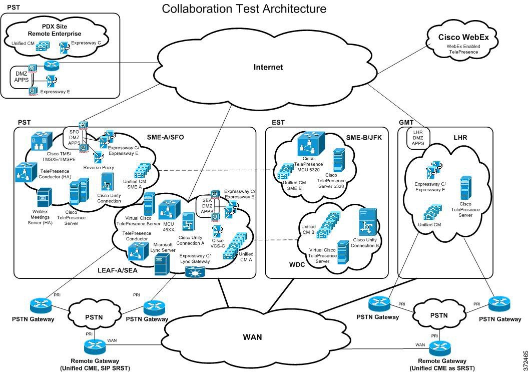
This test topology diagram depicts a high level topology centered on the Cisco Unified Communications Manager (Unified CM) call processing. The topology contains Collaboration elements that are spread across multiple time zones and geographical boundaries to address the needs of a global customer.
Typical to very large customers, the topology has a Unified CM as a session manager utilizing Cisco Unified Communication Manager Session Management Edition (Unified CM SME) feature content. The Unified CM SME is an 8 subscriber node cluster with one half of the nodes in JFK (East Coast Data Center) and another half of the nodes in SFO (West Coast Data Center) leveraging a Clustering over WAN (CoW) mechanism. Unified CM SMEs provide inter-connectivity services among various Unified CM clusters, Cisco Unified Communications Manager Express (Unified CME) nodes, and other components. There are also many SIP trunk connectivity arrangements and H.323 trunks to accommodate various testing needs.
The Unified CM SME sites serves as egress point from a Business to Business (B2B) perspective Cisco VCS Expressway-E (in DMZ) and Expressway-C nodes connected to Unified CM SME provides B2B capabilities (Voice/Video and IM and Presence). Endpoints off a main enterprise can reach out to a midmarket enterprise via B2B. The mid-market enterprise site also has its own VCS Expressway-E and C pair for B2B purposes.
Centralized IP PSTN connectivity to SIP Service Provider is provided to various clusters through Unified CM SME and Cisco Unified Border Element (Unified Border Element). Each of the clusters also has local PSTN connectivity configured. The IP PSTN connectivity from Unified Border Element to service provider uses SIP/UDP. Different types of PSTN Gateway connectivity arrangements reflect a cross section of customer gateway deployments.
The North America Seattle (SEA)/Washington DC (WDC) mega cluster has 16 subscriber nodes in a CoW. This cluster has SCCP and SIP endpoints. There are no H.323 endpoints in the SEA/WDC cluster. This site includes messaging capabilities leveraging Unity Connection, and direct and adhoc conferencing capabilities using Cisco TelePresence MCU (MCU), Cisco TelePresence Conductor and Cisco TelePresence Server (virtual).
All the H.323 and third party endpoints are placed in Cisco Video Communication Server (Cisco VCS) control leaf cluster associated with SEA/WDC. Conductor based conferencing components located at SEA also support multi-way conferencing from Cisco VCS-C Leaf Cluster. The Cisco VCS Expressway serving as a Lync gateway provides voice/video connectivity to the Cisco UC Integration™ for Microsoft Lync server to facilitate Lync Interoperability. The Lync Gateway provides necessary transcoding.
In EMEA, LHR (London Heathrow) is a medium sized cluster with two subscriber nodes. Cisco Unity Connection, connected to Unified CM SME at SFO through SIP trunking, provides voice mail support for the LHR cluster.
The endpoints in SEA/WDC and LHR clusters can be located on-premise, in remote branch offices, or in the Internet. Remote endpoints located in the Internet can ingress via two mechanisms: VPN access via AnyConnect VPN or VPN less access via Collaboration Edge.
Endpoints can also be located in remote Cisco Unified Survivable Remote Site Telephony (Unified SRST) branch offices. Two types of SRST branches are deployed in the topology: SIP-Unified SRST and Unified CME-as-Unified SRST. The SRST branches have the advantage in that the endpoint even if they encounter a loss in WAN connectivity to respective Unified CM cluster, can still survive because call control in such a scenario is provided by the SRST node.
Some endpoints are also located in small branch offices based on Unified CME.
In addition to adhoc conferencing support at SEA CUCM, the test topology also supports TelePresence Conductor based rendezvous and direct scheduled conferencing functionalities at JFK SME. Rendezvous conferencing allows a multitude of collaboration meeting rooms to be setup. Rendezvous conferencing leverages Cisco TelePresence Conductor, Cisco TelePresence Server (virtual), Cisco TMS, Cisco TMSPE and Cisco TMSXE. Direct scheduled conferencing at SME leverages Cisco TelePresence Server, MCU, Cisco TMS, Cisco TMSPE and Cisco TMSXE. The test topology is integrated into Cisco WebEx (WebEx) which allows Cisco WebEx Enabled TelePresence scenarios to be validated. Expressway-E (in DMZ) and Expressway C pair provides connectivity to WebEx Cloud as well. Cisco TelePresence endpoints located across the clusters described above may join scheduled WebEx conferences. The endpoints that participate in rendezvous and scheduled conferencing scenarios can come from a variety of locations, including but not limited to endpoints behind Expressway-E/C for remote and mobile worker access nodes.
 Feedback