Shared Cisco Meeting Server

Shared Cisco Meeting Server Configuration

Cisco Unified Communications Manager supports ad-hoc conferencing in a shared Cisco Meeting Server (CMS) environment. Ad-hoc Conferencing allows the conference controller, or a participant of the conference to add participants to the conference on the go. In other words, Ad-hoc Conferencing is an unscheduled escalation of a point-to-point call to a multi-party conference. For example, in a call between two participants, a participant in the call can use the Conference button to include a third participant in the conversation to create a three-party conference.


Note

The steps followed to start an ad-hoc conference may vary depending on the CUCM endpoint. For example, Cisco Jabber or a physical phone.


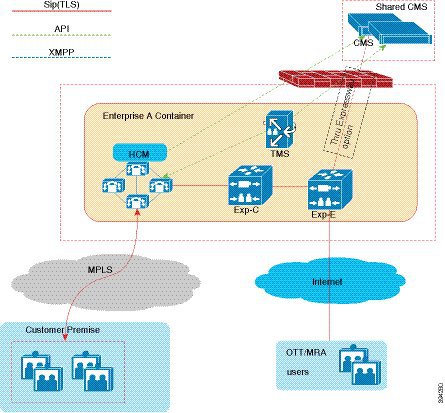
The CMS is configured in the service provider network, while the Cisco TelePresence Management Suite (TMS) Server is hosted in each customer network. Cisco Unified Communications Manager provides CMS-based video and audio conferencing capability, and ad-hoc conferencing.

The Cisco Unified Communications Manager configuration of an ad-hoc call varies significantly when compared to a scheduled conference call. In an ad-hoc conference call, when the conference initiator presses the Conference button to include all the participants in the conference, the Cisco Unified Communications Manager starts an API call to the CMS to create a conference immediately, to which all the calls of the participants are transferred. To support Ad-hoc conferencing, the Cisco Unified Communications Manager must have the following:

  • API credentials

  • Web Administrator address or port configured

  • SIP trunk that is configured directly to the CMS server.


    Note

    The Cisco Unified Communications Manager clusters must be configured with direct SIP trunks to each CMS node. During conference calls, the Cisco Unified Communications Manager dynamically creates a space on CMS, and then matches the calls that are extended to CMS against an incoming call rule for spaces.


Initial Configuration

Procedure

  Command or Action Purpose
Step 1

Install Cisco Meeting Server in Extranet or the management network.

See Cisco Meeting Server Configuration Guides for detailed instructions.

Step 2

Configure the network interface.

Example:

ipv4 a add 10.0.102.51/24 10.0.102.1
Step 3

Configure QoS.

Example:

dscp 4 multimedia 0x22 
dscp 4 multimedia-streaming 0x22 
dscp 4 voice 0x2E dscp 4 signaling 0x1A 
dscp 4 low-latency 0x1A
Step 4

Configure NTP.

Example:

ntp server add 192.168.30.129
ntp server add 192.168.31.129
Step 5

Configure TimeZone.

Example:

timezone America/New_York

.
Step 6

Generate certificate in CMS Server.

Example:

pki csr: sharedcms
CN: shared-cms.hcsprovider.com 
subjectAltName: shared-cms.hcsprovider.com,hcsprovider.com,conf.hcsprovider.com
The following files are generated:
  • sharedcms.csr

  • sharedcms.key

What to do next

Sync and upload the CSR certificate to the CMS server.

CMS Configuration

Procedure

  Command or Action Purpose
Step 1

Configure WebAdmin.

Example:

webadmin certs sharedcms.key sharedcms.cer certnew.cer

webadmin listen a 8443

webadmin restart

webadmin status

The Web Admin provides graphical user interface (GUI) for basic configuration tasks and monitoring. The WebAdmin configuration allows API access required for the advanced configuration tasks and ad-hoc conference bridging with Cisco Unified Communications Manager.

Note 
The WebAdmin must be enabled on all the CMS servers.
The REST API access is enabled.
Step 2

Configure Call Bridge.

Example:

callbridge certs sharedcms.key sharedcms.cer certnew.cer

callbridge listen a

callbridge restart

callbridge

The Call Bridge is the main conferencing engine and is enabled in every CMS deployment. It also allows licensing the CMS servers. Call Bridge provides the SIP interface for calls to be routed to and from it from external call control, such as the Cisco Unified Communications Manager. For more information, see Configure Cisco Meeting Server Call Bridge Database Cluster.

Step 3

Install CMS licenses.

Example:

shared-cms> ipv4 a
IPv4 configuration:

address 10.0.102.51

default true

dhcp false

enabled true

gateway 10.0.102.1

macaddress 00:50:56:AE:4E:04

prefixlen 24

The MAC address is used to generate the license.

Step 4

Configure API user.

Example:

shared-cms> user add apiadmin api 
Please enter new password: <Enter the password> 
Please enter new password again: <Enter the password again> 

The SUCCESS message is displayed after the successful creation of API user.

Step 5

Allow Media Encryption.

Configuring Cisco Unified Communication Manager for CMS Integration

Procedure


Step 1

Create SIP Trunk Security Profile.

  1. Open a web browser.

  2. Enter the following URL in the address bar:https://<CUCM IP Address>/ccmadin/showHome.do

  3. Log in to Cisco Unified Communications Manager using the admin credentials.

  4. Choose System > Security > SIP Trunk Security Profile.

  5. Click Add New.

  6. In the Name field, enter Encrypted SIP Trunk Profile for CMS1.

  7. From the Device Security Mode drop-down list, choose Encrypted.

    The Incoming and Outgoing Transport Type is changed to TLS.
  8. In the X.509 Subject Name field, enter all the Call Bridge FQDNs.

    Example:

    cms1a.pod2.cms.lab,cms1b.pod2.cms.lab,cms1c.pod2.cms.lab

    These are the SubjectAlternateNames that are specified in the Call Bridge certificates, which are specified so that the same SIP Trunk Security profile is used for all the SIP Trunks of each CMS.

    Note 

    You can verify the SubjectAlternateNames in CMS MMP by enter the following command: pki inspect certname.cer

  9. In the Incoming Port field, enter 5061.

  10. Check the Accept replaces header check box.

    For effective usage of CMS, the CMS uses the Replaces method in SIP to redirect calls from one CMS to the other.

  11. Click Save.

The SIP Trunk Security Profile allows encrypted calls, which ensures a secure SIP trunk.

Step 2

Configure the SIP trunk.

  1. Log in to Cisco Unified Communications Manager.

  2. Choose Device > Trunk.

  3. Click Add New.

  4. From the Trunk Type, drop-down list, choose SIP Trunk.

  5. Click Next.

  6. Configure the parameters.

    Example:

    Parameter

    Value

    Device Name

    CMS1A-SIP-TRUNK

    Device Pool

    Default

    SRTP Allowed

    Checked

    Run On All Active Unified CM Nodes

    Checked

    Calling Search Space (under the Inbound Calls section)

    CSS_INBOUND_CMS

    Note 

    This Calling Search Space is used to limit the calls that originate from CMS. The CMS can call other video endpoints, but does not have PSTN access in this deployment to avoid potential toll fraud issues.

    Calling and Connected Party Info Format

    Deliver URI and DN in connected party, if available

    Destination

    cms1a.pod2.cms.lab

    You can only configure one destination per trunk because the trunk will also be used for the ad-hoc conferencing feature. The Cisco Unified Communications Manager sends an API message to a specific Call Bridge server and then use a SIP trunk that can only reach that specific server the trunk.

    Note 

    By default, there is a single line to enter the Destination parameter. If there are16 blank lines, it could be due to browser issues. Use the - button to remove the additional lines before saving the SIP trunk.

    Destination Port

    5061

    SIP Trunk Security Profile

    Encrypted SIP Trunk Profile for CMS1

    Rerouting Calling Search Space

    CSS_CMS_REROUTING

    SIP Profile

    LTRCOL-2250 SIP Profile

    Normalization Script

    cisco-meeting-server-interop

  7. Click Save.

  8. Click OK.

  9. Click Reset.

    The changes are saved. The Device Reset dialog box is displayed.
  10. In the Reset dialog box, click Reset.

  11. Click Close.

    If you choose Device > Trunk in Cisco Unified Communications Manager administration, and click Find, you can see the trunks are in service when the SIP OPTIONS messages are answered. This might take a few minutes.

    Note 

    The admin page may report that the SIP OPTIONS are not enabled until it goes to Full service.

  12. After successful configuration, ensure the trunk status is up.

Step 3

Configure ad-hoc conference bridge for CMS server in Cisco Unified Communications Manager.

  1. Log in to Cisco Unified Communications Manager with admin credentials.

  2. Choose Media Resources > Conference Bridge.

  3. Click Add New.

  4. From the Conference Bridge Type drop-down list, choose Cisco Meeting Server.

  5. In the Conference Bridge Name field, enter CFB_CMS1A.

  6. In the Conference Bridge Prefix field, enter 1001.

    The Conference Bridge Prefix is a prefix that Cisco Unified Communications Manager uses when creating the Spaces for ad-hoc conferences on CMS. Cisco Unified Communications Manager creates a randomly generated meeting number for each ad-hoc conference. But if there are multiple Cisco Unified Communications Manager clusters using the same CMS for ad-hoc conferences, there's a possibility two clusters may have the same ID. To avoid this, the value specified in this parameter is prefixed to the randomly generated number and the resulting value is used to generate the meeting ID on CMS. We recommend that you use unique values for each conference bridge resource that is created. Unique values also help in troubleshooting by allowing you to identify the Cisco Unified Communications Manager cluster that created a particular conference in the CMS.

  7. From the SIP Trunk drop-down list, choose CMS1A-SIP-TRUNK.

    By default, this configuration determines the SIP trunk that is used to route the SIP calls to CMS and the destination for API messages. The destination address configured on the SIP trunk is used as the HTTPS destination for API messages.

  8. Check the Allow Conference Bridge Control of the Call Security Icon check box.

    This indicates to the participants whether other participants in the conference are using media encryption.

  9. In the User Name field, enter apiadmin.

    The HTTPS Interface Info section allows you to configure the authentication and port information for the API.

  10. In Password field, enter a password to set the password.

  11. In Confirm Password field, enter the password again to confirm the password.

  12. The HTTPS port must match the CMS Web Admin listening port: 8443.

    All communications must be over HTTPS, which is a secure protocol. The CMS certificates that are loaded on the Cisco Unified Communications Manager so that the Cisco Unified Communications Manager trusts the certificates presented by CMS.

    Note 

    The CMS certificates are pre-loaded on the Cisco Unified Communications Manager cluster.

  13. Click Save.

  14. Click Reset.

    A dialog box is displayed.
  15. In the dialog box, click Reset.

  16. Click Close.

  17. Wait for 30 seconds and reload the page.

    The Conference Bridge device displays Registered status.

The conference bridge resource is configured on the Cisco Unified Communications Manager cluster as cms1a.

Step 4

Configure Ad-hoc Conference Bridge Resource Group or List for CMS server in Cisco Unified Communications Manager.

  1. Log in to Cisco Unified Communications Manager.

  2. Choose Media Resources > Media Resource Group.

  3. Click Add New.

  4. In the Name field, enter MRG_CMS1 .

  5. From the Available Media Resources drop-down list, choose CFB_CM1A, and then click the arrow below the list.

    The CFG_CM1A media resource is added to the Selected Media Resources field.
  6. Repeat Step 4.e to add CFG_CM1B and CFG_CM1Cto the Selected Media Resources dialog box.

  7. Click Save.

  8. Choose Media Resources > Media Resources Group List.

  9. Click Add New.

  10. In the Name field, enter MRGL_CMS1.

  11. From the Available Media Resources Groups drop-down list, choose MRG_CMS1.

  12. From the Available Media Resources drop-down list, choose MRG_CMS1, and then click the arrow below the list.

    The MRG_CMS1 media resource is added to the Selected Media Resources field.
  13. Click Save.

The Cisco Unified Communications Manager is configured to make it available for users. By default, any device that is not assigned to a Media Resource Group (MRG) is available to all the users. However, we recommend that you assign media resources to an MRG and Media Resource Group List (MRGL), and then use the list to control how those resources are used.

Step 5

Assign MRGL to the allowed devices.

  1. Choose System > Device Pool.

  2. Click Find.

  3. Click Default Device Pool.

  4. From the Media Resource Group List, choose MRGL_CMS1.

  5. Click Save.

  6. Click Reset for the changes to take effect.

    A dialog box is displayed.
  7. In the dialog box, click Reset.

  8. Click Close to close the dialog box.

Note 

The MRGL can be assigned to a device directly. However, we recommend you to assign the MRGL to a Device Pool to ensure that the MRGL is available to all the devices in the Device Pool.

Step 6

Upload the CMS Signed Certificate to Call Manager - Trust.

See CMS Configuration Guides.