Dial Plan Management

Dial Plan Example Workflow

Dial plan procedures available in Cisco Unified Communications Domain Manager 10.6(1) are found in this section. However, additional procedures and more detailed information about dial plans can be found in Cisco Hosted Collaboration Solution, Release 10.6(1) Dial Plan Management Guide for Cisco Unified Communications Domain Manager, Release 10.6(1).

Procedure
    Step 1   Apply customer dial plan at customer.
    Step 2   Apply site dial plan at site.
    Step 3   Optionally, configure Class of Service at site.
    Step 4   Add Directory Number Inventory at customer.
    Step 5   If not using Site Location Codes (that is, you have deployed a Type 4 Dial Plan), configure Directory Number Routing at site to enable intra- and inter-site calls.
    Step 6   Edit Site Defaults as follows:
    1. On the Device Defaults tab, set the Default CUCDM Device CSS to an appropriate device Class of Service.
    2. On the Line Defaults tab, set the Default CUCM Line CSS to an appropriate line Class of Service.
    Step 7   For offnet PSTN call configuration, see Cisco Hosted Collaboration Solution, Release 10.6(1) Dial Plan Management Guide for Cisco Unified Communications Domain Manager, Release 10.6(1).
    Step 8   For user, phone, and line configuration, see Subscriber Management section in Cisco Hosted Collaboration Solution, Release 10.6(1) End-User Provisioning Guide.

    Create a Customer Dial Plan

    This procedure determines the type of Cisco HCS dial plan schema (Type 1 to 4) to be used, depending on how you fill in the form.


    Note


    You can have only one dial plan per customer. If you try to add a second dial plan, the dial plan will fail. Once you have created the customer dial plan, Enable CSS filtering is the only setting that you can modify.
    Procedure
      Step 1   Log in as the Customer Administrator or the Provider Administrator. For a list of the roles and tasks that can be done at each level, see Cisco Hosted Collaboration Solution Roles and Privileges.
      Step 2   Select Dial Plan Management > Customer > Dial Plan.
      Step 3   Click Add to add a Customer Dial Plan.
      Step 4   Perform one of the following:
      • If a Site Location Code is required for this customer, click the Site-Location Code (SLC) based dial plan? box, OR
      • If an SLC is not required, go to Step 8.
      Step 5   Perform one of the following:
      • To add an extension prefix for the dial plan, click the Use extension prefix? box. Enter the extension prefix in the form and go to Step 8.
      • To add an ISP for the dial plan, click the Inter-Site Prefix required for inter-site dialing? box. Enter the Inter-Site Prefix (ISP). The ISP can be one digit in length.
      Step 6   If the ISP should be included in the directory number, click the Is ISP included in directory number? box. If not, go to Step 8.
      Step 7   If the ISP should be included as part of the Voice Mail ID, click the Is ISP included in Voice Mail ID? box. If not, go to the next step.
      Step 8   Check Enable CSS filtering to filter the calling search spaces available when configuring a Subscriber, Phone, or Line, to site level Class of Service calling search spaces. Filtering is disabled by default, which results in all available Cisco Unified Communications Manager calling search spaces being available when configuring a Subscriber, Phone, or Line.
      Step 9   Click Save to add the Customer Dial Plan you defined.
      Note    The Customer ID is a unique, auto-generated, read-only number allocated to the customer. The Customer ID is particularly useful in shared deployments (where a cluster may be shared across multiple customers) to correlate specific elements to a customer. It appears in the Cisco Unified Communications Manager as an prefix to elements (for example Cu2Si7 identifies Customer 2, Site 7).

      Note    The Cisco HCS dial plan schemas are configured such that the customer-level dial plan elements are not pushed to the Cisco Unified Communications Manager until the first site for the customer is deployed. Therefore, you will not see any dial plan elements provisioned on the Cisco Unified Communications Manager until at least one site is deployed for the customer. See Create a Site Dial Plan.
      Note   

      When adding lines (DNs) at the site level, you must remember to define your DNs appropriately (that is, you are responsible for using ISP+SLC+EXT if you deploy a Type 2 dial plan). Otherwise your inter/intra site calls won’t route. To define your directory numbers, refer to Add Directory Number Inventory.


      Create a Site Dial Plan

      A site dial plan does not get created automatically for a site when a site is created. Perform this procedure to associate a site dial plan with the site. After the first site for a specific customer is deployed, the customer-level dial plan elements are provisioned on Cisco Unified Communications Manager, followed by the site-specific dial plan elements. Each subsequent site only has site-specific dial plan elements to provision, so it takes less time to create. If there is more than one site for a customer, do not forget to apply the site dial plan to each site.


      Note


      Step 13 of this procedure takes a few minutes to provision the site dial plan, especially for the first site.


      Note


      Each site can have one site dial plan only.
      Important:

      You can not edit the site dial plan once it is created. If you need to change the site dial plan, delete the current site dial plan and create a new one.

      Before You Begin

      A site dial plan cannot be created until a customer dial plan is created for the customer. There are attributes that are defined in the customer dial plan that are needed when creating a site dial plan.

      Procedure
        Step 1   Log in as the Customer Administrator or Provider Administrator. For a list of the roles and tasks that can be done at each level, see Cisco Hosted Collaboration Solution Roles and Privileges.
        Note    When adding a site dial plan, ensure that you select a valid site under your customer in the hierarchy node breadcrumb at the top of the view. If you attempt to create a site dial plan at any other node in the hierarchy, you will receive an error indicating that you must be at a site.
        Step 2   Select Dial Plan Management > Site > Dial Plan.
        Step 3   Click Add to add a Site Dial Plan.
        Step 4   Modify External Breakout Number field if desired. This is the PSTN prefix that is used when deploying a country dial plan. For Cisco HCS Type 1 to 4 dial plan schemas, you deploy country dial plans at the customer level. The country dial plan is not pushed to Cisco Unified Communications Manager until the first site associated with a given country is deployed. For example, if a site is associated with the United States of America, and it is the first site dial plan being created for the USA, the US country dial plan is deployed as part of creating the site's dial plan. Default is 9. The External Breakout Number is one digit in length.
        Note   

        Cisco supports only one External Breakout Number for each country. For example, all sites within USA have the same External break out as the first site within USA.

        Step 5   Enter the Site Location Code using a maximum of eight digits. The SLC must be unique across sites for a customer.
        Note    If the Customer Dial Plan does not user SLCs, this field does not appear.
        Step 6   Enter the Extension Length. Values can be 1 to 11. Default is 4; for example, 2000.
        Note    When adding DNs for a site, extension length is not currently enforced. Therefore, the administrator must be conscious of extension length when adding DNs for a particular site; otherwise DNs may not be dialable.
        Step 7   Perform one of the following for sites without Inter-Site Prefixes (ISPs):
        Note    This field appears if your Customer Dial Plan does not use ISPs; for example HCS Type 3 dial plans (SLC, no ISP, DN=SLC+EXT)
        • Click the Use extension prefix? box if your customer dial plan has an extension prefix defined and you would like this site to use the extension prefix, OR
        • If an Extension prefix is not defined in the customer dial plan for this site, go to the next step .
        Step 8   Enter the Area Code. Enter zero or more valid local area codes for the site. You must specify the length of the subscriber part of the PSTN number for each area code. This is used to generated the PSTN local route patterns for the site. For example, in the USA, if area codes are added for Dallas, Texas, the area codes could be specified for local dialing as 214, 469, and 972 with a subscriber length of 7.
        Step 9   Enter the Local Number Length. This is the length for the subscriber section of the entire E.164 number.
        Step 10   Click the Area Code used for Local Dialing box if the area code is needed for local dialing from this site. In the US this would determine whether you use 7 or 10 digit local dialing.
        Step 11   Enter the Published number for the site. The site published number is the default E.164 mask when a line is associated to a phone at a particular site.
        Step 12   Enter the Emergency Call Back Number for the site.

        The site emergency call back number is the calling number when initiating an outgoing emergency call. It can be used when a user is using extension mobility and making an emergency call from a site other than their own. It can be used when the emergency call goes out to the PSTN network, when the system includes the site emergency number so that the origin of the call is known. The system adds this calling party transformation to the DN2DDI4Emer-PT partition.

        Note   

        The Emergency Number is not the number to dial for an emergency. Instead, it is the number used to identify the calling party for emergency calls originating from a particular site.

        Note    Under the Emergency Number field, there is the Site ID read-only field. The Site ID is a unique, auto generated, read-only number for each customer site which is prefixed to elements as an identifier (for example Cu4Si2 indicates Customer 4, Site 2).
        Step 13   Click Save to add the Site Dial Plan you defined. The site information is loaded on the Cisco Unified Communications Manager, and is identifiable by its Customer ID, Site ID prefix.

        Configure Class of Service

        Use this procedure to create a new Calling Search Space (CSS) or edit an existing CSS that is tied to a site. The CSS can be used as a Class of Service (COS) for a device or line, or any of the other templates that rely on COS to filter different features.

        Procedure
          Step 1   Log in as the Provider, Reseller, or Customer Administrator.
          Note    When adding Class of Service, ensure that you select a valid site under the customer in the hierarchy node breadcrumb at the top of the view. If you attempt to add a Class of Service at any other node in the hierarchy, you will receive an error indicating that you must be at a site.
          Step 2   Select Dial Plan Management > Site > Class of Service.
          Note    There is one default Internal Calling Line Identification Presentation (CLIP) Class of Service that appears in the list. The default COS is provisioned automatically based on the criteria you selected when you added the site.
          Step 3   Perform one of
          • To add a Class of Service, click Add.

          • To edit an existing Class of Service, choose the COS to be updated by clicking on its box in the leftmost column, then click Edit.

          • To clone an existing Class of Service, choose the COS to be cloned by clicking on its box in the leftmost column, then click Clone.

          Step 4   Enter a unique name for the Class of Service in the Class of Service Name field. Try to make the name as descriptive as possible using up to 50 alphanumeric characters, including spaces, period(s), hyphens (-), and underscore characters (_). You can also make use of macros that are available in the system to create a Class of Service name. For a list of possible macros, refer to Macros. Macros allow you to dynamically add site IDs, customer IDs, and other types of information to the CSS.

          Example:Cu1-24HrsCLIP-PT-{{macro.HcsDpSiteName}}
          Note   

          The actual CSS that is sent to the Cisco Unified Communications Manager (based on the macros entered) is mirrored in the Actual Calling Search Space field. For example, the macro example above changes to Cu1-24HrsCLIP-PT-SiteABC.

          Step 5   Add a description for the Class of Service in the Description field if desired.
          Step 6   Choose route partition members to include in the Class of Service by performing the following:
          1. Click + to add route partitions.
          2. From the pulldown menu, select a route partition member.
          3. Repeat this step as required until you have selected all desired members for this Class of Service.
          Note   

          To remove a member from the Class of Service, click .

          Step 7   Click Save to add the Class of Service that you defined. The new Class of Service appears in the table of Classes of Service and it can be edited or deleted as required.

          Macros

          Macros can be used in Cisco Unified Communications Domain Manager 10.6(1) to dynamically add site IDs, customer IDs, and other types of information when customizing dial plan schemas and Class of Service. Macros increase ease of use and reduce error.

          Macros are evaluated within the context of a particular hierarchy node based on the scope specified in the schema group binding (for example, site, customer, provider).

          The correct syntax for a macro is the word “macro” followed by a period (.), followed by the Named Macro as shown in the table that follows. Add double curly brackets ({{ }}) around the entire macro combination. For example, {{ macro.HcsDpCustomerName }} is the macro combination created using the first Named Macro in the table.

          The following table provides a list of Named Macros currently available. This list will be expanded as new macros become available.

          Table 1 Macros Available in Cisco Unified Communications Domain Manager 10.6(1)
          Named Macro Description
          HcsDpCustomerName Name of the customer (as specified when you create your customer)
          HcsDpCustomerId Systemwide, unique internal customer ID generated when you create a customer
          HcsDpSiteName Name of the site (as specified when you create a site under a customer)
          HcsDpSiteId Systemwide, unique internal site ID generated when you create a site
          HcsDpUniqueCustomerPrefixMCR Default unique Cisco HCS customer prefix in the form 'Cu{{ macro.HcsDpCustomerId }}'
          HcsDpUniqueSitePrefixMCR Default unique HCS site prefix in the form 'Cu{{ macro.HcsDpCustomerId }}Si {{ macro.HcsDpSiteId }}'
          HcsDpSiteCountryMCR Returns the country associated with a specific site
          HcsDpSiteCountryIso Returns the ISO 3166-1 alpha-3 three-letter country code associated with the country that is associated with a specific site
          HcsDpPstnBreakout Returns the PSTN prefix digit for the country that is associated with a specific site
          HcsDpSiteAreaCodeInLocalDialingMCR Returns True if a specific site requires area code for local PSTN dialing
          HcsDpSiteNatTrunkPrefixMCR Return the national trunk prefix associated to a particular site
          HcsDpDefaultSiteDevicePoolMCR Default Cisco HCS site device pool Cisco Unified Communications Manager element name
          HcsDpDefaultSiteLocationMCR Default Cisco HCS site location Cisco Unified Communications Manager element name
          HcsDpDefaultSiteRegionMCR Default Cisco HCS site region Cisco Unified Communications Manager element name
          The following macros can be used to loop through the area codes specific for a particular site when adding translation patterns:
          HcsDpSiteAreaCodeMCR Returns list of area codes associated with a specific site
          HcsDpSiteAreaCodeItem_AreaCodeMCR Return the area code attribute from the area code list item
          HcsDpSiteAreaCodeItem_LocLenMCR Return the local number length attribute from the area code list item

          Clone a Class of Service

          Use this procedure to clone an existing Class of Service (CoS) to the same site hierarchy node with a new name.

          Procedure
            Step 1   Log in as provider, reseller, customer, or site administrator.
            Note   

            When cloning a Class of Service (CoS), ensure that you select a valid site under the customer in the hierarchy node breadcrumb at the top of the view. If you attempt to clone a Class of Service at any other node in the hierarchy, you will receive an error indicating that you must be at a site.

            Step 2   Select Dial Plan Management > Site > Class of Service.
            Step 3   Choose the Class of Service to be cloned by clicking on its box in the leftmost column.
            Step 4   Click Action > Clone.
            Step 5   Enter a unique name for the Class of Service in the Class of Service Name field. Make the name as descriptive as possible using up to 50 alphanumeric characters, including spaces, period(s), hyphens (-), and underscore characters (_).
            Step 6   (Optional) Add a description for the Class of Service in the Description field.
            Step 7   Click Save to save the new Class of Service.
            Note   

            You must save the cloned CoS to the same site hierarchy node as the original CoS. You cannot save the cloned Class of Service to a different site, or to a different hierarchy node.

            The new Class of Service appears in the table of Classes of Service and it can be edited or deleted as required.

            Configure Short Code

            Use this procedure to configure short codes. Short codes are used for abbreviated dialing to other extensions and services.

            Before You Begin

            You must add a Site Dial Plan before configuring Short Code. Refer to Create a Site Dial Plan.

            Procedure
              Step 1   Log in to the server as the Provider, Reseller, Customer, or Site Administrator.
              Note    When adding a Short Code, ensure that you select a valid site under your customer in the hierarchy node breadcrumb at the top of the view. If you attempt to add a Short Code at any other node in the hierarchy, you will receive an error indicating that you must be at a site.
              Step 2   Select Dial Plan Management > Site > Short Code.
              Step 3   Click Add to add a Short Code.
              Step 4   Enter a short code in the Short Code field using up to 16 characters with the following format:
              • The first character may be 0-9, or *.

              • The last character may be 0-9, #, or the wildcard character X.

              • All other characters may be 0-9, . (period), or the wildcard character X. Only one . (period) is allowed.


              Example:

              *2.XXX

              Step 5   From the Short Code Type dropdown menu, choose one of
              Option Description
              Called Mask

              The called mask maps to the short code. Valid entries include the digits 0 through 9; the international escape character +; and the wildcard character X. For example, a called mask of 567XXX using short code *2.123 converts to 567123.

              Directory Number

              The directory number maps to the short code. Valid entries are digits 0 through 9.

              Pre-dot with Called Prefix

              The called prefix maps to the short code

              Step 6   Enter the value for the Short Code Type in the Value field.
              Step 7   Check the Use Originator's Calling Search Space check box to indicate that the short code will use the originator's calling search space for routing a call rather than an explicit customer CSS.

              If the originating device is a phone, the originator's calling search space is a combination of the device calling search space configured on their phone and line calling search space configured on the originating line.

              Step 8   Click Save to add the Short Code that you defined. The new Short Code appears in the table of Short Codes and it can be edited or deleted as required.

              Number Management

              E164 Inventory Management

              E.164 Inventory Management provides Direct Dial-In (DDI)/Direct Inward Dialing (DID) mapping to Directory Numbers (DN) using translation patterns in the Cisco Unified Communications Domain Manager. The DDI-to-DN mapping allows you to route incoming PSTN calls to the appropriate internal directory number.

              E.164 Inventory Management includes the ability to:
              • Add, view, and delete E.164 number inventory

              • Associate a range of E.164 numbers to a range of DNs

              • View associated range of E.164 numbers to a range of Directory numbers

              • Disassociate a range of E.164 numbers from a range of DNs

              • Associate a range or set of E.164 numbers to a single DN

              • Disassociate a range or set of E.164 numbers from a single DN

              • View single Directory number associations

              The E.164 inventory is available in the dropdown menus for Site Published Number and Emergency Number when creating a Site Dial Plan.

              Add E164 Inventory

              Use this procedure to define an inventory of E.164 numbers available to end users at a site.

              Important: Each addition to the E.164 Inventory must contain a unique set of numbers. That is, you cannot assign the same number more than once (globally).
              Procedure
                Step 1   Login as provider, reseller, or customer admin.
                Step 2   Set the hierarchy path to point to the customer for whom you are adding the E.164 inventory.
                Step 3   Select Dial Plan Management > Number Management > Add E164 Inventory.
                Step 4   Provide the following information:
                Fields Description
                Site

                Select the customer site for which you are adding the E.164 inventory. This field is mandatory.

                Starting Number

                Enter the starting number of the range of E.164 numbers. The field is populated with + followed by the country code associated with the selected site. Append the rest of the starting number after the country code. This field is mandatory.

                Ending Number Enter the ending number of the range of E.164 numbers. The format is the same as the Starting Number. This field is optional. If not provided, the single E.164 Number specified in the Starting Number will be added. If provided, the range of E.164 Numbers is added: Starting Number – Ending Number, inclusive. A maximum of 1000 numbers can be added at a time.
                Country Code

                The country code associated with the site. This field is read only and is for your reference because the Starting Number field and Ending Number field must contain a valid country code or else the E.164 inventory items will not be added successfully.

                Step 5   Click Save.

                View E164 Number Inventory

                Use this procedure to view the inventory of E164 numbers.

                Procedure
                  Step 1   Login as provider, reseller, customer, or site admin.
                  Step 2   Set the hierarchy path to limit the scope of E.164 numbers being viewed.
                  Step 3   Select Dial Plan Management > Number Management > E164 Inventory.

                  A table containing the following information is displayed:

                  Column Description
                  E164 Number

                  The individual E.164 number in the inventory.

                  Associated Flag

                  Indicates the E.164 number has been associated with a Directory Number

                  Hierarchy

                  Indicates the hierarchy of the site the E.164 number was created for.


                  Delete E164 Numbers from Inventory

                  Use this procedure to delete numbers from the E.164 inventory.


                  Note


                  You cannot delete E.164 numbers that are currently associated with a Directory Number.
                  Procedure
                    Step 1   Login as provider, reseller, or customer admin.
                    Step 2   Set the hierarchy path to limit the scope of E.164 numbers being deleted.
                    Step 3   Select Dial Plan Management > Number Management > E164 Inventory.
                    Step 4   Perform one or both of the following:
                    • To delete an individual number, click the number, then click Delete.
                    • To delete multiple E.164 numbers, click the checkbox next to each number you want to delete, then click Delete. Use column filtering to narrow and refine the list of items to select for a batch delete.
                    Step 5   Click Yes in the confirmation window.

                    Add Directory Number Inventory

                    Use this procedure to add a single directory number (DN) or range of DNs for your customer. The DNs (extensions) you specify are validated against the Dial Plan type (Type 1 to 4). The extension length assigned to the site is enforced for site location code (SLC)-based dial plans. The maximum number of directory numbers you can add at a time is 1,000. For more information on Type 1 to Type 4 dial plans, see Directory Numbers.

                    If you are a customer with multiple sites and are using a Type 4 dialing plan, ensure that the directory numbers you specify are unique across sites.


                    Note


                    This procedure only creates the DN inventory in Cisco Unified Communications Domain Manager 10.6(1). The numbers are not passed on to Cisco Unified Communications Manager.


                    Note


                    Directory numbers can only be added or deleted. You cannot edit the directory numbers once they are added. The usage and availability property for each DN is associated with a line or taken into use by a service.


                    Before You Begin

                    You must deploy a customer and/or site dial plan before performing this procedure.

                    Procedure
                      Step 1   Log in as the Provider, Reseller, or Customer Administrator.
                      Step 2   Select an available Customer from the hierarchy node breadcrumb at the top of the interface.
                      Step 3   Select Dial Plan Management > Number Management > Add Directory Number Inventory.
                      Step 4   From the Site dropdown menu, select the site for which you are adding directory numbers. Leave this field empty to add customer level directory numbers.
                      Note   

                      Customer level directory numbers can only be created for dial plans that do not use site location codes (flat dial plans). Attempting to create customer level directory numbers for site location code based dial plans result in an error instructing the administrator to specify a site when adding new DN inventory.

                      Step 5   Using the Extension Length, Site Location Code, and ISP read-only fields as a guide for the site, enter the first number for the DN range in the Starting Extension field.
                      Note   

                      For a Type 4 dial plan (no SLCs), the Starting and Ending Extension fields must contain no more than 16 digits each, including the + sign before the DN number, if used. For Types 1 to 3 dial plans, the Starting and Ending Extension fields must be less than or equal to the site Extension Length. If the Starting or Ending Extension field length is less than the site Extension Length, the DN number will be padded with zeroes until its length equals that of the site Extension Length.


                      Example:If the Extension Length field shows four digits for a Type 3 Dial Plan, ensure that you enter a number containing four digits or less in the Starting Extension field. For example, DN 1234. If you enter DN 123, the extension number will be created as DN 0123.
                      Step 6   (Optional) Using the Extension Length, Site Location Code, and ISP read-only fields as a guide for the site, enter the last number for the DN range in the Ending Extension field. If you are adding a single DN, the ending number is the same as the starting number.
                      Note   

                      The maximum number of directory numbers you can add is 1,000 at a time. If you need more than 1,000 directory numbers, repeat this procedure as required to add ranges.

                      Step 7   Click Save to save the single DN or DN range.
                      Note    You can verify that the directory number or numbers were added correctly by navigating to Dial Plan Management > Number Management > Directory Number Inventory.

                      View Directory Number Inventory

                      Use this procedure to view the range of directory numbers that have been defined for a site.

                      Procedure
                        Step 1   Log in as the Provider, Reseller or Customer Administrator.
                        Step 2   Select an available site from the hierarchy node breadcrumb at the top of the interface.
                        Step 3   Select Dial Plan Management > Number Management > Directory Number Inventory. The list of all directory numbers (DNs) configured for the site appears. You can view the list of DN numbers or delete a DN number from this page. To filter the list of directory numbers, click the up arrow beside the title of the Internal Number column. Enter the Search String you want to locate, and all directory numbers that match the search string appear.

                        When a DN is first added to the inventory, the Used column is blank, and the Available column shows "true". The Used column changes to "true" when the DN is put into use when a line is created and associated to a phone or subscriber. The Available column indicates that the DN is put into use by a device or service that does not allow a shared line (for example, a Hunt Pilot).

                        Note   

                        Adding a new DN to inventory on Cisco Unified Communications Domain Manager 10.6(1) does not add a directory number on Cisco Unified Communications Manager until it is associated to a line on Cisco Unified Communications Domain Manager 10.6(1).

                        The Directory Number Inventory entries appear in other end-user provisioning tasks in Cisco Unified Communications Domain Manager 10.6(1) as described in the table that follows. For more information on provisioning each of these tasks, refer to Cisco Hosted Collaboration Solution, Release 10.6(1) End-User Provisioning Guide.

                        Task

                        Cisco Unified Communications Domain Manager 10.6(1) Location

                        Notes

                        Lines

                        Subscriber Management > Lines

                        When lines are added through phones and subscriber, line details can be modified.

                        The DN for the line cannot be modified; if you attempt to change the DN assigned to the line, the operation will fail.

                        Phones

                        Subscriber Management> Phones> Lines tab> Dirn> Pattern

                        The Dirn> Pattern contains a list of available directory numbers.

                        DNs that are in use are marked as "true" in the Directory Number Inventory.

                        Only available DNs are listed.

                        Subscribers

                        Subscriber Management> Subscribers >Phones> Lines> Dirn

                        The Dirn> Pattern contains a list of available directory numbers.

                        DNs that are in use are marked as "true" in the Directory Number Inventory.

                        Only available DNs are listed.

                        Subscriber Management> Subscribers >Voicemail>

                        The "Voicemail Line" list contains DNs provisioned to lines.

                        Quick Add Subscribers

                        Subscriber Management > Quick Add Subscriber > Lines > Directory Number

                        The Directory Number list contains available directory numbers.

                        DNs that are in use are marked as "true" in the Directory Number Inventory.

                        Only available DNs are listed.

                        PLAR (Hotdial)

                        Subscriber Management > PLAR (Hotdial)

                        DNs provisioned to lines are displayed in the Hotdial Destination Pattern list

                        Hunt Groups Subscriber Management > Hunt Groups > Members> Directory Number > DNs provisioned to lines are displayed in the Pattern list
                        Call Pickup Groups Subscriber Management > Call Pickup Groups > Call Pickup Group > Line DNs provisioned to member lines are displayed in the Pattern list

                        Directory Numbers

                        The Cisco HCS dial plan enables the creation of directory numbers (Cisco Unified Communications Manager Internal DNs) with the following choices of characteristics:

                        Table 2 Dial Plan Classification
                        Dial Plan Configuration Type Site Location Code (SLC) IDP (Inter Site Prefix (ISP)) IDP in DN Extension Dialing Prefix (EDP) Extension Format
                        1 Yes Yes No unnecessary with ISP SLC + Ext, No ISP in SLC
                        2 Yes Yes Yes unnecessary with ISP ISP+SLC+Ext (ISP is part of SLC)
                        3 Yes No No Yes/No SLC+Ext and no ISP, can be with or without EDP
                        4 No No No Not Applicable Ext (Flat Dial Plan/ no SLC)

                        The specific terminology used above is explained in detail in the sections that follow.

                        Delete Site Directory Numbers

                        Use this procedure to delete one or more directory numbers at a site. You can bulk delete all directory numbers at a site using this procedure, or you can delete all directory numbers at a site automatically when you delete the site.

                        Procedure
                          Step 1   Log in at any level. Select an available site from the hierarchy node breadcrumb at the top of the view if you are not at the Site level.
                          Step 2   Select Dial Plan Management > Number Management > Directory Number Inventory.
                          Step 3   From the list of directory numbers, choose the directory number(s) to be deleted, by clicking on one or more boxes in the leftmost column. To bulk delete all directory numbers at the site, click the box at the top of the leftmost column. To filter the list of directory numbers, click the up arrow beside the title of the Internal Number column. Enter the Search String you want to locate for deletion.
                          Step 4   Click Delete to delete the directory number(s).
                          Step 5   From the popup window, click Yes to confirm the deletion. When the delete action is complete, the directory number(s) disappears from the list.

                          Associate Range of E164 Numbers to a Range of Directory Numbers

                          Use this procedure to associate a range of E.164 numbers with a range of Directory numbers (DN) at a site. These associations create Discard Digits Instruction (DDI) associations so that incoming PSTN numbers are routed to directory numbers.


                          Note


                          Only DNs or E.164 numbers that are not currently associated are available for association.


                          Procedure
                            Step 1   Login as provider, reseller, customer or site admin.
                            Step 2   Set the hierarchy path to point to the site where a range of E.164 numbers is to be associated with a range of directory numbers.
                            Step 3   Select Dial Plan Management > Number Management > E164 Associations (N to N DN).
                            Step 4   Click Add.
                            Step 5   Provide the following information:
                            Field Description
                            Range
                            Select one of the following ranges from the dropdown menu:
                            Note   

                            The range values you select map to the mask value when the association translation pattern is created. For example, when 10 is selected, all E.164 numbers and directory numbers that end in 0 are listed because the mask affects all digits 0 through 9, so you can't start the mask on a non-zero number. Likewise, when 100 is selected, the E.164 number and DN end in two zeros; this results in a mask of XX.

                            • 1—To list all E.164 numbers and DNs

                            • 10—To list all E.164 numbers and DNs that end in one zero (0)

                            • 100—To list all E.164 numbers and DNs that end in two zeros (00)

                            • 1000—To list all E.164 numbers and DNs that end in three zeros (000)

                            This field is mandatory and affects what appears in the fields below.

                            E164 Number

                            Select the starting number of the range of E.164 numbers from the dropdown menu. The field includes a + followed by the country code associated with the selected site, followed by the rest of the starting number after the country code. This field is mandatory.

                            DN Number Select the starting extension number from the dropdown menu. This field is mandatory.
                            Step 6   Click Save. A translation pattern is created on the Cisco Unified Communications Manager which is used to route inbound PSTN calls to their associated DN. This is the mapping between the E164 range and DN range.

                            View Associated Range of E164 Numbers to a Range of Directory Numbers

                            Use this procedure to view the ranges of E.164 numbers that are associated with a range of Directory numbers (DN).

                            Procedure
                              Step 1   Login as provider, reseller, customer, or site admin.
                              Step 2   Set the hierarchy path to the site where the E.164 numbers and Directory numbers are associated.
                              Step 3   Select Dial Plan Management > Number Management > E164 Associations (N to N DN).

                              A table containing the following information is displayed:

                              Column Description
                              E164 Number

                              The starting E.164 number in the range

                              DN Number

                              The starting Directory number in the range

                              Range
                              One of the following:
                              • 1—To indicate that a single E.164 number and DN are associated

                              • 10— To indicate that a range of 10 numbers including the starting E.164 and starting DN are associated

                              • 100— To indicate that a range of 100 numbers including the starting E.164 and starting DN are associated

                              • 1000—To indicate that a range of 1000 numbers including the starting E.164 and starting DN are associated

                              Hierarchy

                              Indicates the hierarchy of the site where the E.164 number range and DN range association was created


                              Disassociate Range of E164 Numbers from a Range of Directory Numbers

                              Use this procedure to disassociate a range of E.164 numbers from a range of Directory numbers (DN).

                              Procedure
                                Step 1   Login as provider, reseller, customer, or site admin.
                                Step 2   Set the hierarchy path to the site where the E.164 numbers and Directory numbers are associated.
                                Step 3   Select Dial Plan Management > Number Management > E164 Associations (N to N DN).

                                An E164 Associations (N to N DN) table containing the following information is displayed:

                                Column Description
                                E164 Number

                                The starting E.164 number in the range

                                DN Number

                                The starting DN number in the range

                                Range
                                One of the following:
                                • 1—To indicate that a single E.164 number and DN are associated

                                • 10— To indicate that a range of 10 numbers including the starting E.164 and starting DN are associated

                                • 100— To indicate that a range of 100 numbers including the starting E.164 and starting DN are associated

                                • 1000—To indicate that a range of 1000 numbers including the starting E.164 and starting DN are associated

                                Hierarchy

                                Indicates the hierarchy of the site where the E.164 number range and DN range association was created

                                Step 4   Perform one of the following:
                                • To disassociate multiple ranges of E.164 numbers and DNs at one time, click the check box in the leftmost column of the E164 Associations (N to N DN) table, beside the ranges to be disassociated. Click all that apply.
                                • To disassociate a single range of E.164 numbers and DNs, click on its row in the E164 Associations (N to N DN) table. The details about the association appear.
                                Step 5   Click Delete.
                                Step 6   From the popup, click Yes to confirm the disassociation, or click No to retain the association. The translation pattern mapping between the E.164 range and DN range is deleted from the Cisco Unified Communications Manager.

                                Associate Set of E164 Numbers to a Single Directory Number

                                Use this procedure to associate a set of E.164 numbers with a single Directory number (DN). For example, you may wish to associate a set of E.164 numbers for the Sales department with an Attendant's directory number.


                                Note


                                Only DNs or E.164 numbers that are not currently associated are available for association.


                                Procedure
                                  Step 1   Login as provider, reseller, customer or site admin.
                                  Step 2   Set the hierarchy path to point to the site where a set of E.164 numbers is to be associated with a single DN.
                                  Step 3   Select Dial Plan Management > Number Management > E164 Associations (N to 1 DN).
                                  Step 4   Click Add.
                                  Step 5   From the DN Number dropdown menu, select a single extension number. This field is mandatory.
                                  Step 6   In the E164 Ranges table, click + as required, to add multiple sets of E.164 numbers. The E.164 numbers do not need to be contiguous. Provide the following information for each association:
                                  Field Description
                                  E164 Range
                                  Select one of the following sets from the dropdown menu:
                                  • 1—To list all E.164 numbers

                                  • 10—To list all E.164 numbers that end in one zero (0)

                                  • 100—To list all E.164 numbers that end in two zeros (00)

                                  • 1000—To list all E.164 numbers that end in three zeros (000)

                                  This field is mandatory and affects what appears in the field below.

                                  E164 Number

                                  Select the starting number of the set of E.164 numbers from the dropdown menu. The field includes a + followed by the country code associated with the selected site, followed by the rest of the starting number after the country code. This field is mandatory.

                                  Step 7   Repeat the previous step as required until all E.164 associations for the single DN are complete.
                                  Step 8   Click Save. One or more translation patterns are created on the Cisco Unified Communications Manager that is used to route inbound PSTN calls to their proper DN. This is the mapping between the set of E.164 numbers and the single Directory number. When you associate a set of E.164 numbers to a single DN, multiple translation patterns are created; that is, each DN-to-E164 range association results in a translation pattern being created on Cisco Unified Communications Manager.

                                  View E164 Set-to-Single Directory Number Associations

                                  Use this procedure to view the sets of E.164 numbers that are associated with a single Directory number (DN).

                                  Procedure
                                    Step 1   Login as provider, reseller, customer, or site admin.
                                    Step 2   Set the hierarchy path to the site where the Directory number and E.164 numbers are associated.
                                    Step 3   Select Number Management > E164 Associations (N to 1 DN).

                                    A table containing the following information is displayed:

                                    Column Description
                                    DN Number

                                    The associated Directory number

                                    Hierarchy

                                    Indicates the hierarchy of the site where the E.164 number range and DN association was created

                                    Step 4   Click on an associated Directory Number in the table to select it. Details about the sets of E.164 numbers that are associated with the Directory Number appear in read-only format.

                                    Disassociate E164 Set from a Single Directory Number

                                    Use this procedure to disassociate a set of E.164 numbers from a single directory number. When you disassociate a set of E.164 numbers from a single DN, multiple translation patterns are deleted; that is, each DN-to-E.164 set association results in a translation pattern being deleted from Cisco Unified Communications Manager.

                                    Procedure
                                      Step 1   Login as provider, reseller, customer, or site admin.
                                      Step 2   Set the hierarchy path to the site where the E.164 numbers and Directory number is associated.
                                      Step 3   Select Dial Plan Management > Number Management > E164 Associations (N to 1 DN).

                                      An E164 Associations (N to 1 DN) table containing the following information is displayed:

                                      Column Description
                                      DN Number

                                      The DN number

                                      Hierarchy

                                      Indicates the hierarchy of the site where the E164 number range and DN range association was created

                                      Step 4   Perform one of the following:
                                      • To disassociate multiple associations at one time, click the check box in the leftmost column of the E164 Associations (N to 1 DN) table, beside the numbers to be disassociated. Click all that apply.
                                      • To disassociate a single association, click on its row in the E164 Associations (N to 1 DN) table. The details about the association appear.
                                      Step 5   Click Delete.
                                      Step 6   From the popup, click Yes to confirm the disassociation, or click No to retain the association. The translation pattern mapping between the E.164 set and the DN number is deleted from the Cisco Unified Communications Manager.

                                      Migrate Translation Patterns for E164-to-DN Associations

                                      If you manually configured the Translation Patterns in the E164Lookup partition to associate E.164 numbers to directory numbers for DDI routing, Cisco recommends you use the E164-to-DN Association feature for Cisco Unified Communications Domain Manager 10.1(2) (Unified CDM) and later.

                                      Use this procedure to migrate the existing Translation Patterns.

                                      Procedure
                                        Step 1   Log in to Unified CDM as a provider, reseller, or customer administrator.
                                        Step 2   Add the appropriate E.164 inventory at Dial Plan Management > Number Management > Add E164 Inventory.
                                        Step 3   View the E.164 number inventory: Dial Plan Management > Number Management > E164 Inventory.
                                        Step 4   Verify that the selected DN inventory is available for association: Dial Plan Management > Number Management > Directory Number Inventory.
                                        Step 5   Remove the previously added Translation Patterns: Device Manager > CUCM > Translation Pattern.
                                        Step 6   Create the appropriate associations using the E164-to-DN Association feature: Dial Plan Management > Number Management > E164 Associations (N to N DN). These associations restore the appropriate Translation Patterns in the E164Lookup partition for the selected customer.
                                        Step 7   View the new Translation Pattern: Device Manager > CUCM > Translation Pattern.

                                        Configure Cisco Unified Communications Manager Translation Patterns

                                        Sometimes it may be necessary to update the default dial plan translation patterns that are deployed as part of the default dial plan schemas that are delivered with the Cisco Unified Communications Domain Manager 10.6(1) template package. For example, you may want to make your default national number translation patterns more restrictive. Also, additional translation patterns could be deployed that are specific to a customer deployment. For example, customer-specific blocking patterns could be added by an administrator that are not defined in the standard country dial plan schema.


                                        Caution


                                        The Cisco HCS default dial plan includes most common translation and route patterns and in most cases, should be added automatically when a customer dial plan, site dial plan, and voice mail service is provisioned. If you wish to update translation and route patterns using Cisco Unified Communications Domain Manager 10.6(1), you must have a full understanding of the Cisco HCS dial plan. Refer to the Cisco Hosted Collaboration Solution, Release 10.6(1) Dial Plan Management Guide for Cisco Unified Communications Domain Manager, Release 10.6(1) at http:/​/​www.cisco.com/​c/​en/​us/​support/​unified-communications/​hosted-collaboration-solution-version-10-1-1/​model.html.


                                        Use this procedure to update Cisco Unified Communications Manager translation patterns that are provisioned by the dial plan schema or to add new translation patterns from Cisco Unified Communications Domain Manager 10.6(1) that are not part of the standard dial plan package. For more information on Cisco Unified Communications Manager translation patterns, refer to http:/​/​www.cisco.com/​c/​en/​us/​td/​docs/​voice_ip_comm/​cucm/​admin/​10_0_1/​ccmcfg/​CUCM_BK_C95ABA82_00_admin-guide-100/​CUCM_​BK_​C95ABA82_​00_​admin-guide-100_​chapter_​0101100.html.

                                        Procedure
                                          Step 1   Log in to Cisco Unified Communications Domain Manager 10.6(1) as the Provider, Reseller, or Customer admin.
                                          Step 2   Make sure the hierarchy path is set to the node where you want to add or edit the translation pattern.
                                          Step 3   Perform one of
                                          • If you are logged in as the Provider or Reseller Administrator, select Device Management > CUCM > Translation Patterns.
                                          • If you are logged in as the Customer Administrator, select Device Management > Advanced > Translation Patterns.
                                          Step 4   Perform one of
                                          • To add a new translation pattern, click Add, then go to Step 5.
                                          • To edit an existing translation pattern, choose the pattern to be updated by clicking on its box in the leftmost column of the Translation Patterns table, then click Modify to edit the selected translation pattern. Go to Step 6.
                                          Step 5   From the CUCM pulldown menu, select the hostname, domain name, or IP address of the Cisco Unified Communications Manager to which you want to add the translation pattern.
                                          Note   

                                          The CUCM pulldown menu only appears when a translation pattern is added; it does not appear when you edit a translation pattern.

                                          Important:

                                          If you are adding or editing a translation pattern at any hierarchy node above a site level, the only Cisco Unified Communications Managers that appear in the CUCM pulldown list are Cisco Unified Communications Managers that are located at the node where you are adding the translation pattern, and all Cisco Unified Communications Managers in hierarchies above the node where you are adding the translation pattern. If you are adding or editing a translation pattern at a site level, the Cisco Unified Communications Manager that appears in the CUCM pulldown list is the Cisco Unified Communications Manager in the site's Network Device List (NDL). If the site does not have an NDL, or the NDL at the site does not have a Cisco Unified Communications Manager, the pulldown list is empty and a translation pattern can not be added to the site.

                                          Step 6   Enter a unique name for the translation pattern in the Translation Pattern field, or modify the existing name of the translation pattern if desired. You can include numbers and wildcards (do not use spaces), in the Translation Pattern field. For example, enter 8XXX for a typical private network numbering plan. Valid characters include the uppercase characters A, B, C, and D and \+, which represents the international escape character +. This field is mandatory.
                                          Step 7   Enter a unique name for the route partition in the Partition field, or modify the existing name of the partition if desired. This field is mandatory.
                                          Step 8   Enter a description for the translation pattern and route partition in the Description field, if desired. The description can include up to 50 characters in any language, but it cannot include double-quotes ("), percentage sign (%), ampersand (&), or angle brackets (<>).
                                          Step 9   From the Partition Definition tab, modify the following fields as required.
                                          Tip   

                                          Use the Corresponding Cisco Unified Communications Manager Attribute information provided in the table to manually verify in the Cisco Unified Communications Manager GUI that fields have been mapped correctly.

                                          Option Description

                                          MLPP Precedence

                                          (Mandatory)

                                          From the pulldown menu, choose a Multilevel Precedence and Preemption (MLPP) service setting for this translation pattern:
                                          • Executive Override—Highest precedence setting for MLPP calls

                                          • Flash Override—Second highest precedence setting for MLPP calls

                                          • Flash—Third highest precedence setting for MLPP calls

                                          • Immediate—Fourth highest precedence setting for MLPP calls

                                          • Priority—Fifth highest precedence setting for MLPP calls

                                          • Routine—Lowest precedence setting for MLPP calls

                                          • Default—Does not override the incoming precedence level but rather lets it pass unchanged

                                          Default: Default

                                          Corresponding Unified Communications Manager Attribute: MLPP Precedence

                                          Route Class

                                          (Mandatory)

                                          From the pulldown menu, choose a route class setting for this translation pattern:
                                          • Default

                                          • Voice

                                          • Data

                                          • Satellite Avoidance

                                          • Hotline voice

                                          • Hotline data

                                          The route class is a DSN code that identifies the class of traffic for a call. The route class informs downstream devices about special routing or termination requirements. The Default setting uses the existing route class of the incoming call.

                                          You can use non-default route class settings to translate an inbound T1 CAS route class digit into a Cisco Unified Communications Manager route class value (and strip off the digit). You should not need to assign a non-default route class setting to any other inbound calls that use pattern configuration.

                                          If the route pattern points to a SIP trunk supporting G.Clear, then specify Data or Hotline as the Route Class.

                                          Default: Default

                                          Corresponding Unified Communications Manager Attribute: Route Class

                                          Calling Search Space

                                          (Optional)

                                          From the pulldown menu, choose the calling search space for which you are adding a translation pattern, if necessary.

                                          Default: None

                                          Corresponding Unified Communications Manager Attribute: Calling Search Space

                                          Use Originator's Calling Search Space

                                          (Optional)

                                          To use the originator's calling search space for routing a call, check the Use Originator's Calling Search Space check box.

                                          If the originating device is a phone, the originator's calling search space is a result of device calling search space and line calling search space.

                                          Whenever a translation pattern chain is encountered, for subsequent lookups Calling Search Space is selected depending upon the value of this check box at current translation pattern. If you check the Use Originator's Calling Search Space check box at current translation pattern, then originator's Calling Search Space is used and not the Calling Search Space for the previous lookup. If you uncheck the Use Originator's Calling Search Space check box at current translation pattern, then Calling Search Space configured at current translation pattern is used.

                                          Default: Unchecked

                                          Corresponding Unified Communications Manager Attribute: Use Originator's Calling Search Space

                                          Block this pattern

                                          (Optional)

                                          Indicates whether you want this translation pattern to be used for routing calls (such 8[2-9]XX) or for blocking calls.

                                          Default: Unchecked (meaning translation pattern is used for routing calls)

                                          Corresponding Unified Communications Manager Attribute: Block this pattern

                                          Block Reason

                                          (Optional)

                                          If you click Block this pattern radio button above, you must choose the reason that you want this translation pattern to block calls. From the pulldown menu, choose one of
                                          • No Error

                                          • Unallocated Number

                                          • Call Rejected

                                          • Number Changed

                                          • Invalid Number Format

                                          • Precedence Level Exceeded

                                          Default: No Error

                                          Corresponding Unified Communications Manager Attribute: <entry box next to Block this pattern>

                                          Provide Outside Dial Tone

                                          (Optional)

                                          Outside dial tone indicates that Cisco Unified Communications Manager routes the calls off the local network. Check this check box for each translation pattern that you consider to be off network.

                                          Default: Checked

                                          Corresponding Unified Communications Manager Attribute: Provide Outside Dial Tone

                                          Urgent Priority

                                          (Optional)

                                          If the dial plan contains overlapping patterns, Cisco Unified Communications Manager does not route the call until the interdigit timer expires (even if it is possible to dial a sequence of digits to choose a current match). Check this check box to interrupt interdigit timing when Cisco Unified Communications Manager must route a call immediately.

                                          Default: Unchecked

                                          Corresponding Unified Communications Manager Attribute: Urgent Priority

                                          Do Not Wait for Interdigit Timeout on Subsequent Hopes

                                          (Optional)

                                          When you check this check box along with the Urgent Priority check box and the translation pattern matches with a sequence of dialed digits (or whenever the translation pattern is the only matching pattern), Cisco Unified Communications Manager does not start the interdigit timer after it matches any of the subsequent patterns.

                                          Note   

                                          Cisco Unified Communications Manager does not start the interdigit timer even if subsequent patterns are of variable length or if overlapping patterns exist for subsequent matches.

                                          Whenever you check the Do Not Wait For Interdigit Timeout On Subsequent Hops check box that is associated with a translation pattern in a translation pattern chain, Cisco Unified Communications Manager does not start the interdigit timer after it matches any of the subsequent patterns.

                                          Note   

                                          Cisco Unified Communications Manager does not start interdigit timer even if subsequent translation patterns in a chain have Do Not Wait For Interdigit Timeout On Subsequent Hops unchecked.

                                          Default: Unchecked

                                          Corresponding Unified Communications Manager Attribute: Do Not Wait for Interdigit Timeout On Subsequent Hops

                                          Route Next Hop By Calling Party Number

                                          (Optional)

                                          Check this box to enable routing based on the calling party number, which is required for call screening based on caller ID information to work between clusters.

                                          Default: Unchecked

                                          Corresponding Unified Communications Manager Attribute: Route Next Hop By Calling Party Number

                                          Step 10   From the Calling Party Transformations tab, modify the following fields as required.
                                          Option Description

                                          Use Calling Party's External Phone Number Mask

                                          (Optional)

                                          Check the check box if you want the full, external phone number to be used for calling line identification (CLID) on outgoing calls.

                                          Default: Default

                                          Corresponding Unified Communications Manager Attribute: Use Calling Party's External Phone Number Mask

                                          Calling Party Transform Mask

                                          (Optional)

                                          Enter a transformation mask value. Valid entries for the National Numbering Plan include the digits 0 through 9, and the wildcard characters asterisk (*) and octothorpe (#); the international escape character +; and blank. If this field is blank and the preceding field is not checked, no calling party transformation takes place.

                                          Default: None

                                          Corresponding Unified Communications Manager Attribute: Calling Party Transform Mask

                                          Prefix Digits (Outgoing Calls)

                                          (Optional)

                                          Enter prefix digits. Valid entries for the National Numbering Plan include the digits 0 through 9, and the wildcard characters asterisk (*) and octothorpe (#); the international escape character +.

                                          Note   

                                          The appended prefix digit does not affect which directory numbers route to the assigned device.

                                          Default: None

                                          Corresponding Unified Communications Manager Attribute: Prefix Digits (Outgoing Calls)

                                          Calling Line ID Presentation

                                          (Mandatory)

                                          Cisco Unified Communications Manager uses calling line ID presentation/restriction (CLIP/CLIR) as a supplementary service to allow or restrict the originating caller phone number on a call-by-call basis.

                                          Choose whether you want the Cisco Unified Communications Manager to allow or restrict the display of the calling party phone number on the called party phone display for this translation pattern.

                                          Choose one of
                                          • Default—Choose if you do not want to change calling line ID presentation.

                                          • Allowed—Choose if you want Cisco Unified Communications Manager to allow the display of the calling number.

                                          • Restricted— Choose if you want Cisco Unified Communications Manager to block the display of the calling number.

                                          For more information about this field, see topics related to calling party number transformations settings in the Cisco Unified Communications Manager System Guide.

                                          Note   

                                          Use this parameter and the Connected Line ID Presentation parameter, in combination with the Ignore Presentation Indicators (internal calls only) device-level parameter, to configure call display restrictions. Together, these settings allow you to selectively present or restrict calling and/or connected line display information for each call. See topics related to device profile configuration settings and phone settings for information about the Ignore Presentation Indicators (internal calls only) field, and for more information about call display restrictions, see topics related to call display restrictions in the Cisco Unified Communications Manager System Guide.

                                          Default: Default

                                          Corresponding Unified Communications Manager Attribute: Calling Line ID Presentation

                                          Calling Name Presentation

                                          (Mandatory)

                                          Cisco Unified Communications Manager uses calling name presentation (CNIP/CNIR) as a supplementary service to allow or restrict the originating caller name on a call-by-call basis.

                                          Choose whether you want the Cisco Unified Communications Manager to allow or restrict the display of the calling party name on the called party phone display for this translation pattern.

                                          Choose one of
                                          • Default—Choose if you do not want to change calling name presentation.

                                          • Allowed—Choose if you want Cisco Unified Communications Manager to allow the display of the calling name information.

                                          • Restricted— Choose if you want Cisco Unified Communications Manager to block the display of the calling name information.

                                          For more information about this field, see calling party number transformations settings in the Cisco Unified Communications Manager System Guide.

                                          Default: Default

                                          Corresponding Unified Communications Manager Attribute: Calling Name Presentation

                                          Calling Party Number Type

                                          (Mandatory)

                                          Choose the format for the number type in calling party directory numbers.

                                          Cisco Unified Communications Manager sets the calling directory number (DN) type. Cisco recommends that you do not change the default value unless you have advanced experience with dialing plans such as NANP or the European dialing plan. You may need to change the default in Europe because Cisco Unified Communications Manager does not recognize European national dialing patterns. You can also change this setting when you are connecting to a PBX that expects the calling directory number to be encoded to a non-national numbering plan type.

                                          Choose one of
                                          • Cisco Unified Communications Manager—the Cisco Unified Communications Manager sets the directory number type.

                                          • Unknown—The dialing plan is unknown.

                                          • National—Use when you are dialing within the dialing plan for your country.

                                          • International—Use when you are dialing outside the dialing plan for your country.

                                          • Subscriber—Use when you are dialing a subscriber by using the shortened subscriber name.

                                          Default: Cisco Unified Communications Manager

                                          Corresponding Unified Communications Manager Attribute: Calling Party Number Type

                                          Calling Party Numbering Plan

                                          (Mandatory)

                                          Choose the format for the numbering plan in calling party directory numbers.

                                          Cisco Unified Communications Manager sets the calling DN numbering plan. Cisco recommends that you do not change the default value unless you have advanced experience with dialing plans such as NANP or the European dialing plan. You may need to change the default in Europe because Cisco Unified Communications Manager does not recognize European national dialing patterns. You can also change this setting when you are connecting to PBXs by using routing as a non-national type number.

                                          Choose one of
                                          • Cisco Unified Communications Manager—Use when the Cisco Unified Communications Manager sets the Numbering Plan in the directory number.

                                          • ISDN—Use when you are dialing outside the dialing plan for your country.

                                          • National Standard—Use when you are dialing within the dialing plan for your country.

                                          • Private—Use when you are dialing within a private network.

                                          • Unknown—Use when the dialing plan is unknown.

                                          Default: Cisco Unified Communications Manager

                                          Corresponding Unified Communications Manager Attribute: Calling Party Numbering Plan

                                          Step 11   From the Connected Party Transformations tab, modify the following fields as required.
                                          Option Description

                                          Connected Line ID Presentation

                                          (Mandatory)

                                          Cisco Unified Communications Manager uses connected line ID presentation (COLP/COLR) as a supplementary service to allow or restrict the called party phone number on a call-by-call basis.

                                          Choose whether you want Cisco Unified Communications Manager to allow or restrict the display of the connected party phone number on the calling party phone display for this translation pattern.

                                          Choose one of
                                          • Default—Choose if you do not want to change the connected line ID presentation.

                                          • Allowed—Choose if you want to display the connected party phone number.

                                          • Restricted—Choose if you want Cisco Unified Communications Manager to block the display of the connected party phone number.

                                          If a call that originates from an IP phone on Cisco Unified Communications Manager encounters a device, such as a trunk, gateway, or route pattern, that has the Connected Line ID Presentation set to Default, the presentation value is automatically set to Allowed.

                                          For more information about this field, see topics related to connected party presentation and restriction settings in the Cisco Unified Communications Manager System Guide.

                                          Default: Default

                                          Corresponding Unified Communications Manager Attribute: Connected Line ID Presentation

                                          Connected Name Presentation

                                          (Mandatory)

                                          Cisco Unified Communications Manager uses connected name presentation (CONP/CONR) as a supplementary service to allow or restrict the called party name on a call-by-call basis.

                                          Choose whether you want Cisco Unified Communications Manager to allow or restrict the display of the connected party name on the calling party phone display for this translation pattern.

                                          Choose one of
                                          • Default—Choose if you do not want to change the connected name presentation.

                                          • Allowed—Choose if you want to display the connected party name.

                                          • Restricted—Choose if you want Cisco Unified Communications Manager to block the display of the connected party name.

                                          For more information about this field, see topics related to connected party presentation and restriction settings in the Cisco Unified Communications Manager System Guide.

                                          Default: Default

                                          Corresponding Unified Communications Manager Attribute: Connected Name Presentation

                                          Step 12   From the Called Party Transformations tab, modify the following fields as required.
                                          Option Description

                                          Discard Digits

                                          (Optional)

                                          Choose the discard digits instructions that you want to be associated with this translation pattern. See topics related to discard digits instructions in the Cisco Unified Communications Manager System Guide for more information.

                                          Default: None

                                          Corresponding Unified Communications Manager Attribute: Discard Digits

                                          Called Party Transform Mask

                                          (Optional)

                                          Enter a transformation mask value. Valid entries for the National Numbering Plan include the digits 0 through 9, and the wildcard characters asterisk (*) and octothorpe (#); the international escape character +; and blank. If the field is blank, no transformation takes place. The dialed digits get sent exactly as dialed.

                                          Default: None

                                          Corresponding Unified Communications Manager Attribute: Called Party Transform Mask

                                          Prefix Digits (Outgoing Calls)

                                          (Optional)

                                          Enter prefix digits. Valid entries for the National Numbering Plan include the digits 0 through 9, and the wildcard characters asterisk (*) and octothorpe (#);the international escape character +; and blank.

                                          Note   

                                          The appended prefix digit does not affect which directory numbers route to the assigned device.

                                          Default: None

                                          Corresponding Unified Communications Manager Attribute: Prefix Digits (Outgoing Calls)

                                          Called Party Number Type

                                          (Mandatory)

                                          Choose the format for the number type in called party directory numbers.

                                          Cisco Unified Communications Manager sets the called directory number (DN) type. Cisco recommends that you do not change the default value unless you have advanced experience with dialing plans such as NANP or the European dialing plan. You may need to change the default in Europe because Cisco Unified Communications Manager does not recognize European national dialing patterns. You can also change this setting when you are connecting to a PBX that expects the called directory number to be encoded to a non-national type numbering plan.

                                          Choose one of
                                          • Cisco Unified Communications Manager—Use when the Cisco Unified Communications Manager sets the directory number type.

                                          • Unknown—Use when the dialing plan is unknown.

                                          • National—Use when you are dialing within the dialing plan for your country.

                                          • International—Use when you are dialing outside the dialing plan for your country.

                                          • Subscriber—Use when you are dialing a subscriber by using a shortened subscriber number.

                                          Default: Cisco Unified Communications Manager

                                          Corresponding Unified Communications Manager Attribute: Called Party Number Type

                                          Called Party Numbering Plan

                                          (Mandatory)

                                          Choose the format for the numbering plan in called party directory numbers.

                                          Cisco Unified Communications Manager sets the called DN numbering plan. Cisco recommends that you do not change the default value unless you have advanced experience with dialing plans such as NANP or the European dialing plan. You may need to change the default in Europe because Cisco Unified Communications Manager does not recognize European national dialing patterns. You can also change this setting when you are connecting to PBXs by using routing as a non-national type number.

                                          Choose one of
                                          • Cisco Unified Communications Manager—Use when the Cisco Unified Communications Manager sets the Numbering Plan in the directory number.

                                          • ISDN—Use when you are dialing outside the dialing plan for your country.

                                          • National Standard—Use when you are dialing within the dialing plan for your country.

                                          • Private—Use when you are dialing within a private network.

                                          • Unknown—Use when the dialing plan is unknown.

                                          Default: Cisco Unified Communications Manager

                                          Corresponding Unified Communications Manager Attribute: Called Party Numbering Plan

                                          Step 13   Perform one of
                                          • To save a new translation pattern, click Save.
                                          • To save an updated translation pattern, click Update.

                                          Clone Cisco Unified Communications Manager Translation Patterns

                                          Use this procedure to clone existing Cisco Unified Communications Manager translation patterns that are provisioned by the dial plan schema. For more information on Cisco Unified Communications Manager translation patterns, refer to http:/​/​www.cisco.com/​c/​en/​us/​td/​docs/​voice_ip_comm/​cucm/​admin/​10_0_1/​ccmcfg/​CUCM_BK_C95ABA82_00_admin-guide-100/​CUCM_​BK_​C95ABA82_​00_​admin-guide-100_​chapter_​0101100.html.

                                          Procedure
                                            Step 1   Log in to Cisco Unified Communications Domain Manager 10.6(1) as the Provider, Reseller, or Customer admin.
                                            Step 2   Make sure the hierarchy path is set to the node where you want to save the cloned translation patterns.
                                            Step 3   Perform one of
                                            • If you logged in as the Provider or Reseller Administrator, select Device Management > CUCM > Translation Patterns.
                                            • If you logged in as the Customer Administrator, select Device Management > Advanced > Translation Patterns.
                                            Step 4   From the list of translation patterns, choose the pattern to be cloned, by clicking on its box in the leftmost column.
                                            Step 5   Click Action > Clone.
                                            Step 6   On the Partition Definition tab, enter a unique name for one or both of the following fields:
                                            • Modify the translation pattern in the Translation Pattern field. You can include numbers and wildcards (do not use spaces). For example, enter 8XXX for a typical private network numbering plan. Valid characters include the uppercase characters A, B, C, and D and \+, which represents the international escape character +.
                                            • Modify the route partition in the Partition field.
                                            Note   

                                            The Translation Pattern field and Partition field work together and the combination must be unique. For example, when you clone a translation pattern you can leave the pattern the same, but use a different route partition; as long as the translation pattern and partition combination is unique, the clone operation will be successful.

                                            Step 7   Enter a description for the new translation pattern and route partition in the Description field, if desired. The description can include up to 50 characters in any language, but it cannot include double-quotes ("), percentage sign (%), ampersand (&), or angle brackets (<>).
                                            Step 8   Modify fields in the Partition Definition, Calling Party Transformations, Connected Party Transformations, and Called Party Transformations tabs as required. For more information on field options and defaults, see Configure Cisco Unified Communications Manager Translation Patterns.
                                            Step 9   Click + to save the cloned translation pattern.
                                            Step 10   Repeat Steps 4 to 10 as required to clone other translation patterns.

                                            Configure Cisco Unified Communications Manager Route Patterns

                                            Sometimes it may be necessary to update the default dial plan route patterns that are deployed as part of the default dial plan schemas that are delivered with the Cisco Unified Communications Domain Manager 10.6(1) template package.


                                            Caution


                                            The Cisco HCS default dial plan includes most common translation and route patterns and in most cases, should be added automatically when a customer dial plan, site dial plan, and voice mail service is provisioned. If you wish to update translation and route patterns using Cisco Unified Communications Domain Manager 10.6(1), you must have a full understanding of the Cisco HCS dial plan. Refer to the Cisco Hosted Collaboration Solution, Release 10.6(1) Dial Plan Management Guide for Cisco Unified Communications Domain Manager, Release 10.6(1) at http:/​/​www.cisco.com/​c/​en/​us/​support/​unified-communications/​hosted-collaboration-solution-version-10-1-1/​model.html.


                                            Use this procedure to update Cisco Unified Communications Manager route patterns that are provisioned by the dial plan schema or to add new route patterns from Cisco Unified Communications Domain Manager 10.6(1) that are not part of the standard dial plan package. For more information on the latest Cisco Unified Communications Manager route patterns, refer to http:/​/​www.cisco.com/​c/​en/​us/​support/​unified-communications/​unified-communications-manager-callmanager/​products-maintenance-guides-list.html.

                                            Procedure
                                              Step 1   Log in to Cisco Unified Communications Domain Manager 10.6(1) as the Provider, Reseller, or Customer admin.
                                              Step 2   Make sure the hierarchy path is set to the node where you want to add or edit the route pattern.
                                              Step 3   Perform one of
                                              • If you are logged in as the Provider or Reseller Administrator, select Device Management > CUCM > Route Patterns.
                                              • If you are logged in as the Customer Administrator, select Device Management > Advanced > Route Patterns.
                                              Step 4   Perform one of
                                              • To add a new route pattern, click Add, then go to Step 5.
                                              • To edit an existing route pattern, choose the pattern to be updated by clicking on its box in the leftmost column of the Route Patterns table, then click Modify to edit the selected pattern. Go to Step 6.
                                              Step 5   From the CUCM pulldown menu, select the hostname, domain name, or IP address of the Cisco Unified Communications Manager to which you want to add the route pattern.
                                              Note   

                                              The CUCM pulldown menu only appears when a route pattern is added; it does not appear when you edit a route pattern.

                                              Important:

                                              If you are adding or editing a route pattern at any hierarchy node above a site level, the only Cisco Unified Communications Manager that appear in the CUCM pulldown list are Cisco Unified Communications Manager that are located at the node where you are adding the route pattern, and all Cisco Unified Communications Manager in hierarchies above the node where you are adding the route pattern. If you are adding or editing a route pattern at a site level, the Cisco Unified Communications Manager that appears in the CUCM pulldown list is the Cisco Unified Communications Manager in the site's Network Device List (NDL). If the site does not have an NDL, or the NDL at the site does not have a Cisco Unified Communications Manager, the pulldown list is empty and a route pattern can not be added to the site.

                                              Step 6   Enter the route pattern in the Route Pattern field, or modify the existing route pattern if desired. This field is mandatory. Enter the route pattern, including numbers and wildcards (do not use spaces); for example, enter 8XXX for a typical private network numbering plan. Valid characters include the uppercase characters A, B, C, and D and \+, which represents the international escape character +.
                                              Step 7   If you want to use a partition to restrict access to the route pattern, choose the desired partition from the pulldown Route Partition menu. If you do not want to restrict access to the route pattern, choose <None> for the partition.
                                              Note   

                                              Make sure that the combination of route pattern, route filter, and partition is unique within the Cisco Unified Communications Manager cluster.

                                              Step 8   Enter a description for the route pattern and route partition in the Description field, if desired. The description can include up to 50 characters in any language, but it cannot include double-quotes ("), percentage sign (%), ampersand (&), or angle brackets (<>).
                                              Step 9   From the Pattern Definition tab, modify the following fields as required.
                                              Tip   

                                              Use the Corresponding Cisco Unified Communications Manager Attribute information provided in the table to manually verify in the Cisco Unified Communications Manager GUI that fields have been mapped correctly.

                                              Option Description

                                              MLPP Precedence

                                              (Mandatory)

                                              From the pulldown menu, choose a Multilevel Precedence and Preemption (MLPP) service setting for this route pattern:
                                              • Executive Override—Highest precedence setting for MLPP calls

                                              • Flash Override—Second highest precedence setting for MLPP calls

                                              • Flash—Third highest precedence setting for MLPP calls

                                              • Immediate—Fourth highest precedence setting for MLPP calls

                                              • Priority—Fifth highest precedence setting for MLPP calls

                                              • Routine—Lowest precedence setting for MLPP calls

                                              • Default—Does not override the incoming precedence level but rather lets it pass unchanged

                                              Default: Default

                                              Corresponding Unified Communications Manager Attribute: MLPP Precedence

                                              Apply Call Blocking Percentage

                                              (Optional)

                                              Check this checkbox to enable the Destination Code Control (DCC) feature. By enabling DCC, all calls other than flash and higher precedence calls made to the destination are filtered and allowed or disallowed based on the Call Blocking Percentage quota set for the destination. Flash and higher precedence calls are allowed at all times. DCC is disabled by default.

                                              Note   

                                              The Apply Call Blocking Percentage field gets enabled only if the MLPP level is immediate, priority, routine, or default.

                                              Default: Unchecked

                                              Corresponding Unified Communications Manager Attribute: Apply Call Blocking Percentage

                                              Call Blocking Percentage

                                              (Optional)

                                              Enter the percentage of calls to be blocked for this destination in numerals. This value specifies the percentage of lower precedence calls made to this destination that get blocked by the route pattern. This percentage limits the lower precedence calls only; the flash and higher precedence calls made to this destination are allowed at all times. Values between 0 and 99 are allowed.

                                              Note   

                                              Cisco Unified Communications Manager calculates the maximum number of low priority calls to be allowed through this route pattern based on the call blocking percentage that you set for this destination.

                                              Note   

                                              The Call Blocking Percentage field gets enabled only if the Apply Call Blocking Percentage checkbox is checked.

                                              Default: None

                                              Corresponding Unified Communications Manager Attribute: <Entry box next to Apply Call Blocking Percentage>

                                              Route Class

                                              (Mandatory)

                                              From the pulldown menu, choose a route class setting for this route pattern:
                                              • Default

                                              • Voice

                                              • Data

                                              • Satellite Avoidance

                                              • Hotline voice

                                              • Hotline data

                                              The route class is a DSN code that identifies the class of traffic for a call. The route class informs downstream devices about special routing or termination requirements. The Default setting uses the existing route class of the incoming call.

                                              You can use non-default route class settings to translate an inbound T1 CAS route class digit into a Cisco Unified Communications Manager route class value (and strip off the digit). You should not need to assign a non-default route class setting to any other inbound calls that use pattern configuration.

                                              If the route pattern points to a SIP trunk supporting G.Clear, then specify Data or Hotline as the Route Class.

                                              Default: Default

                                              Corresponding Unified Communications Manager Attribute: Route Class

                                              Route List

                                              (Mandatory if gateway or trunk is not specified)

                                              Choose the route list for which you are adding a route pattern.

                                              Default: None

                                              Corresponding Unified Communications Manager Attribute: Gateway/Route List

                                              Gateway/Trunk

                                              (Mandatory if route list is not specified)

                                              Choose the gateway or trunk list for which you are adding a route pattern.

                                              Note   

                                              If the gateway is included in a Route Group, this pulldown menu does not display the gateway. When a gateway is chosen in the pulldown menu, Cisco Unified Communications Manager uses all the ports in the gateway to route or block this route pattern. This action does not apply for MGCP gateways.

                                              Default: Unchecked

                                              Corresponding Unified Communications Manager Attribute: Gateway/Route List

                                              Block this pattern

                                              (Optional)

                                              Indicates whether you want this route pattern to be used for routing calls (such 8[2-9]XX) or for blocking calls.

                                              Default: Unchecked (meaning route pattern is used for routing calls)

                                              Corresponding Unified Communications Manager Attribute: Block this pattern

                                              Block Reason

                                              (Optional)

                                              If you click Block this pattern radio button above, you must choose the reason that you want this route pattern to block calls. From the pulldown menu, choose one of
                                              • No Error

                                              • Unallocated Number

                                              • Call Rejected

                                              • Number Changed

                                              • Invalid Number Format

                                              • Precedence Level Exceeded

                                              Default: No Error

                                              Corresponding Unified Communications Manager Attribute: <entry box next to Block this pattern>

                                              Call Classification

                                              (Mandatory)

                                              Call Classification indicates whether the call that is routed through this route pattern is considered either off (OffNet) or on (OnNet) the local network. When adding a route pattern, if you uncheck the Provide Outside Dial Tone checkbox, you set Call Classification as OnNet.

                                              Default: OnNet

                                              Corresponding Unified Communications Manager Attribute: Call Classification

                                              Allow Device Override

                                              (Optional)

                                              When the checkbox is checked, the system uses the Call Classification setting that is configured on the associated gateway or trunk to consider the outgoing call as OffNet or OnNet.

                                              Default: Unchecked

                                              Corresponding Unified Communications Manager Attribute: Allow Device Override

                                              Provide Outside Dial Tone

                                              (Optional)

                                              Leave this checkbox checked to provide outside dial tone. To route the call in the network, uncheck the checkbox.

                                              Default: Checked

                                              Corresponding Unified Communications Manager Attribute: Provide Outside Dial Tone

                                              Allow Overlap Sending

                                              (Optional)

                                              With overlap sending enabled, when Cisco Unified Communications Manager passes a call to the PSTN, it relies on overlap sending in the PSTN to determine how many digits to collect and where to route the call. Check this checkbox for each route pattern that you consider to be assigned to a gateway or route list that routes the calls to a PSTN that supports overlap sending.

                                              The Client Matter Code (CMC) and Forced Authorization Code (FAC) features do not support overlap sending because the Cisco Unified Communications Manager cannot determine when to prompt the user for the code. If you check the Require Forced Authorization Code or the Require Client Matter Code checkbox, the system disables the Allow Overlap Sending checkbox.

                                              Default: Unchecked

                                              Corresponding Unified Communications Manager Attribute: Allow Overlap Sending

                                              Urgent Priority

                                              (Optional)

                                              If the dial plan contains overlapping patterns, Cisco Unified Communications Manager does not route the call until the interdigit timer expires (even if it is possible to dial a sequence of digits to choose a current match). Check this checkbox to interrupt interdigit timing when Cisco Unified Communications Manager must route a call immediately.

                                              Default: Unchecked

                                              Corresponding Unified Communications Manager Attribute: Urgent Priority

                                              Require Forced Authorization Code

                                              (Optional)

                                              If you want to use forced authorization codes with this route pattern, check this checkbox.

                                              The FAC feature does not support overlap sending because theCisco Unified Communications Manager cannot determine when to prompt the user for the code. If you check the Allow Overlap Sending checkbox, you should uncheck the Require Forced Authorization Code checkbox.

                                              Default: Unchecked

                                              Corresponding Unified Communications Manager Attribute: Require Forced Authorization Code

                                              Authorization Level

                                              (Mandatory)

                                              Enter the authorization level for the route pattern. The number that you specify in this field determines the minimum authorization level that is needed to successfully route a call through this route pattern. Range is 0 to 255.

                                              Default: 0

                                              Corresponding Unified Communications Manager Attribute: Authorization Level

                                              Require Client Matter Code

                                              (Optional)

                                              If you want to use client matter codes with this route pattern, check this checkbox.

                                              The CMC feature does not support overlap sending because the Cisco Unified Communications Manager cannot determine when to prompt the user for the code. If you check the Allow Overlap Sending checkbox, you should uncheck the Require Client Matter Code checkbox.

                                              Default: Unchecked

                                              Corresponding Unified Communications Manager Attribute: <Entry box next to Authorization Level>

                                              Step 10   From the Calling Party Transformations tab, modify the following fields as required.
                                              Option Description

                                              Use Calling Party's External Phone Number Mask

                                              (Optional)

                                              Check the check box if you want the full, external phone number to be used for calling line identification (CLID) on outgoing calls.

                                              Note   

                                              The calling party transformation settings that are assigned to the route groups in a route list override any calling party transformation settings that are assigned to a route pattern that is associated with that route list.

                                              Default: Default

                                              Corresponding Unified Communications Manager Attribute: Use Calling Party's External Phone Number Mask

                                              Calling Party Transform Mask

                                              (Optional)

                                              Enter a transformation mask value. Valid entries for the National Numbering Plan include the digits 0 through 9, and the wildcard characters asterisk (*) and octothorpe (#); the international escape character +; and blank. If this field is blank and the preceding field is not checked, no calling party transformation takes place.

                                              Default: None

                                              Corresponding Unified Communications Manager Attribute: Calling Party Transform Mask

                                              Prefix Digits (Outgoing Calls)

                                              (Optional)

                                              Enter prefix digits. Valid entries for the National Numbering Plan include the digits 0 through 9, and the wildcard characters asterisk (*) and octothorpe (#); the international escape character +.

                                              Note   

                                              The appended prefix digit does not affect which directory numbers route to the assigned device.

                                              Default: None

                                              Corresponding Unified Communications Manager Attribute: Prefix Digits (Outgoing Calls)

                                              Calling Line ID Presentation

                                              (Mandatory)

                                              Cisco Unified Communications Manager uses calling line ID presentation/restriction (CLIP/CLIR) as a supplementary service to allow or restrict the originating caller phone number on a call-by-call basis.

                                              Choose whether you want the Cisco Unified Communications Manager to allow or restrict the display of the calling party phone number on the called party phone display for this route pattern.

                                              Choose one of
                                              • Default—Choose if you do not want to change calling line ID presentation.

                                              • Allowed—Choose if you want Cisco Unified Communications Manager to allow the display of the calling number.

                                              • Restricted— Choose if you want Cisco Unified Communications Manager to block the display of the calling number.

                                              For more information about this field, see topics related to calling party number transformations settings in the Cisco Unified Communications Manager System Guide.

                                              Default: Default

                                              Corresponding Unified Communications Manager Attribute: Calling Line ID Presentation

                                              Calling Name Presentation

                                              (Mandatory)

                                              Cisco Unified Communications Manager uses calling name presentation (CNIP/CNIR) as a supplementary service to allow or restrict the originating caller name on a call-by-call basis.

                                              Choose whether you want the Cisco Unified Communications Manager to allow or restrict the display of the calling party name on the called party phone display for this route pattern.

                                              Choose one of
                                              • Default—Choose if you do not want to change calling name presentation.

                                              • Allowed—Choose if you want Cisco Unified Communications Manager to allow the display of the calling name information.

                                              • Restricted— Choose if you want Cisco Unified Communications Manager to block the display of the calling name information.

                                              For more information about this field, see calling party number transformations settings in the Cisco Unified Communications Manager System Guide.

                                              Default: Default

                                              Corresponding Unified Communications Manager Attribute: Calling Name Presentation

                                              Calling Party Number Type

                                              (Mandatory)

                                              Choose the format for the number type in calling party directory numbers.

                                              Cisco Unified Communications Manager sets the calling directory number (DN) type. Cisco recommends that you do not change the default value unless you have advanced experience with dialing plans such as NANP or the European dialing plan. You may need to change the default in Europe because Cisco Unified Communications Manager does not recognize European national dialing patterns. You can also change this setting when you are connecting to a PBX that expects the calling directory number to be encoded to a non-national numbering plan type.

                                              Choose one of
                                              • Cisco Unified Communications Manager—the Cisco Unified Communications Manager sets the directory number type.

                                              • Unknown—The dialing plan is unknown.

                                              • National—Use when you are dialing within the dialing plan for your country.

                                              • International—Use when you are dialing outside the dialing plan for your country.

                                              • Subscriber—Use when you are dialing a subscriber by using the shortened subscriber name.

                                              Default: Cisco Unified Communications Manager

                                              Corresponding Unified Communications Manager Attribute: Calling Party Number Type

                                              Calling Party Numbering Plan

                                              (Mandatory)

                                              Choose the format for the numbering plan in calling party directory numbers.

                                              Cisco Unified Communications Manager sets the calling DN numbering plan. Cisco recommends that you do not change the default value unless you have advanced experience with dialing plans such as NANP or the European dialing plan. You may need to change the default in Europe because Cisco Unified Communications Manager does not recognize European national dialing patterns. You can also change this setting when you are connecting to PBXs by using routing as a non-national type number.

                                              Choose one of
                                              • Cisco Unified Communications Manager—Use when the Cisco Unified Communications Manager sets the Numbering Plan in the directory number.

                                              • ISDN—Use when you are dialing outside the dialing plan for your country.

                                              • National Standard—Use when you are dialing within the dialing plan for your country.

                                              • Private—Use when you are dialing within a private network.

                                              • Unknown—Use when the dialing plan is unknown.

                                              Default: Cisco Unified Communications Manager

                                              Corresponding Unified Communications Manager Attribute: Calling Party Numbering Plan

                                              Step 11   From the Connected Party Transformations tab, modify the following fields as required.
                                              Option Description

                                              Connected Line ID Presentation

                                              (Mandatory)

                                              Cisco Unified Communications Manager uses connected line ID presentation (COLP/COLR) as a supplementary service to allow or restrict the called party phone number on a call-by-call basis.

                                              Choose whether you want Cisco Unified Communications Manager to allow or restrict the display of the connected party phone number on the calling party phone display for this route pattern.

                                              Choose one of
                                              • Default—Choose if you do not want to change the connected line ID presentation.

                                              • Allowed—Choose if you want to display the connected party phone number.

                                              • Restricted—Choose if you want Cisco Unified Communications Manager to block the display of the connected party phone number.

                                              If a call that originates from an IP phone on Cisco Unified Communications Manager encounters a device, such as a trunk, gateway, or route pattern, that has the Connected Line ID Presentation set to Default, the presentation value is automatically set to Allowed.

                                              For more information about this field, see topics related to connected party presentation and restriction settings in the Cisco Unified Communications Manager System Guide.

                                              Default: Default

                                              Corresponding Unified Communications Manager Attribute: Connected Line ID Presentation

                                              Connected Name Presentation

                                              (Mandatory)

                                              Cisco Unified Communications Manager uses connected name presentation (CONP/CONR) as a supplementary service to allow or restrict the called party name on a call-by-call basis.

                                              Choose whether you want Cisco Unified Communications Manager to allow or restrict the display of the connected party name on the calling party phone display for this route pattern.

                                              Choose one of
                                              • Default—Choose if you do not want to change the connected name presentation.

                                              • Allowed—Choose if you want to display the connected party name.

                                              • Restricted—Choose if you want Cisco Unified Communications Manager to block the display of the connected party name.

                                              For more information about this field, see topics related to connected party presentation and restriction settings in the Cisco Unified Communications Manager System Guide.

                                              Default: Default

                                              Corresponding Unified Communications Manager Attribute: Connected Name Presentation

                                              Step 12   From the Called Party Transformations tab, modify the following fields as required.
                                              Option Description

                                              Discard Digits

                                              (Optional)

                                              Choose the discard digits instructions that you want to be associated with this route pattern. See topics related to discard digits instructions in the Cisco Unified Communications Manager System Guide for more information.

                                              Default: None

                                              Corresponding Unified Communications Manager Attribute: Discard Digits

                                              Called Party Transform Mask

                                              (Optional)

                                              Enter a transformation mask value. Valid entries for the National Numbering Plan include the digits 0 through 9, and the wildcard characters asterisk (*) and octothorpe (#); the international escape character +; and blank. If the field is blank, no transformation takes place. The dialed digits get sent exactly as dialed.

                                              Default: None

                                              Corresponding Unified Communications Manager Attribute: Called Party Transform Mask

                                              Prefix Digits (Outgoing Calls)

                                              (Optional)

                                              Enter prefix digits. Valid entries for the National Numbering Plan include the digits 0 through 9, and the wildcard characters asterisk (*) and octothorpe (#);the international escape character +; and blank.

                                              Note   

                                              The appended prefix digit does not affect which directory numbers route to the assigned device.

                                              Default: None

                                              Corresponding Unified Communications Manager Attribute: Prefix Digits (Outgoing Calls)

                                              Called Party Number Type

                                              (Mandatory)

                                              Choose the format for the number type in called party directory numbers.

                                              Cisco Unified Communications Manager sets the called directory number (DN) type. Cisco recommends that you do not change the default value unless you have advanced experience with dialing plans such as NANP or the European dialing plan. You may need to change the default in Europe because Cisco Unified Communications Manager does not recognize European national dialing patterns. You can also change this setting when you are connecting to a PBX that expects the called directory number to be encoded to a non-national type numbering plan.

                                              Choose one of
                                              • Cisco Unified Communications Manager—Use when the Cisco Unified Communications Manager sets the directory number type.

                                              • Unknown—Use when the dialing plan is unknown.

                                              • National—Use when you are dialing within the dialing plan for your country.

                                              • International—Use when you are dialing outside the dialing plan for your country.

                                              • Subscriber—Use when you are dialing a subscriber by using a shortened subscriber number.

                                              Default: Cisco Unified Communications Manager

                                              Corresponding Unified Communications Manager Attribute: Called Party Number Type

                                              Called Party Numbering Plan

                                              (Mandatory)

                                              Choose the format for the numbering plan in called party directory numbers.

                                              Cisco Unified Communications Manager sets the called DN numbering plan. Cisco recommends that you do not change the default value unless you have advanced experience with dialing plans such as NANP or the European dialing plan. You may need to change the default in Europe because Cisco Unified Communications Manager does not recognize European national dialing patterns. You can also change this setting when you are connecting to PBXs by using routing as a non-national type number.

                                              Choose one of
                                              • Cisco Unified Communications Manager—Use when the Cisco Unified Communications Manager sets the Numbering Plan in the directory number.

                                              • ISDN—Use when you are dialing outside the dialing plan for your country.

                                              • National Standard—Use when you are dialing within the dialing plan for your country.

                                              • Private—Use when you are dialing within a private network.

                                              • Unknown—Use when the dialing plan is unknown.

                                              Default: Cisco Unified Communications Manager

                                              Corresponding Unified Communications Manager Attribute: Called Party Numbering Plan

                                              Step 13   Perform one of
                                              • To save a new route pattern, click Save.
                                              • To save an updated route pattern, click Update.

                                              Clone Cisco Unified Communications Manager Route Patterns

                                              Use this procedure to clone existing Cisco Unified Communications Manager route patterns that are provisioned by the dial plan schema. For more information on Cisco Unified Communications Manager route patterns, refer to http:/​/​www.cisco.com/​c/​en/​us/​td/​docs/​voice_ip_comm/​cucm/​admin/​9_1_1/​ccmcfg/​CUCM_BK_A34970C5_00_admin-guide-91/​CUCM_​BK_​A34970C5_​00_​admin-guide-91_​chapter_​0100010.html.

                                              Procedure
                                                Step 1   Log in to Cisco Unified Communications Domain Manager 10.6(1) as the Provider, Reseller, or Customer admin.
                                                Step 2   Make sure the hierarchy path is set to the node where you want to save the cloned route pattern.
                                                Step 3   Perform one of
                                                • If you logged in as the Provider or Reseller Administrator, select Device Management > CUCM > Route Patterns.
                                                • If you logged in as the Customer Administrator, select Device Management > Advanced > Route Patterns.
                                                Step 4   From the list of route patterns, choose the pattern to be cloned, by clicking on its box in the leftmost column.
                                                Step 5   Click Action > Clone.
                                                Step 6   On the Pattern Definition tab, enter a unique name for one or both of the following fields:
                                                • Modify the route pattern in the Route Pattern field.
                                                • Modify the route partition in the Route Partition field if desired.
                                                Note   

                                                The Route Pattern field and Route Partition field work together and the combination must be unique. For example, when you clone a route pattern you can leave the pattern the same, but use a different route partition; as long as the route pattern and route partition combination is unique, the clone operation will be successful.

                                                Step 7   Enter a description for the new route pattern and route partition in the Description field, if desired. The description can include up to 50 characters in any language, but it cannot include double-quotes ("), percentage sign (%), ampersand (&), or angle brackets (<>).
                                                Step 8   Modify fields in the Pattern Definition, Calling Party Transformations, Connected Party Transformations, and Called Party Transformations tabs as required. For more information on field options and defaults, see Configure Cisco Unified Communications Manager Route Patterns.
                                                Step 9   Click + to save the cloned route pattern.
                                                Step 10   Repeat Steps 4 to 9 as required to clone other route patterns.

                                                Configure Directory Number Routing

                                                Use this procedure to define Directory Number Routing. Directory Number Routing is a translation pattern that is put into the PreISR and ISR partitions to route intrasite and intersite calls to extensions (directory numbers). This is similar to the way site location codes (SLCs) are used as short codes for Type 1, 2, and 3 customer dial plans.

                                                Typically, Directory Number Routing is used for Type 4 (flat dial plans) so that from a customer and site perspective, you can see which patterns are directory numbers because there are no SLCs available.

                                                Procedure
                                                  Step 1   Log in as the Provider, Reseller, Customer, or Site Administrator.
                                                  Note    When adding Directory Number Routing, ensure that you select a valid site under your customer in the hierarchy node breadcrumb at the top of the view. If you attempt to add Directory Number Routing at any other node in the hierarchy, you will receive an error indicating that you must be at a site.
                                                  Step 2   Select Dial Plan Management > Site > Directory Number Routing.
                                                  Step 3   Click Add to add Directory Number Routing.
                                                  Step 4   Enter a prefix in the Directory Number Routing Prefix field using up to 3 characters.

                                                  Example:Enter 234
                                                  Step 5   Enter a DN mask length in the Directory Number Mask Length field.

                                                  Example:Enter 4. For this example, the Directory Number Routing would be 234XXXX, where XXXX is the mask.
                                                  Step 6   Click Save to add the Directory Number Routing that you defined. The new Directory Number Routing appears in the table and it can be edited or deleted as required.

                                                  Provision Emergency Calls

                                                  There is no additional provisioning that is necessary for emergency calls. In Cisco Unified Communications Domain Manager 10.6(1), 911 is provisioned as part of the United States country scheme, and 999/112 is provisioned as part of the United Kingdom country scheme. For more information, see Emergency Handling.

                                                  Procedure
                                                    Step 1   When you Create a Site Dial Plan, enter the Emergency Number in the Emergency Number field. This is the Site Emergency Published Number; it is sent if the line that makes the emergency call does not have DDI. Then, if there is a callback, the Site Emergency Published Number is dialed.
                                                    Step 2   Ensure that a Local Route group is set up with SLRG-Emer set to the Route group. Refer to Associate Local Route Groups to a Device Pool.

                                                    Emergency Handling

                                                    Emergency handling is device-based. It uses the device pool local route group to handle call routing. When a phone has no Direct Inward Dial (DDI) or the phone has DDI but it is in a remote location, emergency handling uses the Site's Emergency number.

                                                    The implementation is as follows:

                                                    • An Emergency partition is created for each site.

                                                    • For Device-Based Routing (DBR), a DeviceDBR CSS is created and for Line Based Routing (LBR) an EmerCSS is created. Both CSSs are country and site specific and they contains the Emergency partition.

                                                    • Emergency Number translation patterns are added to the emergency partition when a site dial plan is added. This translation pattern leverages the UseOriginatingCSS, prefixes the called number with **104 and the calling number is prefixed with *1*LRID* to uniquely identify the calling site.

                                                    • An Emergency route pattern matching **104 is added to the emergency partition with the route list set to use the Device Pool Emergency Local Route Group.
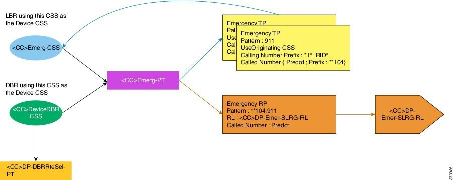
                                                    Figure 1. Emergency Calling

                                                    Configure SIP Trunks

                                                    Procedure
                                                      Step 1   Log in as the Provider, Reseller, or Customer Administrator.
                                                      Step 2   Make sure the hierarchy path is set to the node where the Cisco Unified Communications Manager is configured.
                                                      Step 3   Perform one of
                                                      • If you logged in as the Provider or Reseller Administrator, select Device Management > CUCM > SIP Trunks.
                                                      • If you logged in as the Customer Administrator, select Device Management > Advanced > SIP Trunks.
                                                      Step 4   Perform one of
                                                      • To add a new SIP trunk, click Add, then go to Step 4.
                                                      • To edit an existing SIP trunk, choose the SIP trunk to be updated by clicking on its box in the leftmost column, then click Modify to edit the selected SIP trunk. Go to Step 5.
                                                      Step 5   From the CUCM pulldown menu, select the hostname, domain name, or IP address of the Cisco Unified Communications Manager to which you want to add the SIP trunk.

                                                      Note   

                                                      The CUCM pulldown menu only appears when a SIP trunk is added; it does not appear when you edit a SIP trunk.

                                                      Important:

                                                      The only Cisco Unified Communications Managers that appear in the CUCM pulldown list are Cisco Unified Communications Managers that are located at the node where you are adding the SIP trunk, and all Cisco Unified Communications Managers in hierarchies above the node where you are adding the SIP trunk. To provision a Cisco Unified Communications Manager server, refer to the “Installation Tasks” section of Installing Cisco Unified Communications Manager.

                                                      Step 6   Enter a unique name for the new SIP trunk in the Device Name field, or modify the existing Device Name if desired.
                                                      Step 7   From the Device Information tab, modify the following fields as required.
                                                      Option Description
                                                      Device Name

                                                      (Mandatory)

                                                      Enter a unique identifier for the trunk using up to 50 alphanumeric characters: A-Z, a-z, numbers, hyphens (-) and underscores (_) only.

                                                      Default value: None

                                                      Trunk Service Type

                                                      (Mandatory)

                                                      Select one of
                                                      • None—Choose this option if the trunk is not used for call control discovery, Extension Mobility Cross Cluster, or Cisco Intercompany Media Engine
                                                      • Call Control Discovery—Choose this option to enable the trunk to support call control discovery.

                                                      • Extension Mobility Cross Cluster—Choose this option to enable the trunk to support the Extension Mobility Cross Cluster (EMCC) feature. Choosing this option causes the following settings to remain blank or unchecked and become unavailable for configuration, thus retaining their default values: Media Termination Point Required, Unattended Port, Destination Address, Destination Address IPv6, and Destination Address is an SRV.

                                                      • Intercompany Media Engine—Ensure that the Cisco IME server is installed and available before you configure this field.

                                                      • IP Multimedia Subsystem Service Control (ISC)—Choose this option to enable the trunk to support IP multimedia subsystem service control.

                                                      Default value: None (Default)

                                                      Description (Optional)

                                                      Enter a descriptive name for the trunk using up to 114 characters in any language, but not including double-quotes ("), percentage sign (%), ampersand (&), backslash (\), or angle brackets (<>).

                                                      Default value: empty

                                                      Device Pool

                                                      Choose the appropriate device pool for the trunk. For trunks, device pools specify a list of Cisco Unified Communications Managers that the trunk uses to distribute the call load dynamically.

                                                      Note   

                                                      Calls that are initiated from a phone that is registered to a Cisco Unified Communications Manager that does not belong to the device pool of the trunk use different Cisco Unified Communications Managers of this device pool for different outgoing calls. Selection of Cisco Unified Communications Manager nodes occurs in a random order. A call that is initiated from a phone that is registered to a Cisco Unified Communications Manager that does belong to the device pool of the trunk uses the same Cisco Unified Communications Manager node for outgoing calls if the Cisco Unified Communications Manager is up and running.

                                                      Default value: Default

                                                      Common Device Configuration

                                                      (Optional)

                                                      Choose the common device configuration to which you want this trunk assigned. The common device configuration includes the attributes (services or features) that are associated with a particular user.

                                                      Default value: None

                                                      Call Classification

                                                      (Mandatory)

                                                      This parameter determines whether an incoming call through this trunk is considered off the network (OffNet) or on the network (OnNet). When the Call Classification field is configured as Use System Default, the setting of the Cisco Unified Communications Manager clusterwide service parameter, Call Classification, determines whether the trunk is OnNet or OffNet. This field provides an OnNet or OffNet alerting tone when the call is OnNet or OffNet, respectively.

                                                      Default value: Use System Default

                                                      Media Resource Group List

                                                      (Optional)

                                                      This list provides a prioritized grouping of media resource groups. An application chooses the required media resource, such as a Music On Hold server, from among the available media resources according to the priority order that a Media Resource Group List defines.

                                                      Default value: None

                                                      Location

                                                      (Mandatory)

                                                      Use locations to implement call admission control (CAC) in a centralized call-processing system. CAC enables you to regulate audio quality and video availability by limiting the amount of bandwidth that is available for audio and video calls over links between locations. The location specifies the total bandwidth that is available for calls to and from this location.

                                                      Select the appropriate location for this trunk:
                                                      • Hub_None—Specifies that the locations feature does not keep track of the bandwidth that this trunk consumes.

                                                      • Phantom—Specifies a location that enables successful CAC across intercluster trunks that use H.323 protocol or SIP.

                                                      • Shadow—Specifies a location for intercluster enhanced location CAC. Valid for SIP intercluster trunks (ICT) only.

                                                      Default value: Hub_None

                                                      AAR Group

                                                      (Optional)

                                                      Choose the automated alternate routing (AAR) group for this device. The AAR group provides the prefix digits that are used to route calls that are otherwise blocked due to insufficient bandwidth. An AAR group setting of None specifies that no rerouting of blocked calls is attempted.

                                                      Default value: None

                                                      Tunneled Protocol Select the QSIG option if you want to use SIP trunks or SIP gateways to transport (tunnel) QSIG messages from Cisco Unified Communications Manager to other PINXs. QSIG tunneling supports the following features: Call Back, Call Completion, Call Diversion, Call Transfer, Identification Services, Path Replacement, and Message Waiting Indication (MWI).
                                                      Note    Remote-Party-ID (RPID) headers coming in from the SIP gateway can interfere with QSIG content and cause unexpected behavior with Call Back capabilities. To prevent interference with the QSIG content, turn off the RPID headers on the SIP gateway.

                                                      Default value: None

                                                      QSIG Variant

                                                      To display the options in the QSIG Variant drop-down list box, select QSIG from the Tunneled Protocol pulldown menu. This parameter specifies the protocol profile that is sent in outbound QSIG facility information elements.
                                                      From the pulldown menu, select one of
                                                      • No Changes—Default. Keep this parameter set to the default value unless a Cisco support engineer instructs otherwise.
                                                      • Not Selected

                                                      • ECMA—Select for ECMA PBX systems that use Protocol Profile 0x91

                                                      • ISO—Select for PBX systems that use Protocol Profile 0x9F

                                                      Default value: No Changes

                                                      ASN.1 ROSE OID Encoding

                                                      To display the options in the ASN.1 ROSE OID Encoding pulldown menu, choose QSIG from the Tunneled Protocol pulldown menu. This parameter specifies how to encode the Invoke Object ID (OID) for remote operations service element (ROSE) operations.
                                                      From the pulldown menu, select one of
                                                      • No Changes—Keep this parameter set to the default value unless a Cisco support engineer instructs otherwise.
                                                      • Not Selected

                                                      • Use Global Value ECMA—If you selected the ECMA option from the QSIG Variant pulldown menu, select this option.

                                                      • Use Global Value ISO—If you selected the ISO option from the QSIG Variant pulldown menu, select this option.

                                                      • Use Local Value

                                                      Default value: No Changes

                                                      Packet Capture Mode

                                                      This setting exists for troubleshooting encryption only; packet capturing may cause high CPU usage or call-processing interruptions.

                                                      From the pulldown menu, select one of
                                                      • None—This option, which serves as the default setting, indicates that no packet capturing is occurring. After you complete packet capturing, configure this setting.

                                                      • Batch Processing Mode—Cisco Unified Communications Manager writes the decrypted or nonencrypted messages to a file, and the system encrypts each file. On a daily basis, the system creates a new file with a new encryption key. Cisco Unified Communications Manager, which stores the file for seven days, also stores the keys that encrypt the file in a secure location. Cisco Unified Communications Manager stores the file in the PktCap virtual directory. A single file contains the time stamp, source IP address, source IP port, destination IP address, packet protocol, message length, and the message. The TAC debugging tool uses HTTPS, administrator username and password, and the specified day to request a single encrypted file that contains the captured packets. Likewise, the tool requests the key information to decrypt the encrypted file. Before you contact TAC, you must capture the SRTP packets by using a sniffer trace between the affected devices.

                                                      Default value: None

                                                      Packet Capture Duration

                                                      (Optional)

                                                      This setting exists for troubleshooting encryption only; packet capturing may cause high CPU usage or call-processing interruptions. This field specifies the maximum number of minutes that is allotted for one session of packet capturing.

                                                      To initiate packet capturing, enter a value other than 0 in the field. After packet capturing completes, the value, 0, displays.

                                                      Default value: 0 (zero), Range is from 0 to 300 minutes

                                                      Media Termination Point Required

                                                      (Optional)

                                                      You can configure Cisco Unified Communications Manager SIP trunks to always use an Media Termination Point (MTP). Check this box to provide media channel information in the outgoing INVITE request. When this check box is checked, all media channels must terminate and reoriginate on the MTP device. If you uncheck the check box, the Cisco Unified Communications Manager can decide whether calls are to go through the MTP device or be connected directly between the endpoints.

                                                      Note   

                                                      If the check box remains unchecked, Cisco Unified Communications Manager attempts to dynamically allocate an MTP if the DTMF methods for the call legs are not compatible. For example, existing phones that run SCCP support only out-of-band DTMF, and existing phones that run SIP support RFC2833. Because the DTMF methods are not identical, the Cisco Unified Communications Manager dynamically allocates an MTP. If, however, a new phone that runs SCCP, which supports RFC2833 and out-of band, calls an existing phone that runs SIP, Cisco Unified Communications Manager does not allocate an MTP because both phones support RFC2833. So, by having the same type of DTMF method supported on each phone, there is no need for MTP.

                                                      Default value: False (Unchecked)

                                                      Retry Video Call as Audio

                                                      (Optional)

                                                      This check box pertains to outgoing SIP trunk calls and does not impact incoming calls. By default, the system checks this check box to specify that this device should immediately retry a video call as an audio call (if it cannot connect as a video call) prior to sending the call to call control for rerouting. If you uncheck this check box, a video call that fails to connect as video does not try to establish as an audio call. The call then fails to call control, and call control routes the call using Automatic Alternate Routing (AAR) and route list or hunt list.

                                                      Default value: True (Checked)

                                                      Path Replacement Support

                                                      (Optional)

                                                      This check box is relevant when you select QSIG from the Tunneled Protocol pulldown menu. This setting works with QSIG tunneling to ensure that non-SIP information gets sent on the leg of the call that uses path replacement.

                                                      Default value: False (Unchecked)

                                                      Transmit UTF-8 for Calling Party Name

                                                      (Optional)

                                                      This device uses the user locale setting of the device pool to determine whether to send unicode and whether to translate received Unicode information. For the sending device, if you check this check box and the user locale setting in the device pool matches the terminating phone user locale, the device sends unicode. If the user locale settings do not match, the device sends ASCII. The receiving device translates incoming unicode characters based on the user locale setting of the sending device pool. If the user locale setting matches the terminating phone user locale, the phone displays the characters.

                                                      Note   

                                                      The phone may display malformed characters if the two ends of the trunk are configured with user locales that do not belong to the same language group.

                                                      Default value: False (Unchecked)

                                                      Transmit UTF-8 Names for QSIG APDU

                                                      (Optional)

                                                      This device uses the user locale setting of the device pool to determine whether to send unicode and whether to translate received Unicode information. For the sending device, if you check this check box and the user locale setting in the device pool matches the terminating phone user locale, the device sends unicode and encodes in UTF-8 format. If the user locale settings do not match, the device sends ASCII and encodes in UTF-8 format. If the configuration parameter is not set and the user locale setting in the device pool matches the terminating phone user locale, the device sends unicode (if the name uses 8 bit format) and encodes in ISO8859-1 format.

                                                      Default value: False (Unchecked)

                                                      Unattended Port

                                                      (Optional)

                                                      Check this check box if calls can be redirected and transferred to an unattended port, such as a voice mail port.

                                                      Default value: False (Unchecked)

                                                      SRTP Allowed

                                                      (Optional)

                                                      Check this check box if you want Cisco Unified Communications Manager to allow secure and nonsecure media calls over the trunk. Checking this check box enables Secure Real-Time Protocol (SRTP) SIP Trunk connections and also allows the SIP trunk to fall back to Real-Time Protocol (RTP) if the endpoints do not support SRTP. If you do not check this check box, Cisco Unified Communications Manager prevents SRTP negotiation with the trunk and uses RTP negotiation instead.

                                                      Caution   

                                                      If you check this check box, Cisco strongly recommends that you use an encrypted TLS profile, so that keys and other security related information do not get exposed during call negotiations. If you use a non-secure profile, SRTP still works but the keys get exposed in signaling and traces. In that case, you must ensure the security of the network between Cisco Unified Communications Manager and the destination side of the trunk.

                                                      Default value: False (Unchecked)

                                                      Consider Traffic on This Trunk Secure

                                                      This field provides an extension to the existing security configuration on the SIP trunk, which enables a SIP trunk call leg to be considered secure if SRTP is negotiated, independent of the signaling transport.

                                                      From the pulldown menu, select one of
                                                      • When using both sRTP and TLS

                                                      • When using sRTP Only—Displays when you check the SRTP Allowed check box

                                                      Default value: When using both sRTP and TLS

                                                      Route Class Signaling Enabled

                                                      From the pulldown menu, enable or disable route class signaling for the port. Route class signaling communicates special routing or termination requirements to receiving devices. It must be enabled for the port to support the Hotline feature.

                                                      From the pulldown menu, select one of
                                                      • Default—The device uses the setting from the Route Class Signaling service parameter

                                                      • Off—Enables route class signaling. This setting overrides the Route Class Signaling service parameter

                                                      • On—Disables route class signaling. This setting overrides the Route Class Signaling service parameter.

                                                      Default value: Default

                                                      Use Trusted Relay Point

                                                      (Mandatory)

                                                      From the pulldown menu, enable or disable whether Cisco Unified Communications Manager inserts a trusted relay point (TRP) device with this media endpoint. A Trusted Relay Point (TRP) device designates an MTP or transcoder device that is labeled as Trusted Relay Point. Cisco Unified Communications Manager places the TRP closest to the associated endpoint device if more than one resource is needed for the endpoint (for example, a transcoder or RSVPAgent). If both TRP and MTP are required for the endpoint, TRP gets used as the required MTP. If both TRP and RSVPAgent are needed for the endpoint, Cisco Unified Communications Manager first tries to find an RSVPAgent that can also be used as a TRP. If both TRP and transcoder are needed for the endpoint, Cisco Unified Communications Manager first tries to find a transcoder that is also designated as a TRP.

                                                      Select one of
                                                      • Default—The device uses the Use Trusted Relay Point setting from the common device configuration with which this device associates

                                                      • Off—Disables the use of a TRP with this device. This setting overrides the Use Trusted Relay Point setting in the common device configuration with which this device associates.

                                                      • On—Enables the use of a TRP with this device. This setting overrides the Use Trusted Relay Point setting in the common device configuration with which this device associates.

                                                      Default value: Default

                                                      PSTN Access

                                                      (Optional)

                                                      If you use the Cisco Intercompany Media Engine feature, check this check box to indicate that calls made through this trunk might reach the PSTN. Check this check box even if all calls through this trunk device do not reach the PSTN. For example, check this check box for tandem trunks or an H.323 gatekeeper routed trunk if calls might go to the PSTN. When checked, this check box causes the system to create upload voice call records (VCRs) to validate calls made through this trunk device.

                                                      Default value: True (Checked)

                                                      Run On All Active Unified CM Nodes

                                                      (Optional)

                                                      Check this check box to enable the trunk to run on every node.

                                                      Default value: False (Unchecked)

                                                      Step 8   From the Call Routing General tab, modify the following fields as required.
                                                      Option Description
                                                      Remote-Party-ID

                                                      (Optional)

                                                      Use this check box to allow or disallow the SIP trunk to send the Remote-Party-ID (RPID) header in outgoing SIP messages from Cisco Unified Communications Manager to the remote destination. If you check this box, the SIP trunk always sends the RPID header. If you do not check this box, the SIP trunk does not send the RPID header.

                                                      Note   

                                                      Be aware that Calling Name Presentation, Connected Line ID, and Connected Name Presentation are not available when QSIG tunneling is enabled.

                                                      Outgoing SIP Trunk Calls

                                                      The configured values of the Calling Line ID Presentation and Calling Name Presentation provide the basis for the construction of the Privacy field of the RPID header. Each of these two options can have the values of Default, Allowed, or Restricted. If either option is set to Default, the corresponding information (Calling Line ID Presentation and/or Calling Name Presentation) in the RPID header comes from the Call Control layer (which is based on call-by-call configuration) within Cisco Unified Communications Manager. If either option is set to Allowed or Restricted, the corresponding information in the RPID header comes from the SIP trunk configuration window.

                                                      Incoming SIP Trunk Calls

                                                      The configured values of the Connected Line ID Presentation and Connected Name Presentation provide the basis for the construction of the Privacy field of the RPID header. Each of these two options can have the values of Default, Allowed, or Restricted.

                                                      Be aware that the Connected Line ID Presentation and Connected Name Presentation options are relevant for 180/200 messages that the SIP trunk sends in response to INVITE messages that Cisco Unified Communications Manager receives. If either option is set to Default, the corresponding information (Connected Line ID Presentation and/or Connected Name Presentation) in the RPID header comes from the Call Control layer (which is based on call-by-call configuration) within Cisco Unified Communications Manager. If either option is set to Allowed or Restricted, the corresponding information in the RPID header comes from the SIP trunk configuration window.

                                                      Note   

                                                      The Remote-party ID and Asserted Identity options represent independent mechanisms for communication of display-identity information.

                                                      Default value: True (Checked)

                                                      Asserted-Identity

                                                      (Optional)

                                                      Use this check box to allow or disallow the SIP trunk to send the Asserted-Type and SIP Privacy headers in SIP messages. If you check this check box, the SIP trunk always sends the Asserted-Type header; whether or not the SIP trunk sends the SIP Privacy header depends on the SIP Privacy configuration.

                                                      Outgoing SIP Trunk Calls—P Headers

                                                      The decision of which Asserted Identity (either P-Asserted Identity or P-Preferred-Identity) header gets sent depends on the configured value of the Asserted-Type option. A non-default value for Asserted-Type overrides values that come from Cisco Unified Communications Manager Call Control. If the Asserted-Type option is set to Default, the value of Screening Identification that the SIP trunk receives from Cisco Unified Communications Manager Call Control dictates the type of Asserted-Identity.

                                                      Outgoing SIP Trunk Calls—SIP Privacy Header

                                                      The SIP Privacy header gets used only when you check the Asserted Identity check box and when the SIP trunk sends either a Privacy-Asserted Identity (PAI) or Privacy Preferred Identity (PPI) header. (Otherwise the SIP Privacy header neither gets sent nor processed in incoming SIP messages). The value of the SIP Privacy headers depends on the configured value of the SIP Privacy option. A non-default value for SIP Privacy overrides values that come from Cisco Unified Communications Manager Call Control.

                                                      If the SIP Privacy option is set to Default, the Calling Line ID Presentation and Calling Name Presentation that the SIP trunk receives from Cisco Unified Communications Manager Call Control determines the SIP Privacy header.

                                                      Incoming SIP Trunk Calls—P Headers

                                                      The decision of which Asserted Identity (either P-Asserted Identity or P-Preferred-Identity) header gets sent depends on the configured value of the Asserted-Type option. A non-default value for Asserted-Type overrides values that come from Cisco Unified Communications Manager Call Control. If the Asserted-Type option is set to Default, the value of Screening Identification that the SIP trunk receives from Cisco Unified Communications Manager Call Control dictates the type of Asserted-Identity.

                                                      Incoming SIP Trunk Calls—SIP Privacy Header

                                                      The SIP Privacy header gets used only when you check the Asserted Identity check box and when the SIP trunk sends either a PAI or PPI header. (Otherwise the SIP Privacy header neither gets sent nor processed in incoming SIP messages.) The value of the SIP Privacy headers depends on the configured value of the SIP Privacy option. A non-default value for SIP Privacy overrides values that come from Cisco Unified Communications Manager Call Control.

                                                      If the SIP Privacy option is set to Default, the Connected Line ID Presentation and Connected Name Presentation that the SIP trunk receives from Cisco Unified Communications Manager Call Control determine the SIP Privacy header.

                                                      Note   

                                                      The Remote-party ID and Asserted Identity options represent independent mechanisms for communication of display-identity information.

                                                      Default value: True (Checked)

                                                      Asserted-Type

                                                      From the pulldown menu, select one of the following values to specify the type of Asserted Identity header that SIP trunk messages should include:

                                                      • Default—Screening information that the SIP trunk receives from Cisco Unified Communications Manager Call Control determines the type of header that the SIP trunk sends.

                                                      • PAI—The Privacy-Asserted Identity header gets sent in outgoing SIP trunk messages; this value overrides the Screening indication value that comes from Cisco Unified Communications Manager.

                                                      • PPI—The Privacy Preferred Identity header gets sent in outoing SIP trunk messages; this value overrides the Screening indication value that comes from Cisco Unified Communications Manager.

                                                      Note   

                                                      These headers get sent only if the Asserted Identity check box is checked.

                                                      Default value: Default

                                                      SIP Privacy

                                                      (Mandatory)

                                                      From the pulldown menu, select one of the following values to specify the type of SIP privacy header for SIP trunk messages to include:

                                                      • Default—This option represents the default value; Name/Number Presentation values that the SIP trunk receives from the Cisco Unified Communications Manager Call Control compose the SIP Privacy header. For example, if Name/Number presentation specifies Restricted, the SIP trunk sends the SIP Privacy header; however, if Name/Number presentation specifies Allowed, the SIP trunk does not send the Privacy header.

                                                      • None—The SIP trunk includes the Privacy:none header and implies Presentation allowed; this value overrides the Presentation information that comes from Cisco Unified Communications Manager.

                                                      • ID—The SIP trunk includes the Privacy:id header and implies Presentation restricted for both name and number; this value overrides the Presentation information that comes from Cisco Unified Communications Manager.

                                                      • ID Critical—The SIP trunk includes the Privacy:id;critical header and implies Presentation restricted for both name and number. The label critical implies that privacy services that are requested for this message are critical, and, if the network cannot provide these privacy services, this request should get rejected. This value overrides the Presentation information that comes from Cisco Unified Communications Manager.

                                                      Note   

                                                      These headers get sent only if the Asserted Identity check box is checked.

                                                      Default value: Default

                                                      Step 9   From the Call Routing Inbound tab, modify the following fields as required.
                                                      Option Description
                                                      Significant Digits

                                                      (Mandatory)

                                                      Significant digits represent the number of final digits that are retained on inbound calls. Use for the processing of incoming calls and to indicate the number of digits that are used to route calls that are coming in to the SIP device.

                                                      Choose the number of significant digits to collect, from 0 to 32, or choose 99 to indicate all digits.

                                                      Note   

                                                      Cisco Unified Communications Manager counts significant digits from the right (last digit) of the number that is called.

                                                      Default value: 99

                                                      Connected Line ID Presentation

                                                      (Mandatory)

                                                      Cisco Unified Communications Manager uses connected line ID presentation (COLP) as a supplementary service to provide the calling party with the connected party number. The SIP trunk level configuration takes precedence over the call-by-call configuration.

                                                      Select one of
                                                      • Default—Allowed. Choose Default if you want Cisco Unified Communications Manager to send connected line information. If a call that originates from an IP phone on Cisco Unified Communications Manager encounters a device, such as a trunk, gateway, or route pattern, that has the Connected Line ID Presentation set to Default, the presentation value is automatically set to Allowed.

                                                      • Restricted—Choose Restricted if you do not want Cisco Unified Communications Manager to send connected line information.

                                                      Note   

                                                      Be aware that this service is not available when QSIG tunneling is enabled.

                                                      Default value: Default

                                                      Connected Name Presentation

                                                      (Mandatory)

                                                      Cisco Unified Communications Manager uses connected name ID presentation (CONP) as a supplementary service to provide the calling party with the connected party name. The SIP trunk level configuration takes precedence over the call-by-call configuration.

                                                      Select one of
                                                      • Default—Allowed. Choose Default if you want Cisco Unified Communications Manager to send connected name information.

                                                      • Restricted—Choose Restricted if you do not want Cisco Unified Communications Manager to send connected name information.

                                                      Note   

                                                      Be aware that this service is not available when QSIG tunneling is enabled.

                                                      Default value: Default

                                                      Calling Search Space

                                                      (Optional)

                                                      From the pulldown menu, choose the appropriate calling search space for the trunk. The calling search space specifies the collection of route partitions that are searched to determine how to route a collected (originating) number.

                                                      You can configure the number of items that display in this pulldown menu by using the Max List Box Items enterprise parameter. If more calling search spaces exist than the Max List Box Items enterprise parameter specifies, the Find button displays next to the drop-down list box. Click the Find button to display the Find and List Calling Search Spaces window. Find and choose a calling search space name.

                                                      Note   

                                                      To set the maximum list box items, choose System > Enterprise Parameters and choose CCMAdmin Parameters.

                                                      Default value: None

                                                      AAR Calling Search Space

                                                      (Optional)

                                                      Choose the appropriate calling search space for the device to use when performing automated alternate routing (AAR). The AAR calling search space specifies the collection of route partitions that are searched to determine how to route a collected (originating) number that is otherwise blocked due to insufficient bandwidth.

                                                      Default value: None

                                                      Prefix DN

                                                      (Optional)

                                                      Enter the prefix digits that are appended to the called party number on incoming calls. Cisco Unified Communications Manager adds prefix digits after first truncating the number in accordance with the Significant Digits setting. You can enter the international escape character +.

                                                      Default value: None

                                                      Redirecting Diversion Header - Delivery Inbound

                                                      (Optional)

                                                      Check this check box to accept the Redirecting Number in the incoming INVITE message to the Cisco Unified Communications Manager.

                                                      Uncheck the check box to exclude the Redirecting Number in the incoming INVITE message to the Cisco Unified Communications Manager.

                                                      You use Redirecting Number for voice messaging integration only. If your configured voice-messaging system supports Redirecting Number, you should check the check box.

                                                      Default value: False (Unchecked)

                                                      Incoming Calling Party - Prefix

                                                      (Optional)

                                                      Cisco Unified Communications Manager applies the prefix that you enter in this field to calling party numbers that use Unknown for the Calling Party Numbering Type. You can enter up to 8 characters, which include digits, the international escape field, you cannot configure the Strip Digits field. In this case, Cisco Unified Communications Manager takes the configuration for the Prefix and Strip Digits fields from the device pool that is applied to the device. If the word, Default, displays in the Prefix field in the Device Pool Configuration window, Cisco Unified Communications Manager applies the service parameter configuration for the incoming calling party prefix, which supports both the prefix and strip digit functionality.

                                                      Default value: None

                                                      Incoming Calling Party - Strip Digits

                                                      (Optional)

                                                      Enter the number of digits, up to the number 24, that you want Cisco Unified Communications Manager to strip from the calling party number of Unknown type before it applies the prefixes.

                                                      Default value: None

                                                      Incoming Calling Party - Calling Search Space

                                                      (Optional)

                                                      This setting allows you to globalize the calling party number of Unknown calling party number type on the device. Make sure that the calling party transformation CSS that you choose contains the calling party transformation pattern that you want to assign to this device. Before the call occurs, the device must apply the transformation by using digit analysis. If you configure the CSS as None, the transformation does not match and does not get applied. Ensure that you configure the calling party transformation pattern in a non-null partition that is not used for routing.

                                                      Default value: None

                                                      Incoming Calling Party - Use Device Pool CSS

                                                      (Optional)

                                                      Check this check box to use the calling search space for the Unknown Number field that is configured in the device pool that is applied to the device.

                                                      Default value: True (Checked)

                                                      Incoming Called Party - Prefix

                                                      (Optional)

                                                      Cisco Unified Communications Manager applies the prefix that you enter in this field to called numbers that use Unknown for the Called Party Number Type. You can enter up to 16 characters, which include digits, the international escape character (+), asterisk (*), or the pound sign (#). You can enter the word, Default, instead of entering a prefix.

                                                      Tip   

                                                      If the word, Default, displays in the Prefix field, you cannot configure the Strip Digits field. In this case, Cisco Unified Communications Manager takes the configuration for the Prefix and Strip Digits fields from the device pool that is applied to the device. If the word, Default, displays in the Prefix field in the Device Pool Configuration window, Cisco Unified Communications Manager does not apply any prefix or strip digit functionality.

                                                      Default value: None

                                                      Incoming Called Party - Strip Digits

                                                      (Optional)

                                                      Enter the number of digits that you want Cisco Unified Communications Manager to strip from the called party number of Unknown type before it applies the prefixes.

                                                      Tip   

                                                      To configure the Strip Digits field, you must leave the Prefix field blank or enter a valid configuration in the Prefix field. To configure the Strip Digits fields in these windows, do not enter the word, Default, in the Prefix field.

                                                      Default value: None

                                                      Incoming Called Party - Calling Search Space

                                                      (Optional)

                                                      This setting allows you to transform the called party number of Unknown called party number type on the device. If you choose None, no transformation occurs for the incoming called party number. Make sure that the calling search space that you choose contains the called party transformation pattern that you want to assign to this device.

                                                      Default value: None

                                                      Incoming Called Party - Use Device Pool CSS

                                                      (Optional)

                                                      Check this check box to use the calling search space for the Unknown Number field that is configured in the device pool that is applied to the device.

                                                      Default value: True (Checked)

                                                      Connected Party Transformation CSS

                                                      (Optional)

                                                      This setting is applicable only for inbound calls. This setting allows you to transform the connected party number on the device to display the connected number in another format, such as a DID or E164 number. Cisco Unified Communications Manager includes the transformed number in the headers of various SIP messages, including 200 OK and mid-call update and reinvite messages. Make sure that the Connected Party Transformation CSS that you choose contains the connected party transformation pattern that you want to assign to this device.

                                                      Note   

                                                      If you configure the Connected Party Transformation CSS as None, the transformation does not match and does not get applied. Ensure that you configure the Calling Party Transformation pattern used for Connected Party Transformation in a non-null partition that is not used for routing.

                                                      Default value: None

                                                      Use Device Pool Connected Party Transformation CSS

                                                      (Optional)

                                                      To use the Connected Party Transformation CSS that is configured in the device pool that is assigned to this device, check this check box. If you do not check this check box, the device uses the Connected Party Transformation CSS that you configured for this device in the Trunk Configuration window.

                                                      Default value: True (Checked)

                                                      Step 10   From the Call Routing Outbound tab, modify the following fields as required.
                                                      Option Description
                                                      Called Party Transformation CSS

                                                      (Optional)

                                                      This setting allows you to send the transformed called party number in an INVITE message for outgoing calls made over SIP Trunk. Make sure that the Called Party Transformation CSS that you choose contains the called party transformation pattern that you want to assign to this device.

                                                      Note   

                                                      If you configure the Called Party Transformation CSS as None, the transformation does not match and does not get applied. Ensure that you configure the Called Party Transformation CSS in a non-null partition that is not used for routing.

                                                      Default value: None

                                                      Use Device Pool Called Party Transformation CSS

                                                      (Optional)

                                                      To use the Called Party Transformation CSS that is configured in the device pool that is assigned to this device, check this check box. If you do not check this check box, the device uses the Called Party Transformation CSS that you configured for this device in the Trunk Configuration window.

                                                      Default value: True (Checked)

                                                      Calling Party Transformation CSS

                                                      (Optional)

                                                      This setting allows you to send the transformed calling party number in an INVITE message for outgoing calls made over a SIP Trunk. Also when redirection occurs for outbound calls, this CSS is used to transform the connected number that is sent from Cisco Unified Communications Manager side in outgoing reINVITE / UPDATE messages. Make sure that the Calling Party Transformation CSS that you choose contains the calling party transformation pattern that you want to assign to this device.

                                                      Tip   

                                                      If you configure the Calling Party Transformation CSS as None, the transformation does not match and does not get applied. Ensure that you configure the Calling Party Transformation Pattern in a non-null partition that is not used for routing.

                                                      Default value: None

                                                      Use Device Pool Calling Party Transformation CSS

                                                      (Optional)

                                                      To use the Calling Party Transformation CSS that is configured in the device pool that is assigned to this device, check this check box. If you do not check this check box, the device uses the Calling Party Transformation CSS that you configured in the Trunk Configuration window.

                                                      Default value: True (Checked)

                                                      Calling Party Selection

                                                      (Mandatory)

                                                      Choose the directory number that is sent on an outbound call. Select one of the following options to specify which directory number is sent:
                                                      • Originator—Send the directory number of the calling device

                                                      • First Redirect Number—Send the directory number of the redirecting device.

                                                      • Last Redirect Number—Send the directory number of the last device to redirect the call.

                                                      • First Redirect Number (External)—Send the external directory number of the redirecting device

                                                      • Last Redirect Number (External)—Send the external directory number of the last device to redirect the call.

                                                      Default value: Originator

                                                      Calling Line ID Presentation

                                                      (Mandatory)

                                                      Cisco Unified Communications Manager uses calling line ID presentation (CLIP) as a supplementary service to provide the calling party number. The SIP trunk level configuration takes precedence over the call-by-call configuration.

                                                      Select one of
                                                      • Default—Allowed. Choose Default if you want Cisco Unified Communications Manager to send calling number information.

                                                      • Restricted—Choose Restricted if you do not want Cisco Unified Communications Manager to send the calling number information.

                                                      Default value: Default

                                                      Calling Name Presentation

                                                      (Mandatory)

                                                      Cisco Unified Communications Manager used calling name ID presentation (CNIP) as a supplementary service to provide the calling party name. The SIP trunk level configuration takes precedence over the call-by-call configuration.

                                                      Select one of
                                                      • Default—Allowed. Choose Default if you want Cisco Unified Communications Manager to send calling name information.

                                                      • Restricted—Choose Restricted if you do not want Cisco Unified Communications Manager to send the calling name information.

                                                      Note   

                                                      This service is not available when QSIG tunneling is enabled.

                                                      Default value: Default

                                                      Calling and Connected Party Info Format

                                                      (Mandatory)

                                                      This option allows you to configure whether Cisco Unified Communications Manager inserts a directory number, a directory URI, or a blended address that includes both the directory number and directory URI in the SIP identity headers for outgoing SIP messages.

                                                      From the pulldown menu, select one of:
                                                      • Deliver DN only in connected party—In outgoing SIP messages, Cisco Unified Communications Manager inserts the calling party’s directory number in the SIP contact header information.

                                                      • Deliver URI only in connected party, if available—In outgoing SIP messages, Cisco Unified Communications Manager inserts the sending party’s directory URI in the SIP contact header. If a directory URI is not available, Cisco Unified Communications Manager inserts the directory number instead.

                                                      • Deliver URI and DN in connected party, if available—In outgoing SIP messages, Cisco Unified Communications Manager inserts a blended address that includes the calling party's directory URI and directory number in the SIP contact headers. If a directory URI is not available, Cisco Unified Communications Manager includes the directory number only.

                                                      Note   

                                                      You should set this field to Deliver URI only in connected party or Deliver URI and DN in connected party only if you are setting up URI dialing between Cisco Unified Communications Manager systems of Release 9.0 or greater, or between a Cisco Unified Communications Manager system of Release 9. 0 or greater and a third party solution that supports URI dialing. Otherwise, you must set this field to Deliver DN only in connected party.

                                                      Default value: Deliver DN only in connected party

                                                      Redirecting Diversion Header Delivery - Outbound

                                                      (Optional)

                                                      Check this check box to include the Redirecting Number in the outgoing INVITE message from the Cisco Unified Communications Manager to indicate the original called party number and the redirecting reason of the call when the call is forwarded.

                                                      Uncheck the check box to exclude the first Redirecting Number and the redirecting reason from the outgoing INVITE message. Use Redirecting Number for voice-messaging integration only. If your configured voice messaging system supports Redirecting Number, check the check box.

                                                      Default value: False (Unchecked)

                                                      Caller Information Caller ID DN

                                                      (Optional)

                                                      Enter the pattern, from 0 to 24 digits that you want to use to format the Called ID on outbound calls from the trunk. For example, in North America:
                                                      • 555XXXX = Variable Caller ID, where X represents an extension number. The Central Office (CO) appends the number with the area code if you do not specify it.

                                                      • 5555000 = Fixed Caller ID. Use this form when you want the Corporate number to be sent instead of the exact extension from which the call is placed. The CO appends the number with the area code if you do not specify it.

                                                      You can also enter the international escape character +.

                                                      Default value: None

                                                      Caller Information - Caller Name

                                                      (Optional)

                                                      Enter a caller name to override the caller name that is received from the originating SIP Device.

                                                      Default value: None

                                                      Caller Information - Maintain Original Caller ID DN and Caller Name in Identity Headers

                                                      (Optional)

                                                      This check box is used to specify whether you will use the caller ID and caller name in the URI outgoing request. If you check this check box, the caller ID and caller name is used in the URI outgoing request. If you do not check this check box, the caller ID and caller name is not used in the URI outgoing request.

                                                      Default value: False (Unchecked)

                                                      Step 11   From the SP Info tab, modify the following fields to as required.
                                                      Option Description
                                                      Destination Address is an SRV

                                                      (Optional)

                                                      This field specifies that the configured Destination Address is an SRV record.

                                                      Default value: False (Unchecked)

                                                      Destination - Destination Address IPv4

                                                      (Mandatory)

                                                      The Destination Address IPv4 represents the remote SIP peer with which this trunk will communicate. The allowed values for this field are an IP address, a fully qualified domain name (FQDN), or DNS SRV record only if the Destination Address is an SRV field is checked.

                                                      Tip   

                                                      For SIP trunks that can support IPv6 or IPv6 and IPv4 (dual stack mode), configure the Destination Address IPv6 field in addition to the Destination Address field.

                                                      Note   

                                                      SIP trunks only accept incoming requests from the configured Destination Address and the specified incoming port that is specified in the SIP Trunk Security Profile that is associated with this trunk.

                                                      Note   

                                                      For configuring SIP trunks when you have multiple device pools in a cluster, you must configure a destination address that is a DNS SRV destination port. Enter the name of a DNS SRV port for the Destination Address and check the Destination Address is an SRV Destination Port check box.

                                                      If the remote end is a Cisco Unified Communications Manager cluster, DNS SRV represents the recommended choice for this field. The DNS SRV record should include all Cisco Unified Communications Managers within the cluster.

                                                      Default value: None

                                                      Destination - Destination Address IPv6

                                                      (Mandatory if Destination - Destination Address IPv4 field above is not completed)

                                                      The Destination IPv6 Address represents the remote SIP peer with which this trunk will communicate. You can enter one of the following values in this field:
                                                      • A fully qualified domain name (FQDN)

                                                      • A DNS SRV record, but only if the Destination Address is an SRV field is checked.

                                                      SIP trunks only accept incoming requests from the configured Destination IPv6 Address and the specified incoming port that is specified in the SIP Trunk Security Profile that is associated with this trunk.

                                                      If the remote end is a Cisco Unified Communications Manager cluster, consider entering the DNS SRV record in this field. The DNS SRV record should include all Cisco Unified Communications Managers within the cluster.

                                                      Tip   

                                                      For SIP trunks that run in dual-stack mode or that support an IP Addressing Mode of IPv6 Only, configure this field. If the SIP trunk runs in dual-stack mode, you must also configure the Destination Address field.

                                                      Default value: None. If IPv4 field above is completed, this field can be left blank.

                                                      Destination - Destination port

                                                      (Mandatory)

                                                      Choose the destination port. Ensure that the value that you enter specifies any port from 1024 to 65535, or 0.

                                                      Note   

                                                      You can now have the same port number that is specified for multiple trunks.

                                                      You do not need to enter a value if the destination address is a DNS SRV port. The default 5060 indicates the SIP port.

                                                      Default value: 5060

                                                      Sort Order

                                                      (Mandatory)

                                                      Indicate the order in which the prioritize multiple destinations. A lower sort order indicates higher priority. This field requires an integer value.

                                                      Default value: Empty

                                                      MTP Preferred Originating Codec

                                                      (Mandatory)

                                                      Indicate the preferred outgoing codec by selecting one of:
                                                      • 711ulaw

                                                      • 711alaw

                                                      • G729/G729a

                                                      • G729b/G729ab

                                                      Note   

                                                      To configure G.729 codecs for use with a SIP trunk, you must use a hardware MTP or transcoder that supports the G.729 codec.

                                                      This field is used only when the MTP Termination Point Required check box is checked.

                                                      Default value: 711ulaw

                                                      BLF Presence Group

                                                      (Mandatory)

                                                      Configure this field with the Presence feature. From the pulldown menu, select a Presence group for the SIP trunk. The selected group specifies the destinations that the device/application/server that is connected to the SIP trunk can monitor.
                                                      • Standard Presence group is configured with installation. Presence groups that are configured in Cisco Unified Communications Manager Administration also appear in the pulldown menu.

                                                      • Presence authorization works with presence groups to allow or block presence requests between groups.

                                                      Tip   

                                                      You can apply a presence group to the SIP trunk or to the application that is connected to the SIP trunk. If a presence group is configured for both a SIP trunk and SIP trunk application, the presence group that is applied to the application overrides the presence group that is applied to the trunk.

                                                      Default value: Standard Presence Group

                                                      SIP Trunk Security Profile

                                                      (Mandatory)

                                                      Select the security profile to apply to the SIP trunk.

                                                      You must apply a security profile to all SIP trunks that are configured in Cisco Unified Communications Manager Administration. Installing Cisco Unified Communications Manager provides a predefined, nonsecure SIP trunk security profile for autoregistration. To enable security features for a SIP trunk, configure a new security profile and apply it to the SIP trunk. If the trunk does not support security, choose a nonsecure profile.

                                                      Default value: Non Secure SIP Trunk Profile

                                                      Rerouting Calling Search Space

                                                      (Optional)

                                                      Calling search spaces determine the partitions that calling devices can search when they attempt to complete a call. The rerouting calling search space gets used to determine where a SIP user (A) can refer another user (B) to a third party (C). After the refer is completed, B and C connect. In this case, the rerouting calling search space that is used is that of the initial SIP user (A).

                                                      Calling Search Space also applies to 3xx redirection and INVITE with Replaces features.

                                                      Default value: None

                                                      Out-Of-Dialog Refer Calling Search Space

                                                      (Optional)

                                                      Calling search spaces determine the partitions that calling devices can search when they attempt to complete a call. The out-of-dialog calling search space gets used when a Cisco Unified Communications Manager refers a call (B) that is coming into SIP user (A) to a third party (C) when no involvement of SIP user (A) exists. In this case, the system uses the out-of dialog calling search space of SIP user (A).

                                                      Default value: None

                                                      SUBSCRIBE Calling Search Space

                                                      (Optional)

                                                      Supported with the Presence feature, the SUBSCRIBE calling search space determines how Cisco Unified Communications Manager routes presence requests from the device/server/application that connects to the SIP trunk. This setting allows you to apply a calling search space separate from the call-processing search space for presence (SUBSCRIBE) requests for the SIP trunk.

                                                      From the pulldown menu, choose the SUBSCRIBE calling search space to use for presence requests for the SIP trunk. All calling search spaces that you configure in Cisco Unified Communications Manager Administration display in the SUBSCRIBE Calling Search Space pulldown menu.

                                                      If you do not select a different calling search space for the SIP trunk from the pulldown menu, the SUBSCRIBE calling search space defaults to None.

                                                      To configure a SUBSCRIBE calling search space specifically for this purpose, configure a calling search space as you do all calling search spaces.

                                                      Default value: None

                                                      SIP Profile

                                                      (Mandatory)

                                                      From the drop-down list box, select the SIP profile that is to be used for this SIP trunk.

                                                      Default value: Standard SIP Profile

                                                      DTMF Signaling Method

                                                      (Mandatory)

                                                      Select one of
                                                      • No Preference—Cisco Unified Communications Manager picks the DTMF method to negotiate DTMF, so the call does not require an MTP. If Cisco Unified Communications Manager has no choice but to allocate an MTP (if the Media Termination Point Required check box is checked), SIP trunk negotiates DTMF to RFC2833.

                                                      • RFC 2833—Choose this configuration if the preferred DTMF method to be used across the trunk is RFC2833. Cisco Unified Communications Manager makes every effort to negotiate RFC2833, regardless of MTP usage. Out of band (OOB) provides the fallback method if the peer endpoint supports it.

                                                      • OOB and RFC 2833—Choose this configuration if both out of band and RFC2833 should be used for DTMF.

                                                      Note   

                                                      If the peer endpoint supports both out of band and RFC2833, Cisco Unified Communications Manager negotiates both out-of-band and RFC2833 DTMF methods. As a result, two DTMF events are sent for the same DTMF keypress (one out of band and the other, RFC2833).

                                                      Default value: No Preference

                                                      Normalization Script

                                                      (Optional)

                                                      From the pulldown menu, choose the script that you want to apply to this trunk.

                                                      To import another script, on Cisco Unified Communications Manager go to the SIP Normalization Script Configuration window (Device > Device Settings > SIP Normalization Script), and import a new script file.

                                                      Default value: None

                                                      Normalization Script - Enable Trace

                                                      (Optional)

                                                      Check this check box to enable tracing within the script or uncheck the check box to disable tracing. When checked, the trace.output API provided to the Lua scripter produces SDI trace.

                                                      Note   

                                                      Cisco recommends that you only enable tracing while debugging a script. Tracing impacts performance and should not be enabled under normal operating conditions.

                                                      Default value: False (Unchecked)

                                                      Script Parameters

                                                      (Optional)

                                                      Enter parameter names and values in the format Param1Name=Param1Value; Param2Name=Param2Value where Param1Name is the name of the first script parameter and Param1Value is the value of the first script parameter. Multiple parameters can be specified by putting semicolon after each name and value pair . Valid values include all characters except equal signs (=), semi-colons (;); and non-printable characters, such as tabs. You can enter a parameter name with no value.

                                                      Recording Information

                                                      (Optional)

                                                      Enter one of
                                                      • 0—None (default)

                                                      • 1— This trunk connects to a recording-enabled gateway

                                                      • 2— This trunk connects to other clusters with recording-enabled gateways

                                                      Step 12   From the GeoLocation tab, modify the following fields as required.
                                                      Option Description
                                                      Geolocation

                                                      (Optional)

                                                      From the drop-down list box, choose a geolocation.

                                                      You can choose the Unspecified geolocation, which designates that this device does not associate with a geolocation.

                                                      On Cisco Unified Communications Manager, you can also choose a geolocation that has been configured with the System > Geolocation Configuration menu option.

                                                      Default value: None

                                                      Geolocation Filter

                                                      (Optional)

                                                      From the pulldown menu, choose a geolocation filter.

                                                      If you leave the <None> setting, no geolocation filter gets applied for this device.

                                                      On Cisco Unified Communications Manager, you can also choose a geolocation filter that has been configured with the System > Geolocation Filter menu option.

                                                      Default value: None

                                                      Send Geolocation Information

                                                      (Optional)

                                                      Check this check box to send geolocation information for this device.

                                                      Default value: False (Unchecked)

                                                      Step 13   Perform one of
                                                      • To save a new SIP trunk, click Save.
                                                      • To save an updated SIP trunk, click Update.
                                                      The SIP trunk appears in the SIP trunk list. You can view the SIP trunk and its characteristics by logging in to the Cisco Unified Communications Manager where the SIP trunk was added, selecting Device > Trunk, and performing the Find operation. When you click on the name of the SIP trunk in the list, the trunk characteristics are displayed.
                                                      Note   

                                                      The SIP trunk is automatically reset on the Cisco Unified Communications Manager as soon as it is added. To reset the SIP trunk at any other time, perform Reset SIP Trunks.


                                                      Delete SIP Trunks

                                                      Procedure
                                                        Step 1   Log in as the Provider/Reseller or Customer Administrator.
                                                        Step 2   Perform one of
                                                        • If you logged in as the Provider/Reseller Administrator, select Device Management > CUCM > SIP Trunks.
                                                        • If you logged in as the Customer Administrator, select Device Management > Advanced > SIP Trunks.
                                                        Step 3   From the list of trunks, choose the SIP trunk to be deleted, by clicking on its box in the leftmost column.
                                                        Step 4   Click Delete to delete the SIP trunk.
                                                        Step 5   From the popup window, click Yes to confirm the deletion.

                                                        Clone SIP Trunks

                                                        Use this procedure to copy the characteristics of a SIP trunk to one or more SIP trunks. The cloned SIP(s) can be associated with the same Cisco Unified Communications Manager instance as the original SIP trunk, or can be associated with another Cisco Unified Communications Manager.


                                                        Note


                                                        If you are cloning SIP trunks from one Cisco Unified Communications Manager to another Cisco Unified Communications Manager, check that the cloned Cisco Unified Communications Manager values are accurate. A cloned Cisco Unified Communications Manager may have invalid values, such as calling search spaces or locations.


                                                        Procedure
                                                          Step 1   Log in as the Provider/Reseller or Customer Administrator.
                                                          Step 2   Perform one of
                                                          • If you logged in as the Provider or Reseller Administrator, select Device Management > CUCM > SIP Trunks.
                                                          • If you logged in as the Customer Administrator, select Device Management > Advanced > SIP Trunks.
                                                          Step 3   From the list of trunks, choose the SIP trunk to be cloned, by clicking on its box in the leftmost column.
                                                          Step 4   Click Action > Clone.
                                                          Step 5   (Optional) From the CUCM pulldown menu, select a different hostname, domain name, or IP address of the Cisco Unified Communications Manager to which you want to add the SIP trunk.

                                                          Important:

                                                          The only Cisco Unified Communications Managers that appear in the CUCM pulldown list are Cisco Unified Communications Managers that are located at the hierarchy node where you added the original SIP trunk, or all nodes above it in the hierarchy. To provision a Cisco Unified Communications Manager server, refer to the “Installation Tasks” section of Installing Cisco Unified Communications Manager.

                                                          Step 6   Enter a unique name for the new SIP trunk in the Device Name field.
                                                          Step 7   Modify fields in the Device Information, Call Routing General, Call Routing Inbound, Call Routing Outbound, SIP Info, or GeoLocation tabs as required. For more information on field options and defaults, see Configure SIP Trunks.
                                                          Step 8   Click Save to save the cloned SIP trunk. The SIP trunk appears in the SIP trunk list. You can verify the SIP trunk and its characteristics by logging in to the Cisco Unified Communications Manager where the SIP trunk was added, selecting Device > Trunk, and performing the Find operation. When you click on the name of the SIP trunk in the list, the trunk characteristics are displayed.
                                                          Step 9   Repeat Steps 3 to 8 to clone another SIP trunk if desired.

                                                          Reset SIP Trunks

                                                          Use this procedure to shut down a SIP trunk and bring it back into service. This procedure does not physically reset the hardware; it only reinitializes the configuration that is loaded by the Cisco Unified Communications Manager cluster. To restart a SIP trunk without shutting it down, use Restart SIP Trunks.

                                                          Procedure
                                                            Step 1   Log in as the Provider/Reseller or Customer Administrator.
                                                            Step 2   Perform one of
                                                            • If you logged in as the Provider or Reseller Administrator, select Device Management > CUCM > SIP Trunks.
                                                            • If you logged in as the Customer Administrator, select Device Management > Advanced > SIP Trunks.
                                                            Step 3   From the list of trunks, choose the SIP trunk to be reset, by clicking on its box in the leftmost column.
                                                            Step 4   Click Edit to open the SIP trunk information.
                                                            Step 5   Select Action > Reset.

                                                            Restart SIP Trunks

                                                            Use this procedure to restart a SIP trunk without shutting it down first. To shut down a SIP trunk prior to the reset, see Reset SIP Trunks.


                                                            Note


                                                            If the SIP trunk is not registered with Cisco Unified Communications Manager, you cannot restart it.


                                                            Note


                                                            Restarting a SIP trunk drops all active calls that are using the trunk.


                                                            Procedure
                                                              Step 1   Log in as the Provider/Reseller or Customer Administrator.
                                                              Step 2   Perform one of
                                                              • If you logged in as the Provider/Reseller Administrator, select Device Management > CUCM > SIP Trunks.
                                                              • If you logged in as the Customer Administrator, select Device Management > Advanced > SIP Trunks.
                                                              Step 3   From the list of trunks, choose the SIP trunk to be restarted, by clicking on its box in the leftmost column.
                                                              Step 4   Click Edit to open the SIP trunk information.
                                                              Step 5   Select Action > Restart.

                                                              Configure Route Groups

                                                              A route group allows you to designate the order in which gateways are selected. It allows you to prioritize a list of gateways and ports for outgoing trunk selection.

                                                              For example, if you use two long distance carriers, you could add a route group so that long distance calls to the less expensive carrier are given priority. Calls only route to the more expensive carrier if the first trunk is unavailable.

                                                              Use this procedure to add or modify route groups.


                                                              Note


                                                              Each gateway or gateway and port combination can only belong to one route group and can only be listed once within that route group. All gateways in a route group must have the same route pattern. The pattern is assigned to the route list containing the route group (not the route group itself).

                                                              Route groups are optional. If a proposed route group only contains one gateway or one gateway and port combination and that route group is not to be included in a route list, the route group is not needed.


                                                              Before You Begin

                                                              You must define one or more gateway or SIP trunks before you add a route group.

                                                              Procedure
                                                                Step 1   Log in as the Provider/Reseller or Customer administrator.
                                                                Step 2   Perform one of
                                                                • If you logged in as the Provider or Reseller Administrator, select Device Management > CUCM > Route Groups.
                                                                • If you logged in as the Customer Administrator, select Device Management > Advanced > Route Groups.
                                                                Step 3   Perform one of
                                                                • To add a new route group, click Add.
                                                                • To edit an existing route group, choose the group to be updated by clicking on its box in the leftmost column, then click Update to edit the selected route group.
                                                                Step 4   From the CUCM pulldown menu, select or modify the Cisco Unified Communications Manager that corresponds to the route group.
                                                                Step 5   Enter a unique name for the new route group in the Route Group Name field, or modify the existing Route Group Name if desired. The name can comprise up to 50 alphanumeric characters and can contain any combination of spaces, period(s), hyphens (-), and underscore characters (_). Ensure that each route group name is unique to the route plan.
                                                                Tip   

                                                                Use concise and descriptive names for the route group. The CompanynameLocationGroup format usually provides a sufficient level of detail and is short enough to enable you to quickly and easily identify a route group. For example, “CiscoDallasAA1” identifies a Cisco Access Analog route group for the Cisco office in Dallas.

                                                                Step 6   From the pulldown menu, select or modify the Distribution Algorithm options for the route group. Default value is Circular.
                                                                Option Description
                                                                Top Down

                                                                Select this option if you want Cisco Unified Communications Manager to distribute a call to idle or available members starting with the first idle or available member of a route group to the last idle or available member of a route group.

                                                                Note   

                                                                You need to select Top Down to prioritize the order of devices in Step 10.

                                                                Circular

                                                                Select this option if you want Cisco Unified Communications Manager to distribute a call to idle or available members starting from the (n+1)th member of a route group, where the nth member is the member to which the Cisco Unified Communications Manager most recently extended a call. If the nth member is the last member of a route group, Cisco Unified Communications Manager distributes a call starting from the top of the route group.

                                                                Step 7   Click + to open the Members box. Perform one or more of the following steps:
                                                                • To add a device to the route group, perform Step 8.
                                                                • To modify the priority of a device, go to Step 10.
                                                                • To remove a device from the route group, go to Step 11.
                                                                Step 8   To add a device to the route group, from the Device Name pulldown menu, choose the device where the route group is added.
                                                                Note   

                                                                When a SIP trunk or gateway is added, all ports on the device are selected.

                                                                Step 9   To add another device to the route group, click + at the top of the Members box, then repeat Steps 8 and 9 for each additional device.
                                                                Step 10   To change the priority of a device, move the device up or down in the list by clicking the arrows on the right side of the Members box. Using the Up arrow, move the device higher in the list to make it a higher priority in the route group, or using the Down arrow, move the device lower in the list to make it a lower priority in the route group.
                                                                Note    The Top Down distribution algorithm must be selected in Step 6 to prioritize the order of devices.
                                                                Step 11   To remove a device from the route group, select the device in the Members box and click the – on the right side of the Members box.
                                                                Note   

                                                                You must leave at least one device in the route group.

                                                                Step 12   To save a new or updated route group, click Save. The route group appears in the Route Group list.

                                                                Delete Route Groups

                                                                Procedure
                                                                  Step 1   Log in as the Provider/Reseller or Customer Administrator.
                                                                  Note    When deleting a route group, ensure that you select a valid site under your customer in the hierarchy node breadcrumb at the top of the view. If you attempt to delete a route group at any other node in the hierarchy, you will receive an error indicating that you must be at a site.
                                                                  Step 2   Perform one of
                                                                  • If you logged in as the Provider or Reseller Administrator, select Device Management > CUCM > Route Groups.
                                                                  • If you logged in as the Customer Administrator, select Device Management > Advanced > Route Groups.
                                                                  Step 3   From the list of trunks, choose the route group to be deleted, by clicking on its box in the leftmost column. The Route Group profile appears.
                                                                  Step 4   Click Delete to delete the Route Group.
                                                                  Step 5   From the popup window, click Yes to confirm the deletion.

                                                                  Configure Route Lists

                                                                  Route lists are made up of route groups and are associated with route patterns. A route list associates a set of route groups with a route pattern and determines the order in which those route groups are accessed. The order controls the progress of the search for available trunk devices for outgoing calls.

                                                                  A route list can contain only route groups. Each route list should have at least one route group. Each route group includes at least one device, such as a gateway, that is available. Based on device type, Cisco Unified Communications Manager can choose some, or all, ports as resources in each route group. Some devices, such as digital access, only allow you to choose all ports.

                                                                  You can add a route group to any number of route lists.

                                                                  Use the following procedure to add route lists or to add, remove or change the order of route groups in a route list.

                                                                  Before You Begin

                                                                  Configure route groups before performing this procedure.

                                                                  Procedure
                                                                    Step 1   Log in to as the Provider/Reseller or Customer administrator.
                                                                    Note    When configuring a route list as a Provider or Reseller, ensure that you select a valid customer or site under your customer in the hierarchy node breadcrumb at the top of the view.
                                                                    Step 2   Perform one of
                                                                    • If you logged in as the Provider or Reseller Administrator, select Device Management > CUCM > Route Lists.
                                                                    • If you logged in as the Customer Administrator, select Device Management > Advanced > Route Lists.
                                                                    Step 3   Perform one of
                                                                    • To add a new route list, click Add, then go to Step 4.
                                                                    • To edit an existing route list, choose the list to be updated by clicking on its box in the leftmost column, then click Edit to update the selected route list. Go to Step 5.
                                                                    Step 4   From the CUCM pulldown menu, select a Cisco Unified Communications Manager for the route list.
                                                                    Step 5   Enter a unique name for the new route list in the Name field, or modify the existing route list Name if desired. The name can comprise up to 50 alphanumeric characters and can contain any combination of spaces, period(s), hyphens (-), and underscore characters (_). Ensure that each route list name is unique to the route plan.
                                                                    Tip   

                                                                    Use concise and descriptive names for the route list. The CompanynameLocationCalltype format usually provides a sufficient level of detail and is short enough to enable you to quickly and easily identify a route list. For example, “CiscoDallasMetro” identifies a route list for toll-free, inter-local access transport area (LATA) calls from the Cisco office in Dallas.

                                                                    Step 6   Enter or modify the description for the route list in the Description field.
                                                                    Step 7   From the Call Manager Group Name pulldown menu, select a Cisco Unified Communications Manager Group. Default is the default field. You can choose from Default, None or select a group.
                                                                    Note    The route list registers with the first Cisco Unified Communications Manager in the group (which is the Primary Cisco Unified Communications Manager).
                                                                    Step 8   Perform one of
                                                                    • To enable this route list, ensure that the Route List Enabled check box is checked (Default for a new route list).
                                                                    • To disable this route list, uncheck the Route List Enabled check box. Calls in progress do not get affected, but this route list does not accept additional calls.
                                                                    Step 9   To enable the active route list to run on every node, check the Run On Every Node check box.
                                                                    Step 10   To add a route group to this route list, perform the following steps:
                                                                    1. Click + on the right side of the Route Group Items box.
                                                                    2. From the Route Group Name pulldown menu, select the route group.
                                                                    Step 11   To remove a route group from this route list, click on the right side of its row in the Member box.
                                                                    Step 12   To change the priority of a route group, move it up or down in the list by clicking the arrows on the right side of the Member box. Using the Up arrow, move the group higher in the list to make it a higher priority, or using the Down arrow, move the group lower in the list to make it a lower priority.
                                                                    Step 13   To save a new or updated route list, click Save.

                                                                    Associate Local Route Groups to a Device Pool

                                                                    Use this procedure to associate a local route group with an existing device pool for each site. This allows calls from a device that is tied to a device pool to go out on a specific route group based on the call type. You cannot use this procedure to add or delete device pools.

                                                                    For example, you can associate multiple local route groups such as Emergency Route Group, Primary Local Route Group (for site A), Secondary Local Route Group (for site A), Primary Local Route Group (for site B), and Secondary Local Route Group (for site B). The Local Route Group feature enables you to specify different route groups for each site (site A and site B) for the respective device pool. Also, you can define a separate call routing option for emergency calls when you associate the Emergency Route Group with a different route group. Hence you can easily define separate call routing options for emergency calls and PSTN calls.

                                                                    Procedure
                                                                      Step 1   Log in to as the Provider/Reseller or Customer administrator.
                                                                      Note    When associating a local route group, ensure that you select a valid site under your customer in the hierarchy node breadcrumb at the top of the view. If you attempt to associate a local route group at any other node in the hierarchy, a popup alerts you to select a site hierarchy node.
                                                                      Step 2   Perform one of the following:
                                                                      • If you logged in as the Provider or Reseller Administrator, select Device Management > CUCM > Device Pools.
                                                                      • If you logged in as the Customer Administrator, select Device Management > Advanced > Device Pools.
                                                                      Step 3   Click the device pool to be associated.
                                                                      Step 4   From the Cisco Unified CM Group pulldown menu, select a specific Cisco Unified Communications Manager group or leave the Cisco Unified CM Group as Default.
                                                                      Step 5   Click the Local Route Group Settings tab.
                                                                      Step 6   In the grid, from the Local Route Group pulldown menu, select the local route group.
                                                                      Step 7   In the grid, from the Route Group pulldown menu, select the route group or gateway.
                                                                      Step 8   To save the new local route association, click Save.

                                                                      Load Balancing

                                                                      Cisco Unified Communications Manager groups provide both call-processing redundancy and distributed call processing. You can distribute devices, device pools, and Cisco Unified Communications Managers among the groups to improve redundancy and load balancing in your system.

                                                                      A Cisco Unified Communications Manager Group specifies a prioritized list of up to three Cisco Unified Communications Managers. The first Cisco Unified Communications Manager in the list serves as the primary Cisco Unified Communications Manager for that group, and the other members of the group serve as secondary and tertiary (backup) Cisco Unified Communications Managers.

                                                                      Each device pool has one Cisco Unified Communications Manager Group that is assigned to it. For example, Group 1 points to Device Pool 1, Group 2 points to Device Pool 2, and Group 3 points to Device Pool 3. When a device registers, it attempts to connect to the primary (first) Cisco Unified Communications Manager in the group that is assigned to its device pool. If the primary Cisco Unified Communications Manager is not available, the device tries to connect to the next Cisco Unified Communications Manager that is listed in the group, and so on.

                                                                      Load balancing is a manual process on Cisco Unified Communications Manager requiring you to perform the following tasks:

                                                                      1. Add new, custom Cisco Unified Communications Manager groups and device pools.

                                                                      2. Synchronize the groups and device pools into Cisco Unified Communications Domain Manager.

                                                                      3. Select the appropriate group and device pool in the Subscriber or Phone configuration for the site. To create more than one configuration for a site, create at least two Cisco Unified Communication Manager groups, then associate a device pool to the appropriate Cisco Unified Communications Manager group.

                                                                      To determine if load balancing is required for your network, you can check the current device traffic load in Cisco Unified Communications Manager using the System > Device Pool menu path. When you click on the device configuration information for a specific device pool, the Device Pool Information field lists the number of members in the Device Pool. Compare different device pools to see if the members are evenly divided between pools.

                                                                      To perform load balancing, see Load Balancing Using Site Default Device Pool.

                                                                      Load Balancing Using Site Default Device Pool

                                                                      A default device pool is created for each site when the site dial plan is deployed for the Type 1 through 4 dial plan schema groups. This procedure uses the default site device pools, so you do not need to create any additional device pools directly on Cisco Unified Communications Manager. Perform this procedure to load balance using the default site device pool. In this procedure, the default device pool is updated to point to the appropriate Cisco Unified Communications Manager group.

                                                                      Note


                                                                      Using this configuration, redundancy is gained within a site while load balancing is gained across multiple sites. Since there is one device pool per site, all devices at a site home to the same sequence of Cisco Unified Communications Managers, providing failover redundancy. Devices in different sites home to different sequences of Cisco Unified Communications Managers, providing load balancing across the sites.


                                                                      Note


                                                                      The default site device pool is not created until the Type 1 to 4 site dial plan has been deployed which updates the Site Defaults to use the default device pool. If the site dial plan has not been deployed, you will not see a site default device pool in the form Cu<customerId>Si<siteId>-DevicePool. You can determine the default device pool for a site in Cisco Unified Communications Domain Manager 10.6(1) by selecting Site Management > Defaults.


                                                                      Procedure
                                                                        Step 1   Log in as the Provider, Reseller, or Customer administrator.
                                                                        Step 2   Select the site from the hierarchy node breadcrumb at the top of the view in Cisco Unified Communications Domain Manager 10.6(1).
                                                                        Step 3   Follow the steps outlined in Create a Site Dial Plan if you have not already done so; the Create a Site Dial Plan procedure creates the default site device pool instance.
                                                                        Step 4   Log in to Cisco Unified Communications Manager and create one or more Cisco Unified Communications Manager groups on Cisco Unified Communications Manager. See Cisco Unified Communications Manager Administration Guide.
                                                                        Step 5   From Cisco Unified Communications Domain Manager 10.6(1), perform a sync operation of the Cisco Unified Communications Manager using the Administration Tools > Data Sync menu path. This sync updates the Cisco Unified Communications Domain Manager 10.6(1) cache and makes the Cisco Unified Communications Manager groups that were added directly on Cisco Unified Communications Manager available to Cisco Unified Communications Domain Manager 10.6(1).
                                                                        Step 6   Perform Associate Cisco Unified Communications Manager Group to a Device Pool, select a Cisco Unified Communications Manager group other than the default group in the Call Manager Group drop-down list.
                                                                        Note   

                                                                        To verify that the phone or subscriber uses the device pool as expected, select a subscriber from the list of subscribers in Cisco Unified Communications Domain Manager 10.6(1) (Subscriber Management > Subscribers) and check the Device Pool Name setting under the Phones tab.


                                                                        Associate Cisco Unified Communications Manager Group to a Device Pool

                                                                        Use this procedure to associate a Cisco Unified Communications Manager group with an existing device pool for each site. This allows calls from a device that is tied to a device pool to go out on a specific Cisco Unified Communications Manager group based on the call type. You cannot use this procedure to add or delete device pools.

                                                                        Procedure
                                                                          Step 1   Log in as the Provider/Reseller or Customer administrator.
                                                                          Note    When associating a Cisco Unified Communications Manager group, ensure that you select a valid site under your customer in the hierarchy node breadcrumb at the top of the view. If you attempt to associate a Cisco Unified Communications Manager group at any other node in the hierarchy, a popup alerts you to select a site hierarchy node.
                                                                          Step 2   Perform one of the following:
                                                                          • If you logged in as the Provider or Reseller Administrator, select Device Management > CUCM > Device Pools.
                                                                          • If you logged in as the Customer Administrator, select Device Management > Advanced > Device Pools.
                                                                          Step 3   Click the device pool to be associated.
                                                                          Step 4   From the Unified CM Group pulldown menu, select a specific Cisco Unified Communications Manager group or leave the Cisco Unified Communications Manager Group as Default.
                                                                          Step 5   To save the new Cisco Unified Communications Manager group association, click Save.