ICE Media Path Optimization

ICE Media Path Optimization

From X12.5, we support Interactive Connectivity Establishment (ICE) Media Path Optimization. This feature optimizes the media path for MRA endpoints, letting MRA-registered endpoints pass media directly between the endpoints, thereby bypassing the WAN and the Expressway servers.

This feature uses the ICE protocol (RFC 5245). Background information about ICE is provided in the About ICE and TURN Services section of the Cisco Expressway Administrator Guide at https://www.cisco.com/c/en/us/support/unified-communications/expressway-series/products-maintenance-guides-list.html.

How ICE Works

Before Cisco Expressway X12.5, ICE is supported only with the Cisco Expressway-C B2BUA as one of the ICE endpoints. When B2BUA acts as an endpoint, ICE candidates are negotiated between the endpoints and B2BUA. Therefore, the media always traverses through Cisco Expressway-E and Cisco Expressway-C.

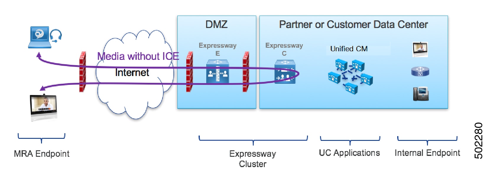
The following figure shows an MRA call that does not use ICE to optimize the media path. The media traverses through both the Cisco Expressway-E and the Cisco Expressway-C.

Figure 1. MRA Call Flow without ICE Media Path Optimization

With ICE Media Path Optimization, introduced in Cisco Expressway X12.5, each endpoint can pass the ICE candidates to the other endpoint through zones that traverse the SIP signaling. As a result, endpoints use the ICE protocol to negotiate the most optimal path for media. The most optimal path may be one of the following:

  • Host address—Represents the host IP address of the endpoint which is behind the NAT device.

  • Server-reflexive address—Represents the publicly accessible address of the endpoint on the NAT device.

  • Relay address—Represents the relay address of the endpoint configured on the TURN server.

In all ICE calls, initially media traverses through the Cisco Expressway-E and Cisco Expressway-C and then switches the media path depending on the negotiated ICE candidate type. This ensures that if endpoints are not ICE-capable, Cisco Expressway can use the legacy traversal path to pass media without disruption.

The following sections illustrate the MRA media path for each of the three ICE candidates.

MRA Call Flow with ICE using Host Address

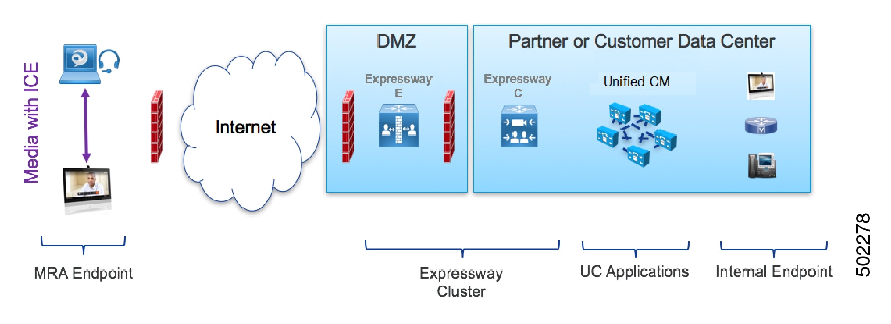
The following figure shows an MRA call with ICE where the Host address is used to establish the media path. The media directly passes between the endpoints using the Host address, because the endpoints reside in the same network with no firewall between them.

Figure 2. MRA Call Flow with ICE using Host Address

MRA Call Flow with ICE using Server Reflexive Addressing

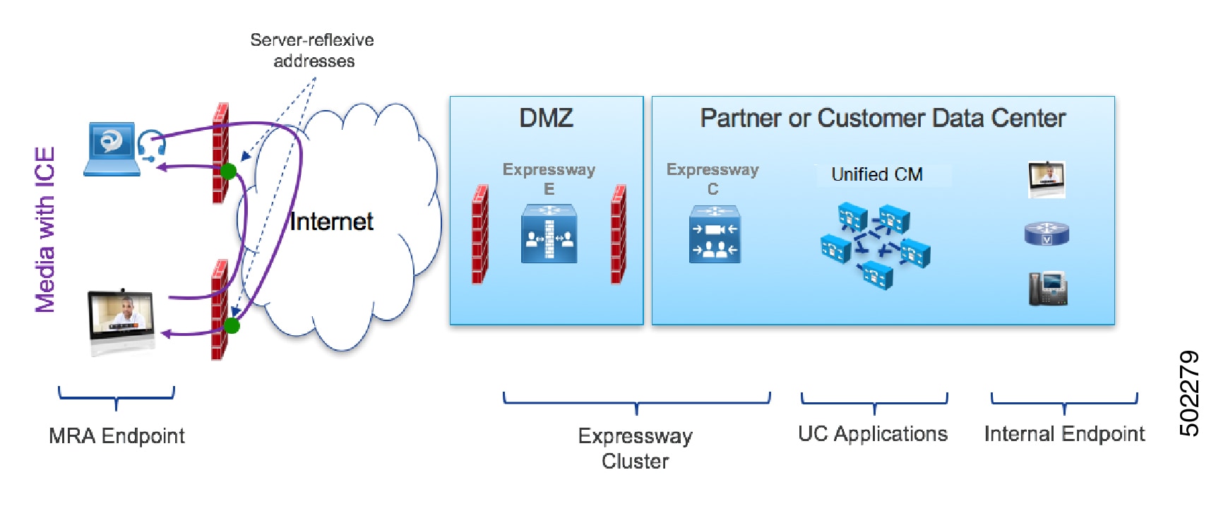
The following figure shows an MRA call with ICE where both endpoints are behind different firewalls, thereby preventing the Host address from being used. Instead, the media passes between the endpoints using Server-reflexive addressing because the endpoints are behind different firewalls.

Figure 3. MRA Call Flow with ICE using Server Reflexive Addressing

MRA Call Flow with ICE using Relay Address

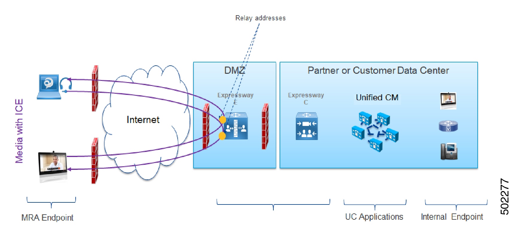
In cases where the Host and Server-reflexive addresses cannot negotiate successfully, like deployments with a symmetric NAT, endpoints can utilize TURN Relay as the ICE optimized media path. The following figure shows an MRA call with ICE where endpoints use the Relay address of the Cisco Expressway TURN server to send media between endpoints.

Figure 4. MRA Call Flow with ICE using Relay Address

Signaling Path Encryption Between Expressway-C and Unified CM

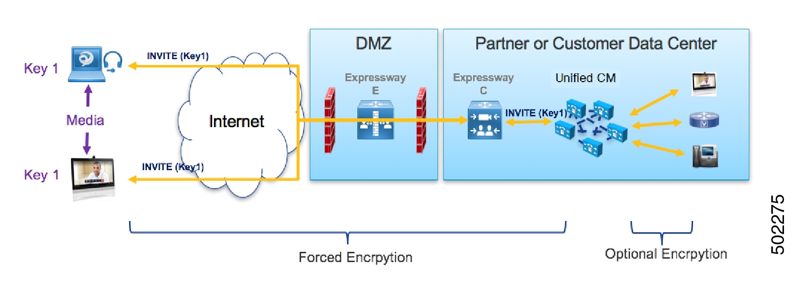
Security and encryption are important factors when considering direct endpoint-to-endpoint messaging. Because MRA endpoints are sending signaling and media over the internet, they are forced to operate in encrypted mode. In normal MRA mode (without ICE), encryption is always required between the endpoint and the Expressway-C but optional between the Expressway-C and Unified CM. This is possible because the Expressway-C can terminate the media stream and decrypt the packets if the internal leg is unencrypted.

The following figure shows the encryption without ICE Passthrough where encryption is forced between MRA endpoints and Expressway-C, and optional in the internal network. On an MRA call, a different encryption key is exchanged on each leg (Key 1 and Key 2), and the Expressway-C decrypts and re-encrypts the media between the 2 legs. The invite to Unified CM does not need a key if the internal leg is not encrypted.

Figure 5. Encryption without ICE Passthrough

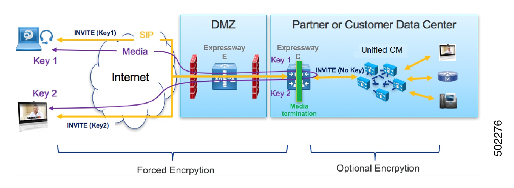
However, with ICE passthrough mode, the endpoints must be able to exchange their crypto keys end-to-end because the media packets are sent to each other directly and not through the Expressway-C. Whenever crypto keys are included in a SIP message, the message must be sent over TLS to protect the key. Because the SIP signaling path must be encrypted end-to-end to send the crypto keys end-to-end, the internal leg between the Expressway-C and Unified CM must be encrypted. If the signaling path is unencrypted, the crypto keys are dropped during call setup.

The following figure shows the encryption required with ICE Passthrough where the signaling leg between the Expressway-C and Unified CM is also encrypted.

Figure 6. Encryption with ICS Passthrough

Supported Components

Cisco Expressway-based Deployments

Currently, ICE Media Path Optimization support exists only on MRA deployments. It is not tested and supported on the following service deployments:

  • Cisco Webex Hybrid Services

  • Jabber Guest

  • Collaboration Meeting Room (CMR) Cloud

  • Business to Business Calling

HCS Deployments

ICE passthrough can be used to optimize the media path of the MRA calls in the following HCS deployment types:

  • HCS Shared Architecture

  • HCS Dedicated Server and HCS Dedicated Instance

  • Customer-owned Collaboration Architecture


Note


HCS Contact Center does not support ICE passthrough.

Supported Components

ICE Media Path Optimization is supported with the following components:

  • HCS 11.5 or later (for HCS deployments)

  • Cisco Unified Communications Manager (Unified CM) 11.5 or later

  • Cisco Expressway-C and Cisco Expressway-E X12.5 or later

Supported Endpoints

The following ICE-capable endpoints can send media directly to each other when they are MRA-registered and ICE Media Path Optimization is enabled:

  • Cisco Jabber clients, version 12.5 or later subject to using Unified Communications Manager 12.5 or later

  • Cisco IP Conference Phone 7832, version 12.5(1) or later

  • Cisco IP Phone 7800 Series (MRA-compatible models only), version 12.5(1) or later

  • Cisco IP Phone 8800 Series (MRA-compatible models only), version 12.5(1) or later

  • Cisco TelePresence DX, MX, SX Series, CE version 9.6.1 or later

Prerequisites for ICE Media Path Optimization

The following Cisco Unified Communications Manager prerequisites exist when deploying MRA endpoints with ICE Media Path Optimization:

Secure Mode Must be Running on Unified CM

It’s mandatory that one of the following secure modes be running on Cisco Unified Communications Manager:

  • SIP OAuth Mode is recommended for those endpoints that support it. SIP OAuth Mode is supported for:

    • Cisco Jabber or Webex clients on Unified CM Release 12.5(x) or later

    • Cisco IP Phone 7800 or 8800 series on Unified CM Release 14 or later

  • Mixed mode must be enabled if you are deploying SIP OAuth Mode over MRA with ICE and your endpoints do not support SIP OAuth Mode. This includes non-supported Cisco IP Phone or TelePresence devices. Mixed mode is also required for Cisco Jabber clients if you are not enabling SIP OAuth Mode, or if you are running a Unified CM release that is prior to 12.5(x).

    Mixed mode can be enabled by running the utils ctl set-cluster mixed-mode CLI command on the publisher node.

Phone Security Profile Must Include TLS Encryption

It’s mandatory that all MRA endpoints that use ICE Media Path Optimization be associated to a TLS-encrypted Phone Security Profile. Within the Phone Security Profile, the following settings must exist:

  • Device Security Mode is set to Encrypted

  • Transport Type is set to TLS

  • Enable OAuth Authentication is checked (if you are using SIP OAuth Mode) - CONFIRM

In addition, if mixed mode is enabled on Unified CM, the phone security profile name must be in the form of an FQDN.

Configuration

For details on how to configure SIP OAuth Mode, refer to the “SIP OAuth Mode” chapter of the Feature Configuration Guide for Cisco Unified Communications Manager.

For details on how to configure mixed mode and a TLS-encrypted phone security profile, see the Security Guide for Cisco Unified Communications Manager.

ICE Media Path Optimization Task Flow

Complete the following tasks to configure ICE Media Path Optimization for your MRA deployment.

Procedure

  Command or Action Purpose

Step 1

Configure ICE Settings

On Unified CM, configure ICE settings that you can apply to MRA endpoints.

Step 2

Install Server Certificates

On Expressway-C, install appropriate server certificates and trusted CA certificates.

Step 3

Change CEtcp Neighbor Zones to CEtls Neighbor Zones

On Expressway-C, change the existing CEtcp neighbor zone to a CEtls neighbor zone.

Step 4

Set Up the UC Traversal Zone for ICE Passthrough Support

On Expressway-C, set up the UC traversal zone for MRA.

Step 5

Set Up the UC Neighbor Zone for ICE Passthrough Support

On Expressway-C, set up the UC neighbor zone for MRA.

Step 6

Use CLI to Configure ICE Passthrough on Cisco Expressway Zones

On Expressway-C, configure ICE Media Path Optimization for the UC and CEtls neighbor zones.

Step 7

Set Up Cisco Expressway-E as TURN Server

On Expressway-E, configure TURN relay services.

Configure ICE Settings

On Cisco Unified Communications Manager, configure ICE settings within a Common Phone Profile, which you can apply to a group of MRA phones that use the profile.


Note


As an alternative to using a Common Phone Profile, ICE settings can be applied in any of the below Unified CM configuration windows as a part of the Product-Specific Configuration Layout. If conflicting configurations exist, the prioritized order below determines which configuration gets applied to the phone:

  1. Phone Configuration—Configure ICE settings on a phone-by-phone basis

  2. Common Phone Profile Configuration—Configure ICE settings to be applied to a group of phones that use the profile.

  3. Enterprise Phone Configuration—Configure ICE settings that are applied cluster-wide to phones that use those settings.

Regardless of which configuration window you use, by default ICE is Enabled with Host as the default candidate, and Server Reflexive addressing also being Enabled. However, to use Expressway-E relayed TURN services you must specify the Expressway-E server in the ICE settings of one of these windows.


Procedure


Step 1

From Cisco Unified CM Administration, choose Device > Device Settings > Common Phone Profile.

Step 2

Do either of the following:

  • Click Add New to create a new profile.
  • Click Find and select an existing profile. For example, the default Standard Common Phone Profile, which is assigned to new phones by default.

Step 3

Under Interactive Connectivity Establishment (ICE), configure the following ICE settings:

  • ICE—Make sure this is set to Enabled.
  • Default Candidate TypeHost is recommended.
  • Server Reflexive Address—Make sure this is set to Enabled
  • Primary TURN Server Host Name or IP Address—Enter the FQDN of an Expressway-E node to act as the primary TURN server.
  • Secondary TURN Server Host Name or IP Address—Enter the FQDN of an Expressway-E node to act as the secondary TURN server.
  • TURN Server Transport TypeAuto is recommended.
  • TURN Server Username—Enter a username that can access the Expressway-E server.
  • TURN Server Password—Enter the password for the user whom can access Expressway-E.

Step 4

Click Save.

Step 5

To apply the profile to a phone, do the following:

  1. Choose Device > Phone.

  2. Click Find and select the phone to which you want to apply the profile.

  3. Select the Common Phone Profile that you created.

  4. Click Save.


Install Server Certificates

This procedure describes how to install server certificates.

Procedure


Step 1

Generate a new CSR for the server certificate (Maintenance > Security > Server Certificate).

For more information, see the Cisco Expressway Certificate Creation and Use Deployment Guide on the Expressway configuration guides page.

Step 2

While generating the CSR, include the name of the phone security profile that you have associated with the endpoints in the Subject Alternate Names (SAN).

For more information, see CSR Requirements for Expressway Servers.

Step 3

Install the server certificate that is signed from the trusted certificate authority on Cisco Expressway-C.

This certificate allows the endpoints using the phone security profile to register over the TLS connection between Cisco Expressway-C and Unified CM.


Change CEtcp Neighbor Zones to CEtls Neighbor Zones

On Cisco Expressway-C, change the existing CEtcp neighbor zones that are already configured for MRA to CEtls neighbor zones.

Before you begin

Make sure that Unified CM is in a secure mode with one of the following modes being enabled:
  • Mixed Mode

  • SIP OAuth Mode

Procedure


Step 1

Go to Configuration > Unified Communications > Unified CM servers.

Step 2

Select the Unified CM Servers that you already discovered and click Refresh Servers to update the configuration.

Step 3

Verify that the Unified CM status shows TLS: Active.

If there is not already a CEtcp neighbor zone created, you may need to add your Unified CM servers and then refresh servers. Go to Add Unified CM Cluster.


Cisco Expressway-C automatically generates non-configurable CEtls neighbor zones between itself and each discovered Unified CM node if Unified CM cluster is in Secure mode. For more information, see Automatically Generated Zones and Search Rules.

Set Up the UC Traversal Zone for ICE Passthrough Support

This procedure describes how to set up the UC Traversal Zone for ICE passthrough support.

Procedure


Step 1

In Cisco Expressway-C, go to Configuration > Zones > Zones.

Step 2

Choose the Unified Communications traversal zone to Cisco Expressway-E.

Step 3

In the SIP pane, set ICE Passthrough support to On and ICE Support to Off.

Note


ICE Passthrough support takes precedence over ICE Support. Best practice is to turn on ICE Passthrough support and turn off ICE support.


Set Up the UC Neighbor Zone for ICE Passthrough Support

This procedure describes how to set up the UC Neighbor Zone for ICE passthrough support.

Procedure


Step 1

In Cisco Expressway-C, go to Configuration > Unified Communications > Unified CM Servers.

Step 2

Choose a server.

Step 3

In the Unified CM server lookup pane, set ICE Passthrough support to On.


Use CLI to Configure ICE Passthrough on Cisco Expressway Zones

The ICE Passthrough option in Cisco Expressway is a per-zone setup. You must enable ICE Passthrough on each Unified CM traversal client zone and CEtls neighbor zone.

You can use the CLI, instead of the web interface, to configure zones for ICE Passthrough.

Procedure


Step 1

Go to Configuration > Zones and click the Unified CM Traversal zone to Cisco Expressway-E.

Step 2

In the URL, note the ID of the zone. For example, in the following URL, 4 is the zone ID.

https://expressway.example.com/editzone?id=4

Step 3

Repeat steps 1 and 2 for the CEtls neighbor zone.

Step 4

Log in to the CLI of the Cisco Expressway-C as administrator.

Step 5

Run the following command to enable ICE Passthrough on Unified CM traversal client zone:

xConfiguration Zones Zone <Unified Communication Traversal client zone ID> TraversalClient SIP Media ICEPassThrough Support: On

Step 6

Run the following command to enable ICE Passthrough on the CEtls neighbor zone:

xConfiguration Zones Zone <CEtls Neighbor zone ID> Neighbor SIP Media ICEPassThrough Support: On

Set Up Cisco Expressway-E as TURN Server

You can use the Cisco Expressway-E server where the TURN server is running to allocate relay address and to retrieve the server reflexive address. This is typically a Cisco Expressway-E in the cluster used for MRA, but it is not required to be a Cisco Expressway-E server. You can use any compliant TURN server.

The following steps summarize the configuration required on the Cisco Expressway-E TURN server:

Procedure


Step 1

Configure the TURN server (Configuration > Traversal > TURN) with the following settings:

  • TURN services: Set to On.

  • TCP 443 TURN service: Set to Off.

  • TURN port multiplexing: Set to Off. This option is available only on Large system.

  • TURN requests port: Retain the default values. On Small and Medium systems, the default port is 3478. On Large systems, the default port range is 3478 to 3483.

    Note


    On a Large system, the TURN request port field is available only if TURN port multiplexing is set to On.

  • TURN requests port range start: Retain the default values.

  • TURN requests port range end: Retain the default values.

    Note


    The TURN requests port range start and TURN requests port range end options are available only on Large systems and if TURN port multiplexing is set to Off.

  • Delegated credential checking: Retain the default values.

  • Authentication realm: Retain the default value. The default value is TANDBERG.

  • Media port range start: Retain the default value. The default value is 24000.

  • Media port range end: Retain the default value. The default value is 29999.

Step 2

Configure the credentials (Configuration > Authentication > Devices > Local database) for TURN clients to authenticate with the TURN server.

Step 3

Click Save.

Step 4

Verify if the TURN server status is changed to Active under TURN server status.

For more information on the steps to configure TURN services on Cisco Expressway-E, see Configuring TURN Services section in the Cisco Expressway Administrator Guide at https://www.cisco.com/c/en/us/support/unified-communications/unified-communications-manager-callmanager/products-maintenance-guides-list.html.


ICE Passthrough Metrics Use

This section describes how to work with metrics for ICE passthrough in Cisco Expressway:

  • View ICE Passthrough Metrics in Cisco Expressway-C

  • Use the collectd Daemon to Gather Metrics

  • View Call Types in the Call History

  • Bandwidth Manipulation

View ICE Passthrough Metrics in Expressway-C

In Expressway-C, you can view metrics data for completed ICE passthrough calls. Various metrics are available for each server that is configured to route ICE passthrough calls. Values are updated once every 24 hours.

Figure 7. Metrics Example
  • The Peer field shows the IP address or hostname of each node.

  • The most recent 24-hour interval of data is shown.

  • Each peer address is a link that takes you to the history for that node.

  • The interval start time reflects the time of day of the most recent server restart.

  • Each column shows information for a separate cluster.

Procedure


Step 1

In Expressway-C, go to Status > ICE Passthrough metrics.

The page is organized into these sections:

  • Metrics: For each peer, the time interval for which metrics are shown. For this interval, the number of B2BUA connected calls, the number of ICE calls, and the percentage of ICE vs total B2BUA calls. N/A values result when no ICE calls were processed during this 24-hour interval.

  • Call types: For each call type, the percentage of placed ICE calls with each call type.

  • Advanced: Other metrics that can help with troubleshooting.

Step 2

For a detailed description of any field, click the i icon next to the field name.

Step 3

To sort, click a column name and then the Up or Down arrow, to sort the data by that column.

Step 4

Click Export to CSV to create a spreadsheet of the values on the page you are displaying.

Step 5

Click the IP address or hostname for a cluster to display the ICE Call Metrics History page, which shows a history of values for that cluster.

  • Each column shows a separate parameter.

  • Each row shows the values for a different interval, with the most recent shown first.

  • Each value is a raw value, not a percentage.

  • The page can display up to 60 records (that is, the 60 most recent 24-hour intervals).


Metric Collection with the collectd Daemon

As an alternative to viewing metrics for ICE passthrough calls, you can use the collectd daemon to gather the metrics. Details about setting up the server for collection are in the Cisco Expressway Serviceability Guide on the Expressway Maintain and Operate Guides page, in the "Introducing System Metrics Collection" section.

View Call Types in the Call History

For ICE passthrough calls, the call type is shown in the call history.

Procedure


Step 1

In Cisco Expressway-C, navigate to Status > Calls > History.

Step 2

Choose one of the following actions.

  • Click the value in the Start time column to view the call detail record (CDR).
  • Choose View in the Actions column.

Step 3

Examine the value in the ICE Passthrough call type field.

Possible values are:

  • none: Indicates optimized media path was not used for the call. The call is processed and connected using Cisco Expressway B2BUA.

  • host_to_host: Indicates optimized media path for the call was established using the host addresses of the endpoints.

  • host_to_srvrflx: Indicates optimized media path for the call was established between the host address of one of the endpoints and the server-reflexive address of the other endpoint.

  • host_to_relay: Indicates optimized media path for the call was established between the host address of one of the endpoints and the TURN relay address of the other endpoint.

  • srvrflx_to_srvrflx: Indicates optimized media path for the call was established using the server-reflexive addresses of the endpoints.

  • srvrflx_to_relay: Indicates optimized media path for the call was established between the server-reflexive address of one of the endpoints and the TURN relay address of the other endpoint.

  • relay_to_relay: Indicates optimized media path for the call was established using the relay addresses of the endpoints.

Step 4

(Optional) To view the details of the B2BUA call leg, choose the call leg that shows the B2BUA type in the Call components section.


Bandwidth Manipulation

When ICE is negotiated, media moves off the Cisco Expressway, which results in a reduction in media bandwidth. When the Status > Bandwidth > Links page displays current bandwidth, the total current usage reflects less utilization when ICE is in use.


Note


Bandwidth usage does not include the bandwidth that the TURN server uses.