Mobile Agent

Capabilities

Cisco Unified Mobile Agent Description

Unified Mobile Agent supports call center agents using phones that your contact center enterprise solution does not directly control. You can deploy a Mobile Agent as follows:

  • Outside the contact center, by using an analog phone or a mobile phone in the home.

  • On an IP phone connection that is not CTI-controlled by Packaged CCE or by an associated Unified Communications Manager.

  • On any voice endpoint of any ACD (including endpoints on other Unified Communication Managers) that the contact center Unified Communication Manager can reach by a SIP trunk.

A Mobile Agent can use different phone numbers at different times; the agent enters the phone number at login time. An agent can access the Mobile Agent functionality using any phone number that is included in the Unified Communications Manager dial plan.

Unified Mobile Agent Provides Agent Sign-In Flexibility

Agents can be either local agents or Mobile Agents, depending on how they sign in at various times.

Regardless of whether agents sign in as local or Mobile Agents, their skill groups do not change. Because agents are chosen by existing selection rules and not by how they are connected, the same routing applies regardless of how the agents log in. If you want to control routing depending on whether agents are local or mobile, assign the agents to different skill groups and design your scripts accordingly.

Connection Modes

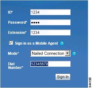
Cisco Unified Mobile Agent allows system administrators to configure agents to use either call by call dialing or a nailed connection, or the administrator can configure agents to choose a connection mode at login time.

Mobile Agents are defined as agents using phones not directly controlled by Unified CC, irrespective of their physical location. (The term local agent refers to an agent who uses a phone that is under control of Unified CC, irrespective of physical location.)

You can configure Mobile Agents using either of two delivery modes:

  • Call by Call—In this mode, the Mobile Agent's phone is dialed for each incoming call. When the call ends, the Mobile Agent's phone is disconnected before being made ready for the next call.

  • Nailed Connection—In this mode, the agent is called at login time and the line stays connected through multiple customer calls.


Note

The administrator can select the Agent chooses option, which allows an agent to select a call delivery mode at login.
Call by Call

In a call by call delivery mode, the Mobile Agent's phone is dialed for each incoming call. When the call ends, the Mobile Agent's phone disconnects before is it made ready for the next call.

The call by call call flow works as follows:

  1. At login, the agent specifies an assigned extension for a CTI port.

  2. A customer call arrives in the system and, through normal Unified ICM configuration and scripting, is queued for a skill group or an agent. (This is no different than existing processing for local agents.)

  3. The system assigns an agent to the call. If the agent's Desk Setting is Unified Mobile Agent-enabled and configured for either call by call or Agent chooses mode, the router uses the extension of the agent's CTI port as a label.

  4. The incoming call rings at the agent's CTI port. The JTAPI Gateway and PIM notice this but do not answer the call.

  5. A call to the agent is initiated on another CTI port chosen from a preconfigured pool. If this call fails, Redirect on No Answer processing is initiated.


    Note

    In call by call mode, the Answer Wait Time is 3 to 15 seconds longer than in a local agent inbound call scenario. Specify a Redirect on No Answer setting large enough to accommodate the extra processing time.
  6. When the agent takes the remote phone off-hook to answer the call, the system directs the customer call to the agent's call media address and the agent's call to the customer's call media address.

  7. When the call ends, both connections are terminated and the agent is ready to accept another call.


Note

To configure Mobile Agent in call by call delivery mode, you must set the wrap-up timer to at least one second using the Agent Desktop Settings List tool in the Configuration Manager.

In call by call delivery mode, callers often perceive a longer ring time compared to nailed connection delivery mode. This is because callers hear the ringtone during the call flow; ringing stops only after the agent answers. From the Unified CCE reporting perspective, a Mobile Agent in call by call delivery mode has a longer Answer Wait Time for the same reason.


Nailed Connections

In nailed connection delivery mode, the agent is called once, at login, and the phone line remains connected through multiple customer calls. See the following figure.

Figure 1. Nailed Connection Call Flow

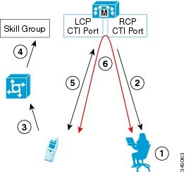
The nailed connection call flow works as follows:

  1. At login, the agent enters the directory number of the local CTI port (LCP) and the remote phone number in the Desktop.

    The remote phone number can be any phone number reachable by Unified CM.

    When the agent clicks the Login button, a call is initiated to the agent's remote CTI port (RCP) and the agent's remote phone rings.

  2. When the agent answers the call, the call is then nailed up. This means that the agent will remain on this call until the agent logs out or hangs up.

  3. A customer's call arrives in the system and, through normal Packaged CCE configuration and scripting, is queued for a skill group/precision queue. (This is no different than existing processing for local agents.)

  4. When the agent clicks the Answer button, the voice path between the agent and the customer phone is established, and the two parties can talk.

  5. When the system assigns an agent to the call, the call is routed to the agent's LCP port. The agent then hears the connect tone on the headset.

  6. When the call ends, the customer connection is terminated and the agent state returns to Ready.

Connect Tone

The Connect Tone feature in the nailed connection mode enables the system to play a tone to the Mobile Agent through the agent's headset to let the agent know when a new call is connected.

Connect Tone is particularly useful when Auto Answer is enabled or the agent is an Outbound agent. Here are its features:

  • An audible tone (two beeps) is sent to the Mobile Agent headset when the call to the nailed connection Mobile Agent is connected. It is a DTMF tone played by Unified CM and cannot be modified.

  • The Connect Tone plays only when the nailed connection Mobile Agent receives a call, as in the following examples:

    • The agent receives a consultation call.

    • The agent receives an outbound call.

  • The Connect Tone does not play when the Mobile Agent initiates a call, as in the following examples:

    • The agent makes a call.

    • The agent makes the consultation call.

    • Outbound direct preview call is made.

    • Supervisor barge-in call is made.

Agent Greeting and Whisper Announcement

The Agent Greeting and Whisper Announcement features are available to Unified Mobile Agents. The following sections explain more about how these features apply to Unified Mobile Agents.

Agent Greeting

You can use the Agent Greeting feature to record a message that plays automatically to callers when they connect to you. Your greeting message can welcome the caller, identify you, and include other useful information.

Limitations

The following limitations apply to the Agent Greeting feature for Mobile Agents.

  • A supervisor cannot barge in when an Agent Greeting is playing.

  • If a Peripheral Gateway (PG), JTAPI Gateway (JGW), or PIM failover occurs when an Agent Greeting plays for a Mobile Agent, the call fails.

  • If a Mobile Agent hangs up when an Agent Greeting plays, the customer still hears the complete Agent Greeting before the call ends.


    Note

    In the Agent Greeting Call Type Report, this call does not appear as a failed agent greeting call.


For more information about Agent Greeting, see Capabilities.

Whisper Announcement

With Whisper Announcement, agents can hear a brief prerecorded message just before they connect with each caller. The announcement plays only to the agent; the caller hears ringing (based on existing ringtone patterns) while the announcement plays. The announcement can contain information about the caller, such as language preference or customer status. This information helps the agent prepare for the call.

Configuration Requirement

For the Whisper Announcement feature for Unified Mobile Agents, you require a Media Termination Point (MTP) resource on an incoming SIP device.

Feature Requirements

Phone Requirements

A Unified Mobile Agent can use an analog, digital, or IP phone to handle calls.


Note

When Unified Mobile Agent phones are located on a cluster and a SIP Trunk is used to connect the cluster to another cluster under Packaged CCE control, you must either use SIP phones as Mobile Agent phones or select mtp required on the Packaged CCE cluster to allow Mobile Agent calls to work.

Conference Requirements

To use Agent Greeting for Mobile Agents, you must configure external conference-bridge (hardware) resources. To estimate the number of required resources, you can use the following formula:

Number of conference bridge resources = Mobile Agent call rate × Average greeting time (in seconds)

For information about configuring external conference-bridge resources, see the dspfarm profile 1 for conference configuration section in the sample configuration gateway, listed in Media Termination Points Configuration.

CTI Port Requirements

You need two CTI ports (local and remote) for every logged-in Mobile Agent.

Unified Mobile Agent uses Unified CM CTI Port as a proxy for the agent's phone. When this proxy is set up, whenever a Mobile Agent is selected to handle a customer call, the following happens:

  • The call is directed to the CTI port extension.

  • Packaged CCE intercepts the call arriving on the CTI Port and directs Unified CM to connect the call to the Mobile Agent.

For Unified Mobile Agent to work properly, you must configure two CTI ports:

  • One port to serve as the agent's virtual extension.

  • The other port to initiate calls to the agent.

You must assign these CTI ports to the Packaged CCE application. The ports are recognized by Packaged CCE when receiving the Unified CM configuration.

For these CTI ports in IPv6 enabled deployments, you have to set IP Addressing Mode to IPv4 Only. You do this by creating a Common Device Configuration and referencing it to these CTI ports.

Important Considerations

Before you proceed, consider the following Unified Mobile Agent limitations and considerations:

Failover

  • During a failover, if an agent in call by call mode answers an alerting call, the call can drop. This occurs because the media cannot be bridged when there is no active PG.

  • During a prolonged Peripheral Gateway (PG) failover, if an agent takes call control action for a Unified Mobile Agent-to-Unified Mobile Agent call, the call can drop. This occurs because the activating PG may not have information for all agents and calls at that point.

  • Unified Communications Manager failover causes a Mobile Agent call to be lost.

  • If a call by call Mobile Agent initiates a call (including a supervisor call) and does not answer the remote leg of the call before PG failover, the call fails. The agent must disconnect the remote agent call leg and reinitiate the call.

Performance

  • For the total number of supported Unified Mobile Agents and more information about Unified Mobile Agent capability, see Solution Design Guide for Cisco Packaged Contact Center Enterprise at https://www.cisco.com/c/en/us/support/customer-collaboration/packaged-contact-center-enterprise/products-technical-reference-list.html.

  • Because Unified Mobile Agent adds processing steps to Unified CCE default functionality, Mobile Agents may experience some delay in screen popup windows.

  • From a caller's perspective, the call by call delivery mode has a longer ring time compared with the nailed connection delivery mode. This is because Unified CCE does not start to dial the Mobile Agent's phone number until after the call information is routed to the agent desktop. In addition, the customer call media stream is not connected to the agent until after the agent answers the phone.

    The caller hears a repeated ringtone while Unified CCE makes these connections.

Codec

The codec settings on the Peripheral Gateway and Voice Gateway must match. Perform the following procedure:
  1. Launch the Peripheral Gateway Setup.

  2. In the Peripheral Gateway Component Properties, select the UCM PIM and click Edit.

  3. In the CallManager Parameters section, select the appropriate codec from the Mobile Agent Codec drop down list.

    Figure 2. Mobile Agent Codec Selection


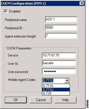
Unsupported Features

The following is a list of unsupported features for Mobile Agent:

  • Web Callback

  • Unified CM-based Silent Monitoring

  • Agent Request

Unified Mobile Agent Reporting

Unified Mobile Agent-specific call data is contained in the following Cisco Unified Intelligence Center reports: Agent Team Historical, Agent Real Time, and Agent Skill Group Historical. These “All Field” reports contain information in multiple fields that show what kind of call the agent is on (nonmobile, call by call, nailed connection) and the Unified Mobile Agent phone number.


Note

The service level for Unified Mobile Agent calls might be different than the service level for local agent calls, because it takes longer to connect the call to the agent.

For example, a call by call Mobile Agent might have a longer Answer Wait Time Average than a local agent. This is because Packaged CCE does not start to dial the Mobile Agent phone number until after the call information is routed to the agent desktop. In addition, the customer call media stream is not connected to the agent until after the agent answers the phone.


Initial Setup

Summary of Unified Mobile Agent System Configuration Tasks

The following table describes system configuration tasks for Unified Mobile Agent.

Table 1. Unified Mobile Agent System Configuration Tasks

Task

See

Configure Unified CM CTI Port pools

Unified CM CTI Port Configuration and Mapping for Unified Mobile Agent

Configure Unified CM Call Duration Timer

Maximum Call Duration Timer configuration

Configure Agent Desk Settings

Agent Desk Setting Configuration for Unified Mobile Agent

Configure Media Termination Points

Media Termination Points Configuration

Unified CM CTI Port Configuration and Mapping for Unified Mobile Agent

Unified Mobile Agent must have two CTI ports configured on Unified CM:

  • A local CTI port, which Unified Mobile Agent uses as the agent's virtual extension.

  • A remote CTI port, which Unified Mobile Agent uses to initiate a call to the Mobile Agent's phone.

Naming Conventions for Local and Network Ports

  • The local port must begin with the string LCP.

  • The remote port must begin with the string RCP.

  • The remaining characters in the device names for the LCP and RCP pair must match. For example an LCP port named LCP0000 has a corresponding RCP port named RCP0000.

Music on Hold Design

If you want callers to hear music when a Mobile Agent places the caller on hold, you must assign Music on Hold (MoH) resources to the ingress voice gateway or trunk that is connected to the caller (as you do with traditional agents). In this case, the user or network audio source is specified on the local CTI port configuration. Similarly, if a Mobile Agent must hear music when the system puts the agent on hold, you must assign MoH resources to the ingress voice gateway or trunk that is connected to the Mobile Agent. In this case, the user or network audio source is specified on the remote CTI port configuration.

Do not assign MoH resources to local ports and remote CTI ports, because it might affect the system performance.

If a remote Mobile Agent calls over a nailed connection and if there is no active call to the agent, the agent is put on hold. Enable MoH to the Mobile Agent phone for nailed connection calls. If MoH resources are an issue, consider multicast MoH services.

If a remote Mobile Agent calls over a nailed connection, and if MoH is disabled, the hold tone plays to the agent phone during the hold time. Because the hold tone is similar to the connect tone, it is difficult for the agent to identify if a call arrived from listening to the Mobile Agent connect tone. The hold tone prevents the agent from hearing the connect tone. You must disable the hold tone.

Perform the following steps to disable the hold tone:

  1. Log in to Unified CM Administration and navigate to System > Service Parameters.

  2. Scroll down to the Tone on Hold Time field and set the value to 0.

  3. Click Save.


    Note

    Because Tone on Hold Time is a cluster-wide setting, it will be applied to all nodes, not just the currently selected node.


Configure Unified CM CTI Ports for Unified Mobile Agent

Perform the following steps to configure CTI Ports.

Procedure

Step 1

In Unified CM Administration, select Device > Phone.

Step 2

Click Add a New Phone.

Step 3

From Phone Type, select CTI Port.

Step 4

Click Next.

Step 5

In Device Name, enter a unique name for the local CTI Port name; click OK when finished.

Using the naming convention format LCPyyyy:

  • LCP identifies the CTI Port as a local device.

  • yyyy is the local CTI Port.

The name LCP0000 represents the local port.

Step 6

In Description, enter text that identifies the local CTI port.

Step 7

Use the Device Pool drop-down list to choose where you want to assign the network CTI port. Do not select Default. ( The device pool defines sets of common characteristics for devices.)

Step 8

For Device Security Profile, select Cisco CTI Port - Standard SCCP Non-Secure Profile.

Step 9

Click Save.

Step 10

Click Apply config.

Step 11

In the Association section, select Add a New DN.

Step 12

Add a unique directory number for the CTI port you just created.

Step 13

In Maximum Number of Calls, enter 2.

Step 14

In Busy Trigger, enter 1.

Step 15

When finished, click Save, and click Apply config.

Step 16

Repeat the preceding steps to configure the network CTI port.

In Device Name, using the naming convention format RCPyyyy, where:

  • RCP identifies the CTI port as the Remote CTI port where the call between the agent's remote device and the Unified CM Port is nailed up at agent login time.

  • yyyy is the network CTI port.

The name RCP0000 represents the local port.

Note 

The port number for both LCP and RCP must be the same even though the directory numbers are different.

Step 17

In Description, enter text that identifies the network CTI port.

Step 18

Use the Device Pool drop-down list to choose where you want to assign the network CTI port. Do not select Default.. (The device pool defines sets of common characteristics for devices.)

Step 19

Click Save.

Step 20

In the Association Information section, select Add a New DN.

Step 21

Add a unique directory number for the CTI port you just created.

The extension length can be different from the extension length of the LCP Port if your dial plan requires it.

Step 22

When finished, click Save, and click Close.


Map Local and Remote CTI Ports with Peripheral Gateway User

After you define the CTI Port pool, you must associate the CTI Ports with PG users.

Procedure

Step 1

In Unified CM Administration, select Application User.

Step 2

Select a username and associate ports with it.

Step 3

When finished, click Save.

Note 
If CTI ports for Unified Mobile Agent are disassociated at the Unified CM while a Mobile Agent is on an active call, the call can drop.

Maximum Call Duration Timer configuration

By default, Mobile Agents in nailed connection mode log out after 12 hours. This happens because a Unified CM Service Parameter—the Maximum Call Duration Timer—determines the amount of time an agent phone can remain in the Connected state after login.

If you anticipate that Unified Mobile Agent will be logged in longer than 12 hours, use the following instructions to either one of the following:
  • Increase the Maximum Call Duration Timer setting.

  • Disable the timer entirely.

If your Mobile Agent deployment uses intercluster trunks between your CTI ports and your mobile agent's phone, you must set these service parameters on both the local and remote Unified CM clusters.

Procedure


Step 1

In Unified CM Administration, choose System > Service Parameters.

Step 2

In the Server drop-down list, choose a server.

Step 3

In the Service drop-down list, choose Cisco CallManager Service.

The Service Parameters Configuration page appears.

Step 4

In the Cluster-wide Parameters (Feature - General) section, specify a Maximum Call Duration Timer setting.

Step 5

Click Save.


Agent Desk Setting Configuration for Unified Mobile Agent

You can configure Agent Desk Settings through the PCCE Administration tool.

Configure Desk Settings with Unified CCE Administration

This section describes how to configure Desk Settings in Unified CCE Administration to accommodate Unified Mobile Agent features.

The following procedure describes how to configure one desk setting. Repeat this process for each different desk setting in your deployment.

Procedure

Step 1

In Unified CCE Administration, choose Overview > Desktop Settings > Desk Settings.

Step 2

Click New to create a new desk setting or click the name of an existing desk setting to edit it.

Step 3

Complete the required fields.

Step 4

From the Mobile Agent drop-down list, select one of the following options:

  • Call by Call—In this mode, the agent's phone is dialed for each incoming call. When the call ends, the agent's phone is disconnected before being made ready for the next call.

  • Nailed Up—In this mode, the agent is called at login time and the line stays connected through multiple customer calls.

  • Agent Chooses—In this mode, an agent can select the call delivery mode at login.

Step 5

Click Save.


Associate Desk Setting with a Mobile Agent

After you have configured agent desk settings, you need to associate the desk setting with a mobile agent.

Procedure

Step 1

Access Unified CCE Administration.

Step 2

Select Overview > User Setup > Agents.

The List of Agents window appears.

Step 3

Select the agent that you want to associate.

The Edit <agent> window appears.

Step 4

In the Desk Settings box, select the desk setting that has the Mobile Agent enabled.

Step 5

Click Save.


Media Termination Points Configuration

If you use SIP trunks, you must configure Media Termination Points (MTPs). You must also configure MTPs if you use TDM trunks to create an interface with service providers.

Additionally, MTPs are required for Mobile Agent call flows that involve a Cisco Unified Customer Voice Portal (CVP) solution. Because in DTMF signaling mode the Mobile Agent uses out-of-band signaling, whereas Unified CVP supports in-band signaling, the conversion from out-of-band to in-band signaling requires an MTP resource.

MTPs may be allocated as required in deployments that use a mix of IPv4 and IPv6 connections. MTP resources are allocated provided that the Media Resource Group List is configured on the IPV4 endpoint.

MTPs are available in the following forms, but not all are supported in Mobile Agent environments:

  • Software-based MTPs in Cisco IOS gateways—use these MTPs for Mobile Agent as they provide codec flexibility and improved scalability compared with other MTP options. The following is a sample configuration on a gateway.

    sccp local GigabitEthernet0/0
    sccp ccm 10.10.10.31 identifier 1 priority 1 version 7.0
    sccp ccm 10.10.10.131 identifier 2 priority 2 version 7.0
    sccp
    !
    sccp ccm group 1
     associate ccm 1 priority 1
     associate ccm 2 priority 2
     associate profile 3 register gw84xcode
     associate profile 1 register gw84conf
     associate profile 2 register gw84mtp
    !
    dspfarm profile 3 transcode
     codec g729abr8
     codec g729ar8
     codec g711alaw
     codec g711ulaw
     codec g729r8
     codec g729br8
     maximum sessions 52
     associate application SCCP
    !
    dspfarm profile 1 conference
     codec g729br8
     codec g729r8
     codec g729abr8
     codec g729ar8
     codec g711alaw
     codec g711ulaw
     maximum sessions 24
     associate application SCCP
    !
    dspfarm profile 2 mtp
     codec g711ulaw
     maximum sessions software 500
     associate application SCCP
  • Hardware-based MTPs in Cisco IOS gateways—These MTPs are supported. If you choose these, consider the extra cost, codec restrictions, and scalability constraints.

  • Software-based MTPs using the Cisco IP Voice Media Streaming Application—These MTPs are not supported with Mobile Agents.


Note

Because Unified CM-based software MTPs are used implicitly, you must add a special configuration to avoid using them. Create a new Media Resource Group (MRG) as a place holder, and place the software MTPs in that MRG. For instructions, refer to the Unified CM help documentation.

The following table lists the steps in configuring MTPs in Unified CM. Make sure you have completed the tasks in the checklist.

Table 2. Checklist for Unified CM SIP Trunk Configuration

Check when done

Task

Add MTP resources to Unified CM

Configure MTP resources in Unified CM

Associate a Media Resource Group List with Device Pools

Quarantine Unified CM software-based resources

Configure MTPs with SIP Trunks

Enable Call Progress Tones for Agent-Initiated Calls

Verify MTP Resource Utilization

Add MTP resources to Unified CM

Perform these steps to add MTPs to Unified CM.

Procedure

Step 1

In Unified CM Administration click Media Resources > Media Termination Point.

Step 2

Click Add New.

Step 3

Choose Cisco IOS Enhanced Software Media Termination Point from the Media Termination Point Type drop-down list.

Step 4

Enter an MTP name. This name must match the device name you chose in IOS. In the example in the previous section, the MTP was called gw84mtp, as from the configuration line: associate profile 2 gw84mtp.

Step 5

Choose the appropriate device pool.

Step 6

Click Save and then click Apply config.

Step 7

Navigate back to Media Termination Point and ensure that the newly added MTP is listed as being registered with <Unified CM subscriber IP address> in the Status column.

Step 8

Repeat Steps 1 through 7 for each Cisco Call Manager server group you configured on each of your gateways.


Configure MTP resources in Unified CM

The following section explains how to create media resource groups and media resource group lists.

Procedure

Step 1

Navigate to Media Resources > Media Resource Group in Unified CM Administration.

Step 2

Click Add New.

Step 3

Specify a name and description.

Step 4

From the Available Media Resources that you just created, move the devices from the Available to the Selected list by clicking the down arrow. Ensure that you do not include Unified CM Software resources. For example, type anything that starts with ANN_, MTP_, or MOH_.

Step 5

Navigate to Media Resources > Media Resource Group List.

Step 6

Click Add New.

Step 7

Move the Media Resource Group you just created from the Available Media Resource Groups to the Selected Media Resource Groups.

Step 8

Click Save.


Associate a Media Resource Group List with Device Pools

The following procedure shows how to associate a media resource group list (MRGL) with device pools.

Procedure

Step 1

Navigate to System > Device Pool and click on the device pool that contains the CTI ports for Mobile Agent. If there are multiple pools, perform the next step for each device pool that applies.

Step 2

In the Media Resource Group List drop-down list, select the Media Resource Group List that you just created, click Save, and then click Apply config.


Quarantine Unified CM software-based resources

Unified CM-based software MTPs are used by default. However, Cisco contact center deployments do not support these resources because they may cause performance problems in call processing. You must quarantine them with a special configuration. Perform the following steps:

Procedure

Step 1

Create a new Media Resource Group (MRG) as a place holder.

Step 2

Place the software MTPs in that MRG.

For further instructions, refer to the Unified CM help documentation.


Configure MTPs with SIP Trunks

If you use SIP trunks, you must configure MTPs. Mobile Agent cannot use an MTP with codec pass-through. When you configure the MTP, you must select No pass through. KPML is not supported with Mobile Agent.

Procedure

Step 1

Log in to Unified CM Administration and select Device > Trunk.

Step 2

Select the trunk on which you want to configure MTPs.

At a minimum all trunks whose destination is unified CVP need to have this configuration. This requirement also applies to all TDM trunks that are used to connect to Mobile Agent phones through service providers.

Step 3

Depending on the scenario listed below, perform the corresponding step. Note that if you configure trunk groups to dynamically insert MTPs, only the calls that require MTPs use them.

  • Insert MTPs for inbound and outbound calls through a given trunk: In the Trunk Configuration settings, check the Media Termination Point Required check box.
  • Dynamically allocate MTPs when Cisco Unified Intelligent Contact Management detects media or signaling incompatibility between the caller and called endpoints: In the Trunk Group Configuration settings, for the DTMF Signaling Method, select RFC2833.

Enable Call Progress Tones for Agent-Initiated Calls

For an agent to hear call progress tones for agent-initiated calls, additional configuration is required if MTP Required is not enabled. If instead you have dynamic MTP allocation by forcing mismatched DTMF settings, then you should configure the Unified CM to enable Early Offer.

For information on configuring the Unified CM, see the Unified CM product documentation at https://www.cisco.com/c/en/us/support/unified-communications/unified-communications-manager-callmanager/tsd-products-support-series-home.html. Ringback and other call progress tones are not generated by the Cisco Annunciator, as is the case for regular phones and softphones. Instead, Mobile Agent relies on these tones being generated by the called party (and the Early Offer setting triggers these tones to be sent to the agent).


Note

This selection does not affect MTP sizing for IP phones and other endpoints that support RFC 2833 signaling, as is the case for many Cisco phones (including the 6900 series and the 794x and 796x phones).


Verify MTP Resource Utilization

Because Unified CM comes preconfigured with software MTP resources, these resources may sometimes be used to provide MTP for Unified Mobile Agent calls without proper configuration. Cisco does not support the use of Unified CM-based software MTPs. You can quarantine the Unified CM-based MTPs. (See Quarantine Unified CM software-based resources.) To ensure that the IOS-based MTPs are being used for Unified Mobile Agents, perform the following verification steps:

Procedure

Step 1

Install the Unified CM Realtime monitoring tool. This tool can be downloaded under Application > Plugins within Unified CM Administration.

Step 2

Place a call to a logged-in Mobile Agent.

Step 3

Open the Unified CM Realtime monitoring tool and navigate to System > Performance > Open Performance Monitoring.

Step 4

Expand the nodes that are associated with your IOS-based MTP resources and choose Cisco MTP Device.

Step 5

Double-click Resources Active and choose all of the available resources to monitor. This includes both IOS and Unified CM-based resources. Ensure that only the IOS-based resources are active during the Mobile Agent phone call. Also, ensure that all Unified UC-based MTP resources are not active.

Step 6

Repeat the previous step for each node that has MTP resources associated with it.


Enabled Connect Tone Feature

In a nailed connection, the system can play a tone to the Unified Mobile Agent through the agent headset to let the agent know when a new call is connected. In the default Installation, the Mobile Agent Connect Tone feature is disabled.

Enable Mobile Agent Connect Tone

If you require Unified Mobile Agent Connect Tone, you must make the following change in the Windows Registry for the key PlayMAConnectTone under the JTAPI GW PG registry entries.

Perform the following procedure to allow a Mobile Agent in the nailed connection mode to hear a tone when a new call is connected.

Before you begin

MTP resources must be associated with the CUCM trunk that connects to the Agent Gateway.

Procedure


Step 1

On the PG machine, open the Registry Editor (regedit.exe).

Step 2

Navigate to HKEY_LOCAL_MACHINE\SOFTWARE\Cisco Systems, Inc.\ICM\<InstanceName>\PG1A\PG\CurrentVersion\JGWS\jgw1\JGWData\Config\PlayMAConnectTone.

The Edit DWORD Value dialog box appears.

Step 3

In the Value data: field, enter 1 to enable Mobile Agent Connect Tone and click OK.

Step 4

Exit the Registry Editor to save the change, and cycle the PG service.


Administration and Usage

Cisco Finesse

Finesse provides a browser-based desktop for agents and supervisors. Mobile agents can perform the same call control functions as Packaged CCE agents. Mobile supervisors can perform all call control functions except for silent monitoring.

Sign in to Cisco Finesse Desktop

Procedure

Step 1

Enter the following URL in your browser: https://FQDN of Finesse server, where FQDN is the fully-qualified domain name of the Finesse server.

In an IPv6-enabled environment, you must include the port number in the URL (https://<FQDN of Finesse server>:8445/desktop).

Step 2

In the ID field, enter your agent ID.

Step 3

In the Password field, enter your password.

Step 4

In the Extension field, enter your extension.

For a mobile agent, the extension represents the virtual extension for the agent, also known as the local CTI port (LCP).

Step 5

Check the Sign in as a Mobile Agent check box.

The Mode and Dial Number fields appear.

Step 6

From the Mode drop-down list, choose the mode you want to use.

In Call by Call mode, your phone is dialed for each incoming call and disconnected when the call ends.

In Nailed Connection mode, your phone is called when you sign in and the line stays connected through multiple customer calls.

Step 7

In the Dial Number field, enter the number for the phone you are using.

Option

Description

ID

The agent ID.

Password

Your supervisor assigns this password.

Extension

The agent's extension.

Sign in as Unified Mobile Agent

Select to sign in as a Unified Mobile Agent.

Mode

Call by Call or Nailed Connection

Dial Number

The number of the phone being used.

Step 8

Click Sign In.

Note 

In Nailed Connection mode, the desktop must receive and answer a setup call before sign-in is complete.

In Call by Call mode, the dial number provided is not verified. To ensure that the number is correct, verify the number in the header on the Agent Desktop after sign-in is complete.


Verify Sign-In to Cisco Finesse

Procedure

Check to be sure the Finesse Agent Desktop displays the following in the header:

  • Mobile Agent before your agent name

  • The mode used (Call by Call or Nailed Connection)

  • The dial number you provided


Enable Ready State

You must be in Ready state to process incoming calls.

Procedure

Choose Ready from the drop-down list below the agent name.

Note 

If you are in call-by-call mode, you must answer and end each incoming call on your physical phone. After you answer a call, you must perform all other call control functions (such as Conference, Transfer, Hold, Retrieve) using the desktop.

With call-by-call connection, an agent cannot end one leg of a transfer without terminating it at the other end. The transfer must either be fully completed or both legs completely dropped.

If you are in Nailed Connection mode, after you answer the initial setup call, you must perform all other call control functions using the desktop.


Make a Call

Procedure

Step 1

From the drop-down list below the agent name, choose Not Ready.

Note 

You must be in Not Ready state to make a call.

Step 2

Click Make a New Call.

Step 3

Enter the number you want to call on the keypad, and then click Call.

If you are in Call by Call mode, the CTI server sends a setup call to your phone. A message appears on the keypad that states the following:

A call will be initiated to your phone which must be answered before an outbound call to your destination can be made.

After the setup call is answered, the system establishes the outbound call to the destination specified.


Serviceability

On a Mobile Agent call flow, CUCM may return a 404 error due to the absence of a agent greeting, leading to call failure. To fix this issue, do the following:

  1. Create a new Run External Script node. Map the backup media of the script to the agent greeting recording (media file).

  2. Add the Run External Script node between the failure path of the AgentGreeting Run External Script node and the End node.

  3. Connect the Run External Script node's success path to the existing Release Call node and failure path to the existing End node.


Note

This fix may add a short delay of one to two seconds to the call flow.

For information about Agent Greeting Play Script.


VPN-Less Access to Finesse Desktop

This feature provides the flexibility for agents and supervisors to access the Finesse desktop from anywhere through the Internet without requiring VPN connectivity to the Enterprise data center. To enable this feature, a reverse-proxy pair must be deployed in the DMZ. This feature is supported in Unified CCE, Packaged CCE, and HCS for CC.

The following are supported from Release 12.6(1) ES02:

  • Finesse supports authentication of all requests at the proxy. Proxy configuration also provides further security enhancements detailed in the Nginx TechNote article.

  • CUIC supports Historical and Real Time reports in Finesse supervisor desktop.

Media access remains unchanged in reverse-proxy deployments. To connect to the media, agents and supervisors can use Cisco Jabber over MRA or the Mobile Agent capability of Contact Center Enterprise with a PSTN or mobile endpoint.

If you have already deployed a reverse-proxy and want to access the Finesse desktop without connecting to VPN, refer to the VPN Less Cisco Finesse Configurations section. Otherwise, refer to the Reverse-Proxy Selection and Configurations section.


Note

For Nginx-based reverse-proxy rules, installation, configuration, and security hardening instructions, refer to the Nginx TechNote article. Any reverse-proxy supporting the required criteria (as mentioned in Reverse-Proxy Selection Criteria) can be used in place of Nginx for supporting this feature.


For the list of caveats, see the Caveats section.

Prerequisites

To configure VPN-less access to the Finesse desktop:

  • Finesse, IdS, and CUIC must be 12.6(1) ES01.

  • In coresident deployments, LiveData and CUIC should be 12.6 ES01 or above.


    Note

    LiveData and Unified CCE must be of the same version for a given deployment.
  • LiveData standalone must be on 11.6 or above with the latest ES for the respective versions.

  • Unified CCE and HCS for CC must be 11.6(1) and above.

  • Packaged CCE must be 12.0(1) and above.

  • DMZ with internet connectivity must be available to host the reverse-proxy.

Supported Reverse-Proxy Deployment Models

Reverse-Proxy deployment allows agents and supervisors to concurrently access the Finesse desktop from both LAN and via reverse-proxy. Cisco Contact Center supports the following two deployment models for VPN-less access to Finesse desktop using reverse-proxy:

  • One Finesse cluster connects to one HA pair of reverse-proxy.

  • Multiple Finesse clusters connect to one HA pair of reverse-proxy.


Note

This is applicable to Finesse, IdS, CUIC, and Live Data clusters.


Figure 3. Single Finesse Cluster per HA Reverse-Proxy
Figure 4. Multiple Finesse Clusters per HA Reverse-Proxy

Authentication

Finesse release 12.6(1) ES02 introduces authentication at the edge for the reverse-proxy. Authentication is supported for both SSO and Non-SSO deployments.

For all requests and protocols that are accepted at the proxy, authenticaton is enforced before they are forwarded to the respective component servers (Finesse, LD, CUIC, and IM&P). The component servers also enforce authentication locally. Authentications made at the proxy use the Finesse login credentials, irrespective of the component server to which the requests are made.

Persistent connections such as WebSockets that rely on post connection application protocols (such as XMPP) for authentication, are authenticated at the proxy by verifying the peer IP address of the connection. The peer IP address must correspond to a system that has successfully authenticated an API request prior to establishing the socket connection.

Requests that do not require authentication, such as static files and images, are configured to be served by the reverse-proxy from its cache.

Non-SSO

Non-SSO authentication does not require any extra component configurations and will work in conjunction with Finesse 12.6(1) ES02 and above, along with the Nginx authentication scripts provided with 12.6(1) ES02. Authentication relies on the Finesse login credentials. Access to all the end points are validated using Finesse authentication services.

SSO

The IdS token encryption key can be obtained from the IdS server using the show ids secret CLI command. For the SSO authentication to work, the key has to be configured as part of one of the mandatory replacements that the administrator must perform. For more information about configuration, refer to the Nginx TechNote article.

IdS SAML configuration has to be performed for the SSO authentication to work at the proxy. For more information on IdS SAML configuration, see the Single Sign-On chapter.

After SSO authentication is configured, a pair of valid tokens can be used to access any of the end points in the system.

Authenticate WebSocket Connections

WebSocket connections do not have a standard authentication mechanism. Therefore, applications rely on post connection application level protocol payloads for validating the established connection. However, this mechanism can be exploited to establish unauthenticated connections at scale, mounting DoS or DDoS attacks on the servers.

To mitigate this possibility, the provided Nginx reverse-proxy configuration performs specific checks before allowing WebSocket connections. The WebSocket connections are accepted only from those IP addresses that have successfully made an authenticated REST request. The REST request must have been authenticated prior to establishing the WebSocket connection.


Note

The clients that attempt to create WebSocket connections before issuing any REST requests will get an authorization failed error message.


Host Mapping File for Network Translation

Reverse-proxy deployment requires a mapping file to configure the list of externally visible hostname/port combinations and their mapping to the actual server names and ports that are used by the Finesse, IdS, and CUIC servers.

For all the requests that come through the reverse-proxy, the Finesse, IdS, and CUIC servers check the host mapping file, to translate the internal hostnames and ports that are used on the LAN. They are translated to the publicly resolvable hostnames and ports that have to be used on the Internet. This mapping file, referred to as the Proxy-config map file, is the key configuration that allows the clients connected over the reverse-proxy to be redirected to the required hosts and ports that are used on the internet.

The Proxy-config map file can be configured by using CLI available on Finesse, IdS, and CUIC servers. For details on the mapping file format and the data configured, refer to the Populate Network Translation Data For details on the CLI used to configure the file, refer to the Configure Proxy Mapping by Using CLI.

DNS Configuration for Finesse, IdS, and CUIC Servers

Each Finesse, IdS, CUIC, IM&P, and third-party component serversUnified CCX and Customer Collaboration Platform servers corresponding to a host that needs Internet access must be addressable from the Internet. This calls for a hostname and associated port which is resolvable from the Internet to be mapped to the public port and matching IP of the reverse-proxy so that the traffic is directed to the respective component servers.

DNS registration of the publicly resolvable hostnames and the corresponding IP addresses is mandatory before the requests reach the reverse-proxy.

SSL Certificates

For the hostnames that are configured, corresponding to each unique hostname that is used by the internet client, the respective certificates must be acquired and configured on the reverse-proxy. Even though self-signed certificates are supported, they are risky because the users access directly from the internet. The clients can be more secure by using CA-signed certificates. The best practice is to get CA certificates for proxy servers and third-party-gadget servers.

VPN-less Finesse Configurations

To configure VPN-less access to Finesse desktop, the Contact Center administrators and the network administrators must work in tandem. The configuration steps are as follows:


Note

Do not allow access to the reverse-proxy in your external firewall until all security configurations are in place. To test your changes, use a host that is not accessible publicly.


Populate Network Translation Data

The Proxy-config map file is similar to a plain property file in which the values are separated by the equal sign. Left Hand Side (LHS) contains the host and port of Finesse, IdS, and CUIC. Right Hand Side (RHS) contains the values of the host and port that are exposed via reverse-proxy to access the Finesse desktop.

Network administrator and Finesse administrator should create a Proxy-config map file that has the mapping for all the default ports of the Cisco components, to which external traffic from the Internet clients have to be redirected. For example, 8445 port of Finesse, 8553 port of IdS, and 8444 port of CUIC.

The Proxy-config map file must be hosted on a web server that is accessible by the Finesse, IdS, and CUIC servers. The following list is an example of systems and hosts that are required for a two-node Finesse cluster with two CUIC nodes using SSO mode:

  • Publisher = finesse1.internal.com

  • Subscriber = finesse2.internal.com

  • IdS Publisher = idspub.internal.com

  • IdS Subscriber = idssub.internal.com

  • IdP = idp.internal.com

  • CUIC Publisher = cuicpub.internal.com

  • CUIC Subscriber = cuicsub.internal.com

  • Proxy Node1 = proxy1.xyz.com

  • Proxy Node2 = proxy2.xyz.com

If the selected proxy supports port-based forwarding, the following is an example of a mapping file that contains the entries required for a two-node Finesse cluster with two CUIC nodes using non-SSO mode.


finesse1.internal.com:8445=finesse1.xyz.com:443
finesse2.internal.com:8445=finesse2.xyz.com:443
idspub.internal.com:8553=idspub.xyz.com:443
idssub.internal.com:8553=idssub.xyz.com:443
idp.internal.com:443=idp.xyz.com:443
cuicpub.internal.com:8444=cuicpub.xyz:8444
cuicsub.internal.com:8444=cuicsub.xyz:8444
Figure 5. Hostname Mapping Example
Figure 6. Network Architecture Example

Host the Mapping File

The mapping file that is created in the Populate Network Translation Data section, is used by the solution components (Finesse, IdS, and CUIC servers) to modify their responses, to enable clients to access the solution via the reverse-proxy. This requires the file to be hosted on any web server accessible by the component servers. The reverse-proxy server, Finesse server, or any web server configured by the administrator can be used for this purpose.

To access the mapping file, the host server's SSL certificate must be uploaded (using the cmplatform admin application) to the individual nodes of the services. After uploading the file, verify if the URL is accessible from Finesse, IdS, and CUIC servers. For example, https://proxyserver.xyz.com:10000/proxymap.txt. HTTP-based URLs are allowed for hosting the mapping file through HTTPS, which is the recommended access scheme.

Add Proxy IP by Using CLI

The administrator must use CLI to add the list of trusted proxy IP addresses and their corresponding hostnames that are accessible through the reverse-proxy. This must be done on all the nodes of Finesse, IdS, CUIC, and LiveData (12.6(1) ES01 and above) . These components consider only requests from the configured hosts or IP addresses as valid.

The following is an example of the CLI to add the hosts and IP addresses:


admin:utils system reverse-proxy allowed-hosts add <10.78.95.178,proxy.xyz.com>
Source 10.78.95.178 successfully added
Source proxy.xyz.com successfully added

Restart Cisco Web Proxy Service for the changes to take effect: utils service restart Cisco Web Proxy Service

After adding proxy hosts as trusted hosts through CLI on individual nodes, you must upload proxy server certificates to the Tomcat trust store of the respective components. This is required for proxy authentication to work. Otherwise, the traffic from proxy will be rejected by the components.


Note

If you are upgrading from 12.6(1) ES01, you must copy and upload proxy server certificates to the Tomcat trust store of the respective components.


The following is an example of the CLI to view the list of allowed hosts and IP addresses:


admin:utils system reverse-proxy allowed-hosts list

Source proxy.xyz.com successfully added list

The following source(s) are configured:

1. 10.78.95.178
2. proxy.xyz.com
3. proxy125.xyz.com

The following is an example of the CLI to delete an entry from the list of allowed hosts and IP addresses. This command lists all the configured proxy hosts and IP addresses, and gets user input to delete specific or all proxy hosts and IP addresses.


admin:utils system reverse-proxy allowed-hosts delete
Select the reverse-proxy source IP to delete:

 1) 10.78.95.178
 2) proxy.xyz.com
 3) proxy125.xyz.com
 4) all
 5) quit

Please select an option (1 - 5 or "q" ): 1

Delete operation successful

Configure Proxy Mapping by Using CLI

The Proxy-config map file can be configured in the Finesse, IdS, and CUIC servers using the utils system reverse-proxy config-uri command. If the URL is configured to use HTTPS protocol, Finesse, IdS, and CUIC must have the certificate (certificate of the web server hosting the URL) uploaded in /cmplatform. The administrator can configure a maximum of two URLs. The most recently added URL takes precedence and that URL is polled to detect changes in the mapping. When this URL is not accessible, the alternate URL is used. The following is an example of the CLI to list the configured Proxy-config map URLs:


admin:utils system reverse-proxy config-uri list

Currently no source is configured

The following is an example of the CLI to configure the Proxy-config map URL on the Finesse, IdS, and CUIC servers:


admin:utils system reverse-proxy config-uri add https://saproxy.xyz.com:10000/proxyconfig.txt

Operation failed, please enter valid source(s). Source https://saproxy.xyz.com:10000/proxyconfig.txt is invalid

admin:utils system reverse-proxy config-uri add https://saproxy.xyz.com:10000/proxymap.txt

Source https://saproxy.xyz.com:10000/proxymap.txt successfully added

admin:utils system reverse-proxy config-uri list

The following source(s) are configured:

1. https://saproxy.cisco.com:10000/proxymap.txt

The following is an example of the CLI to delete existing Proxy-config map URLs. This command lists all the configured Proxy-config URLs and gets user input to delete specific or all Proxy-config URLs:


admin:utils system reverse-proxy config-uri delete
Select the reverse-proxy source URI to delete:

 1) https://saproxy.xyz.com:10000/proxymap.txt
 2) all
 q) quit

Please select an option (1 - 2 or "q" ): 1

Delete operation successful

The following is an example of the CLI to set the Proxy-config update frequency (in minutes). Based on the set frequency, the local file system of Finesse, IdS, and CUIC are updated with the content from the Proxy-config map file. Before configuring the URL, this command does not return any value. After configuring the Proxy-config map URL, by default it returns one minute as the value.


admin:utils system reverse-proxy show-config-update-frequency
No config-uri configured

admin:utils system reverse-proxy config-uri add https://saproxy.xyz.com:10000/proxymap.txt

Source https://saproxy.xyz.com:10000/proxymap.txt successfully added

admin:utils system reverse-proxy show-config-update-frequency
1 minute

admin:utils system reverse-proxy set-config-update-frequency 5

admin:utils system reverse-proxy show-config-update-frequency
5 minutes

Configure CORS and Frame-Ancestors

Add both the primary and secondary reverse-proxy origins on publisher and subscriber nodes of Finesse and CUIC. If you change Cross-Origin Resource Sharing (CORS) allowed list and frame-ancestors, you must restart Finesse Notification and Tomcat services. For information about restarting Finesse notification service, see the Cisco Finesse Services section in Cisco Finesse Administration Guide.

  • Administrators must add the list of proxy server origins on the allowed list of CORS origins, if the CORS setting is enabled on Finesse, CUIC, and Live Data .

  • Frame-ancestors are added automatically while adding the reverse-proxy trusted hosts in Finesse servers.

  • Administrators must add frame-ancestors while adding reverse-proxy trusted hosts in CUIC servers.

  • Administrators must delete the corresponding allowed list of CORS and frame-ancestors entries while deleting the trusted hosts of a reverse-proxy.


    Caution

    If you do not delete the corresponding CORS and frame-ancestors entries, it becomes a security vulnerability.


Note

CORS and Frame-Ancestors are not applicable to IdS.


For information about deleting CORS see the Cross-Origin Resource Sharing (CORS) section in the Cisco Finesse Administration Guide.

For more information about configuring CORS, see the Live Data CORS Configuration section in Cisco Unified Contact Center Enterprise Installation and Upgrade Guide.

For information about deleting frame-ancestors see the Supported Content Security Policy Directives section in the Cisco Finesse Administration Guide.

Configure SSO

If SSO is enabled in Unified CCE, SSO must be configured for VPN-less access. Otherwise, agents and supervisors can't login to the Cisco Finesse desktop.

The steps to configure SSO are as follows:

  1. Administrator must download proxy specific SAML SP metadata from IdS administration interface.

  2. Add proxy relying party trust with IdP.

  3. Add proxy redirect URIs to Finesse clients manually via IdS admin interface.

  4. Validate SSO configuration for reverse-proxy from IdS admin

For more information on SSO configuration, see the Single Sign-On chapter.


Note

  • Proxy configuration does not reflect in IdS in any one of the following scenarios:

    • IdP metadata is not uploaded

    • IdS is in maintenance mode

    • Maintenance mode is completed.

  • If proxy configuration is changed for IdS hosts, administrator must reestablish trust on IdP for new IdS proxy hosts after downloading new metadata file from IdS admin. Administrator must reestablish Relying Party Trusts with IdP. For more information, refer to the Integrate Cisco IdS with AD FS section

  • If proxy configuration is changed for Cisco Finesse hosts, administrator must manually update the allowed Finesse client redirect URIs list on IdS admin interface. For more information, refer to the Configure the Cisco Identity Service section. Client name is "Finesse" and the URLs that are to be added are as follows:

    • https://<finesseReverseProxySideAHost:finesseReverseProxySideAPort>/desktop/sso/authcode

    • https://<finesseReverseProxySideBHost:finesseReverseProxySideBPort>/desktop/sso/authcode

  • If SAML certificate is regenerated, the SAML certificate must be updated for corresponding Relying Party Trusts in IdP. For more information, refer to the Configure SAML Certificate Secure Hash Algorithm from SHA-1 to SHA-256 section.

  • The same port used to access IdP via LAN must be configured to access IdP via proxy.


Serviceability

Monitor Connected Agents and Supervisors

The reverse-proxy has to be monitored by using the proxy-specific features. For more information, refer to the specific reverse-proxy documentation.

Cisco Finesse allows administrators to view the list of currently connected agents and supervisors in cfadmin. The administrator can filter and see the agents and supervisors who are connected to the Finesse desktop based on the connection type. For example, agents and supervisors connected through the Contact Center network and those connected through reverse-proxy can be seen. For more information, see the Connected Agents section in Cisco Finesse Administration Guide at https://www.cisco.com/c/en/us/support/customer-collaboration/finesse/products-maintenance-guides-list.html. Administrators can also view the summary of connected users by using the following CLI command:

admin:utils finesse show_connected_users summary

Total Connected Users: 6

Desktop Users: 1
FIPPA Users: 2
Third-party Users: 3

Users connected to Finesse via LAN/WAN: 5
Users connected to Finesse via Proxy: 1

To view the complete list of signed-in users, log in to the Cisco Finesse
Administration Console, and navigate to the Connected Agents tab.

To view the real-time list of connected users by using an API, see the ConnectedUsersInfo section in Cisco Finesse Web Services Developer Guide at https://developer.cisco.com/docs/finesse/#!rest-api-dev-guide.

API Modifications to Support Reverse-Proxy Deployments

Finesse SystemInfo API

SystemInfo API is now secured when it is accessed through a reverse-proxy. The API is accessible with agent and supervisor credentials. The following field has been added to support this feature:

  • httpsPort: HTTPS port has to be used for all Finesse API and desktop notifications.

For more information, see the SystemInfo and ConnectedUsersInfo sections in Cisco Finesse Web Services Developer Guide at https://developer.cisco.com/docs/finesse/#!rest-api-dev-guide.

Reverse-Proxy Selection and Configurations

Reverse-Proxy Selection Criteria

Contact Center administrators must select an appropriate reverse-proxy. Any reverse-proxy that meets the following minimum requirements can be used:

  • Supports HTTP2/TLS 1.2 and secure Websockets.

  • Has proper logging mechanism for easy debugging of issues

  • Supports multiple Finesse, IdS, and CUIC servers from a single reverse-proxy.

  • Supports periodic revalidation of cached content. This is required because any updates or installations on the internal hosts don't require a manual intervention to clear the cached content of the proxy.

  • Supports custom authentications or provides alternative mechanisms such as an enterprise login to prevent unauthenticated access of solution components. Custom authentication is typically implemented using user-provided modules (such as Lua scripts deployed at Nginx) for efficient authentication at the proxy. Authentication mechanisms that don't integrate with the solution results in multiple logins for the user.

  • Enables caching of static resources with support for cache-control header to reduce DoS/DDoS attack vectors and to scale the proxy. Any proxy that needs to support more than a few hundred users and does not provide response caching features should be deployed with a Content Delivery Network (CDN) with support for cache-control headers so that load and security guidelines are met.


    Note

    CDN deployment is also recommended with caching proxies such as Nginx to eliminate the impact of DDoS attacks.


  • Supports X-Forwarded headers. These headers are used by the solution to decide how to handle a request.

Additional Requirements

Some desirable requirements in a reverse-proxy are as follows:

  • Consider deploying proxies that are built on non-blocking IO-based technology instead of the traditional thread-per-request architecture, to scale better.

  • Consider proxies that provide response substitution capabilities which allow workarounds for custom gadgets as custom gadgets may not work with reverse-proxy directly.


    Note

    Finesse Desktop Chat over reverse-proxy requires response substitution capability.


  • Support for port-based forwarding can be used to reduce the cost of deployment by avoiding the need for multiple externally resolvable hostnames, public DNS records, and corresponding certificates for each internal server that has to be accessed.

  • Support for custom plugin/modules, which can be used to enhance the authentication model and provide a more robust security posture.

Performance and Hardware Recommendations

Unified CCE 2K SSO deployment with CUIC can be supported by Open Source Nginx 1.20 running on a CentOS 8.0 (4.18.0-305 64 bit) distribution, with the configurations and settings (mentioned in the Installing Nginx site) on a dual core 4 CPU (8 logical CPU) Intel Xeon CPU E5-2690 v2 (3.00GHz, 25MB cache) at an average of 10% CPU usage and peak of 15% CPU usage during logins.

It is expected that the same configuration can support three Finesse clusters with the required CUIC LD reports, and access to IdS and IdP.

A minimum of 8 GB memory is recommended for the proxy server when all other nonessential services and graphical subsystems are disabled.


Note

It is recommended that deployments gradually onboard new solution components to the proxy until 50-55% of the proxy CPU is free. With this it can cope with unexpected spikes in traffic from the internet.

Additional memory must be configured based on the in-memory cache configuration added to Nginx.

To know more about the resource consumption, refer to the Nginx TechNote article.


Configure Reverse-Proxy

Install the host OS and reverse-proxy of your choice. Consider the following points while configuring the reverse-proxy:

  • Configure SSL certificates as required.

  • Refer to the specific proxy documentation and configure the proxy rules for each service with the same host and port that is configured in the mapping file.

  • IdS and IdP trust should be configured before proxy mapping configuration is done. Otherwise, proxy configuration changes will not be processed by IdS.

  • For IdS hosts, if proxy configuration is changed, the administrator must re-establish trust on IdP for new IdS proxy hosts after downloading new metadata file from IdS admin.

  • For Finesse hosts, if proxy configuration is changed, the administrator must manually add or update the allowed Finesse client redirect URIs from IdS administration interface.

  • Whenever SAML certificate is regenerated or IdP metadata is uploaded, proxy configurations are generated afresh.

Determine Scale and Hardware for Proxy

Contact Center administrators should analyze the hardware required for the reverse-proxy, based on the number of agents and supervisors who may access the Finesse desktop without connecting to VPN. You can use the reference request rates provided for Finesse, IdS, and CUIC in the Nginx TechNote article.

The type of proxy selected guides the hardware to be used, depending on whether the proxy is shipped as an installable software or is a hardware-based application.

Sizing configurations are pre-tested for Nginx proxy. Custom proxy deployments should consult their product documentation or run basic scaling tests to determine the rates that can be supported by the respective proxy and scale their hardware accordingly.

Determine Gadget Compatibility

Determining the gadget compatibility is an important activity for planning a VPN-less Finesse deployment.

After deploying the reverse-proxy, all Cisco-provided gadgets (Cisco Finesse, CUIC, and ECE) work seamlessly with their respective servers of Release 12.6 or later.

In some scenarios, depending on the gadget design, custom third-party gadgets require workarounds to enable them to work with the reverse-proxy deployment. Refer to the following sections to determine if any of your gadgets require workarounds.


Note

Gadgets that are loaded from servers other than Finesse server, should use exclude-url feature in the gadget XML specification to load the Finesse resources such as Finesse.js. For more information, refer to the Using Gadget URI Exclude Feature to Refer to Finesse Resources section.


Gadget Types and VPN-less Compatibility

Finesse gadgets are classified into the following types based on how they are designed operationally:

  • Gadgets that are self-contained within the desktop without making any additional network requests or is restricted to exclusively invoke Finesse APIs, APIs on the internet, or both.

  • Gadgets that provide their functionality by communicating with an accompanying server that is deployed in the DMZ and is reachable directly from the internet and LAN.


    Note

    To enable the same desktop layout to be used by both LAN & internet-based clients, server installed in a DMZ should also be reachable from servers such as Finesse in LAN, and from clients that are running within the LAN.


  • Gadgets that need to communicate with an accompanying server deployed in LAN, but uses desktop provided makeRequest API to communicate to the server. The makeRequest API routes all the requests through the Finesse server and does not directly reach the server that is deployed in the LAN.


    Note

    These requests succeed in a reverse-proxy deployment only if the requests are made using the hostname and port. The hostname and the port must be reachable from LAN because the requests are executed by Finesse server which runs on LAN.


  • Gadgets that have to communicate directly with any one of the following types of accompanying server:

    • Server deployed within the LAN and is not reachable directly from the internet

    • Server that communicate with an additional port apart from the HTTP port used to load the gadget

The last two types of gadgets have to be modified to be used in a reverse-proxy deployment. The steps required to enable these gadgets to be accessed from internet clients are as follows:

  • Enable VPN-less access for custom gadgets

  • Send hostname and port information to gadgets

  • Use gadget's URI Exclude feature to refer to Finesse resources

Enable VPN-Less Access for Custom Gadgets

Gadgets that communicate directly with accompanying servers that are deployed in LAN must handle the following aspects to work correctly in a reverse-proxy deployment:

  • Use the right hostname and port for communicating with its accompanying server.

    A gadget can find the correct hostname and port corresponding to the server from which the gadget was loaded using the API gadgets.util.getUrlParameters().up_urlPrefs API provided by the Finesse Javascript API.

    To find additional ports or hostnames that are required, data can be passed in as gadget preference such that the additional host and port information can be sent to the gadget. For more information, refer to the Sending Hostname and Port Information to Gadgets section .

  • Ensure that the communications are forwarded correctly by the reverse-proxy.

    After the gadget starts communicating with the correct host and port information, the hostname and port number have to be forwarded to the server deployed in the LAN by opening the appropriate ports in the DMZ firewall. Also, ensure that the appropriate ports and rules are added to the reverse-proxy rules to forward the traffic to the correct server in the LAN.

  • Best Practice: If requests to external servers are made using Finesse authentication headers, a common validation is enabled to authenticate the requests at the proxy. Gadgets that do not use Finesse authentication should plan to implement their own custom authentication schemes to ensure that the requests are validated at the proxy before sending to the Finesse server.

Send Hostname and Port Information to Gadgets

Gadgets that send host and port information corresponding to a server deployed within the LAN can use the UserPreferences feature supported by Finessse gadgets. This feature allows a configurable, named information to be passed to the gadget. The information can be referenced within the gadget XML or programmatically by using a Javascript.

For more information on how to use UserPreferences method, refer to https://developer.cisco.com/docs/finesse/#!gadget-preferences.

The UserPreferences created for this purpose should start with the keyword externalServerHostAndPort in its name. This enables Finesse to substitute the host and port provided to be replaced by the corresponding entry from the proxyMap file. For example:

<UserPref name="externalServerHostAndPort_chat” display_name="Chat_externalServerHostAndPort" default_value="SMHostName:7443" datatype ="hidden"/>

When accessed from the LAN, the UserPreferences continues to have the default value that is configured in the XML. However, when accessed through the reverse-proxy, the UserPreferences receives the value from the proxyMap file. For example:

SMHostName:7443=external-proxy-host:4043

When accessed through the reverse-proxy, the gadget receives the port 4043 and host name as external-proxy-host.

Use Gadget URI Exclude Feature to Refer to Finesse Resources

Add the following content within the ModulePrefs tag of the gadget XML to ensure that the resources loaded from Finesse server are excluded from concatenation. This step is mandatory for gadgets which load their XML from custom servers.

<Optional feature="content-rewrite">
<!-- these files will be directly served by Finesse, not through shindig -->
<Param name="exclude-url">finesse.min.js</Param></Optional>

Host Header Configuration

The following are the mandatory HTTP headers that reverse-proxy has to set along with the actual headers set by the client before forwarding the headers to the Finesse server.

Table 3.

Header

Description

X-Client-IP

The reverse proxy should populate this custom header as the client's IP address before forwarding it to the Finesse server.

This is used to log the client's IP in the Finesse server.

Host

The Host request header specifies the host and port number of the server to which the request is being sent. If no port is included, the default port for the service requested (for example, 443 for an HTTPS URL and 80 for an HTTP URL) is used. An HTTP/1.1 proxy ensures that any request message it forwards contains an appropriate Host header field to identify the service being requested by the proxy.

This value is used by Finesse to find if the request is sent via the allowed list of proxies configured in Finesse.

The hostname and port value of the reverse-proxy should be set. Otherwise, the Finesse validation fails and returns HTTP 400 Error.

X-Forwarded-For

The X-Forwarded-For (XFF) header is used for identifying the originating IP address of a client connecting to a web server through an HTTP proxy or a load balancer.

The IP of the reverse-proxy has to be appended or set.

Finesse uses this header to find if the request is from the allowed list of reverse-proxys. When the request is forwarded through multiple reverse-proxies, the values of all reverse-proxies are appended to the rightmost value of this header.

X-Forwarded-Port

The reverse-proxy should set the listening port on this header. Finesse server receives all the requests internally via 8445 port. This header value helps Finesse to set the valid configuration.

The following are the standard headers manipulated by the proxy:

Table 4.

Header

Description

Connection

Any Connection value in the HTTP header that is set by the client should be cleared and forwarded to the Finesse server. This has to be done so that the Finesse server decides the connection management and not the Finesse client. This prevents security outages.

Accept-Encoding

The reverse-proxy clears the Accept-Encoding header to have better control over compression aspects of the response.

Finesse URL

Agents and supervisors should bookmark two different pairs of URLs (publisher and subscriber) for accessing the Finesse desktop through both the Contact Center network and the reverse-proxy.

Historical and Real Time Gadgets

The Cisco Unified Intelligence Center 12.6.1 ES02 release, supports Historical and Real Time report gadgets in supervisor desktop in VPN-less deployments. To configure the Historical and Real Time report gadgets, refer to the Configure Historical Report Gadgets in Cisco Finesse section in Cisco Unified Intelligence Center User Guide at https://www.cisco.com/c/en/us/support/customer-collaboration/unified-intelligence-center/products-user-guide-list.html.


Note

  • Stock reports and custom reports can be viewed in VPN-less supervisor desktop. However, before viewing the custom reports as gadgets in VPN-less supervisor desktop, run the command, set cuic properties allow-proxy-custom-report on.

  • To configure the data set size for Historical report execution, run the command, set cuic properties vpnless-response-size-ht. By default, the data set size for HT is set to 8MB.

  • To configure the data set size for Real Time report execution, run the command, set cuic properties vpnless-response-size-rt. By default, the data set size for RT is set to 300KB.

    If the data set size is more than the configured value, the gadget will display the following error message:
    Failed to load the gadget. Response size is more than allowed limit. Please contact your Administrator.

    This limitation is applicable on VPN-less deployments only. For more information about configuring the data set size, see set Cisco Unified Intelligence Center properties section in Administration Console User Guide for Cisco Unified Intelligence Center at https://www.cisco.com/c/en/us/support/customer-collaboration/unified-intelligence-center/products-maintenance-guides-list.html.


Caveats

Reverse-Proxy deployment allows agents and supervisors to concurrently access the Cisco Finesse desktop from both LAN and via reverse-proxy. After configuring the reverse-proxy, when the agents and supervisors access the Finesse desktop via LAN, all the features work seamlessly. However, when the Finesse desktop is accessed via the reverse-proxy, the caveats are as follows:

  • Finesse IP Phone Agent (FIPPA) is not supported.

  • Administrative applications and the corresponding APIs of Finesse, IdS, and CUIC are not supported.

  • Multiple devices accessing Finesse desktop via Network Address Translation (NAT) is not supported.

  • If threshold images are used in Live Data, Real Time, and Historical gadgets, add the reverse-proxy rules to allow images to be accessed through reverse-proxy. For more information on threshold images rules, refer to the Nginx TechNote article.

  • After upgrading Finesse to 12.6(1), CUIC must be upgraded to 12.6(1) for the Live Data (LD) gadgets to work. Refer to the Unified CCE Compatibility Matrix for general compatibility between CUIC and Finesse when accessed via the Contact Center network or the reverse-proxy.

  • Third-party gadgets on the Finesse desktop could be incompatible with the reverse-proxy deployment. For more information on gadget compatibility, see the Determine Gadget Compatibility section.

  • Finesse API Compatibility:

    • Finesse Desktop supports only Web Socket notification mechanism over reverse-proxy. For third-party servers, BOSH/XMPP over TCP communication through reverse-proxy isn’t supported.

    • When SystemInfo API is accessed via a reverse-proxy, the authorization headers are required.