- Preface
- Outbound Business Concepts
- Architectural Overview
- Outbound Option Installation: Preliminary Steps
- Outbound Option Installation: SIP Dialer
- Outbound Option Installation: SCCP Dialer
- Configuration of Campaigns and Imports
- Administrative and Supervisory Tasks
- Registry Settings
- Long Distance Digit Prefix Logic
- Dialer_Detail Table
- Termination_Call_Detail Table
- Dialing_List Table
- Schedule of Contacts Between Customers and Agents
- CTI OS Outbound Option ECC Variable Settings
- Index
- Installation task maps
- Unified CCE configuration for Outbound Option
- Unified Communications Manager and Gateway Configuration
- Outbound Option Software Installation Steps
- Software Installation and Database Creation
- Create Outbound Option Private Database
- Configure Logger
- Upgrade of an Outbound Option Database from a Previous Release
- Install Dialer Component on the PG Platform
- Modification of Local Static Route File
- Edit Dialer-Related Registry Values
- Install MR PG
- Installation of Cisco CTI Controls
Outbound Option Installation: SIP Dialer
This chapter, intended for system administrators who perform the first installation of Outbound Option, describes what you need to set up and install the Outbound Option platform.
This chapter groups installation activities to minimize switching between configuration and actual software installation. The general flow lists Unified CCE configuration first, then the Unified Communications Manager, and then the Outbound Option component software installation and associated database creation.
- Installation task maps
- Unified CCE configuration for Outbound Option
- Unified Communications Manager and Gateway Configuration
- Outbound Option Software Installation Steps
- Setup of Outbound Option in Cisco Desktop Administrator
- Verification
Installation task maps
System Configuration for Outbound Option
The first phase is to configure Outbound Option to handle the optional Outbound Option components. The following table lists the required steps and provides pointers to where the tasks are discussed.
Step Number |
Task |
Unified CCE Procedure |
System PG Procedure |
|---|---|---|---|
1 |
Configure the Unified CCE PG |
||
2 |
Configure the Dialer component |
||
3 |
Configure the port map |
||
4 |
Create a Network VRU |
||
5 |
Configure the Media Routing PG |
||
6 |
Configure a Skill Group |
||
7 |
Create a Dialed Number |
||
8 |
Create Translation Route To IVR |
Unified CCE Documentation |
Unified CCE Documentation |
9 |
Configure System Options |
||
10 |
Enable ECC Variables |
||
11 |
Configure and schedule personal callbacks (optional) |
||
12 |
Enable packet capture |
Software Installation and Database Creation
The next phase in installing Outbound Option is Outbound Option component software installation and associated database creation. The following table lists the steps that comprise software installation and database creation and provides pointers to where the tasks are discussed.
|
Step Number |
Task |
Unified CCE Procedure |
System PG Procedure |
|---|---|---|---|
|
1 |
Install the Outbound Option private database on the Logger Side A platform |
||
|
2 |
Install the Dialer component on the PG platform |
||
|
3 |
Edit Dialer-related Registry values |
||
|
4 |
Install the MR PG on the PG platform |
Unified CCE configuration for Outbound Option
This section provides procedures for the tasks that are associated with configuring the Unified CCE for Outbound Option.
- Configure the PG
- Configure Dialer Component
- Configure Port Map
- Create a Network VRU
- Configure Media Routing PG (MR PG)
- Send to VRU
- Configure Skill Group
- Create Dialed Number
- Configure System Options
- Enable Expanded Call Variables
- (Optional) Configure Personal Callbacks
- Packet Capture
Configure the PG
Perform the following steps to configure the PG (PG1).
Configure Dialer Component
Perform the following steps to configure the dialer component.
| Step 1 | Make sure that all CCE services are running. | ||||||||||||||||||||||||||||||
| Step 2 | Open the Unified CCE Configuration Manager. | ||||||||||||||||||||||||||||||
| Step 3 | Expand Outbound Option, and double-click Dialer to display the Outbound Option Dialer configuration window. | ||||||||||||||||||||||||||||||
| Step 4 | Click Retrieve. | ||||||||||||||||||||||||||||||
| Step 5 | Click Add to add a new dialer. | ||||||||||||||||||||||||||||||
| Step 6 | Enter the
following information in the Dialer General Tab fields.
| ||||||||||||||||||||||||||||||
| Step 7 | Click Save. | ||||||||||||||||||||||||||||||
Configure Port Map
Perform the following steps to configure the port map for each dialer. The port map specifies the number of ports that are available on the dialer and the extension numbers that Unified Communications Manager assigns to those ports. Each configured port represents a dialer phone device on Unified Communications Manager.
Create a Network VRU
Perform the following steps to create a Network VRU using the Network VRU Explorer tool.
| Step 1 | Open the ICM Configuration Manager application. |
| Step 2 | Open the Explorer tools. |
| Step 3 | Open the Network VRU Explorer tool. |
| Step 4 | Create a type 2 VRU to be used during Media Routing (MR) PIM setup. Record the \ VRU name: ______________. |
| Step 5 | Click Save. |
 Note | See the ICM Configuration Guide for Cisco Unified ICM Enterprise for detailed information about the ICM Configuration Manager tools. |
Configure Media Routing PG (MR PG)
Perform the following steps to configure the MR PG (PG2).
| Step 1 | In ICM Configuration Manager, open the PG Explorer tool. |
| Step 2 | Click Retrieve, then click Add. Add an MR PG. |
| Step 3 | Enter the name (for example, PG2_MR). |
| Step 4 | Select the MR PG type. |
| Step 5 | Add a peripheral. |
| Step 6 | Enter the name (for example, PG2_MR_PIM1). |
| Step 7 | On the Peripheral tab, check the Enable post routing check box. |
| Step 8 | On the Routing Client tab, enter the routing client name (for example, MR_PIM1_Voice). |
| Step 9 | Select the Cisco_Voice option from the Default media routing domain drop-down list box. |
| Step 10 | On the Advanced tab, select the Network VRU that you created during IPCC installation from the drop-down list box. |
| Step 11 | Click Save. |
| Step 12 | Record the assigned Logical Controller ID for later use: ____________________. |
| Step 13 | Record the assigned Peripheral ID for later use: ____________________. |
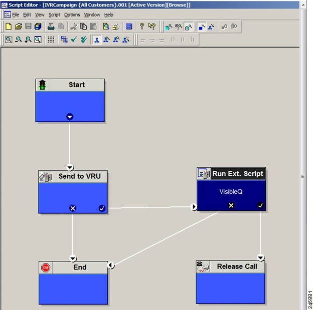
Send to VRU
The Send to VRU node can be used in a routing script for an IVR campaign. The following steps and accompanying diagram provide an example of how to create a script for an IVR campaign.
| Step 1 |
Using the Dialed Number tool, associate the MR dialed numbers with the configured call type. | ||
| Step 2 | Using the Script Editor Call Type Manager, associate the call type with the newly created reservation script.
|
Configure Skill Group
Perform the following steps to create a skill group using the Skill Group Explorer tool:
| Step 1 | In ICM Configuration Manager, open the Skill Group Explorer tool. |
| Step 2 | Make sure the PIM is displayed in the Select filter data section (for information on creating the PIM, see Configure the PG). |
| Step 3 | Click Retrieve. |
| Step 4 | Click Add Skill Group. |
| Step 5 | Set the Media Routing Domain to Cisco_Voice. |
| Step 6 | Enter a peripheral name and number (record them):____________________. (You can either enter a name or allow the system to generate the name.) |
| Step 7 | Check the ICM picks the agent check box. |
| Step 8 | Click Add Route. |
| Step 9 | Enter a name for the new route (any name is allowed). |
| Step 10 | Click Save. |
Create Dialed Number
Perform the following steps to create a dialed number for the MR PG.
| Step 1 | In ICM Configuration Manager, open the Dialed Number/Script Selector List tool. |
| Step 2 | Click Add, and then enter a dialed number for the MR PG. |
| Step 3 | Select the MR routing client from the drop-down list box. |
| Step 4 | Select Cisco_Voice from the Media Routing Domain drop-down list box. |
| Step 5 | Enter the dialed number. |
| Step 6 | On the Dialed Number Mapping tab, click Add. |
| Step 7 | In the Calling Line ID group box, click the All radio button. |
| Step 8 | In the Caller-entered digits group box, click the All radio button. |
| Step 9 | In the Call type drop-down list box, select the MR call type. |
| Step 10 | Click OK on the Dialed Number Map Entry dialog box, and then click Save. |
Note | To use the Personal Callback feature, a second dialed number is required. This dialed number must have the PersonalCallback dialed number string. As with the previous dialed number, map all Calling Line IDs and all Caller-entered digits to the call type previously created for the MR routing client. Multiple dialers require multiple dialed numbers—one for each routing client per skill group. |
Configure System Options
Use the Outbound Option System Options component in the Unified CCE Configuration Manager to define contact dialing time ranges to apply to all of your Outbound Option campaigns.
Be sure to select AM or PM for your start and end times.
| Step 1 | In Unified CCE Configuration Manager, expand Outbound Option, and then select System Options. |
| Step 2 | Click the General Options tab to define the dialing time range for all your Outbound Option campaigns to use, and then click OK. |
| Step 3 | Click the Bulk Update tab page to define specific dialing time ranges for telephone numbers, and then click Update All Campaigns. |
Enable Expanded Call Variables
Perform the following steps to enable the expanded call variables.
| Step 1 | Open the System Information tool in the Tools/Miscellaneous folder in the ICM Configuration Manager application. |
| Step 2 | In Unified CCE Administration, click . |
| Step 3 | Check the Expanded call context enabled check box. |
| Step 4 | Click Save. |
| Step 5 | Open the List tools. |
| Step 6 | Open the Expanded Call Variable List tool. |
| Step 7 | Click all BAxxxx variables (BAAccountNumber, BABuddyName, BACampaign, BADialedListID, BAResponse, BAStatus, and BATimezone). |
| Step 8 | In the Attributes tab, check the Enabled check box for each variable. |
| Step 9 | Click Save. |
(Optional) Configure Personal Callbacks
Personal Callback is an optional feature in Outbound Option. Personal Callback allows an agent to schedule a callback to a customer for a specific date and time. A personal callback connects the agent who originally spoke to the customer back to the customer at the customer-requested time.
This section describes how to configure your system to handle personal callbacks. Then, when your contact center users create campaigns, they enable the callback feature on a per campaign basis. The following table outlines the steps involved and lists which steps are described in detail below.
Note | All personal callbacks occur in Preview mode. Be aware that only one Dialer on a particular peripheral is assigned personal callback records. |
Some personal callback options must be configured through the registry. Furthermore, if a personal callback record is not associated with a campaign, it follows the rules configured within the registry.
| Step 1 | To enable Personal Callback, open the Unified CCE Configuration Manager. | |||||||||||||||||||||||||||||||||||||||||||
| Step 2 | Select Outbound Option. | |||||||||||||||||||||||||||||||||||||||||||
| Step 3 | Load the Campaign tool. | |||||||||||||||||||||||||||||||||||||||||||
| Step 4 | Select the Campaign General tab. | |||||||||||||||||||||||||||||||||||||||||||
| Step 5 | Open a predefined campaign. | |||||||||||||||||||||||||||||||||||||||||||
| Step 6 | Check the personal callback
check box.
Personal callback is now enabled. To configure the personal callback registry entries, continue with Step 7 of this procedure. | |||||||||||||||||||||||||||||||||||||||||||
| Step 7 | Configure a call type for personal callback. For information about creating call types, see "Call Types" in the Packaged CCE Administration Guide. | |||||||||||||||||||||||||||||||||||||||||||
| Step 8 | Create a dialed number with the name PersonalCallback on the outbound routing client. Refer to "Dialed Numbers" in the Packaged CCE Administration Guide for Release 9.0(x) for information about configuring dialed numbers. | |||||||||||||||||||||||||||||||||||||||||||
| Step 9 | In Script
Editor, create a routing script that sets up the Personal Callback reservation.
Include the following
nodes:
For example, the following Personal Callback reservation script uses nodes described in following sections: 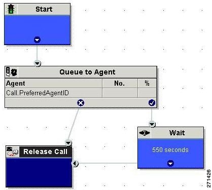 For details of routing scripts, refer to Set Up Routing Scripts. | |||||||||||||||||||||||||||||||||||||||||||
| Step 10 | Open regedit on the data server (DS). | |||||||||||||||||||||||||||||||||||||||||||
| Step 11 | Open HKEY_LOCAL_MACHINE\SOFTWARE\Cisco Systems, Inc.\ICM\<instance name>\LoggerA\BlendedAgent\CurrentVersion in the Outbound Option registry. | |||||||||||||||||||||||||||||||||||||||||||
| Step 12 | Configure the
personal callback registry entries listed in the following table. (Enter the
values in decimal format.)
| |||||||||||||||||||||||||||||||||||||||||||
| Step 13 | Create an enterprise skill group and an enterprise route. Then configure the Queue to Agent node. |
Create an Enterprise Skill Group
To use the Personal Callback feature, you need to create the enterprise skill group associated with the agent using the Enterprise Skill Group List tool.
| Step 1 | Open the List tools. |
| Step 2 | Open the Enterprise Skill Group List tool. |
| Step 3 | Create an enterprise skill group. In the Add Name field, type the enterprise name, then click Add. Select the skill group, and then click Save. |
| Step 4 | In the Attributes tab, click Add to add the skill group or groups. |
| Step 5 | Click Save. |
Create an Enterprise Route
After you create the enterprise skill group associated with the agent, you need to create an enterprise route using the Enterprise Route List tool. This route should target the enterprise skill group created in the previous step.
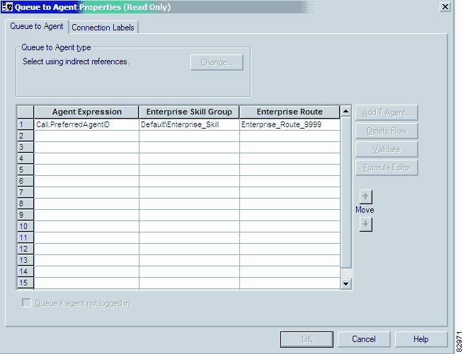
Configure Queue to Agent Node
| Step 1 | In Script Editor, double-click the Queue to Agent node. |
| Step 2 | Press Change in the Queue to agent type section. |
| Step 3 | Click Lookup agent reference by expression, then click OK. |
| Step 4 | In the agent expression column, enter Call.PreferredAgentID. |
| Step 5 | Select the enterprise skill group you created in the Enterprise Skill Group section (see Create an Enterprise Skill Group). If you are configuring for Unified SCCE, select the Route you configured in that section. |
| Step 6 | Select the enterprise route you created in the Enterprise Route section (see Create an Enterprise Route). |
| Step 7 | Confirm that the Peripheral column is left blank. |
| Step 8 | Click OK to save the Queue to Agent node. |
| Step 9 | Save and then
schedule the script. When scheduling the script, use the call type that is
configured for personal callback.
 |
Packet Capture
In order for SIP Dialer to properly capture data, you must ensure that the SIP Dialer on the call server machine is using the active interface from the Ethernet Interface list. You can find out which interface is the active interface by using a network protocol analyzer tool such as Wireshark, which you can download from www.wireshark.org. (From Wireshark, click Capture to open a Capture Interfaces dialog box; the listed interface with network packets is the active interface.)
You can change the SIP Dialer packet capture parameters to use the active interface from the Windows Registry Editor. Change the value of the interface name option (-i) in the CaptureOptions key to the number of the active interface. For example, to use the third interface, edit the value for -i to read -i 3.
Capture files are in the HKEY_LOCAL_MACHINE\SOFTWARE\Cisco Systems, Inc.\ICM\<customer instance>\Dialer registry key location.
- From a command prompt window, enter a procmon ba_capture command to specify that SIP Dialer use the active interface. In this command, specify the number of the active interface to use in the /options -i parameter.
The syntax of the procmon ba_capture command is as follows:
ba_capture [/on] [/off] [/options] [/type]
where
|
/on, /off |
/on turns packet capture on, /off turns packet capture off. The default is off; you should turn it on. |
|
/options |
|
|
/type |
/type 1 captures SIP packets only or /type 2 captures the entire data payload on the Dialer host machine. |
For example, the command
capture /on /options -i 2 -tt -C 20 –s 0 -W 20 -w DialerCapture
captures the network packets on interface 3 with capture files: capture1 – capture20. The maximum number of capture files stored is 20. After 20 files are created, the oldest capture file is overwritten with the new data. Maximum file size is 20 MB.
Unified Communications Manager and Gateway Configuration
The next phase of installing Outbound Option is configuring Unified Communications Manager and its related gateway.
The following table lists the steps that comprise Unified Communications Manager configuration and provides pointers to where the tasks are discussed.
|
Step Number |
Task |
IPCC Enterprise Procedure |
System PG Procedure |
|---|---|---|---|
|
1 |
Disable Ring Tone for Dialer Transfer |
||
|
2 |
Configure SIP Trunks |
- Disable Ringback During Transfer to Agent for SCCP
- Disable Ringback During Transfer to Agent for SIP
- Configuration of Voice Gateways, SIP Proxy, or Cisco Unified Border Element
- Configure SIP Trunks
Disable Ringback During Transfer to Agent for SCCP
Perform the following configuration so that customers do not hear a ringback tone while a call is being transferred to an agent.
Note | The following configuration is applicable to H323 only. You cannot disable Ringback for the Media Gateway Control Protocol (MGCP). |
| Step 1 | Log into the Unified CM Administration window. |
| Step 2 | Select . The Service Parameter Configuration screen appears. |
| Step 3 | On the Server and Service drop-down menus, select the Server and Service. For Service, specify Cisco CallManager. |
| Step 4 | Navigate to the Send H225 User Info Message drop-down menu. Select the Use ANN for Ringback option. |
| Step 5 | Click Save. |
| Step 6 | Repeat Steps 1 and 2. |
| Step 7 | On the Server and Service drop-down menus, select the Server and Service. For Service, specify Cisco IP Voice Media Streaming App. |
| Step 8 | Navigate to the Annunciator (ANN) parameters section of the screen. |
| Step 9 | On the Run Flag drop-down menu, select False. |
| Step 10 | Click Update. |
Disable Ringback During Transfer to Agent for SIP
The configuration for the SCCP Dialer does not work for the SIP Dialer. When the SIP Dialer is handing off the call to an agent, it sends REFER to the voice gateway. The voice gateway initiates a new SIP call (new INVITE) to CUCM, and then receives a 180 RINGING response. As a result, the gateway generates a ringback tone to the customer. With CUCM 8.5 and later, you can disable the ringback by applying a SIP normalization script to the CUCM SIP trunk. This script manipulates the 180 RINGING to a 183 SESSION PROGRESS message to prevent the gateway from generating a ringback.
Note |
|
| Step 1 | Navigate to https://<IP_address>:8443 where <IP_address> identifies the Unified Communications Manager server. |
| Step 2 | Log in to Unified Communications Manager |
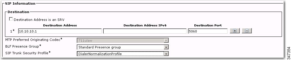
| Step 3 | To create a SIP
trunk in Unified Communications Manager with a SIP security profile for the
dialer agent transfer calls, select
.
The default
port is 5060.
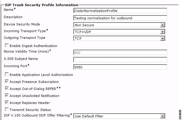 |
| Step 4 | Click Save. |
| Step 5 | Create a New SIP
trunk and associate the created SIP trunk Security Profile.
 |
| Step 6 | Click Save. |
| Step 7 | Click Reset. |
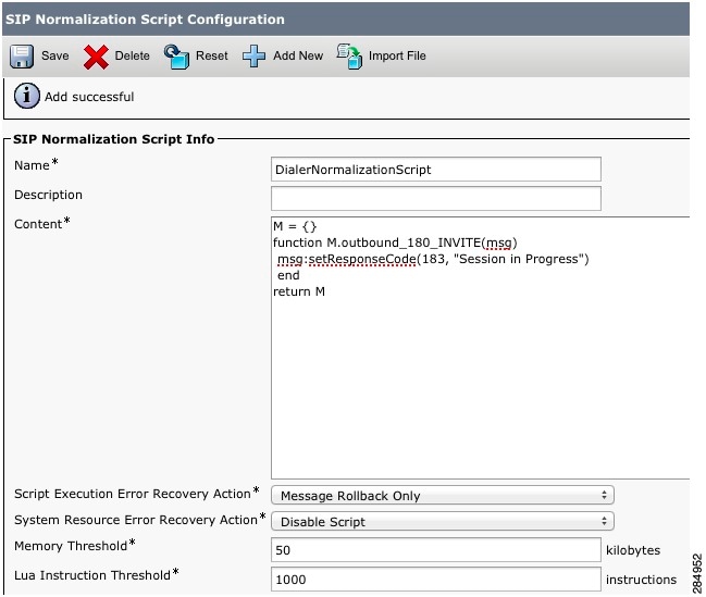
| Step 8 | In
, enter the following SIP
normalization script into the content field. All other values remain set to
default.
M = {}
function M.outbound_180_INVITE(msg)
msg:setResponseCode(183, "Session in Progress")
end
return M
 |
| Step 9 | Click Save. |
| Step 10 | Click Reset. |
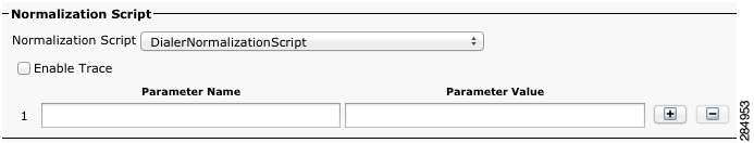
| Step 11 | Associate the
created normalization script with the SIP trunk.
 |
| Step 12 | Click Save. |
| Step 13 | Click Reset. |
Configuration of Voice Gateways, SIP Proxy, or Cisco Unified Border Element
In an Outbound Option deployment that uses the SIP Dialer, there are three possible types of configurations:
- The SIP Dialer is connected to a SIP Proxy such as Cisco Unified SIP Proxy. The SIP Proxy, in turn, is connected to voice gateway. It is possible for the SIP Proxy to be connected to more than one voice gateway; a configuration with multiple voice gateways is known as a server group.
- The SIP Dialer is connected directly to a voice gateway; no SIP Proxy is present. The voice gateway is configured with standard dial peer configuration so that the gateway knows how to direct traffic to agent extensions or to the IVR. This configuration is already commonly used for inbound calls.
Specify which configuration you are using when you install the Dialer component.
When you configure a voice gateway for use with Outbound Option, most of the default configuration values are sufficient. However, the following values must be specifically set. If you do not know these values, request the information from your voice network administrator.
- You must ensure 100rel is enabled for Outbound Option. Otherwise, Outbound calls from the SIP Dialer fail. 100rel is enabled globally on the gateway by default. However, 100rel cannot be enabled globally if Unified CVP calls are also routed with this gateway. When using Outbound Option on the same gateway as Unified CVP, disable 100rel globally with the command rel1xx disable and enable 100rel on the Outbound dial peer with the example dial-peer command: voice-class sip rel1xx supported "100rel".
- When configuring a voice gateway for use with the SIP Dialer, do not specify signaling forward unconditional under voice service voip. The SIP Dialer does not support this configuration. Instead, specify signaling forward none.
- Telecom carriers sometimes send ISDN alerting message without a progress indicator, which causes the voice gateway to send a SIP 180 Ringing message instead of a SIP 183 Session In Progress message to the SIP dialer. The SIP dialer has the capability to process provisional messages such as 180, 181, 182, and 183 with or without Session Description Protocol (SDP). When the SIP dialer receives these provisional messages without SDP, it does not perform Call Progress Analysis (CPA), and the Record CPA feature is disabled. To enable the SIP dialer to perform CPA, add the following configuration to the POTS dial-peer of the voice gateway so that a SIP 183 message is sent to the SIP dialer:"progress_ind alert enable 8".
- In some situations, the carrier may send an ISDN Connect message without an alerting message. In this case, the SIP Dialer disconnects the call because it receives 200 OK before a SIP 183 Session In Progress message. To correct this situation, add the configuration " progress_ind connect enable 8" to the POTS dial-peer of the voice gateway. This configuration causes the gateway to send the SIP 183 Session In Progress message before 200K.
You must ensure the 100rel SIP capability is enabled for Outbound Option. Otherwise, outbound calls from the SIP Dialer fail. The following two sections provide examples of voice gateway configuration from the command line.
Note | In an Outbound SIP dialer with Unified CVP IVR deployment, a call-survivability script enabled on an incoming POTS dial-peer in the Ingress gateway is not invoked during dialer-related call flows. Enabling a call-survivability script on an Inbound POTS dial-peer, however, does not negatively affect dialer-related call flows. |
If you are using a SIP Proxy, perform the following configuration on the SIP Proxy:
- Enable the SIP Dialer to reach the correct voice gateway for outbound calls.
- Enable the voice gateway to reach all of the applicable Unified CM/CVP nodes for calls transferred to an agent, an IVR, or to CVP.
- If your SIP proxy is connected to more than one voice gateway, you can optionally load balance between the voice gateways.
For detailed instructions on how to perform SIP Proxy configuration, see the Cisco Unified SIP Proxy documentation website at http://www.cisco.com/en/US/partner/products/ps10475/products_installation_and_configuration_guides_list.html.
Configure CUBE
Note | CUBE is only supported with SIP dialer when CPA is disabled. |
While configuring Cisco Unified Border Element, ensure that you:
- Disable the CPA on the terminating network or voice gateway when the Cisco Unified Border Element is connected to the voice gateway or any other terminating network.
-
Configure the three dial-peers in the Cisco Unified Border Element. The dial-peers are used for: - Issue the following commands globally to configure the Cisco Unified Border Element:
- Disable the Call Progress Analysis (CPA) for the SIP dialer to process these provisional messages: 180, 181, and 183 - with and without SDP. To disable the CPA, go to Configuration Manager > launch Outbound Option Campaign > Campaign Purpose tab > uncheck the Call Progress Analysis (CPA) checkbox.
Configure SIP Trunks
Unified CM is connected to the voice gateway or the SIP Proxy by SIP Trunks, which you configure on Unified CM.
Configure a SIP trunk on Unified CM from Unified CM to the voice gateway. Specify the IP address of the voice gateway in the Destination field. See also steps in this topic: Disable Ringback During Transfer to Agent for SIP.
| Step 1 | Configure these
trunks as follows:
See the Cisco Unified Communications Manager System Guide for instructions on how to configure SIP trunks. | ||||||||
| Step 2 | If your
Unified CM cluster
has more than two nodes, and you want to reach each node from both the voice
gateway and Cisco Unified SIP Proxy, configure the trunk to belong to a device
pool that points to the Communications Manager Publisher. This configuration
ensures that calls go to the agent if a Subscriber node fails over. See the
following configuration example:
For information about logging into Ingress or VXML gateways, refer to the "Courtesy Callback" chapter. Example: dial-peer voice 617 voip description catch all for refer destination-pattern 617T session protocol sipv2 session target ipv4:10.86.227.107 (CUCM Publisher) codec g711ulaw ! dial-peer voice 508 voip description catch all for refer destination-pattern 508T session protocol sipv2 session target ipv4:10.86.227.107 (CUCM Publisher) codec g711ulaw ! |
Outbound Option Software Installation Steps
This section discusses the tasks that are associated with installing Outbound Option and related components. Before proceeding, navigate to the side A data server and stop all ICM services there. Then perform the steps in the following sections.
- Software Installation and Database Creation
- Create Outbound Option Private Database
- Configure Logger
- Upgrade of an Outbound Option Database from a Previous Release
- Install Dialer Component on the PG Platform
- Modification of Local Static Route File
- Edit Dialer-Related Registry Values
- Install MR PG
- Installation of Cisco CTI Controls
Software Installation and Database Creation
The next phase in installing Outbound Option is Outbound Option component software installation and associated database creation. The following table lists the steps that comprise software installation and database creation and provides pointers to where the tasks are discussed.
|
Step Number |
Task |
Unified CCE Procedure |
System PG Procedure |
|---|---|---|---|
|
1 |
Install the Outbound Option private database on the Logger Side A platform |
||
|
2 |
Install the Dialer component on the PG platform |
||
|
3 |
Edit Dialer-related Registry values |
||
|
4 |
Install the MR PG on the PG platform |
Create Outbound Option Private Database
Note | It is important that you create the Outbound Option private database on side A only. |
| Step 1 | Collect the following information: |
| Step 2 | Estimate the contact table size using one of the following formulas: |
| Step 3 | Estimate the
dialing list table size using one of the following formulas:
|
| Step 4 | Calculate the
database size using this formula:
(Number of rows in all DL tables * (size of one row + size of index) ) + (Number of rows in personal call back table * (size of one row + size of index) ) + Sum of (Number of rows in Contact List table * (size of one row + size of index)) |
| Step 5 | Start ICMDBA by entering ICMDBA in the Microsoft Windows Run dialog box or command window. |
| Step 6 | Select the Logger and select . |
| Step 7 | In the Create Database window, specify the Outbound Option database type. Be sure to enable autogrow on the database. |
| Step 8 | Click
Add. The Add
Device window appears.
Use this window to create a new data device and log device for the Outbound Option database. Specify the disk drive letter and size in megabytes for each new device. Click OK to create the device, and then click Create. Click Start. At a later time, if necessary, you can edit the device to change storage size, or remove a device, using the option. |
| Step 9 | Click Close. |
 Caution | No manual changes to the contents of the outbound database are allowed. Do not use triggers in the outbound database. Triggers for the dialing lists or personal callback list should not be added or modified. The Dialer_Detail table in the HDS contains the information required by custom applications. Extract that information from the historical database server (HDS) to a separate server where the custom application can process the data without impacting the HDS. |
Configure Logger
Perform the following steps to configure the logger.
Upgrade of an Outbound Option Database from a Previous Release
If you are upgrading from a previous CCE/CCH release, you must run the Enhanced Database Migration Tool (EDMT) to upgrade your Outbound Option database. Otherwise, Campaign Manager will not start, and an alarm is triggered to indicate an incorrect private database version. See the Upgrade Guide for Cisco Unified ICM/Contact Center Enterprise & Hosted at http://www.cisco.com/en/US/products/sw/custcosw/ps1844/prod_installation_guides_list.html for instructions on running EDMT.
Install Dialer Component on the PG Platform
Perform the following steps to install the dialer component on the Side A PG platform.
| Step 1 | Make sure all ICM Services are stopped. | ||
| Step 2 | On both the call server side A and side B run Peripheral Gateway Setup. Type . | ||
| Step 3 | In the Cisco Unified ICM/Contact Center Enterprise & Hosted Setup dialog box, in the left column under Instances, select an instance. | ||
| Step 4 | Click
Add in the
Instance Components section.
The ICM Component Selection dialog box opens. | ||
| Step 5 | Click
Outbound Option
Dialer.
The Outbound Option Dialer Properties dialog box opens. | ||
| Step 6 | In the initial Dialer Properties dialog box, check Production mode and Auto start at system startup unless you are specifically told otherwise by your Unified ICM support provider. These options set the Dialer Service startup type to Automatic, so the dialer starts automatically when the machine starts up. | ||
| Step 7 | For Dialer Type, select the radio button for SIP (Session Initiation Protocol). | ||
| Step 8 | Click
Next.
| ||
| Step 9 | An Outbound
Option SIP Dialer Properties dialog box appears if you selected SIP as your Dialer Type. Supply the
following information on this page:
Click Next. | ||
| Step 10 | On the last
Outbound Option Dialer Properties dialog box, specify the following
information:
| ||
| Step 11 | Click Next. A Summary screen appears. | ||
| Step 12 | Verify that you have specified the correct information. Click
Back to
make corrections if needed; otherwise, click
Next to
begin dialer installation.
|
Modification of Local Static Route File
The SIP Dialer installation process installs an empty template file named DNPHost in the \icm\customerInstanceName\Dialer directory. This file defines the static route mappings of a dialed number wildcard pattern to the IP address or host name with which an agent phone or CTI Route point is registered. For each static route you wish to define, enter a row in this file in the following format:
wildcard pattern, IP address or host name, description
Examples:
7?????, 10.86.227.144, transferring outbound calls to agent extensions
86! , 10.86.227.186, for CTI Route Points on CUCM node1
4?????, gambino.cisco.com, transfer to IVR campaign
For single gateway deployments, the SIP Dialer reads the static routing info from DNPHost and uses the information from the file to construct the SIP REFER message. If the SIP Dialer is setup to support a voice gateway, the SIP Dialer loads DNPHost, ensures that it has valid routing entries, and sends an alarm if the file does not exist or is invalid.
See the installed DNPHost file template for additional information about its use.
Edit Dialer-Related Registry Values
After you finish installing the dialer component, perform the following dialer-related configuration:
- Configure the Dialer throttling on each Dialer in the system. Open ICM Configuration Manager, select , and then enter a value in the Port Throttle field. This field indicates the number of ports to throttle, which helps determine the calls per second rate at which the Dialer dials outbound calls. For example, a port throttle count=5 indicates that no more than 5 calls can be started during a one second period. If 5 calls are ready to be dialed, they are spaced evenly over that one second period. The total call capacity of Unified CM is dependent on several different factors, including the Unified CM version, inbound call rate, and outbound call rate. For more details, see the SNMP Guide for Cisco Unified ICM/Contact Center Enterprise & Hosted.
- After the dialer process runs for the first time, change the value of the AutoAnswerCall entry to 0 to disable the auto answer setting in the Dialer registry. See Auto Answer Configuration on Agent Phones for details about other options for auto answer that support agent notification of an incoming call.
Install MR PG
Perform the following steps to install the MR PG on the Side A platform.
| Step 1 | Run ICM Setup to install a PG that corresponds with PG2, which was configured earlier. |
| Step 2 | In the Peripheral Gateway Properties window, select the PG2 PG Node ID and the MediaRouting Client Type. |
| Step 3 | Click Next. |
| Step 4 | Add a PIM, PIM1. |
| Step 5 | In the MediaRouting Configuration window, enable the PIM. |
| Step 6 | Enter the peripheral name and the peripheral ID (recorded at the end of the procedure described in Configure Media Routing PG (MR PG)) of the MR_PIM. |
| Step 7 | Set the Application Hostname fields: |
| Step 8 | Set the Application Connection Port to the port number used by the Outbound Option Dialer (usually 38001). |
| Step 9 | Click Next until Setup finishes. When Setup finishes, click Finish. |
| Step 10 | Repeat the preceding steps to install the MR PG on the Side B PG platform. |
Installation of Cisco CTI Controls
This section describes the installation process for the Cisco CTI controls. It also describes how to install the Cisco CTI Toolkit Outbound Desktop (Win32) for Unified CCE.
Perform the following procedures to install CTI controls to support Outbound Option on the desktop.
See the CTI documentation available online at http://www.cisco.com.
- Integrate Outbound Option with CTI OS
- Configure CTI OS Server for Outbound Option
- Install CTI Toolkit Outbound Desktop (Win32)
- Integrate Outbound Option with Standard CTI Toolkit Agent Desktop
- Set Outbound Option Expanded Call Variables
Integrate Outbound Option with CTI OS
Outbound Option is fully compatible with the CTI OS CIL library and the CTI Toolkit Agent Desktop (Win32). While there are no Outbound Option-specific controls available for the CTI Toolkit Agent Desktop (Win32), a sample CTI OS Desktop (known as the "Cisco CTI Toolkit Outbound Desktop (Win32)"), which supports Outbound Option, is shipped with the product (located in <Drive Letter>:\Program Files\Cisco Systems\CTIOS Client\CTIOS Toolkit\Win32 CIL\Samples\CTI Toolkit Outbound Desktop). In addition, the standard CTI Toolkit Agent Desktop (Win32) can be modified to display all Outbound Option ECC variables in the call variable grid.
Note | Be aware that CTI OS Release 7.0(0) and greater uses CTI Protocol 11. As a result, there are more CTI fields available in CTI OS (for example, call type, CampaignID, and QueryRuleID). |
When installing, install the CTI OS Client, select the CTI Toolkit SDK and the Win32 check boxes to access the CTI Toolkit Outbound Desktop (Win32) sample. (See the "Install CTI Toolkit Outbound Desktop (Win32)" section for more details.)
If you are running Outbound Option with CTI OS, perform the following procedure to add Outbound Option ECC variables to CTI OS Server:| Step 1 | Log in to the CTI OS server. |
| Step 2 | Rename the <Drive Letter>:\ICM\CTIOS_bin\blendedagent_addecc.reg.txt file to blendedagent_addecc.reg. |
| Step 3 | Save the blendedagent_addecc.reg read-only file. Right-click the file, select Properties, and then uncheck the Read Only check box. |
| Step 4 | Edit the blendedagent_addecc.reg file and globally change "InstanceName" to the real system instance name and save it. |
| Step 5 | Double-click on theblendedagent_addecc.reg file to add the Outbound Option ECC variables to CTI OS. |
| Step 6 | In the Node Manager, restart the CTI OS service on the call server. |
| Step 7 | Restart all CTI OS Desktop clients to download the new ECC variables. |
What to Do Next
See the CTI OS System Manager's Guide for Cisco Unified ICM/Contact Center Enterprise & Hosted for more information. See CTI OS Outbound Option ECC Variable Settings for a sample .REG file which creates the applicable Outbound Option ECC registry entries. (This registry file must be edited and run on the CTI OS server.)
After the Outbound Option ECC variables have been added to the standard CTI Toolkit Agent Desktop (Win32), the values can be set through the grid. (See the "Outbound Option Extended Call Context Variables" section for a description of each ECC variable.)
Configure CTI OS Server for Outbound Option
If you are running Outbound Option with CTI OS, perform the following procedure to add Outbound Option expanded call variables to CTI OS Server:
| Step 1 | Log in to the CTI OS server. |
| Step 2 | Rename the <Drive Letter>:\ICM\CTIOS_bin\blendedagent_addecc.reg.txt file to blendedagent_addecc.reg. |
| Step 3 | Right-click the file, select Properties, and then uncheck the read-only check box. |
| Step 4 | Edit the blendedagent_addecc.reg file and globally change "InstanceName" to the system instance name from your Unified ICM setup. |
| Step 5 | Save the file. |
| Step 6 | Double-click the blendedagent_addecc.reg file to add the Outbound Option expanded call variables to CTI OS. |
| Step 7 | In the Node Manager, restart the CTI OS service on the call server. |
| Step 8 | Restart all CTI OS Desktop clients to automatically download the new expanded call variables. |
Install CTI Toolkit Outbound Desktop (Win32)
A sample CTI OS Desktop (known as the “Cisco CTI Toolkit Outbound Desktop (Win32)”), which supports Outbound Option, is shipped with the product. It is located in <Drive Letter>:\Program Files\Cisco Systems\CTIOS Client\CTIOS Toolkit\Win32 CIL\Samples\CTI Toolkit Outbound Desktop.
| Step 1 | Install CTI OS Client and confirm that the CTI Toolkit SDK and
Win32 check boxes are checked.
| ||
| Step 2 | Access the CTI Toolkit Outbound Desktop (Win32) from the following location: <Drive Letter>:\Program Files\Cisco Systems\CTIOS Client\CTIOS Toolkit\Win32 CIL\Samples\CTI Toolkit Outbound Desktop | ||
| Step 3 | Double-click the CTIOSOutOptSSoftphone.exe file. The CTI Toolkit Outbound Desktop (Win32) displays. |
Integrate Outbound Option with Standard CTI Toolkit Agent Desktop
Outbound Option is fully compatible with the CTI OS CIL library and the CTI Toolkit Agent Desktop (Win32). While there are no Outbound Option-specific controls available for the CTI Toolkit Agent Desktop (Win32), the standard CTI Toolkit Agent Desktop (Win32) can be modified to display all Outbound Option expanded call variables in the call variable grid.
Set Outbound Option Expanded Call Variables
After you add the Outbound Option expanded call variables to the standard CTI Toolkit Agent Desktop (Win32), you can set the values through the grid on the Agent Desktop with Outbound Option. When the agent logs in, the Outbound Option-related expanded call variables are visible. The agent can then change values for those variables.
Setup of Outbound Option in Cisco Desktop Administrator
This section provides information about setting up Outbound Option with Cisco Desktop Administrator. When using Outbound Option with Cisco Agent Desktop, outbound calls appear as inbound calls to the agent, and information about the call appears in the Enterprise Data pane.
See the CAD documentation available online at http://www.cisco.com for more information.
Outbound Option Enterprise Data
To enable Outbound Option enterprise data to appear in the Cisco Agent Desktop Enterprise Data window, the administrator must edit the Default layout to include some or all Outbound Option variables. These variables are prefixed with "BA." (Edit the default enterprise data layout in the Cisco Desktop Administrator.)
- BAAccountNumber [200]
- BABuddyName [201]
- BACampaign [202]
- BADialedListID [203]
- BAResponse [204]
- BAStatus [205]
- BATimeZone [206]
Note |
|
Add Enterprise Data Fields to Layout List
Use the following procedure to add the Outbound Option variables.
| Step 1 | Start Cisco Desktop Administrator. |
| Step 2 | In the navigation tree, navigate to the Layout Editor in the Enterprise Data window: Location > (logical contact center name) > Enterprise Data Configuration > Enterprise Data. Click Edit. |
| Step 3 | Add the following fields to the Layout List by selecting the field from the Available Fields List, and then clicking the left arrow button: |
| Step 4 | Click OK. |
| Step 5 | Click Apply to save your changes. |
Verification
This section provides a series of verification steps to determine if the system has been installed properly. These steps are designed to pinpoint problems that might exist in the setup before actually attempting to deploy the Dialer. If problems occur while using this product, please see this section before contacting Cisco Technical Support (TAC).
Note | This section assumes that the Outbound Option application is installed and at least one Dialer has been configured along with its associated port map. This section also assumes that the Dialer port map has been exported and configured on Unified CM using the BAT tool. |
- Dialer Component Status
- Verify Critical Configuration Steps
- Verify Database Configuration
- Verify Router Registry Key
Dialer Component Status
The Dialer component process status provides details about the health of the installation even before any campaign configuration is initiated or before any call is placed. You can view the Dialer component status in the Diagnostic Framework Portico.
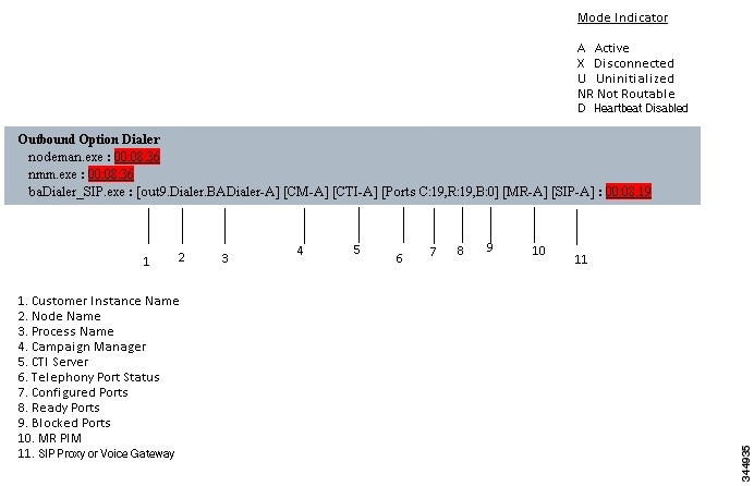
Customer Instance Name
The customer instance name shows the dialer’s customer instance, node name, and process name. This can be used if TAC asks you to interrogate the system while debugging a problem for a case.
Campaign Manager
The Campaign Manager shows the Campaign Manager connectivity status. This status is either A for active or X for disconnected. If the Campaign Manager connectivity status is X, the dialer is not connected to the Campaign Manager.
Try pinging from the dialer to the Campaign Manager machine by hostname and by IP Address.
- If the ping fails for the IP address, recheck that the IP address is correct and troubleshoot network connectivity.
- If the ping is successful for the IP address but not for the DNS hostname, check that the DNS hostname is correct and that it is properly configured in the system’s DNS server.
- If the ping is successful, then recheck the dialer component setup to see if the dialer component setup contains the wrong address or port number for the side A Logger.
- Check to see if the name of the Dialer configured in Configuration Manager matches the name entered during PG setup.
CTI Server
The third block shows CTI Server connectivity status. This status is either A for active or X for disconnected. If the status is X, then the dialer cannot connect to either CTI Server on side A or side B.
Try pinging from the dialer to the CTI Server/PG machines by hostname and by IP address.
- If the ping fails for the IP address:
- If the ping is successful for the IP address but not for the DNS hostname, check that the DNS hostname is correct and whether it is properly configured in the system’s DNS server.
- If the ping is successful, then recheck the dialer component set up to see if the dialer component set up contains the wrong address or port number for the CTI Server.
- Check that the PG is online. Check that the PG has been enabled properly in the ICM Router setup.
Ports
The fourth block shows the state of all dialer ports. The first value, C, shows the total number of configured ports. The second value, R, shows the total number of ready ports. Finally, the third value, B, reports the number of dialer ports that are blocked. (This is runtime activity; it is unusual for ports to be blocked.)
If the number of ports Configured is zero, then the dialer is not receiving port configuration from the Campaign Manager component. Check to verify that ports are configured properly.
If the number of Ready ports is zero, confirm that the PG has been started.
MR PIM
The next block shows connectivity status with the MR PIM. This status is either A for active, X for disconnected, or NR which means connected but not yet able to route. (The U status is rarely seen and indicates that a particular connectivity object within the dialer has not been created yet.)
- If the MR Status is X, check the connectivity by verifying the MR PG address and port configured in the dialer component setup.
If the MR PG status is NR, then the Media Routing connection is established. Check to see if the MR PG is online by looking at its status window.
SIP Dialer
The final block shows connectivity status with the SIP Proxy or Voice Gateway that is connected to the SIP dialer. This status is either A for active, X for disconnected, or D for heartbeat disabled.
Verify Critical Configuration Steps
Verify Database Configuration
The procedure for verifying that the database configuration is properly set up for SQL Server varies, depending on the installed version of SQL Server.
For SQL Server 2008 R2, perform the following steps:
| Step 1 | Open the SQL Server Management Studio. |
| Step 2 | Expand the databases. |
| Step 3 | Select the <cust instance_baA> Outbound Option database. Right click and select Properties. |
| Step 4 | Select the Files page. |
| Step 5 | In the database file row, click the button in the Autogrowth column. A Change Autogrowth dialog box appear. |
| Step 6 | Ensure that the Enable Autogrowth box is checked. Click OK. |
| Step 7 | In the log file row, click the button in the Autogrowth column. A Change Autogrowth dialog box appears. |
| Step 8 | Ensure that the Enable Autogrowth box is checked. Click OK. |
| Step 9 | Select the Options page. |
| Step 10 | On the Recovery Model drop-down menu, select Simple. |
| Step 11 | Click OK. |
Verify Router Registry Key
HKEY_LOCAL_MACHINE\SOFTWARE\Cisco Systems, Inc.\ICM\<customer
      instance>\RouterA/B\Router\
      CurrentVersion\Configuration\Global\SkillGroupCallsInQTimerInterval = 2
 Feedback