Cisco Unified Communications Manager Express SCCP Integration Guide for Cisco Unity Connection Release 14
Introduction
This document provides instructions for setting up a Cisco Unified Communications Manager Express Skinny Call Control Protocol (SCCP) integration with Cisco Unity Connection.
This document does not apply to the configuration in which Unity Connection is installed as Cisco Business Edition—on the same server with Cisco Unified Communications Manager.
Unity Connection can integrate with Cisco Unified CM Express in SRST mode. For details, see the Integrating Cisco Unity Connection with Cisco Unified CME-as-SRST application note at http://www.cisco.com/en/US/products/sw/voicesw/ps4625/products_installation_and_configuration_guides_list.html.
Integration Tasks
Before doing the following tasks to integrate Unity Connection with Cisco Unified CommunicationsManager Express by SCCP, confirm that Cisco Unity Connection is ready for the integration by completing the applicable tasks in the “Installing Cisco Unity Connection” chapter of the Install,Upgrade and Maintenance Guide for Cisco Unity Connection, Release 14, available at https://www.cisco.com/c/en/us/td/docs/voice_ip_comm/connection/14/install_upgrade/guide/b_14cuciumg.html.
The following task list describes the process for creating the integration.
Task List to Create the Integration
Use the following task list to set up a Cisco Unified CM Express SCCP integration.
-
Review the system and equipment requirements to confirm that all phone system and Unity Connection server requirements have been met. See the “Requirements” section.
-
Plan how the voice messaging ports are used by Unity Connection. See the “Planning the Usage of Voice Messaging Ports in Unity Connection” section .
-
Program Cisco Unified Communications Manager Express. See the “Programming the Cisco Unified Communications Manager Express Phone System” section .
-
Create the integration. See the “Creating a New Integration with Cisco Unified CM Express” section.
- Test the integration. See the “Testing the Integration” section.
-
If this integration is a second or subsequent integration, add the applicable new user templates for the new phone system. See the “Adding New User Templates for Multiple Integrations” section.

Note
While integrating the Cisco Unity Connection with Cisco Unified Call Manager through a SCCP uncheck the Synchronize guest time to host option for Unified Communications product line in Virtualized environment. This enables the Unified Communications to synchronize with their clock to external NTP servers.
Requirements
The Cisco Unified CM Express SCCP integration supports configurations of the following components:
Phone System
-
A compatible version of Cisco Unified CM Express.
For details on compatible versions of Cisco Unified CM Express, see the Compatibility Matrix for Cisco Unity Connectionat
http://www.cisco.com/en/US/products/ps6509/products_device_support_tables_list.html. - The following phones or
combinations of phones for the Cisco Unified CM Express extensions:
- Only SCCP phones.
- Both SCCP phones and SIP phones.
For a list of supported Cisco IP phone models, see the applicable compatibility information document at http://www.cisco.com/en/US/products/sw/voicesw/ps4625/products_device_support_tables_list.html.
-
A compatible Cisco IOS software version. See the Cisco Unified CME and Cisco IOS Software Version Compatibility Matrix at
http://www.cisco.com/en/US/products/sw/voicesw/ps4625/products_device_support_tables_list.html.
- Cisco Unified CM Express feature license.
-
Cisco IP phone feature licenses, and Cisco licenses for other H.323-compliant devices or software(such as Cisco Virtual phone and Microsoft NetMeeting clients) that are connected to the network,as well as one license for each Unity Connection port.
-
Analog phones connected to ATA. (For integration limitations with these phones, see the “Integration Description”.)
- A LAN Unity Connection in each location where you plug the applicable phone into the network.
Unity Connection Server
-
The applicable version of Unity Connection. For details on compatible versions of UnityConnection, see the Compatibility Matrix for Cisco Unity Connection at http://www.cisco.com/en/US/products/ps6509/products_device_support_tables_list.html.
-
Unity Connection installed and ready for the integration, as described in the “Installing Cisco Unity Connection” chapter of the Install, Upgrade and Maintenance Guide for Cisco Unity Connection, Release 14, available at https://www.cisco.com/c/en/us/td/docs/voice_ip_comm/connection/14/install_upgrade/guide/b_14cuciumg.html.
- A license that enables the applicable number of voice messaging ports.
Centralized Voice Messaging
Unity Connection supports centralized voice messaging through the phone system, which supportsvarious inter-phone system networking protocols including proprietary protocols such as Avaya DCS,Nortel MCDN, or Siemens CorNet, and standards-based protocols such as QSIG or DPNSS. Note that centralized voice messaging is a function of the phone system and its inter-phone system networking,not voicemail. Unity Connection supports centralized voice messaging as long as the phone system andits inter-phone system networking are properly configured. For details, see the “Centralized Voice Messaging” section in the “Integrating Cisco Unity Connection with the Phone System” chapter of the Design Guide for Cisco Unity Connection , Release 14 at https://www.cisco.com/c/en/us/td/docs/voice_ip_comm/connection/14/design/guide/b_14cucdg.html.
Integration Description
The Cisco Unified Communications Manager (CM) Express SCCP integration uses a LAN to connect Unity Connection and the phone system. The Cisco Unified Communications Manager Express router also provides connections to the PSTN. Figure 1 shows the connections for a system with a single Cisco Unified CM Express router.
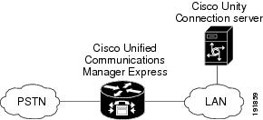
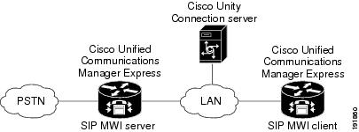
Figure 2 shows the connections for a system with multiple Cisco Unified CM Express router and a single Unity Connection server. One Cisco Unified CM Express router acts as the SIP MWI server, and the remaining Cisco Unified CM Express routers act as SIP MWI clients. Note that Cisco Unity Connection voice messaging ports register with only the SIP MWI server (the Cisco Unified CM Express router that is on the same LAN as the Unity Connection server), not with the SIP MWI clients.
For a list of supported versions of Cisco Unified CM Express that are qualified to integrate with Unity Connection by Skinny Call Control Protocol (SCCP), see the Compatibility Matrix for Cisco Unity Connection at http://www.cisco.com/en/US/products/ps6509/products_device_support_tables_list.html.
This document does not apply to the configuration in which Unity Connection is installed as Cisco Business Edition—on the same server with Cisco Unified CM.
Call Information
The phone system sends the following information with forwarded calls:
-
The extension of the called party
-
The extension of the calling party (for internal calls) or the phone number of the calling party (if it is an external call and the system uses caller ID)
- The reason for the forward (the extension is busy, does not answer, or is set to forward all calls)
Unity Connection uses this information to answer the call appropriately. For example, a call forwarded to Unity Connection is answered with the personal greeting of the user. If the phone system routes the call to Unity Connection without this information, Unity Connection answers with the opening greeting.
Integration Functionality
The Cisco Unified CM Express SCCP integration with Cisco Unity Connection provides the following features:
-
Call forward to personal greeting
- Call forward to busy greeting
- Caller ID
-
Easy message access (a user can retrieve messages without entering an ID; Unity Connection identifies a user based on the extension from which the call originated; a password may be required)
-
Identified user messaging (Unity Connection automatically identifies a user who leaves a message during a forwarded internal call, based on the extension from which the call originated)
- Message waiting indication (MWI)
These integration features are not available to analog phones connected through FXS ports on the CiscoUnified CM Express phone system. Analog phones connected to ATA, however, support all integration features, except MWIs (MWI lamps do not light, though the stutter dial tone sounds).
Integrations with Multiple Phone Systems
When Unity Connection is installed as Cisco Business Edition—on the same server with Cisco Unified Communications Manager—Unity Connection cannot be integrated with multiple phone systems at one time.
When Unity Connection is not installed as Cisco Business Edition, Unity Connection can be integrated with two or more phone systems at one time. For information on and instructions for integrating Cisco Unity Connection with multiple phone systems, see the Multiple Phone System Integration Guide for Cisco Unity Connection Release 14 at
Planning the Usage of Voice Messaging Ports in Unity Connection
Before programming the phone system, you need to plan how the voice messaging ports are used by Unity Connection. The following considerations affect the programming for the phone system (for example, setting up the hunt group or call forwarding for the voice messaging ports):
-
The number of voice messaging ports installed.
For a Unity Connection cluster, each Unity Connection server must have enough ports to handle all voice messaging traffic in case the other server stops functioning. The Cisco Unified CM Express server must have enough ports created for all Unity Connection servers.
- The number of voice messaging ports that answer calls.
-
The number of voice messaging ports that only dial out, for example, to send message notification, to set message waiting indicators (MWIs), and to make telephone record and playback (TRAP) connections.
The following table describes the voice messaging port settings in Unity Connection that can be set on Telephony Integrations > Port of Cisco Unity Connection Administration.
|
Field |
Considerations |
|---|---|
|
Enabled |
Check this check box to enable the port. The port is enabled during normal operation. Uncheck this check box to disable the port. When the port is disabled, calls to the port get a ringing tone but are not answered. Typically, the port is disabled only by the installer during testing. |
|
Server |
(For a Unity Connection cluster only) Select the name of the Unity Connection server that you want to handle this port. Assign an equal number of answering and dial-out voice messaging ports to the Unity Connection servers so that they equally share the voice messaging traffic. |
|
Extension |
Enter the extension for the port as assigned on the phone system. |
|
Answer Calls |
Check this check box to designate the port for answering calls. These calls can be incoming calls from unidentified callers or from users. |
|
Perform Message Notification |
Check this check box to designate the port for notifying users of messages. Assign Perform Message Notification to the least busy ports. |
|
Send MWI Requests |
Check this check box to designate the port for turning MWIs on and off. Assign Send MWI Requests to the least busy ports. |
|
Allow TRAP Connections |
Check this check box so that users can use the port for recording and playback through the phone in Unity Connection web applications. Assign Allow TRAP Connections to the least busy ports. |
|
Outgoing Hunt Order |
Enter the priority order in which Unity Connection uses the ports when dialing out (for example, if the Perform Message Notification, Send MWI Requests, or Allow TRAP Connections check box is checked). The highest numbers are used first. However, when multiple ports have the same Outgoing Hunt Order number, Unity Connection uses the port that has been idle the longest. |
Determining the Number of Voice Messaging Ports to Install
The number of voice messaging ports to install depends on numerous factors, including:
-
The number of calls Unity Connection answers when call traffic is at its peak.
- The expected length of each message that callers record and that users listen to.
- The number of users.
- The number of ports that are set to dial out only.
- The number of calls made for message notification.
- The number of MWIs that are activated when call traffic is at its peak.
-
The number of TRAP connections needed when call traffic is at its peak. (TRAP connections are
used by Unity Connection web applications to play back and record over the phone.)
- The number of calls that use the automated attendant and call handlers when call traffic is at its peak.
-
Whether a Unity Connection cluster is configured. For considerations, see the “Considerations for a Unity Connection Cluster” section.
It is best to install only the number of voice messaging ports that are needed so that system resources are not allocated to unused ports.
Determining the Number of Voice Messaging Ports to Answer Calls
The calls that the voice messaging ports answer can be incoming calls from unidentified callers or from users. Typically, the voice messaging ports that answer calls are the busiest.
You can set voice messaging ports to both answer calls and to dial out (for example, to send message notifications). However, when the voice messaging ports perform more than one function and are very active (for example, answering many calls), the other functions may be delayed until the voice messaging port is free (for example, message notifications cannot be sent until there are fewer calls to answer). For best performance, dedicate certain voice messaging ports for only answering incoming calls, and dedicate other ports for only dialing out. Separating these port functions eliminates the possibility of a collision, in which an incoming call arrives on a port at the same time that Unity Connection takes the port off-hook to dial out.
If your system is configured for a Unity Connection cluster, see the “Considerations for a Unity Connection Cluster” section.
Determining the Number of Voice Messaging Ports to Dial Out
Ports that only dial out and not answer calls can do one or more of the following:
-
Notify users by phone, pager, or email of messages that have arrived.
- Turn MWIs on and off for user extensions.
-
Make a TRAP connection so that users can use the phone as a recording and playback device in Unity Connection web applications.
Typically, these voice messaging ports are the least busy ports.
If your system is configured for a Unity Connection cluster, see the “Considerations for a Unity Connection Cluster” section.
 Caution |
In programming the phone system, do not send calls to voice messaging ports in Unity Connection that cannot answer calls (voice messaging ports that are not set to Answer Calls). For example, if a voice messaging port is set only to Send MWI Requests, do not send calls to it. |
Considerations for a Unity Connection Cluster
If your system is configured for a Unity Connection cluster, consider how the voice messaging ports are used in different scenarios.
When Both Unity Connection Servers are Functioning
-
The phone system is provisioned with twice the number SCCP ephone devices needed to handle the voice messaging traffic.
-
A hunt group is configured on the phone system to send incoming calls first to the subscriber server, then to the publisher server if no answering ports are available on the subscriber server.
- Both Unity Connection servers are active and handle voice messaging traffic for the system.
-
In Cisco Unity Connection Administration, the voice messaging ports that connect to the SCCP ephone devices are configured so that an equal number of voice messaging ports are assigned to each Unity Connection server. This guide directs you to assign the voice messaging ports to their specific server at the applicable time.
- The voice messaging ports on both Unity Connection servers are registered with the phone system.
-
The number of voice messaging ports that are assigned to one Unity Connection server must be sufficient to handle all of the voice messaging traffic for the system (answering calls and dialing out) when the other Unity Connection server stops functioning.
If both Unity Connection servers must be functioning to handle the voice messaging traffic, the system do not have sufficient capacity when one of the servers stops functioning.
-
Each Unity Connection server is assigned half the total number of voice messaging ports.
If all the voice messaging ports are assigned to one Unity Connection server, the other Unity Connection server cannot answer calls or to dial out.
-
Each Unity Connection server must have voice messaging ports that answer calls and can dial out
(for example, to set MWIs).
When Only One Unity Connection Server is Functioning
-
The SCCP ephone devices on the phone system are unregistered from the voice messaging ports on the Unity Connection server that stopped functioning.
- The hunt group on the phone system sends all calls to the functioning Unity Connection server.
- The functioning Unity Connection server receives all voice messaging traffic for the system.
-
The number of voice messaging ports that are assigned to the functioning Unity Connection server must be sufficient to handle all of the voice messaging traffic for the system (answering calls and dialing out).
-
The functioning Unity Connection server must have voice messaging ports that answer calls and can dial out (for example, to set MWIs).
If the functioning Unity Connection server does not have voice messaging ports for answering calls, the system cannot answer incoming calls. Similarly, if the functioning Unity Connection server does not have voice messaging ports for dialing out, the system cannot dial out (for example, to set MWIs).
Programming the Cisco Unified Communications Manager Express Phone System
After the Cisco Unified Communications Manager Express router is installed, do the procedures in the applicable section depending on the Unity Connection configuration or on the number of Cisco Unified CM Express routers that you integrate with Unity Connection:
-
Unity Connection without a cluster—see the “Programming a Cisco Unified Communications Manager Express Router to Integrate with Unity Connection (without a Cluster)” section.
-
Unity Connection with a cluster configured—see the “Programming a Cisco Unified Communications Manager Express Router to Integrate with a Unity Connection Cluster” section.
-
Multiple Cisco Unified Communications Manager Express routers—see the “Programming Multiple Cisco Unified Communications Manager Express Routers to Integrate with Unity Connection” section.
Programming a Cisco Unified Communications Manager Express Router to Integrate with Unity Connection (without a Cluster)
This procedure configures the Message button on Cisco IP phones to dial the Unity Connection pilot number when pressed.
Note |
Do the procedures in this section only if you are integrating a single Cisco Unified CM Express router with Unity Connection server (without a Unity Connection cluster). If Cisco Unity Connection is configured for a Unity Connection cluster, see the “Programming a Cisco Unified Communications Manager Express Router to Integrate with a Unity Connection Cluster” section. If you are integrating multiple Cisco Unified CM Express routers, see the “Programming Multiple Cisco Unified Communications Manager Express Routers to Integrate with Unity Connection” section. |
Configuring the Message Button Access to Unity Connection (without a Cluster)
Procedure
| Step 1 |
On the Cisco Unified CM Express router, go into the telephony-service configuration mode by entering the following command: telephony-service
|
| Step 2 |
Enter the following command: voicemail <Cisco Unity Connection pilot number> |
| Step 3 |
To exit the telephony-service configuration mode, enter the following command: exit
|
Example
The following is an example of the configuration:
telephony-service
voicemail 4001
Configuring the Router for Unity Connection (without a Cluster)
Procedure
| Step 1 |
Go into the ephone-dn configuration mode and configure the directory number tag for the Cisco IP phone lines by entering the applicable command:
|
||
| Step 2 |
To set the extension number for the voice messaging port, enter the following command: number <Voice messaging port extension>
|
||
| Step 3 |
To set the display name for the port (for example, “Voice Messaging System” or “Dial Out Only”), enter the following command: name <Display name of voice messaging port> |
||
| Step 4 |
To set the device name for the port (for example, “CUC1-VI1” or “CUC1-Dialout1”), enter the following command: description <Device name
of voice messaging port>
|
||
| Step 5 |
To reserve the second ephone-dn channel for supervised transfers, enter the following command: huntstop channel
|
||
| Step 6 |
To set the dial-peer preference for the extension, enter the following command: preference <Preference
order>
|
||
| Step 7 |
Enter the applicable command:
|
||
| Step 8 |
Repeat 1 through 7 for all remaining ports.
|
||
| Step 9 |
To exit the ephone-dn configuration mode, enter the following command: exit
|
Example
The following is an example of the configuration without a Unity Connection cluster:
ephone-dn 32 dual-line
number 4001
name "Voice Messaging System"
description "CUC1-VI1"
huntstop channel
no huntstop
preference 1
!
ephone-dn 33 dual-line
number 4001
name "Voice Messaging System"
description "CUC1-VI2"
huntstop channel
no huntstop
preference 2
!
ephone-dn 34 dual-line
number 4001
name "Voice Messaging System"
description "CUC1-VI3"
huntstop channel
huntstop
preference 3
!
ephone-dn 35
number 5001
name "Dial Out Only"
description "CUC1-Dialout1"
In this example, there are four ephone-dns configured to provide four voice messaging ports. Three of the ephone-dns are configured with the same extension number to provide ports dedicated for leaving and retrieving voice messages. These three ephone-dns are also configured with two channels each (the second channel is reserved for supervised transfers). The fourth ephone-dn is provided for use as a dial-out port. The first three ephone-dns are configured with the same extension number (4001), using preferences 1, 2, and 3 to create a hunt group. If the first port is busy, the call goes to the second port, and so on. Port 4 is configured with the extension number 5001 and is used to dial out by Unity Connection (for example, to set MWIs). Separate ports are required for answering calls and dialing out in order to prevent call-collision problems between incoming calls placed by Cisco Unified CM Express to Unity Connection, and outgoing calls that Unity Connection places in the opposite direction.
Associating the Voice Messaging Port (Without a Unity Connection Cluster)
To associate the actual voice messaging port (vm-device-id) to the phone number, associate the Cisco IP phone with the voice messaging port.
The vm-device-id name uses the following format:
<Unity Connection device name prefix><Port number>
The vm-device-id name must match the Unity Connection voice messaging port name that you use to identify the port in Cisco Unity Connection Administration when you create the integration:
-
The Unity Connection device name prefix part (for example, CUC1-VI) must match the Device Name Prefix field on the Telephony Integrations > Port Group > Port Group Basics page of Cisco Unity Connection Administration.
-
The port number part (for example, “1”) must match the number part of the Cisco Unity Connection Administration voice messaging port name used to identify the port on the Telephony Integrations > Port > Port Basics page of Cisco Unity Connection Administration.
Associating a Voicemail Port to Cisco Unified CM Express Router
Procedure
| Step 1 |
Go into the ephone configuration mode and register the Cisco IP phones by entering the following command: ephone <DN tag>
|
||
| Step 2 |
Define the voice messaging port name, by entering the following command: vm-device-id <Cisco Unity Connection device name prefix><Port number> For example, if the Unity Connection device name prefix is CUC1-VI, enter CUC1-VI1 for the first port, CUC1-VI2 for the second port, and so on.
|
||
| Step 3 |
Assign buttons to the Cisco IP phone directory numbers created in the “Configuring the Router for Unity Connection (without a Cluster)” procedure. by entering the following command: button <Button number>:<DN tag> For example, you can use the values 1:1, 2:4, or 3:14. In this example, button 1 corresponds to directory number 1 (ephone-dn 1), button 2 corresponds to directory number 4, and button 3 corresponds to directory number 14. The buttons correspond to the phone lines on the Cisco IP phone. |
||
| Step 4 |
Repeat 1 through 3 for all remaining voice messaging port names.
|
||
| Step 5 |
To exit the ephone configuration mode, enter the following command: exit |
Example
Following is an example of the configuration without a Cisco Unity Connection cluster. In this example, the vm-device-id command is used within the ephone configuration in place of the mac-address parameter that is used for configuring a regular Cisco IP phone.
ephone 5
vm-device-id CUC1-VI1
button 1:32
!
ephone 6
vm-device-id CUC1-VI2
button 1:33
!
ephone 7
vm-device-id CUC1-VI3
button 1:34
!
ephone 8
vm-device-id CUC1-VI4
button 1:35
Configuring a Directory Number for MWI Notification (Without a Unity Connection Cluster)
MWI configuration on the Cisco Unified CM Express is performed by dedicating Cisco IP phone directory numbers (ephone-DNs) to process MWI status notification calls originating from Unity Connection. You must allocate a minimum of one MWI processing ephone-dn for each MWI ephone-dn voice messaging port. The MWI processing ephone-dn extensions are configured to match the MWI extensions configured on Unity Connection.
Procedure
| Step 1 |
Go into the ephone-dn configuration mode and configure the directory numbers for the Cisco IP phone lines by entering the following command: ephone-dn <DN
tag>
|
||
| Step 2 |
Configure two valid directory numbers for the Cisco IP phone to be used for MWIs—the first number turns MWIs on, and the second number turns MWIs off—by entering the following command: number <MWI on
number> secondary <MWI off number>
|
||
| Step 3 |
Configure these two directory numbers to be used for setting MWIs by entering the following command: mwi on-off
|
||
| Step 4 |
To exit the ephone-dn configuration mode, enter the following command: exit
|
Example
Following is an example of the configuration.
ephone-dn 32
number 8000 secondary 8001
mwi on-off
In this example, Unity Connection calls extensions 8000 and 8001 to turn MWIs on and off. The DN triggers an MWI ON event when 8000 is called, and an MWI OFF event when 8001 is called.
For extensions associated with analog telephone adaptors (ATAs), the MWI is a lit function button on the ATA and a stutter dial tone on the connected analog phone.
Note |
After completing the procedures in this section, continue to the “Creating a New Integration with Cisco Unified CM Express” section. |
Programming a Cisco Unified Communications Manager Express Router to Integrate with a Unity Connection Cluster
This procedure configures the Message button on Cisco IP phones to dial the Unity Connection pilot number when pressed.
Note |
Do the procedures in this section only if you are integrating a single Cisco Unified CM Express router with Unity Connection with a Unity Connection cluster configured. If Unity Connection is not configured for a Unity Connection cluster, see the “Programming a Cisco Unified Communications Manager Express Router to Integrate with Unity Connection (without a Cluster)” section. If you are integrating multiple Cisco Unified CM Express routers, see the “Programming Multiple Cisco Unified Communications Manager Express Routers to Integrate with Unity Connection” section. |
Configuring the Message Button Access to a Unity Connection Cluster
Procedure
| Step 1 |
On the Cisco Unified CM Express router, go into the telephony-service configuration mode by entering the following command: telephony-service |
| Step 2 |
Enter the following command: voicemail <Cisco Unity Connection pilot number> |
| Step 3 |
To exit the telephony-service configuration mode, enter the following command: exit |
Example
The following is an example of the configuration:
telephony-service
voicemail 4001
Configuring the Router for a Unity Connection Cluster
Procedure
| Step 1 |
Go into the ephone-dn configuration mode and configure the directory number tag for the Cisco IP phone lines by entering the applicable command:
|
||
| Step 2 |
To set the extension number for the voice messaging port, enter the following command: number <Voice messaging port extension>
|
||
| Step 3 |
To set the display name for the port (for example, “Voice Messaging System” or “Dial Out Only”), enter the following command: name <Display name of voice messaging port> |
||
| Step 4 |
To set the device name for the port (for example, “CUC1-VI1” or “CUC1-Dialout1”), enter the following command: description <Device name of voice messaging port> |
||
| Step 5 |
To reserve the second ephone-dn channel for supervised transfers, enter the following command: huntstop channel |
||
| Step 6 |
To set the dial-peer preference for the extension, enter the following command: preference <Preference order>
|
||
| Step 7 |
Enter the applicable command:
|
||
| Step 8 |
Repeat 1 through 7 for all remaining ports.
|
||
| Step 9 |
To exit the ephone-dn configuration mode, enter the following command: exit
|
Example
The following is an example of the configuration with a Unity Connection cluster configured:
ephone-dn 32 dual-line
number 4001
name "Voice Messaging System"
description "CUC1-VI1"
huntstop channel
no huntstop
preference 4
!
ephone-dn 33 dual-line
number 4001
name "Voice Messaging System"
description "CUC1-VI2"
huntstop channel
no huntstop
preference 5
!
ephone-dn 34 dual-line
number 4001
name "Voice Messaging System"
description "CUC1-VI3"
huntstop channel
huntstop
preference 6
!
ephone-dn 35 dual-line
number 4001
name "Voice Messaging System"
description "CUC2-VI1"
huntstop channel
no huntstop
preference 1
!
ephone-dn 36 dual-line
number 4001
name "Voice Messaging System"
description "CUC2-VI2"
huntstop channel
no huntstop
preference 2
!
ephone-dn 37 dual-line
number 4001
name "Voice Messaging System"
description "CUC2-VI3"
huntstop channel
no huntstop
preference 3
!
ephone-dn 38
number 5001
name "Dial Out Only"
description "CUC1-Dialout1"
!
ephone-dn 39
number 5001
name "Dial Out Only"
description "CUC2-Dialout1"
In this example, there are two sets of ephone-dns:
-
Four ephone-dns are configured for the publisher server in the Unity Connection cluster (CUC1-VI1
through CUC1_VI3, and CUC1-Dialout1).
-
Four ephone-dns are configured for the subscriber server in the Unity Connection cluster
(CUC2-VI1 through CUC2_VI3, and CUC2-Dialout1).
The hunt group routes calls first to the subscriber server in the Unity Connection cluster. When all the answering ports on the subscriber server are busy, the hunt group routes calls to the publisher server.Only the last answering ephone-dn for the publisher server has enabled huntstop so that the hunt group searches through the answering ephone-dns on all Unity Connection servers. The ephone-dns that are used for dialing out are not included in the hunt group.
Associating the Voice Messaging Port (With a Unity Connection Cluster Configured)
To associate the actual voice messaging port (vm-device-id) to the phone number, associate the Cisco IP phone with the voice messaging port.
The vm-device-id name uses the following format:
<Unity Connection device name prefix><Port number>
The vm-device-id name must match the Unity Connection voice messaging port name that you use to identify the port in Cisco Unity Connection Administration when you create the integration:
-
The Unity Connection device name prefix part (for example, CUC1-VI) must match the Device Name Prefix field on the Telephony Integrations > Port Group > Port Group Basics page ofCisco Unity Connection Administration.
-
The port number part (for example, “1”) must match the number part of the Cisco Unity Connection Administration voice messaging port name used to identify the port on the Telephony Integrations > Port > Port Basics page of Cisco Unity Connection Administration.
Associating a Voice Messaging Port to Cisco Unified CM Express Router
Procedure
| Step 1 |
Go into the ephone configuration mode and register the Cisco IP phones by entering the following command: ephone <DN tag> |
||
| Step 2 |
Define the voice messaging port name, by entering the following command: vm-device-id <Cisco Unity Connection device name prefix><Port number> For example, if the Cisco Unity Connection device name prefix is CUC1-VI, enter CUC1-VI1 for the first port, CUC1-VI2 for the second port, and so on.
|
||
| Step 3 |
Assign buttons to the Cisco IP phone directory numbers created in the “Configuring the Router for a Unity Connection Cluster” by entering the following command: button <Button number>:<DN tag> For example, you can use the values 1:1, 2:4, or 3:14. In this example, button 1 corresponds to directory number 1 (ephone-dn 1), button 2 corresponds to directory number 4, and button 3 corresponds to directory number 14. The buttons correspond to the phone lines on the Cisco IP phone. |
||
| Step 4 |
Repeat 1 through 3 for all remaining voice messaging port names.
|
||
| Step 5 |
To exit the ephone configuration mode, enter the following command: exit |
Example
The following is an example of the configuration with a Unity Connection cluster. In this example, the vm-device-id command is used within the ephone configuration in place of the mac-address parameter that is used for configuring a regular Cisco IP phone.
ephone 5
vm-device-id CUC1-VI1
button 1:32
!
ephone 6
vm-device-id CUC1-VI2
button 1:33
!
ephone 7
vm-device-id CUC1-VI3
button 1:34
!
ephone 8
vm-device-id CUC1-VI4
button 1:38
!
ephone 9
vm-device-id CUC2-VI1
button 1:35
!
ephone 10
vm-device-id CUC2-VI2
button 1:36
!
ephone 11
vm-device-id CUC2-VI3
button 1:37
!
ephone 12
vm-device-id CUC2-VI4
button 1:39
Configuring a Directory Number for MWI Notification (With a Unity Connection Cluster Configured)
MWI configuration on the Cisco Unified CM Express is performed by dedicating Cisco IP phone directory numbers (ephone-DNs) to process MWI status notification calls originating from Unity Connection. You must allocate a minimum of one MWI processing ephone-dn for each MWI ephone-dn voice messaging port. The MWI processing ephone-dn extensions are configured to match the MWI extensions configured on Unity Connection.
Procedure
| Step 1 |
Go into the ephone-dn configuration mode and configure the directory numbers for the Cisco IP phone lines by entering the following command: ephone-dn <DN tag> |
||
| Step 2 |
Configure two valid directory numbers for the Cisco IP phone to be used for MWIs—the first number turns MWIs on, and the second number turns MWIs off—by entering the following command: number <MWI on number> secondary <MWI off number>
|
||
| Step 3 |
Configure these two directory numbers to be used for setting MWIs by entering the following command: mwi on-off |
||
| Step 4 |
To exit the ephone-dn configuration mode, enter the following command: exit |
Example
Following is an example of the configuration.
ephone-dn 32
number 8000 secondary 8001
mwi on-off
In this example, Unity Connection calls extensions 8000 and 8001 to turn MWIs on and off. The DN triggers an MWI ON event when 8000 is called, and an MWI OFF event when 8001 is called.
For extensions associated with analog telephone adaptors (ATAs), the MWI is a lit function button on the ATA and a stutter dial tone on the connected analog phone.
Note |
After completing the procedures in this section, continue to the “Creating a New Integration with Cisco Unified CM Express” section. |
Programming Multiple Cisco Unified Communications Manager Express Routers to Integrate with Unity Connection
Unity Connection can be used by multiple Cisco Unified CM Express routers. This configuration requires that one Cisco Unified CM Express router be on the same LAN as Unity Connection, and this Cisco Unified CM Express router register all Cisco Unity Connection voice messaging ports. This Cisco Unified CM Express router (the SIP MWI server) is a proxy server that relays SIP MWI messages between Unity Connection and all other Cisco Unified CM Express routers (the SIP MWI clients). Note that Unity Connection voice messaging ports register with only the SIP MWI server (the Cisco Unified CM Express router that is on the same LAN as Unity Connection), not with the SIP MWI clients.
Note |
Do the procedures in this section only if you are integrating multiple Cisco Unified CM Express routers. If Unity Connection is not configured for a cluster, see the “Programming a Cisco Unified Communications Manager Express Router to Integrate with Unity Connection (without a Cluster)” section. If a Unity Connection cluster is configured, see the “Programming a Cisco Unified Communications Manager Express Router to Integrate with a Unity Connection Cluster” section. |
Configuring the Message Button Access to Unity Connection (Multiple Cisco Unified CM Express Routers)
Procedure
| Step 1 |
On the Cisco Unified CM Express router, go into the telephony-service configuration mode by entering the following command: telephony-service |
| Step 2 |
Enter the following command: voicemail <Cisco Unity Connection pilot number> |
| Step 3 |
To exit the telephony-service configuration mode, enter the following command: exit |
Example
The following is an example of the configuration:
telephony-service
voicemail 4001
Configuring the Router for Unity Connection (Multiple Cisco Unified CM Express Routers)
Procedure
| Step 1 |
Go into the ephone-dn configuration mode and configure the directory number tag for the Cisco IP phone lines by entering the applicable command:
|
||
| Step 2 |
To set the extension number for the voice messaging port, enter the following command: number <Voice messaging
port extension>
|
||
| Step 3 |
To set the display name for the port (for example, “Voice Messaging System” or “Dial Out Only”), enter the following command: name <Display name of voice messaging port> |
||
| Step 4 |
To set the device name for the port (for example, “CUC1-VI1” or “CUC1-Dialout1”), enter the following command: description <Device name of voice messaging port> |
||
| Step 5 |
To reserve the second ephone-dn channel for supervised transfers, enter the following command: huntstop channel |
||
| Step 6 |
To set the dial-peer preference for the extension, enter the following command: preference <Preference order>
|
||
| Step 7 |
Enter the applicable command:
|
||
| Step 8 |
Repeat Step 1 through Step 7 for all remaining ports.
For a Unity Connection cluster, the number of voice messaging ports must be the total of the ports on all Unity Connection servers in the cluster. |
||
| Step 9 |
To exit the ephone-dn configuration mode, enter the following command: exit |
Example
The following is an example of the configuration without a Unity Connection cluster:
ephone-dn 32 dual-line
number 4001
name "Voice Messaging System"
description "CUC1-VI1"
huntstop channel
no huntstop
preference 1
!
ephone-dn 33 dual-line
number 4001
name "Voice Messaging System"
description "CUC1-VI2"
huntstop channel
no huntstop
preference 2
!
ephone-dn 34 dual-line
number 4001
name "Voice Messaging System"
description "CUC1-VI3"
huntstop channel
huntstop
preference 3
!
ephone-dn 35
number 5001
name "Dial Out Only"
description "CUC1-Dialout1"
In this example, there are four ephone-dns configured to provide four voice messaging ports. Three of the ephone-dns are configured with the same extension number to provide ports dedicated for leaving and retrieving voice messages. These three ephone-dns are also configured with two channels each (the second channel is reserved for supervised transfers). The fourth ephone-dn is provided for use as a dial-out port. The first three ephone-dns are configured with the same extension number (4001), using preferences 1, 2, and 3 to create a hunt group. If the first port is busy, the call goes to the second port, and so on. Port 4 is configured with the extension number 5001 and is used to dial out by Unity Connection (for example, to set MWIs). Separate ports are required for answering calls and dialing out in order to prevent call-collision problems between incoming calls placed by Cisco Unified CM Express to Unity Connection, and outgoing calls that Unity Connection places in the opposite direction.
The following is an example of the configuration with a Unity Connection cluster configured:
ephone-dn 32 dual-line
number 4001
name "Voice Messaging System"
description "CUC1-VI1"
huntstop channel
no huntstop
preference 4
!
ephone-dn 33 dual-line
number 4001
name "Voice Messaging System"
description "CUC1-VI2"
huntstop channel
no huntstop
preference 5
!
ephone-dn 34 dual-line
number 4001
name "Voice Messaging System"
description "CUC1-VI3"
huntstop channel
huntstop
preference 6
!
ephone-dn 35 dual-line
number 4001
name "Voice Messaging System"
description "CUC2-VI1"
huntstop channel
no huntstop
preference 1
!
ephone-dn 36 dual-line
number 4001
name "Voice Messaging System"
description "CUC2-VI2"
huntstop channel
no huntstop
preference 2
!
ephone-dn 37 dual-line
number 4001
name "Voice Messaging System"
description "CUC2-VI3"
huntstop channel
no huntstop
preference 3
!
ephone-dn 38
number 5001
name "Dial Out Only"
description "CUC1-Dialout1"
!
ephone-dn 39
number 5001
name "Dial Out Only"
description "CUC2-Dialout1"
In this example, there are two sets of ephone-dns:
- Four ephone-dns are configured for the publisher server in the Unity Connection cluster (CUC1-VI1 through CUC1_VI3, and CUC1-Dialout1).
- Four ephone-dns are configured for the subscriber server in the Unity Connection cluster (CUC2-VI1 through CUC2-VI3, and CUC2-Dialout1).
The hunt group routes calls first to the subscriber server in the Unity Connection cluster. When all the answering ports on the subscriber server are busy, the hunt group routes calls to the publisher server. Only the last answering ephone-dn for the publisher server has enabled huntstop so that the hunt group searches through the answering ephone-dns on all Unity Connection servers. The ephone-dns that are used to dial out are not included in the hunt group.
Associating the Voice Messaging Port (Multiple Cisco Unified CM Express Routers)
To associate the actual voice messaging port (vm-device-id) to the phone number, associate the Cisco IP phone with the voice messaging port.
The vm-device-id name uses the following format:
<Unity Connection device name prefix><Port number>
The vm-device-id name must match the Unity Connection voice messaging port name you use to identify the port in Cisco Unity Connection Administration when you create the integration:
-
The Unity Connection device name prefix part (for example, CUC1-VI) must match the Device Name Prefix field on the Telephony Integrations > Port Group page.
-
The port number part (for example, “1”) must match the number part of the Unity Connection voice messaging port name used to identify the port on the Telephony Integrations > Port page.
Associating a Voicemail Device with Cisco Unified CM Express Router
Procedure
| Step 1 |
Go into the ephone configuration mode and register the Cisco IP phones by entering the following command: ephone <DN tag> |
||
| Step 2 |
Define the voice messaging port name, by entering the following command: vm-device-id <Cisco Unity Connection device name prefix><Port number> For example, if the Cisco Unity Connection device name prefix is CUC1-VI, enter CUC1-VI1 for the first port, CUC1-VI2 for the second port, and so on.
|
||
| Step 3 |
Assign buttons to the Cisco IP phone directory numbers created in the “Configuring the Router for Unity Connection (Multiple Cisco Unified CM Express Routers)” procedure by entering the following command: button <Button number>:<DN tag> For example, you can use the values 1:1, 2:4, or 3:14. In this example, button 1 corresponds to directory number 1 (ephone-dn 1), button 2 corresponds to directory number 4, and button 3 corresponds to directory number 14. The buttons correspond to the phone lines on the Cisco IP phone. |
||
| Step 4 |
Repeat 1 through 3 for all remaining voice messaging port names.
|
||
| Step 5 |
To exit the ephone configuration mode, enter the following command: exit |
Example
Following is an example of the configuration without a Unity Connection cluster. In this example, the vm-device-id command is used within the ephone configuration in place of the mac-address parameter that is used for configuring a regular Cisco IP phone.
ephone 5
vm-device-id CUC1-VI1
button 1:32
!
ephone 6
vm-device-id CUC1-VI2
button 1:33
!
ephone 7
vm-device-id CUC1-VI3
button 1:34
!
ephone 8
vm-device-id CUC1-VI4
button 1:35
The following is an example of the configuration with a Unity Connection cluster:
ephone 5
vm-device-id CUC1-VI1
button 1:32
!
ephone 6
vm-device-id CUC1-VI2
button 1:33
!
ephone 7
vm-device-id CUC1-VI3
button 1:34
!
ephone 8
vm-device-id CUC1-VI4
button 1:38
!
ephone 9
vm-device-id CUC2-VI1
button 1:35
!
ephone 10
vm-device-id CUC2-VI2
button 1:36
!
ephone 11
vm-device-id CUC2-VI3
button 1:37
!
ephone 12
vm-device-id CUC2-VI4
button 1:39
Configuring the SIP MWI Server (Multiple Cisco Unified CM Express Routers)
Procedure
| Step 1 |
Go into the SIP user-agent configuration mode by entering the following command: sip-ua |
| Step 2 |
Configure the IP address (or DNS name) and port for the SIP MWI server by entering the following command: mwi-server {ipv4:<MWI server IP address> | dns:<MWI server host-name>} [expires <Seconds>] [port <Port number>] [transport {tcp | udp}] [unsolicited] The SIP MWI server must be in the same LAN as Unity Connection. This IP address is used in conjunction with the “mwi sip” command in ephone-dn configuration mode to subscribe individual ephone-dn extension numbers to the MWI server notification list. The SIP MWI client runs TCP by default. This command uses the following keywords:
|
| Step 3 |
To exit the SIP user-agent configuration mode, enter the following command: exit
|
| Step 4 |
Go into the telephony-service configuration mode by entering the following command: telephony-service
|
| Step 5 |
If you want to keep the default registration with an extension number, continue to Step 6. If you want to register with an E.164 10-digit number, enter the following command: mwi reg-e164
|
| Step 6 |
To exit the telephony-service configuration mode, enter the following command: exit
|
| Step 7 |
Continue to the next procedure. |
Configuring MWIs for Each Directory Number (Multiple Cisco Unified CM Express Routers)
Procedure
| Step 1 |
Go into the ephone-dn configuration mode and configure the directory numbers for the Cisco IP phone lines by entering the following command: ephone-dn <DN tag> |
||
| Step 2 |
Configure a valid directory number for the Cisco IP phone that receives the MWI notification by entering the following command: number <Directory number> |
||
| Step 3 |
Configure the device name of MWI for the directory number that receives MWI notification by entering the following command: name MWI
|
||
| Step 4 |
Subscribe the extension in a Cisco Unified CM Express to receive MWIs from a SIP MWI server by entering the following command: mwi sip This command integrates the Cisco Unified CM Express with the MWI service based on SIP protocol.
|
||
| Step 5 |
To exit the ephone-dn configuration mode, enter the following command: exit
|
Configuring a Directory Number for MWI Notification (Multiple Cisco Unified CM Express Routers)
MWI configuration on the Cisco Unified CM Express is performed by dedicating Cisco IP phone directory numbers (ephone-DNs) to process MWI status notification calls originating from Unity Connection. You must allocate a minimum of one MWI processing ephone-dn for each MWI ephone-dnvoice messaging port. The MWI processing ephone-dn extensions are configured to match the MWI extensions configured on Unity Connection.
Procedure
| Step 1 |
Go into the ephone-dn configuration mode and configure the directory numbers for the Cisco IP phone lines by entering the following command: ephone-dn <DN tag> |
||
| Step 2 |
Configure two valid directory numbers for the Cisco IP phone to be used for MWIs—the first number turns MWIs on, and the second number turns MWIs off—by entering the following command: number <MWI on number> secondary <MWI off number>
|
||
| Step 3 |
Configure these two directory numbers to be used for setting MWIs by entering the following command: mwi on-off
|
||
| Step 4 |
To exit the ephone-dn configuration mode, enter the following command: exit
|
Example
Following is an example of the configuration.
ephone-dn 32
number 8000 secondary 8001
mwi on-off
In this example, Unity Connection calls extensions 8000 and 8001 to turn MWIs on and off. The DN triggers an MWI ON event when 8000 is called, and an MWI OFF event when 8001 is called.
Configuring MWI Relay (Multiple Cisco Unified CM Express Routers)
MWI relay is required when Unity Connection is integrated with multiple Cisco Unified CM Express routers. The Cisco Unified CM Express routers use the SIP subscriber and notifier mechanism for MWI relay. The Cisco Unified CM Express router that is the SIP MWI relay server acts as the SIP notifier. The other Cisco Unified CM Express routers (the SIP MWI clients) act as the SIP subscribers.
Procedure
| Step 1 |
Go into the telephony-service configuration mode by entering the following command: telephony-service |
| Step 2 |
Enable the Cisco Unified CM Express router to relay MWI information to Cisco IP phones on other Cisco Unified CM Express routers by entering the following command: mwi relay |
| Step 3 |
To exit the telephony-service configuration mode, enter the following command: exit |
| Step 4 |
Go into the SIP user-agent configuration mode by entering the following command: sip-ua |
| Step 5 |
Configure the IP address (or DNS name) and port for the SIP MWI server by entering the following command: mwi-server {ipv4:<MWI server IP address> | dns:<MWI server host-name} [expires <Seconds>] [port <Port number>] [transport {tcp | udp}] [unsolicited] The SIP MWI server must be in the same LAN as Unity Connection. This IP address is used in conjunction with the “mwi sip” command in ephone-dn configuration mode to subscribe individual ephone-dn extension numbers to the MWI server notification list. The SIP MWI client runs TCP by default. This command uses the following keywords:
|
| Step 6 |
To exit the SIP user-agent configuration mode, enter the following command: exit
|
| Step 7 |
Go into the telephony-service configuration mode by entering the following command: telephony-service
|
| Step 8 |
If you want to keep the default registration with an extension number, continue to 9. If you want to register with an E.164 10-digit number, enter the following command: mwi reg-e164
|
| Step 9 |
To exit the telephony-service configuration mode, enter the following command: exit
|
Enabling DTMF Relay (Multiple Cisco Unified CM Express Routers)
In certain situations, DTMF digits are not recognized when processed through VoIP dial-peer gate ways. To avoid this problem, certain gateways must be configured to enable DTMF relay. The DTMF relay feature is available in Cisco IOS software version 12.0(5) and later.
Cisco IOS software-based gateways that use H.245 out-of-band signaling (but not the Cisco Unified CM Express routers with which Unity Connection is integrated) must be configured to enable DTMF relay.
The Catalyst 6000 T1/PRI and FXS gateways enable DTMF relay by default and do not need additional configuration to enable this feature.
Procedure
| Step 1 |
On a VoIP dial-peer that points to a Cisco Unified CM Express router integrated with Unity Connection (the dial-peer must have a session target of the Cisco Unified CM Express router, not Unity Connection), enter the following command: dtmf-relay h245-signal |
| Step 2 |
Create a destination pattern that matches the Cisco Unified CM Express voicemail port numbers. For example, if the system has voicemail ports 1001 through 1016, enter the dial-peer destination pattern 10xx. |
| Step 3 |
Repeat 1 and 2 for all remaining VoIP dial-peers that point to Cisco Unified CM Express routers integrated with Cisco Unity Connection. |
Creating a New Integration with Cisco Unified CM Express
After ensuring that Cisco Unified Communications Manager Express and Unity Connection are ready for the integration, do the following procedure to set up the integration and to enter the port settings.
Creating an Integration
Procedure
| Step 1 |
In Cisco Unity Connection Administration, expand Telephony Integrations, then select Phone System. |
||||||||||||||||||||||||
| Step 2 |
On the Search Phone Systems page, under Display Name, select the name of the default phone system. |
||||||||||||||||||||||||
| Step 3 |
On the Phone System Basics page, in the Phone System Name field, enter the descriptive name that you want for the phone system. |
||||||||||||||||||||||||
| Step 4 |
If you want to use this phone system as the default for TRaP connections so that administrators and users without voicemail boxes can record and playback through the phone in Unity Connection web applications, check the Default TRAP Switch check box. If you want to use another phone system as the default for TRaP connections, uncheck this check box. |
||||||||||||||||||||||||
| Step 5 |
Select Save. |
||||||||||||||||||||||||
| Step 6 |
On the Phone System Basics page, in the Related Links drop-down box, select Add Port Group and select Go. |
||||||||||||||||||||||||
| Step 7 |
On the New Port Group page, enter the following settings to configure the answering port group and select Save.
|
||||||||||||||||||||||||
| Step 8 |
On the Port Group Basics page, on the Edit menu, select Servers. |
||||||||||||||||||||||||
| Step 9 |
On the Edit Servers page, under Cisco Unified Communications Manager Servers, in the Server Type column, select Cisco Unified Communications Manager Express and select Save. |
||||||||||||||||||||||||
| Step 10 |
On the Edit menu, select Port Group Basics. |
||||||||||||||||||||||||
| Step 11 |
On the Port Group Basics page, in the Related Links drop-down box, select Add Ports and select Go. |
||||||||||||||||||||||||
| Step 12 |
On the New Port page, enter the following settings and select Save.
|
||||||||||||||||||||||||
| Step 13 |
On the Search Ports page, select the display name of the first voice messaging port that you created for this answering port group.
|
||||||||||||||||||||||||
| Step 14 |
On the Port Basics page, set the voice messaging port settings as applicable. The fields in the following table are the ones that you can change.
|
||||||||||||||||||||||||
| Step 15 |
Select Save. |
||||||||||||||||||||||||
| Step 16 |
Select Next. |
||||||||||||||||||||||||
| Step 17 |
Repeat 14 through 16 for all remaining answering voice messaging ports for the answering port group. |
||||||||||||||||||||||||
| Step 18 |
Expand Telephony Integration, then select Port Group. |
||||||||||||||||||||||||
| Step 19 |
On the Search Port Groups page, select Add New to add a dial-out port group for the second Unity Connection server in the cluster. |
||||||||||||||||||||||||
| Step 20 |
On the New Port Group page, enter the following settings to configure the dial-out port group and select Save.
|
||||||||||||||||||||||||
| Step 21 |
On the Port Group Basics page, on the Edit menu, select Servers. |
||||||||||||||||||||||||
| Step 22 |
On the Edit Servers page, under Cisco Unified Communications Manager Servers, in the Server Type column, select Cisco Unified Communications Manager Express and select Save. |
||||||||||||||||||||||||
| Step 23 |
On the Edit menu, select Port Group Basics. |
||||||||||||||||||||||||
| Step 24 |
On the Port Group Basics page, in the Related Links drop-down box, select Add Ports and select Go. |
||||||||||||||||||||||||
| Step 25 |
On the New Port page, enter the following settings and select Save.
|
||||||||||||||||||||||||
| Step 26 |
On the Search Ports page, select the display name of the first voice messaging port that you created for this dial-out port group.
|
||||||||||||||||||||||||
| Step 27 |
On the Port Basics page, set the voice messaging port settings as applicable. The fields in the following table are the ones that you can change.
|
||||||||||||||||||||||||
| Step 28 |
Select Save. |
||||||||||||||||||||||||
| Step 29 |
Select Next. |
||||||||||||||||||||||||
| Step 30 |
Repeat Step 27 through 29 for all remaining dial-out voice messaging ports in the dial-out port group. |
||||||||||||||||||||||||
| Step 31 |
For Unity Connection without a cluster, skip to 57. For a Unity Connection cluster, in Cisco Unity Connection Administration, expand Telephony Integrations, then select Port Group. |
||||||||||||||||||||||||
| Step 32 |
On the Search Port Groups page, select Add New. |
||||||||||||||||||||||||
| Step 33 |
On the New Port Group page, enter the following settings to configure the answering port group for the subscriber server and select Save.
|
||||||||||||||||||||||||
| Step 34 |
On the Port Group Basics page, on the Edit menu, select Servers. |
||||||||||||||||||||||||
| Step 35 |
On the Edit Servers page, under Cisco Unified Communications Manager Servers, in the Server Type column, select Cisco Unified Communications Manager Express and select Save. |
||||||||||||||||||||||||
| Step 36 |
On the Edit menu, select Port Group Basics. |
||||||||||||||||||||||||
| Step 37 |
On the Port Group Basics page, in the Related Links drop-down box, select Add Ports and select Go. |
||||||||||||||||||||||||
| Step 38 |
On the New Port page, enter the following settings and select Save.
|
||||||||||||||||||||||||
| Step 39 |
On the Search Ports page, select the display name of the first voice messaging port that you created for this answering port group.
|
||||||||||||||||||||||||
| Step 40 |
On the Port Basics page, set the voice messaging port settings as applicable. The fields in the following table are the ones that you can change.
|
||||||||||||||||||||||||
| Step 41 |
Select Save. |
||||||||||||||||||||||||
| Step 42 |
Select Next. |
||||||||||||||||||||||||
| Step 43 |
Repeat 40 through 42 for all remaining answering voice messaging ports for the answering port group. |
||||||||||||||||||||||||
| Step 44 |
Expand Telephony Integration, then select Port Group. |
||||||||||||||||||||||||
| Step 45 |
On the Search Port Groups page, select Add New. to add a dial-out port group for the subscriber server in the Unity Connection cluster. |
||||||||||||||||||||||||
| Step 46 |
On the New Port Group page, enter the following settings to configure the dial-out port group and select Save.
|
||||||||||||||||||||||||
| Step 47 |
On the Port Group Basics page, on the Edit menu, select Servers. |
||||||||||||||||||||||||
| Step 48 |
On the Edit Servers page, under Cisco Unified Communications Manager Servers, in the Server Type column, select Cisco Unified Communications Manager Express and select Save. |
||||||||||||||||||||||||
| Step 49 |
On the Edit menu, select Port Group Basics. |
||||||||||||||||||||||||
| Step 50 |
On the Port Group Basics page, in the Related Links drop-down box, select Add Ports and select Go. |
||||||||||||||||||||||||
| Step 51 |
On the New Port page, enter the following settings and select Save.
|
||||||||||||||||||||||||
| Step 52 |
On the Search Ports page, select the display name of the first voice messaging port that you created for this dial-out port group.
|
||||||||||||||||||||||||
| Step 53 |
On the Port Basics page, set the voice messaging port settings as applicable. The fields in the following table are the ones that you can change.
|
||||||||||||||||||||||||
| Step 54 |
Select Save. |
||||||||||||||||||||||||
| Step 55 |
Select Next. |
||||||||||||||||||||||||
| Step 56 |
Repeat 53 through 55 for all remaining dial-out voice messaging ports in the dial-out port group. |
||||||||||||||||||||||||
| Step 57 |
If another phone system integration exists, in Cisco Unity Connection Administration, expand Telephony Integrations, then select Trunk. Otherwise, skip to 61. |
||||||||||||||||||||||||
| Step 58 |
On the Search Phone System Trunks page, on the Phone System Trunk menu, select New Phone System Trunk. |
||||||||||||||||||||||||
| Step 59 |
On the New Phone System Trunk page, enter the following settings for the phone system trunk and select Save.
|
||||||||||||||||||||||||
| Step 60 |
Repeat 58 and 59 for all remaining phone system trunks that you want to create. |
||||||||||||||||||||||||
| Step 61 |
In the Related Links drop-down list, select Check Telephony Configuration and select Go to confirm the phone system integration settings. If the test is not successful, the Task Execution Results displays one or more messages with troubleshooting steps. After correcting the problems, test the connection again. |
||||||||||||||||||||||||
| Step 62 |
In the Task Execution Results window, select Close. |
Testing the Integration
To test whether Unity Connection and the phone system are integrated correctly, do the following procedures in the order listed.
If any of the steps indicate a failure, see the following documentation as applicable:
-
The “Installing Cisco Unity Connection” chapter of the Install, Upgrade and Maintenance Guide for Cisco Unity Connection, Release 14, available at https://www.cisco.com/c/en/us/td/docs/voice_ip_comm/connection/14/install_upgrade/guide/b_14cuciumg.html.
-
Troubleshooting Guide for Cisco Unity Connection, Release 14 at https://www.cisco.com/c/en/us/td/docs/voice_ip_comm/connection/14/troubleshooting/guide/b_14cuctsg.html.
- The setup information earlier in this guide.
Setting Up the Test Configuration
Procedure
| Step 1 |
Set up two test extensions (Phone 1 and Phone 2) on the same phone system that Unity Connection is connected to. |
||||||||
| Step 2 |
Set Phone 1 to forward calls to the Unity Connection pilot number when calls are not answered.
|
||||||||
| Step 3 |
In Cisco Unity Connection Administration, expand Users, then select Users. |
||||||||
| Step 4 |
On the Search Users page, select the display name of a user to use for testing. The extension for this user must be the extension for Phone 1. |
||||||||
| Step 5 |
On the Edit User Basics page, uncheck the Set for Self-enrollment at Next Login check box. |
||||||||
| Step 6 |
In the Voice Name field, record a recorded name for the test user. |
||||||||
| Step 7 |
Select Save. |
||||||||
| Step 8 |
On the Edit menu, select Message Waiting Indicators. |
||||||||
| Step 9 |
On the Message Waiting Indicators page, select the message waiting indicator. If no message waiting indication is in the table, select Add New. |
||||||||
| Step 10 |
On the Edit Message Waiting Indicator page, enter the following settings.
|
||||||||
| Step 11 |
Select Save. |
||||||||
| Step 12 |
On the Edit menu, select Transfer Rules. |
||||||||
| Step 13 |
On the Transfer Rules page, select the active transfer rule. |
||||||||
| Step 14 |
On the Edit Transfer Rule page, under Transfer Action, select Extension and enter the extension of Phone 1. |
||||||||
| Step 15 |
In the Transfer Type field, select Release to Switch. |
||||||||
| Step 16 |
Select Save. |
||||||||
| Step 17 |
Minimize the Cisco Unity Connection Administration window. Do not close the Cisco Unity Connection Administration window because you use it again in a later procedure. |
||||||||
| Step 18 |
Sign in to the Real-Time Monitoring Tool (RTMT). |
||||||||
| Step 19 |
On the Unity Connection menu, select Port Monitor. The Port Monitor tool appears in the right pane. |
||||||||
| Step 20 |
In the right pane, select Start Polling. The Port Monitor displays which port is handling the calls that you make. |
Testing an External Call with Release Transfer
Procedure
| Step 1 |
From Phone 2, enter the access code necessary to get an outside line, then enter the number outside callers use to dial directly to Unity Connection. |
| Step 2 |
In the Port Monitor, note which port handles this call. |
| Step 3 |
When you hear the opening greeting, enter the extension for Phone 1. Hearing the opening greeting means that the port is configured correctly. |
| Step 4 |
Confirm that Phone 1 rings and that you hear a ring back tone on Phone 2. Hearing a ring back tone means that Unity Connection correctly released the call and transferred it to Phone 1. |
| Step 5 |
Leaving Phone 1 unanswered, confirm that the state of the port handling the call changes to “Idle.” This state means that release transfer is successful. |
| Step 6 |
Confirm that, after the number of rings that the phone system is set to wait, the call is forwarded to Unity Connection and that you hear the greeting for the test user. Hearing the greeting means that the phone system forwarded the unanswered call and the call-forward information to Unity Connection, which correctly interpreted the information. |
| Step 7 |
On the Port Monitor, note which port handles this call. |
| Step 8 |
Leave a message for the test user and hang up Phone 2. |
| Step 9 |
In the Port Monitor, confirm that the state of the port handling the call changes to “Idle.” This state means that the port was successfully released when the call ended. |
| Step 10 |
Confirm that the MWI on Phone 1 is activated. The activated MWI means that the phone system and Unity Connection are successfully integrated for turning on MWIs. |
Testing Listening to Messages
Procedure
| Step 1 |
From Phone 1, enter the internal pilot number for Unity Connection. |
| Step 2 |
When asked for your password, enter the password for the test user. Hearing the request for your password means that the phone system sent the necessary call information to Unity Connection, which correctly interpreted the information. |
| Step 3 |
Confirm that you hear the recorded name for the test user (if you did not record a name for the test user, you hear the extension number for Phone 1). Hearing the recorded name means that Unity Connection correctly identified the user by the extension. |
| Step 4 |
Listen to the message. |
| Step 5 |
After listening to the message, delete the message. |
| Step 6 |
Confirm that the MWI on Phone 1 is deactivated. The deactivated MWI means that the phone system and Unity Connection are successfully integrated for turning off MWIs. |
| Step 7 |
Hang up Phone 1. |
| Step 8 |
On the Port Monitor, confirm that the state of the port handling the call changes to “Idle.” This state means that the port was successfully released when the call ended. |
Setting Up Supervised Transfer on Cisco Unity Connection
Procedure
| Step 1 |
In Cisco Unity Connection Administration, on the Edit Transfer Rule page for the test user, in the Transfer Type field, select Supervise Transfer. |
| Step 2 |
In the Rings to Wait For field, enter 3. |
| Step 3 |
Select Save. |
| Step 4 |
Minimize the Cisco Unity Connection Administration window. Do not close the Cisco Unity Connection Administration window because you use it again in a later procedure. |
Testing Supervised Transfer
Procedure
| Step 1 |
From Phone 2, enter the access code necessary to get an outside line, then enter the number outside callers use to dial directly to Unity Connection. |
| Step 2 |
On the Port Monitor, note which port handles this call. |
| Step 3 |
When you hear the opening greeting, enter the extension for Phone 1. Hearing the opening greeting means that the port is configured correctly. |
| Step 4 |
Confirm that Phone 1 rings and that you do not hear a ringback tone on Phone 2. Instead, you should hear the indication your phone system uses to mean that the call is on hold (for example, music). |
| Step 5 |
Leaving Phone 1 unanswered, confirm that the state of the port handling the call remains “Busy.” This state and hearing an indication that you are on hold mean that Unity Connection is supervising the transfer. |
| Step 6 |
Confirm that, after three rings, you hear the greeting for the test user. Hearing the greeting means that Unity Connection successfully recalled the supervised-transfer call. |
| Step 7 |
During the greeting, hang up Phone 2. |
| Step 8 |
On the Port Monitor, confirm that the state of the port handling the call changes to “Idle.” This state means that the port was successfully released when the call ended. |
| Step 9 |
Select Stop Polling. |
| Step 10 |
Sign out of RTMT. |
Adding New User Templates for Multiple Integrations
When you create the first phone system integration, this first phone system is automatically selected in the default user template. The users that you add after creating this phone system integration is assigned to this phone system by default.
However, for each additional phone system integration that you create, you must add the applicable new user templates that assign users to the new phone system. You must add the new templates before you add new users who are assigned to the new phone system. For details on adding new user templates, or on selecting a user template when adding a new user, see the “User Templates” section of the “User Attributes” chapter of the System Administration Guide for Cisco Unity Connection, Release 14, available at https://www.cisco.com/c/en/us/td/docs/voice_ip_comm/connection/14/administration/guide/b_14cucsag.html.
 Feedback