- Index
- Preface
- Cisco ATA 187 Analog Telephone Adaptor Overview
- Preparing to Install the ATA 187 on Your Network
- Installing the ATA 187
- Configuring the ATA 187
- Configuring Fax Services
- Troubleshooting and Maintenance
- Using SIP Supplementary Services
- Voice Menu Codes
- ATA 187 Specifications
- Recommended ATA 187 Tone Parameter Values by Country
- Glossary
Installing the ATA 187
This section describes how to connect the ATA 187 hardware and configure the ATA 187 by loading the QED and firmware files. You must install the QED file first and then install the firmware file.
After the equipment is in place, see Figure 3-1 and follow the procedure to install the ATA 187.
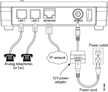
Figure 3-1 Cisco ATA Rear Panel Connections
Network Requirements
The ATA 187 acts as an endpoint on an IP telephony network. The following equipment is required:
•![]() Call Control system
Call Control system
•![]() Voice packet gateway—Required if you are connecting to the Public Switched Telephone Network (PSTN). A gateway is not required if an analog key system is in effect.
Voice packet gateway—Required if you are connecting to the Public Switched Telephone Network (PSTN). A gateway is not required if an analog key system is in effect.
•![]() Ethernet connection
Ethernet connection
Safety Recommendations
To ensure general safety, follow these guidelines:
•![]() Do not get this product wet or pour liquids into this device.
Do not get this product wet or pour liquids into this device.
•![]() Do not open or disassemble this product.
Do not open or disassemble this product.
•![]() Do not perform any action that creates a potential hazard to people or makes the equipment unsafe.
Do not perform any action that creates a potential hazard to people or makes the equipment unsafe.
•![]() Use only the power supply that comes with the ATA 187.
Use only the power supply that comes with the ATA 187.
 |
Warning |
|
Warning |
|
Warning |
|
Warning |
For translated warnings, see the Regulatory Compliance and Safety Information for the Cisco ATA 187 manual.
What the ATA 187 Package Includes
The ATA 187 package contains the following items:
•![]() Cisco ATA 187 Analog Telephone Adaptor
Cisco ATA 187 Analog Telephone Adaptor
•![]() Cisco ATA 187 Analog Telephone Adaptor at a Glance
Cisco ATA 187 Analog Telephone Adaptor at a Glance
•![]() Cisco ATA 187 Analog Telephone Adaptor (SIP) Product Safety and User Manual
Cisco ATA 187 Analog Telephone Adaptor (SIP) Product Safety and User Manual
•![]() Regulatory Compliance and Safety Information for the ATA 187
Regulatory Compliance and Safety Information for the ATA 187
•![]() 12V power adaptor
12V power adaptor
•![]() Power cord
Power cord

Note ![]() The ATA 187 is intended for use only with the 12V DC power adaptor that comes with the unit.
The ATA 187 is intended for use only with the 12V DC power adaptor that comes with the unit.
Installing the ATA 187
To install an ATA 187, follow these steps:
Procedure
Step 1 ![]() Connect the power supply to the Cisco DC Adapter port.
Connect the power supply to the Cisco DC Adapter port.
Step 2 ![]() Connect a straight-through Ethernet cable from the network to the 10/100 SW port on the ATA 187. Each ATA 187 ships with one Ethernet cable in the box.
Connect a straight-through Ethernet cable from the network to the 10/100 SW port on the ATA 187. Each ATA 187 ships with one Ethernet cable in the box.
Note ![]() You can use either Category 3/5/5e/6 cabling for 10 Mbps connections, but you must use Category 5/5e/6 for 100 Mbps connections.
You can use either Category 3/5/5e/6 cabling for 10 Mbps connections, but you must use Category 5/5e/6 for 100 Mbps connections.
Attaching a Phone to the ATA 187
You can attach one or two phones to an ATA 187 by connecting them to a line port of the ATA 187 with a RJ11 cable. The line LED will blink when there is activity on that line.
Verifying the ATA 187 Startup Process
After the ATA 187 has power connected to it, the phone begins its startup process by cycling through these steps:
1. ![]() The LEDs are on.
The LEDs are on.
a. ![]() Power
Power
b. ![]() Line 1
Line 1
c. ![]() Line 2
Line 2
d. ![]() Set Up
Set Up
The ATA 187 boots up in this step; it may take up to one minute.
2. ![]() The LEDs flash.
The LEDs flash.
The ATA 187 is launching its application in this step.
3. ![]() Only the Power LED is on.
Only the Power LED is on.
The ATA 187 is registering with Cisco Unified Communications Manager. You will hear a busy tone when you go offhook on the phone. It can take up to one minute for this to complete.
4. ![]() All of the LEDs flash again (Optional).
All of the LEDs flash again (Optional).
If the ATA 187 flash memory is erased or the load is corrupted, all the LEDs will flash again. The ATA 187 will download the image files and write to the flash. The ATA 187 will reboot and start from step 1.
When you go offhook on the phone, you will see the line LED on and you will hear dial tone. The ATA 187 has completed the startup process.
Configuring Startup Network Settings
If you are not using DHCP in your network, you must configure these network settings on the ATA 187 after installing the device on the network:
•![]() IP subnet information (subnet mask for IPv4)
IP subnet information (subnet mask for IPv4)
•![]() TFTP server IP address
TFTP server IP address
You may also configure these optional settings as necessary:
Administration VLAN ID
Collect this information and see instructions in Chapter "Voice Menu Codes".
Configuring Security on the ATA 187
The security features protect against several threats, including threats to the identity of the phone and to data. These features establish and maintain authenticated communication streams between the phone and the Cisco Unified Communications Manager server, and digitally sign files before they are delivered.
For more information about the security features, see the Cisco Unified Communications Manager Security Guide.
You can initiate the installation of a Locally Significant Certificate (LSC) from the Security Configuration menu on the phone. This menu also lets you update or remove an LSC.
Before you begin, make sure that the appropriate Cisco Unified Communications Manager and the CAPF security configurations are complete:
•![]() On Cisco Unified Communications Operating System Administration, verify that the CAPF certificate has been installed
On Cisco Unified Communications Operating System Administration, verify that the CAPF certificate has been installed
•![]() The CAPF is running and configured
The CAPF is running and configured
See the Cisco Unified Communications Manager Security Guide for more information.
Note ![]() If you want to update LSC, you need to use reset to factory default from Chapter "Voice Menu Codes".
If you want to update LSC, you need to use reset to factory default from Chapter "Voice Menu Codes".
 Feedback