Provisioning Basic SS7 Configurations
This chapter describes the provisioning process for the Cisco ITP, Mated Signal Transfer Point (STP)-Pair configurations, Cisco BTS 10200 Softswitch for Shared Point Code, SCTP provisioning, and NSO configuration and contains the following sections:
•![]() ITP AS and ASP Configuration Example
ITP AS and ASP Configuration Example
•![]() Mated STP-Pair Configuration Example
Mated STP-Pair Configuration Example
•![]() Shared Point Code Configuration Example
Shared Point Code Configuration Example
Each of the configuration examples include Cisco BTS 10200 example provisioning that is related to the associated profile. For a complete description of provisioning SS7 related objects on the Cisco BTS 10200, please refer to the following URL:
http://www.cisco.com/univercd/cc/td/doc/product/voice/bts10200/bts4_1/provgd/41_ss7.htm
The DSCP is now configured in the ca-config table. For information about the SCTP-DSCP token, refer to the Cisco BTS 10200 Softswitch CLI Database.
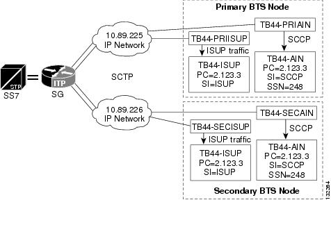
ITP AS and ASP Configuration Example
The IETF SIGTRAN standard defines how a signaling gateway, such as the Cisco ITP, routes traffic from the Signaling System 7 (SS7) service provider towards a SIGTRAN enabled IP endpoint, such as the Cisco BTS 10200 Softswitch. This section provides a basic example and diagram for configuring an application server (AS) and application server process (ASP) on the ITP. Please refer to Figure 2-3 when reading this example.
The following components are configured in this example:
•![]() Routing Key—A set of SS7 parameters, such as Destination Point Code (DPC), Origination Point Code (OPC), SI, Carrier Identification Code (CIC) range, and Subsystem Number (SSN), that uniquely define the range of signaling traffic to be handled by a particular AS.
Routing Key—A set of SS7 parameters, such as Destination Point Code (DPC), Origination Point Code (OPC), SI, Carrier Identification Code (CIC) range, and Subsystem Number (SSN), that uniquely define the range of signaling traffic to be handled by a particular AS.
•![]() Routing Context—A value that uniquely defines a routing key.
Routing Context—A value that uniquely defines a routing key.
•![]() Application Server (AS)—A logical entity serving a specific routing key. An example of an application server is a switch element handling all call processing for a unique range of SS7 network trunks, identified by an SS7 SI, DPC, OPC, Subsystem, and CIC-range. The AS will contain two application server processes, one of which is actively processing traffic. Note that there is a one-to-one relationship between an AS and a routing key.
Application Server (AS)—A logical entity serving a specific routing key. An example of an application server is a switch element handling all call processing for a unique range of SS7 network trunks, identified by an SS7 SI, DPC, OPC, Subsystem, and CIC-range. The AS will contain two application server processes, one of which is actively processing traffic. Note that there is a one-to-one relationship between an AS and a routing key.
•![]() Application Server Process (ASP)—An active or standby process instance of an application server (in the BTS, it is either the active or standby BTS signaling gateway adapter or Transaction Capabilities Application Part [TCAP] signaling adapter software process). An ASP is defined by its Stream Control Transmission Protocol [SCTP] endpoint information (two IP addresses and port) and may be configured to process signaling traffic within more than one application server.
Application Server Process (ASP)—An active or standby process instance of an application server (in the BTS, it is either the active or standby BTS signaling gateway adapter or Transaction Capabilities Application Part [TCAP] signaling adapter software process). An ASP is defined by its Stream Control Transmission Protocol [SCTP] endpoint information (two IP addresses and port) and may be configured to process signaling traffic within more than one application server.
Cisco ITP Configuration
The following ASP configuration defines the primary side TCAP Signaling Adapter (TSA) process on FSAIN. TB44-PRIAIN is the variable name of the ASP, 12205 is the remote (Cisco BTS 10200) port number, 14001 is the local (Cisco ITP) port number, and SUA defines the Layer 3 SIGTRAN protocol that is utilized to transfer information to the ASP. In this definition, there are also the two IP addresses of the Cisco BTS 10200 Softswitch that the TSA process on FSAIN uses for SUA communication.
The following example defines the local port defined for M3UA traffic on ITP:
cs7 m3ua 2905
local-ip 10.89.225.200
local-ip 10.89.226.200
The following defines the local port defined for SUA traffic on ITP:
cs7 sua 14001
local-ip 10.89.225.200
local-ip 10.89.226.200
cs7 asp TB44-PRIAIN 12205 14001 sua
remote-ip 10.89.225.234
remote-ip 10.89.226.234
The following configuration defines information for the secondary side TSA process on FSAIN:
cs7 asp TB44-SECAIN 12205 14001 sua
remote-ip 10.89.225.235
remote-ip 10.89.226.235
The following configuration defines an ASP that uses M3UA to transfer information to
the ASP. This configuration is for the primary side SGA process:
cs7 asp TB44-PRIISUP 11146 2905 m3ua
remote-ip 10.89.225.234
remote-ip 10.89.226.234
The following configuration is for the secondary side SGA process:
cs7 asp TB44-SECISUP 11146 2905 m3ua
remote-ip 10.89.225.235
remote-ip 10.89.226.235
The AS configuration defines the routing key, which defines a filter for the traffic
that will be sent towards the associated ASPs. The filter is based on parameters within
incoming messages from the SS7 network, such as DPC, OPC, CIC range, service
indicator, and SSN:
The following line of the AS configuration defines an AS name of TB44-ISUP and also
says that the AS is defined for M3UA:
cs7 as TB44-ISUP m3ua
The following line defines the routing key. It is identified by a routing context value of 1. It also includes a DPC value of 2.1.3 (which is the BTS OPC). The next parameter in the routing key is the service indicator, SI ISUP. This means that when a Layer 4 SS7 message (such as an ISUP message) is received from the SS7 network, if the DPC in the MTP3 header is 2.1.3 and the SI indicates ISUP, it will be processed by this AS.
routing-key 1 2.1.3 si isup
The following lines of the AS configuration defines the two associated ASPs. These represent the active and standby BTS processes, one of which will actually do the processing:
asp TB44-PRIISUP
asp TB44-SECISUP
The following line of the AS configuration indicates that override mode is being used
for this AS. Either ASP TB44-PRIISUP or ASP TB44-SECISUP will process the traffic (as opposed to a load-share mode, which is not supported):
traffic-mode override
The following AS definition is for processing AIN traffic. Instead of defining M3UA as the SIGTRAN protocol, which is used to communicate with this AS, SUA is the defined protocol. In addition to the DPC and SI definitions in the routing key definition, an SSN value of 248 is also used to further refine the filter.
cs7 as TB44-AIN sua
routing-key 2 2.1.3 si sccp ssn 248
asp TB44-SECAIN
asp TB44-PRIAIN
traffic-mode override
Overlapping AS Configurations
The following AS configuration example is similar to the one in the previous subsection but has more information in the routing key definition.
In the following AS configuration, the routing key has a routing context value of 10. The routing key defined DPC value is 2.1.3. The routing key also defines an OPC value of 3.50.3. This OPC has a mask value of 255.255.255, which means all bits of the OPC will be considered when routing. It defines an SI of ISUP and a CIC range of 1 to 23. Therefore, this AS will route messages towards ASP PRI_ISUP_BTS2 or SEC_ISUP_BTS2, if the message has the following criteria: the DPC is 2.1.3, the OPC is 3.50.3, the service indicator is ISUP, and the CIC range is between 1 and 23.
cs7 as ISUP_BTS1 m3ua
routing-key 10 2.1.3 opc 3.50.3 255.255.255 si isup cic 1 23
asp PRI_ISUP_BTS2
asp SEC_ISUP_BTS2
traffic-mode override
This AS (ISUP_BTS1) and the AS of the previous section (TB44-ISUP) both route ISUP messages from the SS7 network that have DPC values of 2.1.3. The ITP routes towards the ASP that matches best when the DPC in the incoming ISUP message is 2.1.3. ISUP_BTS1 requires that four parameters from the incoming SS7 message match its routing key. TB44-ISUP only requires that two parameters match. If all four parameters of routing-key 10 match, then ISUP_BTS1 will be chosen. If only three parameters of routing-key 10 match, then routing key 1 is a better match, and TB44-ISUP will be chosen to process the message.
GTT Configuration
When an ITP pair is connected to a service provider's network using a Mated STP-Pair configuration, the ITP pair can be used as an STP pair. In this case, GTT can be performed on the ITP. The GTT table needs to be populated for remote subsystems and preserved as part of the start-up configuration. For additional information on populating the ITP GTT table.
Extra steps are needed to save it in the flash and have the startup procedure load it from the flash. The following is an example procedure:
Step 1 ![]() On ITP1, add the GTT entry in the global config mode:
On ITP1, add the GTT entry in the global config mode:
cs7 gtt selector acar_sel
gta 469255 pcssn 1.1.30 pcssn ssn 251
gta 469256 pcssn 1.1.31 pcssn ssn 251
Step 2 ![]() On ITP1, save the GTT table in the privileged enable mode:
On ITP1, save the GTT table in the privileged enable mode:
cs7 save gtt-table flash:gttdata.txt
Step 3 ![]() On ITP1, save the configuration:
On ITP1, save the configuration:
copy run start
Step 4 ![]() Swap the flash card between ITP1 and ITP2.
Swap the flash card between ITP1 and ITP2.
Step 5 ![]() On ITP2, load the GTT table in the global config mode:
On ITP2, load the GTT table in the global config mode:
cs7 gtt load flash:gttdata.txt
Step 6 ![]() Swap the flash card between ITP1 and ITP2.
Swap the flash card between ITP1 and ITP2.
Step 7 ![]() On ITP2, save the GTT table in the privileged enable mode:
On ITP2, save the GTT table in the privileged enable mode:
cs7 save gtt-table flash:gttdata.txt
Step 8 ![]() On ITP2, save the configuration:
On ITP2, save the configuration:
copy run start
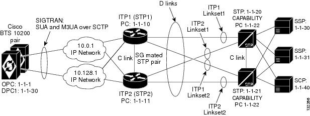
Mated STP-Pair Configuration Example
A Mated STP-Pair configuration is used to access the SS7 service provider network STP, usually using SS7 D-links, although A-links can also be used to connect to an SEP in the network. With a Mated STP-Pair configuration, ITPs support GTT, and geographical separation is available.
This section provides an example and diagram for a basic Mated STP-Pair configuration. Please refer to Figure 2-1 when reading this example.

Note ![]() The ITP configuration may vary slightly depending on the ITP platform.
The ITP configuration may vary slightly depending on the ITP platform.
Figure 2-1 Mated STP-Pair Configuration
Cisco ITP Configuration
ITP1 Configuration
ITP1 is the first ITP in the sg-pair (each ITP in the sg-pair functions as an STP).
Current configuration : 3470 bytes
!
version 12.2
service timestamps debug datetime msec
service timestamps log datetime msec
no service password-encryption
!
hostname ITP1
!
boot-start-marker
boot system flash c2600-itp-mz.topsail_s_nightly_040915
boot-end-marker
!
redundancy inter-device
!
enable secret 5 $1$XCoU$j0Y2wFRoks2pocHa1gHhi0
enable password cisco
!
memory-size iomem 20
ip subnet-zero
!
ip domain-name cisco.com
ip name-server 10.0.0.6
For the Mated STP-Pair configuration (SG Mated Pair), the local point code value is 1.1.10, which is different than the BTS OPC and the other ITP (ITP1) that makes up the SG Mated Pair.
cs7 variant ANSI
cs7 point-code 1.1.10
!
controller E1 0/0
framing NO-CRC4
channel-group 0 timeslots 1
!
controller E1 0/1
framing NO-CRC4
channel-group 0 timeslots 1
!
controller E1 0/2
shutdown
!
controller E1 0/3
shutdown
!
interface Serial0/0:0
description connect to link 0 of STP 1-1-20
no ip address
encapsulation mtp2
no clns route-cache
!
interface Serial0/1:0
description connect to link 0 of STP 1-1-21
no ip address
encapsulation mtp2
no clns route-cache
interface FastEthernet0/0
ip address 10.0.1.54 255.255.0.0
speed auto
half-duplex
no clns route-cache
!
interface FastEthernet0/1
ip address 10.128.1.239 255.255.0.0
speed auto
half-duplex
no clns route-cache
In the Mated STP-Pair configuration, instead of defining a cs7 group, as is done in the Shared Point Code configuration, a "local-peer" and "mated-sg" are defined. Here, we define the local-peer, which is the local definition for the C-link connection between the two ITPs that make up the redundant STP pair.
cs7 local-peer 7000
local-ip 10.0.1.54
local-ip 10.128.1.239
Linkset definitions—The number after 'link' represents SLC.
cs7 linkset lset1chn 1.1.20
link 0 Serial0/0:0
!
cs7 linkset lset2chn 1.1.21
link 0 Serial0/1:0
C-link linkset definition—Here the point code value and IP information for the mated-sg is defined. The local IP information is defined in the local-peer definition above.
cs7 linkset c-link 1.1.11
link 0 sctp 10.0.1.55 10.128.1.240 7000 7000
SS7 Route Definitions
In the following entries, note the following:
•![]() All of the routes towards all DPCs are configured with equal priority when using lset1chn or lset2chn.
All of the routes towards all DPCs are configured with equal priority when using lset1chn or lset2chn.
•![]() There are lower priority routes towards each destination across the c-link.
There are lower priority routes towards each destination across the c-link.
•![]() Routing towards the capability PC of the adjacent STPs is treated as if the capability PC is a DPC beyond the STP.
Routing towards the capability PC of the adjacent STPs is treated as if the capability PC is a DPC beyond the STP.
cs7 route-table system
update route 1.1.30 255.255.255 linkset lset1chn priority 1
update route 1.1.30 255.255.255 linkset lset2chn priority 1
update route 1.1.31 255.255.255 linkset lset1chn priority 1
update route 1.1.31 255.255.255 linkset lset2chn priority 1
update route 1.1.40 255.255.255 linkset lset2chn priority 1
update route 1.1.40 255.255.255 linkset lset1chn priority 1
Lower priority C-link routes
update route 1.1.30 255.255.255 linkset c-link priority 2
update route 1.1.31 255.255.255 linkset c-link priority 2
update route 1.1.40 255.255.255 linkset c-link priority 2
Routing to capability point codes of adjacent STPs
update route 1.1.22 255.255.255 linkset lset1chn priority 1
update route 1.1.22 255.255.255 linkset lset2chn priority 1
With the mated-sg (Mated STP-Pair configuration), you must also define a connection between the ITPs to pass SIGTRAN specific state information and other data. This is done by defining the local IP information in the "cs7 sgmp" configuration and the peer IP information in the "cs7 mated-sg" configuration.
cs7 sgmp 9101
local-ip 10.0.1.54
local-ip 10.128.1.239
!
cs7 mated-sg ITP2 9101
remote-ip 10.0.1.55
remote-ip 10.128.1.240
The M3UA definition that declares local IP addresses and port number
cs7 m3ua 2905
local-ip 10.0.1.54
local-ip 10.128.1.239
keepalive 2000
Here, as with all configurations, there are a minimum of two ASPs defined for each AS, one for the primary BTS node and one for the Secondary. In reality, there will be at least one for each user part on the Cisco BTS 10200, so if you have a TCAP service going over SUA and ISUP traffic, you will have a total of at least four ASPs: primary ISUP, secondary ISUP, primary TCAP service, and secondary TCAP service. 2905 is the local port value. The remote IP addresses are the BTS IP addresses. They are also obtained through the fully-qualified domain name (FQDN) that is an SGA command line argument.
cs7 asp PriCaIsupAsp 11146 2905 m3ua
remote-ip 10.0.1.5
remote-ip 10.128.1.2
!
cs7 asp SecCaIsupAsp 11146 2905 m3ua
remote-ip 10.0.1.6
remote-ip 10.128.1.3
The routing key is a very simple one. It has a routing context of 1 defined, the DPC (BTS OPC) of 1.1.1 defined, and a service indicator of ISUP defined. This means that all traffic coming from the SS7 service provider network that has a DPC of 1.1.1 and a service indicator of ISUP will be sent to either PrimaryBtsIsupAsp or SecondaryBtsIsupAsp (depending on which one is active). The traffic mode is always set to override (not loadshare), as with the current implementation, only the override application server traffic mode is supported. In the case of override-traffic mode, the reception of ASP active messages at the SGP causes the redirection of all traffic for the AS to the ASP that sent the ASP active message.
The SUA definition that declares local IP addresses and port number
cs7 sua 14001
local-ip 10.0.1.54
local-ip 10.128.1.239
keepalive 2000
Here we are defining an ASP that will process AIN related traffic.
cs7 asp PrimFsAinAsp 12205 14001 sua
remote-ip 10.0.1.5
remote-ip 10.128.1.2
!
cs7 asp SecFsAinAsp 12205 14001 sua
remote-ip 10.0.1.6
remote-ip 10.128.1.3
!
cs7 asp PriFsPtcAsp 12235 14001 sua
remote-ip 10.0.1.5
remote-ip 10.128.1.2
!
cs7 asp SecFsPtcAsp 12235 14001 sua
remote-ip 10.0.1.6
remote-ip 10.128.1.3
The following AS is defined for LNP related message flows. The routing context value is 4, the DPC (BTS OPC) is 1.1.1, the service indicator is SCCP and the subsystem number is 247. This means that any message received from the SS7 service provider that has a DPC of 1.1.1, a service indicator of SCCP and an SSN of 247 will be sent to either PrimaryBtsAinAsp or SecondaryBtsAinAsp (depending on which one is active).
cs7 as FsAinLnpAs sua
routing-key 4402 1.1.1 si sccp ssn 247
asp PriFsAinAsp
asp SecFsAinAsp
traffic-mode override
!
cs7 as FsAin800TAs sua
routing-key 4404 1.1.1 si sccp ssn 254
asp PriFsAinAsp
asp SecFsAinAsp
traffic-mode override
!
cs7 as FsAin800AAs sua
routing-key 4403 1.1.1 si sccp ssn 248
asp PriFsAinAsp
asp SecFsAinAsp
traffic-mode override
!
cs7 as FsPtcCnamAs sua
routing-key 4404 1.1.1 si sccp ssn 232
asp PriFsPtcAsp
asp SecFsPtcAsp
traffic-mode override
!
cs7 as FsPtcAcarAs sua
routing-key 4405 1.1.1 si sccp ssn 251
asp PriFsPtcAsp
asp SecFsPtcAsp
traffic-mode override
!
cs7 gtt load flash:gttdata.txt
!
ITP2 Configuration
ITP2 is the second ITP in the sg-pair (each ITP in the sg-pair functions as an STP).
Current configuration : 4054 bytes
!
version 12.2
service timestamps debug datetime msec
service timestamps log datetime msec
no service password-encryption
!
hostname ITP2
!
boot-start-marker
boot system flash 2600/c2600-itp-mz.topsail_s_nightly_040915
boot-end-marker
!
redundancy inter-device
!
enable secret 5 $1$B6u2$gI4fFgjOQo5XppDSWJDfI.
enable password cisco
!
!
memory-size iomem 10
ip subnet-zero
!
ip domain-name cisco.com
ip name-server 10.0.0.6
!
cs7 variant ANSI
For the Mated STP-Pair configuration (SG Mated Pair) configuration, the local point code value is 1.1.11, which is different than the BTS OPC and the other ITP (ITP1) that makes up the SG Mated Pair.
cs7 point-code 1.1.11
!
controller E1 0/0
framing NO-CRC4
channel-group 0 timeslots 1
!
controller E1 0/1
framing NO-CRC4
channel-group 0 timeslots 1
!
controller E1 0/2
shutdown
!
controller E1 0/3
shutdown
!
interface FastEthernet0/0
ip address 10.0.1.55 255.255.0.0
speed auto
half-duplex
no clns route-cache
!
interface FastEthernet0/1
ip address 10.128.1.240 255.255.0.0
speed auto
half-duplex
no clns route-cache
!
interface Serial0/0:0
description connect to link 1 of STP 1-1-20
no ip address
encapsulation mtp2
no clns route-cache
interface Serial0/1:0
description connect to link 1 of STP 1-1-21
no ip address
encapsulation mtp2
no clns route-cache
local-peer definition
cs7 local-peer 7000
local-ip 10.0.1.55
local-ip 10.128.1.240
Linkset definitions—The number after 'link' represents SLC.
cs7 linkset lset1chn 1.1.20
link 1 Serial0/0:0
!
cs7 linkset lset2chn 1.1.21
link 1 Serial0/1:0
C-link linkset definition
cs7 linkset c-link 1.1.10
link 0 sctp 10.0.1.54 10.128.1.239 7000 7000
!
cs7 route-table system
update route 1.1.30 255.255.255 linkset lset1chn priority 1
update route 1.1.30 255.255.255 linkset lset2chn priority 1
update route 1.1.31 255.255.255 linkset lset1chn priority 1
update route 1.1.31 255.255.255 linkset lset2chn priority 1
update route 1.1.40 255.255.255 linkset lset2chn priority 1
update route 1.1.40 255.255.255 linkset lset1chn priority 1
C-link routes
update route 1.1.30 255.255.255 linkset c-link priority 2
update route 1.1.31 255.255.255 linkset c-link priority 2
update route 1.1.40 255.255.255 linkset c-link priority 2
Routing to capability point codes of adjacent STPs
update route 1.1.22 255.255.255 linkset lset1chn priority 1
update route 1.1.22 255.255.255 linkset lset2chn priority 1
!
cs7 sgmp 9101
local-ip 10.0.1.55
local-ip 10.128.1.240
!
cs7 mated-sg ITP1 9101
remote-ip 10.0.1.54
remote-ip 10.128.1.239
cs7 m3ua 2905
local-ip 10.0.1.55
local-ip 10.128.1.240
!
cs7 asp PriCaIsupAsp 11146 2905 m3ua
remote-ip 10.0.1.5
remote-ip 10.128.1.2
!
cs7 asp SecCaIsupAsp 11146 2905 m3ua
remote-ip 10.0.1.6
remote-ip 10.128.1.3
!
cs7 as CaIsupAs m3ua
routing-key 1 1.1.1 si isup
asp PriCaIsupAsp
asp SecCaIsupAsp
traffic-mode override
!
cs7 sua 14001
local-ip 10.0.1.55
local-ip 10.128.1.240
keepalive 2000
!
cs7 asp PriFsAinAsp 12205 14001 sua
remote-ip 10.0.1.5
remote-ip 10.128.1.2
!
cs7 asp SecFsAinAsp 12205 14001 sua
remote-ip 10.0.1.6
remote-ip 10.128.1.3
!
cs7 asp PriFsPtcAsp 12235 14001 sua
remote-ip 10.0.1.5
remote-ip 10.128.1.2
!
cs7 asp SecFsPtcAsp 12235 14001 sua
remote-ip 10.0.1.6
remote-ip 10.128.1.3
!
cs7 as FsAinLnpAs sua
routing-key 4402 1.1.1 si sccp ssn 247
asp PriFsAinAsp
asp SecFsAinAsp
traffic-mode override
!
cs7 as FsAin800TAs sua
routing-key 4401 1.1.1 si sccp ssn 254
asp PriFsAinAsp
asp SecFsAinAsp
traffic-mode override
!
cs7 as FsAin800AAs sua
routing-key 4403 1.1.1 si sccp ssn 248
asp PriFsAinAsp
asp SecFsAinAsp
traffic-mode override
!
cs7 as FsPtcCnamAs sua
routing-key 4404 1.1.1 si sccp ssn 232
asp PriFsPtcAsp
asp SecFsPtcAsp
traffic-mode override
!
cs7 as FsPtcAcarAs sua
routing-key 4405 1.1.1 si sccp ssn 251
asp PriFsPtcAsp
asp SecFsPtcAsp
traffic-mode override
!
cs7 gtt load flash:gttdata.txt
!
Cisco BTS 10200 Provisioning for a Mated STP-Pair Configuration
The local IP addresses and port are determined by command line arguments that are passed to the SGA process and TSA processes when they start up. An example SGA command line is:
Args=-t 1 -h crit-aSYS11CA.ipclab.cisco.com -p 11146 -mdldir ../mdl -mdltracedir
../mdltrace -mdltestmode 0 -mdlloadmdo 0 -mdltriggertimer 200 -mdlgarbagetimer 5146
-resetcics 1 -fcmtimer 900 -fcmparalleljobs 4
In this list of arguments, the -h argument, crit-aSYS11CA.ipclab.cisco.com, is a fully qualified domain name (FQDN) that resolves to two local IP addresses. In most cases, the FQDN can be viewed in the /etc/hosts file. To determine the IP addresses to which the FQDN resolves, type nslookup <FQDN>.
The following example configures the Cisco BTS 10200 in the Mated STP-Pair Configuration.
CA Configuration
add ca-config type=MGCP-INIT-TERMS;value=160;datatype=integer;
add ca-config type=MGCP-INIT-DURATION;value=5;datatype=integer;
add ca-config type=MGCP-ICMP-PING-RETRANSMIT-DURATION;value=5;datatype=integer;
add ca-config type=MGCP-ICMP-PING-RETRY-COUNT;value=5;datatype=integer;
add ca-config type=MGCP-MAX-UNREACH-COUNT;value=5;datatype=integer;
add ca-config type=MGCP-MAX-FAULT-COUNT;value=5;datatype=integer;
add ca-config type=MGCP-ADM-RESP-TIME;value=300;datatype=integer;
add ca-config type=MGCP-SIG-TOS-LOWDELAY;value=Y;datatype=boolean;
add ca-config type=MGCP-SIG-TOS-PRECEDENCE;value=1;datatype=integer;
add ca-config type=MGCP-SIG-TOS-RELIABILITY;value=Y;datatype=boolean;
add ca-config type=MGCP-SIG-TOS-THROUGHPUT;value=Y;datatype=boolean;
CA & FS
add call-agent id=CA146; tsap-addr-sidea=hrn11ca; mgw-monitoring-enabled=N;
add feature-server id=FSAIN205; tsap-addr-sidea=hrn11ca:11205; type=AIN;
add feature-server id=FSPTC235; tsap-addr-sidea=hrn11ca:11235; type=PTC;
SIGTRAN components
add user-part-variant id=ANSISS7_GR317;
For the Mated STP-Pair configuration, there are two SGs defined for redundancy. They are essentially mated STPs. This is different than the A, F, or E link configurations, which derive redundancy at the SGP level.
add sg id=sg1; description=Signaling gateway 1;
add sg id=sg2; description=Signaling gateway 2;
In the Mated STP-Pair configuration, the SG-GRP has two SGs defined in the SG-GRP. The A,F, and E link configurations must only have one SG defined in an SG-GRP.
add sg-grp id=sg-grp1; sg1-id=sg1; sg2-id=sg2 description=SG group 1;
In the Mated STP-Pair configuration, there is only one SGP per SG. Note that the two SGPs defined here have a one-to-one correspondence to the SGs that were defined above. This is in contrast to the A,F, and E link configurations, which must have two SGPs per SG.
add sgp id=sg1-sgp1 ; sg-id=sg1; description=SG process 1 for sg1;
add sgp id=sg2-sgp1 ; sg-id=sg2; description=SG process 1 for sg2;
add opc id=opc1; point-code=1-1-1; description=OPC; point-code-type=ANSI_CHINA;
add dpc id=dpc1; point-code=1-1-30; description=DPC 1; point-code-type=ANSI_CHINA;
add dpc id=dpc2; point-code=1-1-31; description=DPC 2; point-code-type=ANSI_CHINA;
ISUP routing keys
add routing-key id=rk1; opc-id=opc1; sg-grp-id=sg-grp1; si=ISUP; rc=1; platform-id=CA146;
add call-ctrl-route id=dpc1-route1; dpc-id=dpc1; routing-key-id=rk1; si=isup;
user-part-variant-id= ANSISS7_GR317
add call-ctrl-route id=dpc2-route1; dpc-id=dpc2; routing-key-id=rk1; si=isup;
user-part-variant-id= ANSISS7_GR317;
add sctp-assoc-profile id=sctp-prof;
SCTP associations—The chosen id name in this statement reflects the fact that this is the SCTP association for SGP1 of SG1.
add sctp-assoc id=sg1-sgp1-sctp; sgp-id=sg1-sgp1; sctp-assoc-profile-id=sctp-prof;
platform-id=CA146; remote-port=2905; remote-tsap-addr1=10.0.1.54;
remote-tsap-addr2=10.128.1.239; ip-tos-precedence=ROUTINE;
add sctp-assoc id=sg2-sgp1-sctp; sgp-id=sg2-sgp1; sctp-assoc-profile-id=sctp-prof;
platform-id=CA146; remote-port=2905; remote-tsap-addr1=10.0.1.55;
remote-tsap-addr2=10.128.1.240; dip-tos-precedence=ROUTINE;
Dial plan profile
add digman-profile id=pretrans;
add digman id=pretrans; rule=1; match-string=^*; replace-string=&; match-noa=any;
replace-noa=VSC;
add digman id=pretrans; rule=2; match-string=^#; replace-string=&; match-noa=any;
replace-noa=VSC;
add digman-profile id=ani_20;
add digman id=ani_20; rule=1; match-string=^20; replace-string=none;
add dial-plan-profile id=dp-1; nanp-dial-plan=Y; description=NA dial plan profile;
dnis-digman-id=pretrans; ani-digman-id=ani_20;
SS7 TG
add ss7-ansi-tg-profile ID=ansi-tg-prof;
add trunk-grp ID=1; call_agent_id=CA146; tg_type=SS7; direction=BOTH;
tg_profile_id=ansi-tg-prof; call-ctrl-route-id=dpc1-route1; dial-plan-id=dp-1;
description=TG to DPC 1;  MGCP_PKG_TYPE=T;
add trunk-grp ID=2; call_agent_id=CA146; tg_type=SS7; direction=BOTH;
tg_profile_id=ansi-tg-prof; call-ctrl-route-id=dpc2-route1; dial-plan-id=dp-1;
description=TG to DPC 2;  MGCP_PKG_TYPE=T;
MGW
add mgw-profile id=as5300-prof; vendor=Cisco; mgcp-hairpin-supp=n; MGCP_RSIPSTAR_SUPP=N;
MGCP_TERM_INIT_LEVEL=0; RBK_ON_CONN_SUPP=N; MGCP_VERSION=MGCP_1_0; mgcp-max2-retries=3;
fax-t38-camode-supp=Y; mgcp-keepalive-interval=60; mgcp-keepalive-retries=10;
mgcp-t-tran=400; mgcp-max1-retries=2; mgcp-t-longtran=5; mgcp-default-pkg=NONE;
MGCP_3WAY_HSHAKE_SUPP=N; mgw_type=AS5300; PC_MPTIME_SUPP=N;
MGCP_VERSION=MGCP_1_0; PC_MPTIME_SUPP=N;
add mgw id=va-5350-23; tsap-addr=va-5350-23.hrndevtest.cisco.com; call-agent-id=CA146;
mgw-profile-id=as5300-prof; type=TGW;
SS7 terminations and trunks
add termination prefix=S3/DS1-4/; port-start=1; port-end=31; type=trunk;
mgw-id=va-5350-23;
add termination prefix=S3/DS1-5/; port-start=1; port-end=31; type=trunk;
mgw-id=va-5350-23;
add trunk cic-start=1; cic-end=31; tgn-id=1; mgw-id=va-5350-23;
termination-prefix=S3/DS1-4/; termination-port-start=1; termination-port-end=31;
add trunk cic-start=1; cic-end=31; tgn-id=2; mgw-id=va-5350-23;
termination-prefix=S3/DS1-5/; termination-port-start=1; termination-port-end=31;
SS7 routes, route guides and destinations
add route id=dpc1-route; tg_selection=RR; tgn1_id=1;
add route id=dpc2-route; tg_selection=RR; tgn1_id=2;
add route-guide id=dpc1-rg; policy-type=ROUTE; policy-id=dpc1-route;
add route-guide id=dpc2-rg; policy-type=ROUTE; policy-id=dpc2-route;
add destination dest-id=dpc1-dest; call-type=LOCAL; route-type=ROUTE;
route-guide-id=dpc1-rg;
add destination dest-id=dpc2-dest; call-type=LOCAL; route-type=ROUTE;
route-guide-id=dpc2-rg;
TCAP/SUA provisioning for FSAIN, FSPTC
add sctp-assoc id=sg1-sgp1-sctp-ain; sgp-id=sg1-sgp1; sctp-assoc-profile-id=sctp-prof;
platform-id=FSAIN205; remote-port=14001; remote-tsap-addr1=10.0.1.54;
remote-tsap-addr2=10.128.1.239; ip-tos-precedence=ROUTINE;
add sctp-assoc id=sg2-sgp1-sctp-ain; sgp-id=sg2-sgp1; sctp-assoc-profile-id=sctp-prof;
platform-id=FSAIN205; remote-port=14001; remote-tsap-addr1=10.0.1.55;
remote-tsap-addr2=10.128.1.240; ip-tos-precedence=ROUTINE;
add sctp-assoc id=sg1-sgp1-sctp-ptc; sgp-id=sg1-sgp1; sctp-assoc-profile-id=sctp-prof;
platform-id=FSPTC235; remote-port=14001; remote-tsap-addr1=10.0.1.54;
remote-tsap-addr2=10.128.1.239; ip-tos-precedence=ROUTINE;
add sctp-assoc id=sg2-sgp1-sctp-ptc; sgp-id=sg2-sgp1; sctp-assoc-profile-id=sctp-prof;
platform-id=FSPTC235; remote-port=14001; remote-tsap-addr1=10.0.1.55;
remote-tsap-addr2=10.128.1.240; ip-tos-precedence=ROUTINE;
add sccp-nw id=1;NET_IND=NATIONAL;SUB_SVC=NATIONAL;HOP_COUNT=3;
add subsystem-profile id=SS_LNP; platform-id=FSAIN205; description=LNP subsystem;
add subsystem-profile id=SS_800A; platform-id=FSAIN205; description=AIN 800 subsystem;
add subsystem-profile id=SS_800T; platform-id=FSAIN205; description=IN1 800 subsystem;
add subsystem-profile id=SS_CNAM; platform-id=FSAIN205; description=CNAM subsystem;
add subsystem-profile id=SS_ACAR; platform-id=FSPTC235; description=ACAR subsystem;
add subsystem id=SS_LNP;  opc-id=opc1; local-ssn=247; remote-ssn=247; sccp-nw-id=1;
SCCP_VERSION=ANS92; TCAP_VERSION=ANS92; APPLICATION_VERSION=AIN01;
add subsystem id=SS_800A; opc-id=opc1; local-ssn=248; remote-ssn=248; sccp-nw-id=1;
SCCP_VERSION=ANS92; TCAP_VERSION=ANS92; APPLICATION_VERSION=AIN01;
add subsystem id=SS_CNAM; opc-id=opc1; local-ssn=232; remote-ssn=232; sccp-nw-id=1;
SCCP_VERSION=ANS92; TCAP_VERSION=ANS92; APPLICATION_VERSION=IN1;
add subsystem id=SS_800T; opc-id=opc1; local-ssn=254; remote-ssn=254; sccp-nw-id=1;
SCCP_VERSION=ANS92; TCAP_VERSION=ANS92; APPLICATION_VERSION=IN1;
add subsystem id=SS_ACAR; opc-id=opc1; local-ssn=251; remote-ssn=251; sccp-nw-id=1;
SCCP_VERSION=ANS92; TCAP_VERSION=ANS92; APPLICATION_VERSION=IN1;
add routing-key id=rk_lnp;  opc-id=opc1; sg-grp-id=sg_grp1; si=SCCP; rc=4402;
PLATFORM_ID=FSAIN205; ssn-id=SS_LNP;
add routing-key id=rk_800a; opc-id=opc1; sg-grp-id=sg_grp1; si=SCCP; rc=4403;
PLATFORM_ID=FSAIN205; ssn-id=SS_800A;
add routing-key id=rk_cnam; opc-id=opc1; sg-grp-id=sg_grp1; si=SCCP; rc=4404;
PLATFORM_ID=FSAIN205; ssn-id=SS_CNAM;
add routing-key id=rk_800t; opc-id=opc1; sg-grp-id=sg_grp1; si=SCCP; rc=4401;
PLATFORM_ID=FSAIN205; ssn-id=SS_800T;
add routing-key id=rk_acar; opc-id=opc1; sg-grp-id=sg_grp1; si=SCCP; rc=4405;
PLATFORM_ID=FSPTC235; ssn-id=SS_ACAR;
Provisioned DPC is the STP capability point code
add dpc id=stp_cap_pc; point-code=1-1-22; point-code-type=ANSI_CHINA;
description=Capability Point Code of STPs
add feature fname=LNP; feature-server-id=FSAIN205; description=Local number portability;
tdp1=COLLECTED_INFORMATION; tid1=LNP_TRIGGER; ttype1=R;
add ported-office-code digit-string=301-612; in-call-agent=n;
add CA-Config type=DEFAULT-LNP-SLHR-ID; datatype=string; value=slhr_lnp;
add slhr-profile id=slhr_800t; description=Service Logic Host Routing Table for IN1 800
Service;
add slhr-profile id=slhr_lnp;  description=Service Logic Host Routing Table for AIN LNP
Service;
add slhr-profile id=slhr_800a; description=Service Logic Host Routing Table for AIN 800
Service;
add slhr-profile id=slhr_cnam; description=Service Logic Host Routing Table for IN1 CNAM
Service;
add slhr-profile id=slhr_acar; description=Service Logic Host Routing Table for ACAR
Service;
add slhr id=slhr_800t; opc-id=opc1; dpc-id=stp_cap_pc; ssn-id=SS_800T; gtt-req=Y; tt=254;
GTT_ADDR_TYPE=CDPN; GTT_ADDR=3;
add slhr id=slhr_lnp;  opc-id=opc1; dpc-id=stp_cap_pc; ssn-id=SS_LNP;  gtt-req=Y; tt=11;
GTT_ADDR_TYPE=CDPN; GTT_ADDR=3;
add slhr id=slhr_800a; opc-id=opc1; dpc-id=stp_cap_pc; ssn-id=SS_800A; gtt-req=Y; tt=8;
GTT_ADDR_TYPE=CDPN; GTT_ADDR=3;
add slhr id=slhr_cnam; opc-id=opc1; dpc-id=stp_cap_pc; ssn-id=SS_CNAM; gtt-req=Y; tt=5;
GTT_ADDR_TYPE=CLGN; GTT_ADDR=3;
add slhr id=slhr_acar; opc-id=opc1; dpc-id=stp_cap_pc; ssn-id=SS_ACAR; gtt-req=Y; tt=251;
GTT_ADDR_TYPE=CDPN; GTT_ADDR=10;
add sccp-route opc-id=opc1; dpc-id=stp_cap_pc; ssn-id=SS_800T; rk-id=rk_800t;
add sccp-route opc-id=opc1; dpc-id=stp_cap_pc; ssn-id=SS_800A; rk-id=rk_800a;
add sccp-route opc-id=opc1; dpc-id=stp_cap_pc; ssn-id=SS_LNP; rk-id=rk_lnp;
add sccp-route opc-id=opc1; dpc-id=stp_cap_pc; ssn-id=SS_CNAM; rk-id=rk_cnam;
add sccp-route opc-id=opc1; dpc-id=stp_cap_pc; ssn-id=SS_ACAR; rk-id=rk_acar;
add sccp-route SSN_ID=SS_ACAR; OPC_ID=opc1; DPC_ID=dpc1; RK_ID=rk_acar
add sccp-route SSN_ID=SS_ACAR; OPC_ID=opc1; DPC_ID=dpc2; RK_ID=rk_acar
add pop ID=50901; STATE=tx; COUNTRY=US; TIMEZONE=CDT; LOCAL_7D_DIALING=Y; ITP=N;
ZERO_MINUS=LEC; BLOCK_EAWOPIC=Y; CNAM_OPTION=EXT_LIDB; PIC2_REQD=N; MY_LRN=4692559999;
TREAT_IMS_ANONYMOUS=N; OPC_ID=opc1; ZERO_PLUS_LOCAL=N
Control network entities in-service for ANSI SS7
control trunk-grp id=1; mode=forced; target-state=ins;
control trunk-grp id=2; mode=forced; target-state=ins;
equip trunk-termination tgn-id=1; cic=all;
equip trunk-termination tgn-id=2; cic=all;
control trunk-termination tgn-id=1; cic=all; target-state=INS; mode=FORCED;
control trunk-termination tgn-id=2; cic=all; target-state=INS; mode=FORCED;
control sctp-assoc id=sg1-sgp1-sctp; mode=forced; target-state=INS;
control sctp-assoc id=sg2-sgp1-sctp; mode=forced; target-state=INS;
control sctp-assoc id=sg1-sgp1-sctp-ain; mode=forced; target-state=INS;
control sctp-assoc id=sg2-sgp1-sctp-ain; mode=forced; target-state=INS;
control sctp-assoc id=sg1-sgp1-sctp-ptc; mode=forced; target-state=INS;
control sctp-assoc id=sg2-sgp1-sctp-ptc; mode=forced; target-state=INS;
control subsystem id=SS_800T; opc-id=opc; target-state=UIS; mode=FORCED;
control subsystem id=SS_LNP; opc-id=opc; target-state=UIS; mode=FORCED;
control subsystem id=SS_800A; opc-id=opc; target-state=UIS; mode=FORCED;
control subsystem id=SS_CNAM; opc-id=opc; target-state=UIS; mode=FORCED;
control subsystem id=SS_ACAR; opc-id=opc; target-state=UIS; mode=FORCED;
Status commands
# status trunk-grp id=1;
# status trunk-grp id=2;
# status trunk-termination tgn-id=1; cic=all;
# status trunk-termination tgn-id=2; cic=all;
# status sctp-assoc id=sg1-sgp1-sctp;
# status sctp-assoc id=sg2-sgp1-sctp;
# status sctp-assoc id=sg1-sgp1-sctp-ain;
# status sctp-assoc id=sg2-sgp1-sctp-ain;
# status sctp-assoc id=sg1-sgp1-sctp-ptc;
# status sctp-assoc id=sg2-sgp1-sctp-ptc;
# status subsystem id=SS_800T; opc-id=opc;
# status subsystem id=SS_LNP; opc-id=opc;
# status subsystem id=SS_800A; opc-id=opc;
# status subsystem id=SS_CNAM; opc-id=opc;
# status subsystem id=SS_ACAR; opc-id=opc;
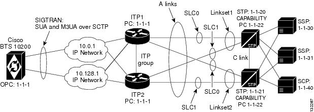
Shared Point Code Configuration Example
A basic Shared Point Code configuration is used when a customer wants an OPC of the BTS to be shared with a point code of the ITP. This usually occurs when the customer wants to access the SS7 service provider network using A-links. It provides a low cost yet fully hardware and network redundant solution. Cost reduction is accomplished by minimizing the number of point codes that are connected to the SS7 service provider network and by connecting via A-links rather than D-links, which require more setup and maintenance.
This section provides an example and diagram for the basic Shared Point Code configuration. Please refer to Figure 2-2 when reading this example.
Note ![]() The ITP configuration may vary slightly, depending on the ITP platform.
The ITP configuration may vary slightly, depending on the ITP platform.
Figure 2-2 Shared Point Code Configuration
ITP Configuration
This section contains a configuration example for the basic Shared Point Code profile. For additional ITP configuration information, please refer to the Cisco IP Transfer Point (ITP) Configuration Guide
Note ![]() When debugging the ITP, the version of the ITP should be noted so the associated ITP manual can be consulted.
When debugging the ITP, the version of the ITP should be noted so the associated ITP manual can be consulted.
ITP1 Configuration
This is the first ITP in the ITP group (the first SGP in the SG).
!
Current configuration : 3470 bytes
!
version 12.2
service timestamps debug datetime msec
service timestamps log datetime msec
no service password-encryption
!
hostname ITP1
!
boot-start-marker
boot system flash c2600-itp-mz.topsail_s_nightly_040915
boot-end-marker
!
redundancy inter-device
!
enable secret 5 $1$XCoU$j0Y2wFRoks2pocHa1gHhi0
enable password cisco
For the Shared Point Code configuration, ipc zone is provisioned to support the link between two ITPs in the ITP-group.
ipc zone default
association 1
no shutdown
protocol sctp
local-port 9001
local-ip 10.0.1.54
local-ip 10.128.1.239
remote-port 9000
remote-ip 10.0.1.55
remote-ip 10.128.1.240
!
memory-size iomem 20
ip subnet-zero
!
ip domain-name cisco.com
ip name-server 10.0.0.6
!
For the Shared Point Code (ITP-group/Distributed MTP) configuration, the local point code value is 1.1.1, which is the same as the BTS OPC.
cs7 variant ANSI
cs7 point-code 1.1.1
!
controller E1 0/0
framing NO-CRC4
channel-group 0 timeslots 1
!
controller E1 0/1
framing NO-CRC4
channel-group 0 timeslots 1
!
controller E1 0/2
shutdown
!
controller E1 0/3
shutdown
!
interface FastEthernet0/0
ip address 10.0.1.54 255.255.0.0
speed auto
half-duplex
no clns route-cache
!
interface Serial0/0:0
description connect to link 0 of STP 1-1-20
no ip address
encapsulation mtp2
no clns route-cache
!
interface FastEthernet0/1
ip address 10.128.1.239 255.255.0.0
speed auto
half-duplex
no clns route-cache
!
interface Serial0/1:0
description connect to link 0 of STP 1-1-21
no ip address
encapsulation mtp2
no clns route-cache
!
Unlike the Mated STP-Pair configuration, which defines a local-peer and mated-sg for redundancy, for the Distributed MTP3 feature Shared Point Code configuration, you define a cs7 group. This enables both ITPs in the ITP-group (or SGPs in the SG) to communicate with each other. In this configuration, you define the IP addresses and port values for both sides of the connection.
cs7 group grp-ITP1 9004
local-ip 10.0.1.54
local-ip 10.128.1.239
peer grp-ITP2 9003
remote-ip 10.0.1.55
remote-ip 10.128.1.240
When the linksets are defined, for redundancy, each linkset has links from each ITP in the ITP-group (or SGP in the SG).
cs7 linkset lset1chn 1.1.20
link 0 grp-ITP1 Serial0/0:0
link 1 grp-ITP2 Serial0/0:0
cs7 linkset lset2chn 1.1.21
link 0 grp-ITP1 Serial0/1:0
link 1 grp-ITP2 Serial0/1:0
Unlike the Mated STP-Pair configuration, there are no low priority routes defined to the DPCs. This is because, in the ITP-group setup, the STPs view the combination of the two ITPs is as a single entity. The two SGPs form one SG. Therefore, there is no lower priority routes that travel across a C-link between the two ITPs like there is in the Mated STP-Pair configuration.
cs7 route-table system
update route 1.1.30 255.255.255 linkset lset1chn priority 1
update route 1.1.31 255.255.255 linkset lset2chn priority 1
update route 1.1.30 255.255.255 linkset lset2chn priority 1
update route 1.1.31 255.255.255 linkset lset1chn priority 1
update route 1.1.40 255.255.255 linkset lset2chn priority 1
update route 1.1.40 255.255.255 linkset lset1chn priority 1
Routing to capability point codes of adjacent STPs
update route 1.1.22 255.255.255 linkset lset1chn priority 1
update route 1.1.22 255.255.255 linkset lset2chn priority 1
The M3UA definition that declares local IP addresses and port
cs7 m3ua 2905
local-ip 10.0.1.54
local-ip 10.128.1.239
keepalive 2000
Here, as with all configurations, there are a minimum of two ASPs defined for each AS (one for the primary BTS node and one for the secondary BTS node). In reality, there will be at least one for each "user part" on the BTS 10200. If you have a TCAP service going over SUA and ISUP traffic, you will
! have a total of at least four ASPs: primary ISUP, secondary ISUP, primary TCAP service, secondary TCAP service. 2905 is the local port value. The remote IP addresses are the BTS IP addresses. They are also obtained through the FQDN that is an SGA command line argument.
cs7 asp PriCaIsupAsp 11146 2905 m3ua
remote-ip 10.0.1.5
remote-ip 10.128.1.2
!
cs7 asp SecCaIsupAsp 11146 2905 m3ua
remote-ip 10.0.1.6
remote-ip 10.128.1.3
!
The routing key is a very simple one. It has a routing context of 1 defined, the DPC (BTS OPC) of 1.1.1 defined, and a service indicator of ISUP defined. This means that all traffic coming from the SS7 service provider network that has a DPC of 1.1.1 and a service indicator of ISUP will be sent to either PrimaryBtsIsupAsp or SecondaryBtsIsupAsp (depending on which one is active). The traffic mode is always set to override (not loadshare), as with the current implementation, only the override application server traffic mode is supported. In the case of override-traffic mode, the reception of ASP active messages at the SGP causes the redirection of all traffic for the AS to the ASP that sent the ASP active message.
This is the SUA definition that declares local IP addresses and port numbers.
cs7 sua 14001
local-ip 10.0.1.54
local-ip 10.128.1.239
keepalive 2000
Here we are defining an ASP that will process AIN related traffic. 14001 is the local port number.
cs7 asp PriFsAinAsp 12205 14001 sua
remote-ip 10.0.1.5
remote-ip 10.128.1.2
!
cs7 asp SecFSAinAsp 12205 14001 sua
remote-ip 10.0.1.6
remote-ip 10.128.1.3
The following AS is defined for local number portability (LNP) related message flows. The routing context value is 4, the DPC (BTS OPC) is 1.1.1, the service indicator is SCCP and the subsystem number is 247. This means that any message received from the SS7 service provider that has a DPC of 1.1.1, a service indicator of SCCP and an SSN of 247 will be sent to either PriFsAinAsp or SecFsAinAsp (depending on which one is active).
cs7 as FsAinLnpAs sua
routing-key 4402 1.1.1 si sccp ssn 247
asp PriFsAinAsp
asp SecFsAinAsp
traffic-mode override
cs7 as FsAin800TAs sua
routing-key 4401 1.1.1 si sccp ssn 254
asp PriFsAinAsp
asp SecFsAinAsp
traffic-mode override
cs7 as FsAin800AAs sua
routing-key 4403 1.1.1 si sccp ssn 248
asp PriFsAinAsp
asp SecFsAinAsp
traffic-mode override
Here we are defining an ASPs that will process FSPTC related traffic. 14001 is the local port number.
cs7 asp PriFsPtcAsp 12235 14001 sua
remote-ip 10.0.1.5
remote-ip 10.128.1.2
!
cs7 asp SecFsPtcAsp 12235 14001 sua
remote-ip 10.0.1.6
remote-ip 10.128.1.3
!
cs7 as FsPtcCnamAs sua
routing-key 4404 1.1.1 si sccp ssn 232
asp PriFsPtcAsp
asp SecFsPtcAsp
traffic-mode override
cs7 as FsPtcAcarAs sua
routing-key 4405 1.1.1 si sccp ssn 251
asp PriFsPtcAsp
asp SecFsPtcAsp
traffic-mode override
!
ITP2 Configuration
This is the second ITP in the ITP-Group (the second SGP in the SG). Please refer to the comments in the ITP1 Configuration section. The configuration in this section is similar to the ITP1 section, except for the ITP Group definition.
!
Current configuration : 4054 bytes
!
version 12.2
service timestamps debug datetime msec
service timestamps log datetime msec
no service password-encryption
!
hostname ITP2
!
boot-start-marker
boot system flash 2600/c2600-itp-mz.topsail_s_nightly_040915
boot-end-marker
!
redundancy inter-device
!
enable secret 5 $1$B6u2$gI4fFgjOQo5XppDSWJDfI.
enable password cisco
!
ipc zone default
association 1
no shutdown
protocol sctp
local-port 9000
local-ip 10.0.1.55
local-ip 10.128.1.240
remote-port 9001
remote-ip 10.0.1.54
remote-ip 10.128.1.239
!
memory-size iomem 10
ip subnet-zero
!
ip domain-name cisco.com
ip name-server 10.0.0.6
!
cs7 variant ANSI
cs7 point-code 1.1.1
!
controller E1 0/0
framing NO-CRC4
channel-group 0 timeslots 1
!
controller E1 0/1
framing NO-CRC4
channel-group 0 timeslots 1
!
controller E1 0/2
shutdown
!
controller E1 0/3
shutdown
!
interface FastEthernet0/0
ip address 10.0.1.55 255.255.0.0
speed auto
half-duplex
no clns route-cache
!
interface Serial0/0:0
description connect to link 1 of STP 1-1-20
no ip address
encapsulation mtp2
no clns route-cache
!
interface FastEthernet0/1
ip address 10.128.1.240 255.255.0.0
speed auto
half-duplex
no clns route-cache
!
interface Serial0/1:0
description connect to link 1 of STP 1-1-21
no ip address
encapsulation mtp2
no clns route-cache
!
cs7 group grp-ITP2 9003
local-ip 10.0.1.55
local-ip 10.128.1.240
peer grp-ITP1 9004
remote-ip 10.0.1.54
remote-ip 10.128.1.239
!
cs7 linkset lset1chn 1.1.20
link 0 grp-ITP1 Serial0/0:0
link 1 grp-ITP2 Serial0/0:0
!
cs7 linkset lset2chn 1.1.21
link 0 grp-ITP1 Serial0/1:0
link 1 grp-ITP2 Serial0/1:0
!
cs7 route-table system
update route 1.1.30 255.255.255 linkset lset1chn priority 1
update route 1.1.31 255.255.255 linkset lset2chn priority 1
update route 1.1.30 255.255.255 linkset lset2chn priority 1
update route 1.1.31 255.255.255 linkset lset1chn priority 1
update route 1.1.40 255.255.255 linkset lset2chn priority 1
update route 1.1.40 255.255.255 linkset lset1chn priority 1
Routing to capability point codes of adjacent STPs
update route 1.1.22 255.255.255 linkset lset1chn priority 1
update route 1.1.22 255.255.255 linkset lset2chn priority 1
!
cs7 m3ua 2905
local-ip 10.0.1.55
local-ip 10.128.1.240
!
cs7 asp PriCaIsupAsp 11146 2905 m3ua
remote-ip 10.0.1.5
remote-ip 10.128.1.2
!
cs7 asp SecCaIsupAsp 11146 2905 m3ua
remote-ip 10.0.1.6
remote-ip 10.128.1.3
!
cs7 as CaIsupAs m3ua
routing-key 2 1.1.1 si isup
asp PriCaIsupAsp
asp SecCaIsupAsp
traffic-mode override
cs7 sua 14001
local-ip 10.0.1.54
local-ip 10.128.1.239
keepalive 2000
!
cs7 asp PriFsAinAsp 12205 14001 sua
remote-ip 10.0.1.5
remote-ip 10.128.1.2
!
cs7 asp SecFsAinAsp 12205 14001 sua
remote-ip 10.0.1.6
remote-ip 10.128.1.3
!
cs7 as FsAinLnpAs sua
routing-key 4402 1.1.1 si sccp ssn 247
asp PriFsAinAsp
asp SecFsAinAsp
traffic-mode override
cs7 as FsAin800TAs sua
routing-key 4401 1.1.1 si sccp ssn 254
asp PriFsAinAsp
asp SecFsAinAsp
traffic-mode override
cs7 as FsAin800AAs sua
routing-key 4403 1.1.1 si sccp ssn 248
asp PriFsAinAsp
asp SecFsAinAsp
traffic-mode override
cs7 asp PriFsPtcAsp 12235 14001 sua
remote-ip 10.0.1.5
remote-ip 10.128.1.2
!
cs7 asp SecFsPtcAsp 12235 14001 sua
remote-ip 10.0.1.6
remote-ip 10.128.1.3
!
cs7 as FsPtcCnamAs sua
routing-key 4404 1.1.1 si sccp ssn 232
asp PriFsPtcAsp
asp SecFsPtcAsp
traffic-mode override
cs7 as FsPtcAcarAs sua
routing-key 4405 1.1.1 si sccp ssn 251
asp PriFsPtcAsp
asp SecFsPtcAsp
traffic-mode override
Cisco BTS 10200 Softswitch Provisioning for the Shared Point Code Configuration
The following example provisions the BTS 10200 for a basic Shared Point Code configuration:
CA configuration
add ca-config type=MGCP-INIT-TERMS;value=160;datatype=integer;
add ca-config type=MGCP-INIT-DURATION;value=5;datatype=integer;
add ca-config type=MGCP-ICMP-PING-RETRANSMIT-DURATION;value=5;datatype=integer;
add ca-config type=MGCP-ICMP-PING-RETRY-COUNT;value=5;datatype=integer;
add ca-config type=MGCP-MAX-UNREACH-COUNT;value=5;datatype=integer;
add ca-config type=MGCP-MAX-FAULT-COUNT;value=5;datatype=integer;
add ca-config type=MGCP-ADM-RESP-TIME;value=300;datatype=integer;
add ca-config type=MGCP-SIG-TOS-LOWDELAY;value=Y;datatype=boolean;
add ca-config type=MGCP-SIG-TOS-PRECEDENCE;value=1;datatype=integer;
add ca-config type=MGCP-SIG-TOS-RELIABILITY;value=Y;datatype=boolean;
add ca-config type=MGCP-SIG-TOS-THROUGHPUT;value=Y;datatype=boolean;
CA & FS configuration
add call-agent id=CA146; tsap-addr-sidea=hrn11ca; mgw-monitoring-enabled=N;
add feature-server id=FSAIN205; tsap-addr-sidea=hrn11ca:11205; type=AIN;
add feature-server id=FSPTC235; tsap-addr-sidea=hrn11ca:11235; type=PTC;
SIGTRAN components
add user-part-variant id=ANSISS7_GR317;
Unlike the Mated STP-Pair solution that requires two SG definitions for each SG-grp, Shared Point Code (Basic Distributed MTP3) solution requires that only one SG be associated with the SG-grp. This is because redundancy in the Shared Point Code solution is at the SGP level (not the SG level).
add sg id=sg1; description=Siganling gateway 1;
add sg-grp id=sg-grp1; sg1-id=sg1; description=SG group 1;
There are two SGP definitions per SG. This is in contrast to the Mated STP-Pair solution that only allows one SGP per SG. It is at the SGP level that the Shared Point Code/Distributed MTP3 solution provides hardware and IP network redundancy.
add sgp id=sg1-sgp1 ; sg-id=sg1; description=SG process 1 for sg1;
add sgp id=sg1-sgp2 ; sg-id=sg1; description=SG process 2 for sg1;
add opc id=opc1; point-code=1-1-1; description=OPC; point-code-type=ANSI_CHINA;
add dpc id=dpc1; point-code=1-1-30; description=DPC 1; point-code-type=ANSI_CHINA;
add dpc id=dpc2; point-code=1-1-31; description=DPC 2; point-code-type=ANSI_CHINA;
ISUP routing keys
add routing-key id=rk1; opc-id=opc1; sg-grp-id=sg-grp1; si=ISUP; rc=1; platform-id=CA146;
add call-ctrl-route id=dpc1-route1; dpc-id=dpc1; routing-key-id=rk1; si=isup;
user-part-variant-id= ANSISS7_GR317
add call-ctrl-route id=dpc2-route1; dpc-id=dpc2; routing-key-id=rk1; si=isup;
user-part-variant-id= ANSISS7_GR317;
SCTP configuration for M3UA (ISUP)
add sctp-assoc-profile id=sctp-prof;
The id used in the add sctp-assoc statement reflects the fact that this is the SCTP association for SGP1 of SG1.
add sctp-assoc id=sg1-sgp1-sctp; sgp-id=sg1-sgp1; sctp-assoc-profile-id=sctp-prof;
platform-id=CA146; remote-port=2905; remote-tsap-addr1=10.0.1.54;
remote-tsap-addr2=10.128.1.239; ip-tos-precedence=ROUTINE;
add sctp-assoc id=sg1-sgp2-sctp; sgp-id=sg1-sgp2; sctp-assoc-profile-id=sctp-prof;
platform-id=CA146; remote-port=2905; remote-tsap-addr1=10.0.1.55;
remote-tsap-addr2=10.128.1.240; ip-tos-precedence=ROUTINE;
Dial plan profile with digit manipulation
add digman-profile id=pretrans;
add digman id=pretrans; rule=1; match-string=^*; replace-string=&; match-noa=any;
replace-noa=VSC;
add digman id=pretrans; rule=2; match-string=^#; replace-string=&; match-noa=any;
replace-noa=VSC;
add digman-profile id=ani_20;
add digman id=ani_20; rule=1; match-string=^20; replace-string=none;
add dial-plan-profile id=dp-1; nanp-dial-plan=Y; description=NA dial plan profile;
dnis-digman-id=pretrans; ani-digman-id=ani_20;
SS7 trunk group configuration
add ss7-ansi-tg-profile ID=ansi-tg-prof;
add trunk-grp ID=1; call_agent_id=CA146; tg_type=SS7; direction=BOTH;
tg_profile_id=ansi-tg-prof; call-ctrl-route-id=dpc1-route1; dial-plan-id=dp-1;
description=TG to DPC 1;  MGCP_PKG_TYPE=T;
add trunk-grp ID=2; call_agent_id=CA146; tg_type=SS7; direction=BOTH;
tg_profile_id=ansi-tg-prof; call-ctrl-route-id=dpc2-route1; dial-plan-id=dp-1;
description=TG to DPC 2;  MGCP_PKG_TYPE=T;
MGW configuration
add mgw-profile id=as5300-prof; vendor=Cisco; mgcp-hairpin-supp=n; MGCP_RSIPSTAR_SUPP=N;
MGCP_TERM_INIT_LEVEL=0; RBK_ON_CONN_SUPP=N; MGCP_VERSION=MGCP_1_0; mgcp-max2-retries=3;
fax-t38-camode-supp=Y; mgcp-keepalive-interval=60; mgcp-keepalive-retries=10;
mgcp-t-tran=400; mgcp-max1-retries=2; mgcp-t-longtran=5; mgcp-default-pkg=NONE;
MGCP_3WAY_HSHAKE_SUPP=N; mgw_type=AS5300; PC_MPTIME_SUPP=N;
MGCP_VERSION=MGCP_1_0; PC_MPTIME_SUPP=N;
add mgw id=va-5350-23; tsap-addr=va-5350-23.hrndevtest.cisco.com; call-agent-id=CA146;
mgw-profile-id=as5300-prof; type=TGW;
SS7 terminations and trunks
add termination prefix=S3/DS1-4/; port-start=1; port-end=31; type=trunk;
mgw-id=va-5350-23;
add termination prefix=S3/DS1-5/; port-start=1; port-end=31; type=trunk;
mgw-id=va-5350-23;
add trunk cic-start=1; cic-end=31; tgn-id=1; mgw-id=va-5350-23;
termination-prefix=S3/DS1-4/; termination-port-start=1; termination-port-end=31;
add trunk cic-start=1; cic-end=31; tgn-id=2; mgw-id=va-5350-23;
termination-prefix=S3/DS1-5/; termination-port-start=1; termination-port-end=31;
SS7 routes, route guides and destinations
add route id=dpc1-route; tg_selection=RR; tgn1_id=1;
add route id=dpc2-route; tg_selection=RR; tgn1_id=2;
add route-guide id=dpc1-rg; policy-type=ROUTE; policy-id=dpc1-route;
add route-guide id=dpc2-rg; policy-type=ROUTE; policy-id=dpc2-route;
add destination dest-id=dpc1-dest; call-type=LOCAL; route-type=ROUTE;
route-guide-id=dpc1-rg;
add destination dest-id=dpc2-dest; call-type=LOCAL; route-type=ROUTE;
route-guide-id=dpc2-rg;
TCAP/SUA provisioning for FSAIN, FSPTC
add sctp-assoc id=sg1-sgp1-sctp-ain; sgp-id=sg1-sgp1; sctp-assoc-profile-id=sctp-prof;
platform-id=FSAIN205; remote-port=14001; remote-tsap-addr1=10.0.1.54;
remote-tsap-addr2=10.128.1.239; ip-tos-precedence=ROUTINE;
add sctp-assoc id=sg1-sgp2-sctp-ain; sgp-id=sg2-sgp1; sctp-assoc-profile-id=sctp-prof;
platform-id=FSAIN205; remote-port=14001; remote-tsap-addr1=10.0.1.55;
remote-tsap-addr2=10.128.1.240; ip-tos-precedence=ROUTINE;
add sctp-assoc id=sg1-sgp1-sctp-ptc; sgp-id=sg1-sgp1; sctp-assoc-profile-id=sctp-prof;
platform-id=FSPTC235; remote-port=14001; remote-tsap-addr1=10.0.1.54;
remote-tsap-addr2=10.128.1.239; ip-tos-precedence=ROUTINE;
add sctp-assoc id=sg1-sgp2-sctp-ptc; sgp-id=sg2-sgp1; sctp-assoc-profile-id=sctp-prof;
platform-id=FSPTC235; remote-port=14001; remote-tsap-addr1=10.0.1.55;
remote-tsap-addr2=10.128.1.240; ip-tos-precedence=ROUTINE;
add sccp-nw id=1;NET_IND=NATIONAL;SUB_SVC=NATIONAL;HOP_COUNT=3;
add subsystem-profile id=SS_LNP; platform-id=FSAIN205; description=LNP subsystem;
add subsystem-profile id=SS_800A; platform-id=FSAIN205; description=AIN 800 subsystem;
add subsystem-profile id=SS_800T; platform-id=FSAIN205; description=IN1 800 subsystem;
add subsystem-profile id=SS_CNAM; platform-id=FSAIN205; description=CNAM subsystem;
add subsystem-profile id=SS_ACAR; platform-id=FSPTC235; description=ACAR subsystem;
add subsystem id=SS_LNP;  opc-id=opc1; local-ssn=247; remote-ssn=247; sccp-nw-id=1;
SCCP_VERSION=ANS92; TCAP_VERSION=ANS92; APPLICATION_VERSION=AIN01;
add subsystem id=SS_800A; opc-id=opc1; local-ssn=248; remote-ssn=248; sccp-nw-id=1;
SCCP_VERSION=ANS92; TCAP_VERSION=ANS92; APPLICATION_VERSION=AIN01;
add subsystem id=SS_CNAM; opc-id=opc1; local-ssn=232; remote-ssn=232; sccp-nw-id=1;
SCCP_VERSION=ANS92; TCAP_VERSION=ANS92; APPLICATION_VERSION=IN1;
add subsystem id=SS_800T; opc-id=opc1; local-ssn=254; remote-ssn=254; sccp-nw-id=1;
SCCP_VERSION=ANS92; TCAP_VERSION=ANS92; APPLICATION_VERSION=IN1;
add subsystem id=SS_ACAR; opc-id=opc1; local-ssn=251; remote-ssn=251; sccp-nw-id=1;
SCCP_VERSION=ANS92; TCAP_VERSION=ANS92; APPLICATION_VERSION=IN1;
add routing-key id=rk_lnp;  opc-id=opc1; sg-grp-id=sg_grp1; si=SCCP; rc=4402;
PLATFORM_ID=FSAIN205; ssn-id=SS_LNP;
add routing-key id=rk_800a; opc-id=opc1; sg-grp-id=sg_grp1; si=SCCP; rc=4403;
PLATFORM_ID=FSAIN205; ssn-id=SS_800A;
add routing-key id=rk_cnam; opc-id=opc1; sg-grp-id=sg_grp1; si=SCCP; rc=4404;
PLATFORM_ID=FSAIN205; ssn-id=SS_CNAM;
add routing-key id=rk_800t; opc-id=opc1; sg-grp-id=sg_grp1; si=SCCP; rc=4401;
PLATFORM_ID=FSAIN205; ssn-id=SS_800T;
add routing-key id=rk_acar; opc-id=opc1; sg-grp-id=sg_grp1; si=SCCP; rc=4405;
PLATFORM_ID=FSPTC235; ssn-id=SS_ACAR;
Provisioned DPC is the STP capability point code (alias point code)
add dpc id=stp_cap_pc; point-code=1-1-22; point-code-type=ANSI_CHINA;
description=Capability Point Code of STPs
add feature fname=LNP; feature-server-id=FSAIN205; description=Local number portability;
tdp1=COLLECTED_INFORMATION; tid1=LNP_TRIGGER; ttype1=R;
add ported-office-code digit-string=301-612; in-call-agent=n;
add CA-Config type=DEFAULT-LNP-SLHR-ID; datatype=string; value=slhr_lnp;
add slhr-profile id=slhr_800t; description=Service Logic Host Routing Table for IN1 800
Service;
add slhr-profile id=slhr_lnp;  description=Service Logic Host Routing Table for AIN LNP
Service;
add slhr-profile id=slhr_800a; description=Service Logic Host Routing Table for AIN 800
Service;
add slhr-profile id=slhr_cnam; description=Service Logic Host Routing Table for IN1 CNAM
Service;
add slhr-profile id=slhr_acar; description=Service Logic Host Routing Table for ACAR
Service;
add slhr id=slhr_800t; opc-id=opc1; dpc-id=stp_cap_pc; ssn-id=SS_800T; gtt-req=Y; tt=254;
GTT_ADDR_TYPE=CDPN; GTT_ADDR=3;
add slhr id=slhr_lnp;  opc-id=opc1; dpc-id=stp_cap_pc; ssn-id=SS_LNP;  gtt-req=Y; tt=11;
GTT_ADDR_TYPE=CDPN; GTT_ADDR=3;
add slhr id=slhr_800a; opc-id=opc1; dpc-id=stp_cap_pc; ssn-id=SS_800A; gtt-req=Y; tt=8;
GTT_ADDR_TYPE=CDPN; GTT_ADDR=3;
add slhr id=slhr_cnam; opc-id=opc1; dpc-id=stp_cap_pc; ssn-id=SS_CNAM; gtt-req=Y; tt=5;
GTT_ADDR_TYPE=CLGN; GTT_ADDR=3;
add slhr id=slhr_acar; opc-id=opc1; dpc-id=stp_cap_pc; ssn-id=SS_ACAR; gtt-req=Y; tt=251;
GTT_ADDR_TYPE=CDPN; GTT_ADDR=10;
add sccp-route opc-id=opc1; dpc-id=stp_cap_pc; ssn-id=SS_800T; rk-id=rk_800t;
add sccp-route opc-id=opc1; dpc-id=stp_cap_pc; ssn-id=SS_800A; rk-id=rk_800a;
add sccp-route opc-id=opc1; dpc-id=stp_cap_pc; ssn-id=SS_LNP; rk-id=rk_lnp;
add sccp-route opc-id=opc1; dpc-id=stp_cap_pc; ssn-id=SS_CNAM; rk-id=rk_cnam;
add sccp-route opc-id=opc1; dpc-id=stp_cap_pc; ssn-id=SS_ACAR; rk-id=rk_acar;
add sccp-route SSN_ID=SS_ACAR; OPC_ID=opc1; DPC_ID=dpc1; RK_ID=rk_acar
add sccp-route SSN_ID=SS_ACAR; OPC_ID=opc1; DPC_ID=dpc2; RK_ID=rk_acar
add pop ID=50901; STATE=tx; COUNTRY=US; TIMEZONE=CDT; LOCAL_7D_DIALING=Y; ITP=N;
ZERO_MINUS=LEC; BLOCK_EAWOPIC=Y; CNAM_OPTION=EXT_LIDB; PIC2_REQD=N; MY_LRN=4692559999;
TREAT_IMS_ANONYMOUS=N; OPC_ID=opc1; ZERO_PLUS_LOCAL=N
Control network entities in-service for ANSI SS7
control trunk-grp id=1; mode=forced; target-state=ins;
control trunk-grp id=2; mode=forced; target-state=ins;
equip trunk-termination tgn-id=1; cic=all;
equip trunk-termination tgn-id=2; cic=all;
control trunk-termination tgn-id=1; cic=all; target-state=INS; mode=FORCED;
control trunk-termination tgn-id=2; cic=all; target-state=INS; mode=FORCED;
control sctp-assoc id=sg1-sgp1-sctp; mode=forced; target-state=INS;
control sctp-assoc id=sg1-sgp2-sctp; mode=forced; target-state=INS;
control sctp-assoc id=sg1-sgp1-sctp-ain; mode=forced; target-state=INS;
control sctp-assoc id=sg1-sgp2-sctp-ain; mode=forced; target-state=INS;
control sctp-assoc id=sg1-sgp1-sctp-ptc; mode=forced; target-state=INS;
control sctp-assoc id=sg1-sgp2-sctp-ptc; mode=forced; target-state=INS;
control subsystem id=SS_800T; opc-id=opc; target-state=UIS; mode=FORCED;
control subsystem id=SS_LNP; opc-id=opc; target-state=UIS; mode=FORCED;
control subsystem id=SS_800A; opc-id=opc; target-state=UIS; mode=FORCED;
control subsystem id=SS_CNAM; opc-id=opc; target-state=UIS; mode=FORCED;
control subsystem id=SS_ACAR; opc-id=opc; target-state=UIS; mode=FORCED;
Status commands
status trunk-grp id=1;
status trunk-grp id=2;
status trunk-termination tgn-id=1; cic=all;
status trunk-termination tgn-id=2; cic=all;
status sctp-assoc id=sg1-sgp1-sctp;
status sctp-assoc id=sg1-sgp2-sctp;
status sctp-assoc id=sg1-sgp1-sctp;
status sctp-assoc id=sg1-sgp2-sctp;
status sctp-assoc id=sg1-sgp1-sctp-ain;
status sctp-assoc id=sg1-sgp2-sctp-ain;
status sctp-assoc id=sg1-sgp1-sctp-ptc;
status sctp-assoc id=sg1-sgp2-sctp-ptc;
status subsystem id=SS_800T; opc-id=opc;
status subsystem id=SS_LNP; opc-id=opc;
status subsystem id=SS_800A; opc-id=opc;
status subsystem id=SS_CNAM; opc-id=opc;
status subsystem id=SS_ACAR; opc-id=opc;
SCTP Provisioning
The following sections explain the SCTP provisioning:
Provisioning SCTP Associations M3UA Layer
The SIGTRAN M3UA layer transmits ISDN user part (ISUP) messages between the Cisco BTS 10200 Softswitch and the ITP. This is accomplished by provisioning the Cisco BTS 10200 Softswitch with a platform-id of CAXXX, usually CA146, and with a remote IP port number for M3UA, generally 2905. You can configure another port number, as long as the port number is also configured on the ITP when the M3UA service is defined. The local port number that the BTS uses for M3UA communication is usually 11146, which was chosen as part of the BTS port naming convention.
Provisioning SCTP Associations SUA Layer for LNP and 800 Services
The SIGTRAN SSCP User Adaptation (SUA) layer is utilized to handle Local Number Portability (LNP) and 800 services between the BTS feature server (FSAIN) and the ITP. This is accomplished by provisioning the BTS FSAIN with a platform-id of FSXXX, usually FSAIN205, and with the remote IP port number 14001. You can configure another port number, as long as the port number is also configured on the ITP when the SUA service is defined. The local port number that the BTS uses for FSAIN communication is usually 12205, which was chosen as part of the BTS port naming convention.
Provisioning SCTP Association SUA Layer for ACAR and CNAM Services
The SIGTRAN SUA layer is also utilized to handle automatic callback and automatic recall (ACAR) and calling name delivery (CNAM) services between the BTS feature server (FSPTC) and the ITP. This is accomplished by provisioning the BTS FSPTC with a platform-id of FSPTCXXX (usually FSPTC235) and with remote IP port number 14001. You can configure another port number as long as the port number is also configured on the ITP when the SUA service is defined. The local port number that the BTS uses for FSPTC communication is usually 12235, which was chosen as part of the BTS port naming convention.
Configuring SCTP Parameters
The SCTP timers on the BTS and the ITP side need to be aligned properly for failure detection. Parameters such as rto-min, rto-max, and max-path-retrans should be the same on both sides of the SCTP association. If they are not the same, each side will have its own retransmit interval and will determine there is a network failure at different times. The bundle-timeout should be tuned when a guaranteed round-trip time is needed.
Figure 2-3 Configuring an AS and ASP on the ITP
NSO Configuration Examples
The following section gives the NSO configuration examples:
D-Link for ISUP with ASP Load Sharing Configuration
The following steps explain how to configure the D-Link for ISUP with ASP load sharing:
Step 1 ![]() Add the Signaling Gateways with internal redundancy mode set to SSO-NSO.
Add the Signaling Gateways with internal redundancy mode set to SSO-NSO.
add sg id=sgw100; internal_redundancy_mode=SSO-NSO; description=SS7 Signaling Gateway ANSI
testing; priority=1;
add sg id=sgw110; internal_redundancy_mode=SSO-NSO; description=SS7 Signaling Gateway ANSI
testing; priority=1;
Step 2 ![]() Add the Signaling Gateway Group for STP (Mated STP) mode.
Add the Signaling Gateway Group for STP (Mated STP) mode.
add sg-grp id=sg-grp100; sg1-id=sgw100;sg2-id=sgw110; sg-grp-mode=Mated_STP;
description=SG Group for ANSI testing;
Step 3 ![]() Add two Signaling Gateway Process (SGP) for each Signaling Gateway.
Add two Signaling Gateway Process (SGP) for each Signaling Gateway.
add sgp id=sgw100-sgp1; sg-id=sgw100; description=SGP on ITP va-7507-3;
add sgp id=sgw100-sgp2; sg-id=sgw100; description=SGP on ITP va-7507-3;
add sgp id=sgw110-sgp1; sg-id=sgw110; description=SGP on ITP va-7507-6;
add sgp id=sgw110-sgp2; sg-id=sgw110; description=SGP on ITP va-7507-6;
Step 4 ![]() Add the OPC and ISUP DPCs.
Add the OPC and ISUP DPCs.
add opc id=opc1; point-code=250-250-3; point-code-type=ANSI_CHINA; description= Network
Point Code 1;
add dpc id=hollyville; point-code=250-248-4; point-code-type=ANSI_CHINA; description=ANSI
SS7 network DPC;
add dpc id=havenville; point-code=250-248-6; point-code-type=ANSI_CHINA; description=ANSI
SS7 network DPC;
Step 5 ![]() Add the SCTP association profile.
Add the SCTP association profile.
add sctp-assoc-profile id=sctp_pf100;
Step 6 ![]() Add the SCTP associations to each Signaling Gateway.
Add the SCTP associations to each Signaling Gateway.
add sctp-assoc id=CA-assoc1; sgp-id=sgw100-sgp1;sctp_assoc-profile-id=sctp_pf100;
platform-id=CA146; remote-port=2905; REMOTE_TSAP_ADDR1=10.0.1.230;
add sctp-assoc id=CA-assoc2; sgp-id=sgw100-sgp2;sctp_assoc-profile-id=sctp_pf100;
platform-id=CA146; remote-port=2907; REMOTE_TSAP_ADDR1=10.128.7.8;
add sctp-assoc id=CA-assoc3; sgp-id=sgw110-sgp1;sctp_assoc-profile-id=sctp_pf100;
platform-id=CA146; remote-port=2905; remote-tsap-addr1=10.0.5.216;
add sctp-assoc id=CA-assoc4; sgp-id=sgw110-sgp2;sctp_assoc-profile-id=sctp_pf100;
platform-id=CA146; remote-port=2907; remote-tsap-addr1=10.128.2.7;
Step 7 ![]() Add the ISUP routing key.
Add the ISUP routing key.
add routing-key id=NewMatedSG-rk; opc-id=opc1; sg-grp-id=sg-grp100; si=ISUP;
platform-id=CA146; rc=60; description=Dual processor Signaling Gateway;
Step 8 ![]() Add call control routes for each ISUP DPC.
Add call control routes for each ISUP DPC.
add call-ctrl-route id=holly-ccr; routing-key-id=NewMatedSG-rk; dpc-id=hollyville;
user-part-variant-id=ANSISS7_GR317; si=ISUP; description=Call Control Route for ANSI ISUP
DPC;
add call-ctrl-route id=haven-ccr; routing-key-id=NewMatedSG-rk; dpc-id=havenville;
user-part-variant-id=ANSISS7_GR317; si=ISUP; description=Call Control Route for ANSI ISUP
DPC;
Step 9 ![]() Add the SS7 trunk group, trunks and routing to the SS7 network destination and dial plan, and equip the trunk group terminations according to your network setup, if you have not already done so.
Add the SS7 trunk group, trunks and routing to the SS7 network destination and dial plan, and equip the trunk group terminations according to your network setup, if you have not already done so.
Step 10 ![]() Control CA SCTP-assoc INS.
Control CA SCTP-assoc INS.
control sctp-assoc id=CA-assoc1;mode=forced;target-state=ins;
control sctp-assoc id=CA-assoc2;mode=forced;target-state=ins;
control sctp-assoc id=CA-assoc3;mode=forced;target-state=ins;
D-Link for TCAP with ASP Load Sharing Configuration
The following steps explain how to configure the D-Link for TCAP with ASP load sharing:
Step 1 ![]() Add the Signaling Gateways with internal redundancy mode set to SSO-NSO.
Add the Signaling Gateways with internal redundancy mode set to SSO-NSO.
add sg id=sgw100; internal_redundancy_mode=SSO-NSO;description=SS7 Signaling Gateway ANSI
testing;priority=1;
add sg id=sgw110; internal_redundancy_mode=SSO-NSO;description=SS7 Signaling Gateway ANSI
testing;priority=1;
Step 2 ![]() Add the Signaling Gateway Group for STP (Mated STP) mode.
Add the Signaling Gateway Group for STP (Mated STP) mode.
add sg-grp id=sg-grp100; sg1-id=sgw100;sg2-id=sgw110; sg-grp-mode=Mated_STP;description=SG
Group for ANSI testing;
Step 3 ![]() Add 2 Signaling Gateway Process (SGPs) for each Signaling Gateway.
Add 2 Signaling Gateway Process (SGPs) for each Signaling Gateway.
add sgp id=sgw100-sgp1; sg-id=sgw100; description=SGP on ITP va-7507-3;
add sgp id=sgw100-sgp2; sg-id=sgw100; description=SGP on ITP va-7507-3;
add sgp id=sgw110-sgp1; sg-id=sgw110; description=SGP on ITP va-7507-6;
add sgp id=sgw110-sgp2; sg-id=sgw110; description=SGP on ITP va-7507-6;
Step 4 ![]() Add OPC and TCAP DPCs.
Add OPC and TCAP DPCs.
add opc id=opc1; point-code=250-250-3; point-code-type=ANSI_CHINA;description= Network
Point Code 1;
add dpc id=cap_dpc1;point-code=1-101-0;point-code-type=ANSI_CHINA;description=Capability
Point Code for remote STP with GTT;
add dpc id=office2; point-code=250-250-3; description= Destination point code for IMT;
Step 5 ![]() Add the FSAIN and FSPTC feature server SCTP associations for LNP, 800, CNAM, and AC/AR services.
Add the FSAIN and FSPTC feature server SCTP associations for LNP, 800, CNAM, and AC/AR services.
add sctp-assoc id=FSAIN-assoc1; sgp-id=sgw100-sgp1;
sctp_assoc-profile-id=sctp_pf100;platform-id=FSAIN205;
remote-port=14001;REMOTE_TSAP_ADDR1=10.0.1.230;
add sctp-assoc id=FSAIN-assoc2; sgp-id=sgw100-sgp2; sctp_assoc-profile-id=sctp_pf100;
platform-id=FSAIN205; remote-port=14002; REMOTE_TSAP_ADDR1=10.128.7.8;
add sctp-assoc id=FSAIN-assoc3; sgp-id=sgw100-sgp1;
sctp_assoc-profile-id=sctp_pf100;platform-id=FSPTC235; remote-port=14001;
REMOTE_TSAP_ADDR1=10.0.1.230;
add sctp-assoc id=FSAIN-assoc4; sgp-id=sgw100-sgp2; sctp_assoc-profile-id=sctp_pf100;
platform-id=FSPTC235; remote-port=14002; REMOTE_TSAP_ADDR1=10.128.7.8;
add sctp-assoc id=FSPTC-assoc1; sgp-id=sgw110-sgp1; sctp_assoc-profile-id=sctp_pf100;
platform-id=FSAIN205; remote-port=14001; REMOTE_TSAP_ADDR1=10.0.5.216;
add sctp-assoc id=FSPTC-assoc2; sgp-id=sgw110-sgp2; sctp_assoc-profile-id=sctp_pf100;
platform-id=FSAIN205;remote-port=14002; REMOTE_TSAP_ADDR1=10.128.2.7;
add sctp-assoc id=FSPTC-assoc3; sgp-id=sgw110-sgp1; sctp_assoc-profile-id=sctp_pf100;
platform-id=FSPTC235; remote-port=14001; REMOTE_TSAP_ADDR1=10.0.5.216;
add sctp-assoc id=FSPTC-assoc4; sgp-id=sgw110-sgp2; sctp_assoc-profile-id=sctp_pf100;
platform-id=FSPTC235; remote-port=14002; REMOTE_TSAP_ADDR1=10.128.2.7;
Step 6 ![]() Add the LNP, CNAM, and 800 features.
Add the LNP, CNAM, and 800 features.
add feature fname=LNP; feature-server-id=FSAIN205; description=Local number portability;
tdp1=COLLECTED_INFORMATION; tid1=LNP_TRIGGER; ttype1=R;
add feature fname=8XX; tdp1=COLLECTED_INFORMATION; tid1=SPECIFIC_DIGIT_STRING; ttype1=R;
description=Toll Free Number; feature_server_id=FSAIN205;
add feature fname=CNAM;tdp1=FACILITY_SELECTED_AND_AVAILABLE;
tid1=TERMINATION_RESOURCE_AVAILABLE; ttype1=R; description=Calling Name;
feature_server_id=FSPTC235;
add feature fname=AC; fname1=AC_ACT; fname2=AC_DEACT; feature_server_id=FSPTC235;
add feature fname=AR; fname1=AR_ACT; fname2=AR_DEACT; feature_server_id=FSPTC235;
Step 7 ![]() Add the SCCP network for TCAP services.
Add the SCCP network for TCAP services.
add sccp-nw id=6; net-ind=NATIONAL; sub-svc=NATIONAL; hop-count=3;
Step 8 ![]() Add the SSN profile.
Add the SSN profile.
add subsystem-grp id=SSN_LNP1; platform_id=FSAIN205; tcap-version=ANS92;
description=SS grp profile for LNP svc;
add subsystem-grp id=SSN_AIN_800_1; platform-id=FSAIN205; tcap-version=ANS92;
description=SSN grp profile for 800 svc;
add subsystem-grp id=SSN_CNAM1; platform-id=FSPTC235;tcap-version=ANS92; description=SSN
grp profile for CNAM svc;
add subsystem-grp id=SSN_ACAR1; platform-id=FSPTC235; tcap-version=ANS92; description=SSN
grp profile for AC/AR svc;
Step 9 ![]() Add a subsystem.
Add a subsystem.
add subsystem id=SSN_LNP1; opc-id=opc1; local-ssn=247; remote-ssn=247;
sccp-nw-id=6;sccp-version=ANS92; application-version=AIN01;
add subsystem id=SSN_AIN_800_1; opc-id=opc1; local-ssn=248; remote-ssn=248; sccp-nw-id=6;
sccp-version=ANS92; application-version=AIN01;
add subsystem id=SSN_CNAM1; opc-id=opc1; local-ssn=232; remote-ssn=232; sccp-nw-id=6;
sccp-version=ANS92; application-version=IN1;
add subsystem id=SSN_ACAR1; opc-id=opc1; local-ssn=251; remote-ssn=251; sccp-nw-id=6;
sccp-version=ANS92; APPLICATION_VERSION=IN1;
Step 10 ![]() Add a routing key for FSPTC and FSAIN.
Add a routing key for FSPTC and FSAIN.
add routing-key id=NewMatedSG-rk1; opc-id=opc1; sg-grp-id=sg-grp100; si=sccp;
subsystem-grp-id=SSN_LNP1; platform-id=FSAIN205; rc=161; description=Routing Key for SUA
User Adaptation layer;
add routing-key id=NewMatedSG-rk2; opc-id=opc1; sg-grp-id=sg-grp100; si=sccp;
subsystem-grp-id=SSN_AIN_800_1; platform-id=FSAIN205; rc=162; description=Routing Key for
SUA User Adaptation layer in FSAIN205;
add routing-key id=NewMatedSG-rk3; opc-id=opc1; sg-grp-id=sg-grp100; si=sccp;
subsystem-grp-id=SSN_CNAM1; platform-id=FSPTC235; rc=163; description=Routing Key for SUA
User Adaptation layer in FSPTC235;
add routing-key id=NewMatedSG-rk4; opc-id=opc1; sg-grp-id=sg-grp100; si=sccp;
subsystem-grp-id=SSN_ACR1; platform-id=FSPTC235; rc=164; description=Routing Key for SUA
User Adaptation layer in FSPTC235;
Step 11 ![]() Add SCCP routes for LNP, CNAM, 800, and ACR.
Add SCCP routes for LNP, CNAM, 800, and ACR.
add sccp-route opc-id=opc1; dpc-id=cap_dpc1; rk-id=NewMatedSG-rk1;
subsystem-grp-id=SSN_LNP1; description=SCCP route for FSAIN LNP service;
add sccp-route opc-id=opc1; dpc-id=cap_dpc1; rk-id=NewMatedSG-rk2;
subsystem-grp-id=SSN_AIN_800_1; description=SCCP route for 800 service in FSAIN;
add sccp-route opc-id=opc1; dpc-id=cap_dpc1; rk-id=NewMatedSG-rk3;
subsystem-grp-id=SSN_CNAM1; description=SCCP route for FSPTC CNAM service;
add sccp-route opc-id=opc1; dpc-id=office2; rk-id=NewMatedSG-rk4;
subsystem-grp-id=SSN_ACAR1; description=SCCP route for FSPTC ACAR service;
add call-ctrl-route id=office2-ccr; routing-key-id=NewMatedSG-rk; dpc-id=office2;
user-part-variant-id=ANSISS7_GR317; si=ISUP; description=Call Control Route for Office2
destination;
Step 12 ![]() Add an SS7 trunk group for AC/AR service, the Call Agent configuration for TCAP services, the SLHR profile, and the SLHR, and configure the 800 dialing and ported office codes for your network setup.
Add an SS7 trunk group for AC/AR service, the Call Agent configuration for TCAP services, the SLHR profile, and the SLHR, and configure the 800 dialing and ported office codes for your network setup.
Step 13 ![]() Control FSAIN SCTP association into service.
Control FSAIN SCTP association into service.
control sctp-assoc id=FSAIN-assoc1; mode=forced; target-state=ins;
control sctp-assoc id=FSAIN-assoc2; mode=forced; target-state=ins;
control sctp-assoc id=FSAIN-assoc3; mode=forced; target-state=ins;
control sctp-assoc id=FSAIN-assoc4; mode=forced; target-state=ins;
Step 14 ![]() Control the FSPTC SCTP association into service.
Control the FSPTC SCTP association into service.
control sctp-assoc id=FSPTC-assoc1; mode=forced; target-state=ins;
control sctp-assoc id=FSPTC-assoc2; mode=forced; target-state=ins;
control sctp-assoc id=FSPTC-assoc3; mode=forced; target-state=ins;
control sctp-assoc id=FSPTC-assoc4; mode=forced; target-state=ins;
 Feedback