Overview
This chapter contains the following sections:
- Prerequisites
- Cisco UCS Director and Cisco Unified Fabric Automation
- Terminology
- Cisco Dynamic Fabric Automation Overview
- Mapping Considerations
- Examining the Orchestration Flow
Prerequisites
Prerequisite |
Description |
|---|---|
Cisco UCS Director |
Release 4.1 (with patches) or later full releases |
Cisco Prime Data Center Network Manager (DCNM) |
Release 7.0 or later releases |
Cisco UCS Director and Cisco Unified Fabric Automation
Cisco UCS Director is a unified infrastructure management solution that provides a single pane of management for compute, network, storage, and virtualization layers. Cisco UCS Director uses a workflow orchestration engine with workflow tasks that support the compute, network, storage and virtualization layers. Cisco UCS Director supports multitenency, which enables policy-based and shared utilization of the infrastructure.
Cisco Unified Fabric Automation is a multistage, switching network in which every connected device is reachable through the same number of hops. The Cisco Cisco Unified Fabric Automation Organization fabric enables the use of a scale-out model for optimized growth.
System Flow
Cisco UCS Director acts as an orchestration engine and is responsible for creating tenant (Layer 2 and 3) networks which will eventually be populated with virtual machine (VM) vnics (virtual network interface cards). Cisco Unified Fabric Automation essentially provides the scalable network infrastructure for those newly created networks.
Network parameters, such as the default gateway and subnet masking are communicated to Cisco Prime Data Center Network Management (DCNM) so that its network database for the Cisco Unified Fabric Automation cluster is appropriately populated. When a VM becomes active under a leaf node, the database is queried for the appropriate download and dynamic instantiation of the network configuration.
Cisco UCS Director programs the associated Cisco Nexus 1000V switches or DVSs with a port-group for each network so that the Cisco Nexus 1000V or DVS information is communicated to the virtualization Element Manager (for example, vCenter or SCVMM). When a VM is provisioned, Cisco UCS Director notifies DCNM under which leaf node port (logical) that the VM network traffic is going to arrive on. This step is optional when Virtual Station Interface (VSI ) Discovery and Configuration Protocol (VDP) is in use between the host virtual switch and the leaf is in use between the host virtual switch and the leaf. VDP is used during the negotiation phase to collect the new VM (autoconfigured) on the leaf.
 Note | Cisco UCS Director uses the Cisco DCNM Representational State Transfer (REST) API to support a Cisco Unified Fabric Automation organization. A Cisco Unified Fabric Automation connection library serves as a backbone of the DCNM REST API connection handler for all DCNM communication needs, which includes inventory, action and workflow orchestration tasks. |
Note | Some Cisco Unified Fabric Automation features might be supported in future Cisco UCS Director patch releases. |
Terminology
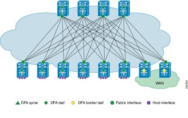
The following figure shows the terms that are used for a Cisco Dynamic Fabric Automation (DFA) deployment. You should understand these terms and definitions before you deploy Cisco DFA.
-
Cisco DFA fabric—A multistage, switching network in which every connected device is reachable through the same number of hops. The Cisco DFA fabric enables the use of a scale-out model for optimized growth.
-
Cisco DFA switch—A leaf, border leaf, or spine device.
-
Leaf—Switches with ports that are connected to ethernet devices, such as servers (host interfaces) and ports (fabric interfaces), that are connected to the Cisco DFA fabric. Leaf switches forward traffic based on the enhanced control plane functionality of Cisco DFA optimized networking, which requires segment ID-based forwarding.
-
Border leaf—Switches that connect external network devices or services, such as firewalls and router ports, to a Cisco DFA fabric. Border leaf switches are similar to leaf switches and can perform segment ID-based forwarding.
-
Spine—Switches through which all leaf and border leaf switches are connected to each other and to which no end nodes are connected. Spine switches forward traffic based on Cisco DFA optimized networking with enhanced or traditional forwarding.
-
Host interface—Leaf to server interfaces that receive traffic for connected VLANs to be extended across the Cisco DFA fabric.
-
Fabric interface—Ports through which Cisco DFA switches are connected to one another.
Cisco Dynamic Fabric Automation Overview
-
Fabric Management—Simplifies workload visibility, optimizes troubleshooting, and automates fabric component configuration.
-
Workload Automation—Integrates with automation and orchestration tools through northbound application programming interfaces (APIs) and also provides control for provisioning fabric components by automatically applying templates that leverage southbound APIs and standard-based protocols. These automation mechanisms are also extensible to network services.
-
Optimized Networking—Uses a simple distributed gateway mechanism to support any subnet, anywhere, concurrently. Existing redundancy models are also used to provide N+ redundancy across the entire fabric.
-
Virtual Fabrics—Extends the boundaries of segmented environments to different routing and switching instances by using logical fabric isolation and segmentation within the fabric. All of these technologies can be combined to support hosting, cloud, and multi-tenancy environments.
-
DCI Automation—Automate the configuration of connecting tenants within the unified fabric to the external world, be it the Internet or other unified fabric networks. These features works in tandem with DCNM (7.1.1 onwards) to enable auto configuration of such requirement.
Note | Global VLAN mutually exclude segment ID, (at least for Layer-2 Traffic). A segment ID is a global identifier, there cannot be two global identifier = VLAN + segment ID, you have to decide one or the other. Global VLANs and segment ID can co-exist in the same fabric, if the outer header is not overlapping. |
- Fabric Management
- Cisco Prime Data Center Network Manager
- Cisco Dynamic Fabric Automation Services Support
- Guidelines and Limitations for Cisco Unified Fabric Automation
Fabric Management
The fabric management network in Cisco Dynamic Fabric Automation represents a dedicated out-of-band network that is responsible for bootstrapping and managing the individual networking devices, such as spines, leafs, and border leaf switches that are controlled by fabric management. The fabric management network is responsible for transporting the protocols that are required for the different fabric management functions. The following table lists the functions and protocols across the fabric management network.
| Function | Protocol |
|---|---|
|
Power On Auto provisioning (POAP) for automatically configuring network devices |
|
|
Fabric discovery |
Simple Network Management Protocol (SNMP) |
|
User-to-machine and machine-to-machine communication |
Extensible Messaging and Presence Protocol (XMPP) |
|
Automated network provisioning |
Lightweight Directory Access Protocol (LDAP) |
|
DCI Automation |
Auto Provisioning of Data Center Interconnect on a border leaf. |
The management network, also known as the management access, is the network administrator-facing interface for accessing fabric management. The management network represents the portion of your network from which you, as the network administrator, can connect to an element manager or a network management station (NMS) and to switches and routers.
The Cisco Prime Data Center Network Manager (DCNM) is a turn-key management system for fabric management, visibility, and an extensible set of functions to more efficiently control the data center fabric. Cisco Prime DCNM uses standards-based control protocol components to provide you with an extensive level of customization and integration with an operations support system (OSS) network.
Cisco Prime Data Center Network Manager
An Open Virtual Appliance (OVA) is a prebuilt software solution that comprises one or more virtual machines (VMs) that are packaged, maintained, updated, and managed as a single unit. The Cisco DCNM OVA includes an application functionality that is necessary for Cisco DFA. Cisco Prime DCNM as an OVA can be deployed on a VMware vSphere infrastructure.
-
Device auto configuration is the process of bringing up the Cisco DFA fabric by applying preset configuration templates to any device that joins the fabric. Auto configuration installs an image or applies the basic configuration.
-
Cable-plan consistency checks the physical connectivity of the fabric against a documented cable-plan for compliance. The lack of compliance prevents specific links from being active and protects the fabric from unwanted errors.
-
Common point of fabric access allows you, as a network administrator, to interact with the fabric as a single entity (system) to simplify queries and to eliminate switch by switch troubleshooting efforts.
-
Automated network provisioning provides a new layer of automation integration in which the data center fabric-switching infrastructure is automatically provisioned for the physical or virtual workload that is being instantiated.
-
Automated profile refresh allows keeping the fabric and the network information in sync in a non-disruptive manner.
-
DCI Automation provides a touchless provisioning of datacenter interconnections for the tenants.
-
Network, virtual fabric, and host visibility is provided by the management GUI and displays a single set of active network elements that belong to an organization in the fabric.
The Cisco DFA DCNM access network is the network administrator facing interface for accessing fabric management and for connecting northbound application program interfaces (APIs) to orchestrators.
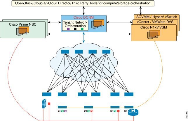
Cisco Dynamic Fabric Automation Services Support
Services such as a firewall, load balancer, and virtual private networks (VPNs) are deployed at the aggregation layer in the traditional data center. In a Cisco DFA deployment, services nodes are deployed at regular leaf switches for both east-west and north-south traffic. Services can be physical or virtual services nodes.
The following figure shows the interaction between the Cisco Prime Network Services Controller (NSC) and the Cisco DFA deployment through Cisco Prime Data Center Network Manager (DCNM).
-
Provides connectivity between Cisco Prime DCNM and the Cisco Prime NSC services orchestrator
-
Automatically populates the Cisco Prime NSC with the organizations, partitions, and networks that are created in Cisco Prime DCNM
-
Populates Cisco Prime DCNM with the services that are stitched through Cisco Prime NSC
-
Allows the use of multiple Cisco Prime NSC instances to match the Cisco Prime DCNM scale
Fabric can be provisioned for services using Cisco UCSD as well without using PNSC for certain scenarios. Containers can be used to orchestrate policies for tenant edge firewall using Physical ASA or ASAv. Containers are integrated with Cisco Prime DCNM to use DFA VLANs to create networks for a firewall’s inside and outside interfaces. VSG service networks can also be orchestrated using UCSD; however, in this scenario, PNSC is required for provisioning the VSG. UCSD deploys all the virtual form factor service nodes (ASAv, VSG) using the port groups with DFA VLANs. These networks are also pushed to Cisco Prime DCNM through the Rest APIs. Note that interaction between PNSC and Cisco Prime DCNM is not needed for this approach; UCSD implements this functionality for services.
In Cisco DFA, configuration profile templates and instantiating the profiles on a leaf switch provide network automation. The templates are extended to support services in Cisco DFA. The profile templates are packaged in Cisco Prime DCNM for the services orchestrator. The table below includes a list of profile templates that are available for Cisco DFA services. It is important that you select the correct profile to orchestrate and automate services in the Cisco DFA fabric.
| Service | Network | Routing | Service Profile |
|---|---|---|---|
|
Edge Firewall |
Host Network |
N/A |
defaultUniversalTfProfile |
|
Edge Firewall |
Static |
serviceNetworkUniversalTfStaticRoutingProfile |
|
|
Dynamic |
serviceNetworkUniversalDynamicRoutingESProfile |
||
|
Tenant External Service Network |
Static |
externalNetworkUniversalTfStaticRoutingESProfile |
|
|
Dynamic |
externalNetworkUniversalDynamicRoutingESProfile |
||
|
Service Node as Router/Default Gateway |
Host Network |
N/A |
defaultNetworkL2Profile |
For NSC Adapter installation information, see the Cisco DCNM 7.1 OVA Installation Guide.
Guidelines and Limitations for Cisco Unified Fabric Automation
-
The fabric management network can support only one Dynamic Host Configuration Protocol (DHCP) server. You can use either the DHCP server in Cisco Prime Data Center Network Manager (DCNM) or another designated DHCP server, but not both.
-
To ensure that Cisco Unified Fabric Automation device auto configuration does not interfere with other DHCP servers on your network, we recommend that you use a dedicated VLAN and subnet for the fabric management network. Cisco Prime DCNM and the Ethernet out-of-band ports of the Cisco Unified Fabric Automation switches (mgmt0) reside in the fabric management network. You have the option to interconnect the fabric management network with your existing out-of-band management network.
-
The management connectivity for Cisco Unified Fabric Automation must come through the Cisco NX-OS device management interface (mgmt0).
-
The management port on any Cisco Unified Fabric Automation switch must be connected to the same management subnet that includes the Cisco Prime DCNM user interface.
-
Every Cisco Unified Fabric Automation switch to be managed by fabric management must be connected to the fabric management network through the Ethernet out-of-band network.
-
A console connection for fabric management is recommended but not required for Cisco Unified Fabric Automation.
-
If Cisco Prime DCNM is your repository server, you must upload the Cisco NX-OS kickstart and system images to Cisco Prime DCNM using the Serial Copy Protocol (SCP) or Secure File Transfer Protocol (SFTP).
Mapping Considerations
In the Cisco UCS Director environment a tenant is represented by a group. A group can have multiple vDCs (Virtual Data Centers). Each vDC is part of one cloud (in VMware terms this is a vCenter). The vDC can have membership to several virtual switches or DVS'. The vSwitches/DVS' can also be part of multiple vDCs. Essentially a vDC is a logical entity associated with a certain set of compute, network, and storage policies. All VMs launched in that particular vDC adhere to those policies.
In the Cisco Unified Fabric Automation environment, there is a three level hierarchy. The hierarchy is composed of organizations (Orgs) which contain one or more partitions (Partitions), which contain one or more networks.
A tenant or group in Cisco UCS Director maps 1:1 with a Cisco Unified Fabric Automation fabric. So in that sense, we have limited a Cisco UCS Director group to be able to create/map to only one Fabric. One or more vDCs are associated with tenants/groups as is the case with Cisco UCS Director today. Multiple partitions can be created under the Fabric from within Cisco UCS Director. There is no binding or direct mapping between a partition and a Cisco UCS Director vDC. However, when a network is created in Cisco UCS Director, a few mandatory inputs are required:
- A Fabric org/tenant/group selection
- A Fabric partition selection
- A Cisco UCS Director vDC selection
- Layer 3 information associated with the network (for example, namely subnet, default gateway, and subnet mask information)
Moreover, a network creation involves the population of the layer 3 information from Cisco UCS Director to the DCNM via appropriate REST APIs as well creation of an appropriate port-group in a vSwitch or set of vSwitches associated with the selected vDC. The information populated in DCNM is employed for auto-provisioning of resources on the Cisco Unified Fabric Automation (physical network infrastructure), while the existing Cisco UCS Director infrastructure is leveraged to allocate appropriate network resources in the virtual infrastructure.
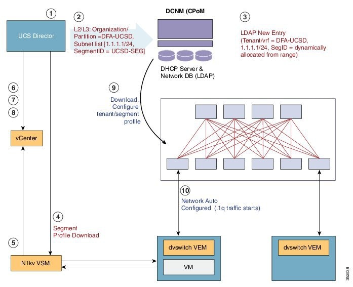
Examining the Orchestration Flow
The orchestration flow essentially involves two processes: creating a Cisco Unified Fabric Automation fabric, Fabric partition, and Fabric network in the first phase and, in the second phase, deploying the VM. The figure and table below describe the entire orchestration flow between Cisco UCS Director and the DCNM.
|
Process Step |
Description |
|---|---|
|
1 |
Create a Cisco Unified Fabric Automation, Fabric partition, or Fabric network. |
|
2 |
Cisco UCS Director sends the new organization/partition/network information to the DCNM. |
|
3 |
The new tenant/vrf entry is added to DCNM. |
|
4 |
A port group is created on the dvSwitch (however, if you are using a Cisco Nexus 1000V switch download the segment profile). |
|
5 |
The port group is made available to the vCenter application. |
|
6 |
Cisco UCS Director initiates the VM creation process on vCenter |
|
7 |
Cisco UCS Director maps the VM nic to the Cisco Cisco Unified Fabric Automation network. |
|
8 |
The VM is powered on. |
|
9 |
The leaf initiates Cisco DFA auto configuration process (based on the VDP or data information). |
|
10 |
The Cisco Cisco Unified Fabric Automation environment is completed (traffic begins to flow if using a dvSwitch). |
 Feedback