- Preface
- New and Changed Information
- Overview of Application Containers
- Implementing Gateway
- Implementing Load Balancing
- Setting Up a Fenced Virtual Container
- Setting Up a Virtual Secure Gateway Application Container
- Setting Up a Fabric Container
- Setting Up a Cisco Application Policy Infrastructure Controller Container
- Managing Application Containers
- Self Service Management Options
Cisco UCS Director Application Container Guide, Release 6.5
Bias-Free Language
The documentation set for this product strives to use bias-free language. For the purposes of this documentation set, bias-free is defined as language that does not imply discrimination based on age, disability, gender, racial identity, ethnic identity, sexual orientation, socioeconomic status, and intersectionality. Exceptions may be present in the documentation due to language that is hardcoded in the user interfaces of the product software, language used based on RFP documentation, or language that is used by a referenced third-party product. Learn more about how Cisco is using Inclusive Language.
- Updated:
- July 10, 2017
Chapter: Setting Up a Cisco Application Policy Infrastructure Controller Container
- Cisco UCS Director and Cisco Application Centric Infrastructure
- Cisco Application Policy Infrastructure Controller
- APIC Application Containers
- ASAv VM Deployment Policy
- APIC Firewall Policy
- APIC Network Policy
- Layer 4 to Layer 7 Service Policy
- Network Device System Parameters Policy
- Application Profiles
- Creating a Virtual Infrastructure Policy
- Creating an Application Container Template
- Creating an APIC Application Container
- Supported Layer 4 to Layer 7 Devices
- Configuring L4-L7 Services
- Deleting L4-L7 Services
- Adding Contracts
- Service Chaining
- Adding VMs to an Existing Container
- Adding Tier/Network
- Adding a Virtual Network Interface Card to a VM
- Deleting a Virtual Network Interface Card
- Adding Bare Metal Servers to an Existing Container
Setting Up a Cisco Application Policy Infrastructure Controller Container
This chapter contains the following sections:
- Cisco UCS Director and Cisco Application Centric Infrastructure
- Cisco Application Policy Infrastructure Controller
- APIC Application Containers
- ASAv VM Deployment Policy
- APIC Firewall Policy
- APIC Network Policy
- Layer 4 to Layer 7 Service Policy
- Network Device System Parameters Policy
- Application Profiles
- Creating a Virtual Infrastructure Policy
- Creating an Application Container Template
- Creating an APIC Application Container
- Supported Layer 4 to Layer 7 Devices
- Configuring L4-L7 Services
- Deleting L4-L7 Services
- Adding Contracts
- Service Chaining
- Adding VMs to an Existing Container
- Adding Tier/Network
- Adding a Virtual Network Interface Card to a VM
- Deleting a Virtual Network Interface Card
- Adding Bare Metal Servers to an Existing Container
Cisco UCS Director and Cisco Application Centric Infrastructure
Cisco UCS Director is a unified infrastructure management solution that provides management from a single interface for compute, network, storage, and virtualization layers. Cisco UCS Director uses a workflow orchestration engine with workflow tasks that support the compute, network, storage, and virtualization layers. Cisco UCS Director supports multitenancy, which enables policy-based and shared use of the infrastructure.
Cisco UCS Director also supports the ability to define contracts between different container tiers, enabling you to apply rules between tiers.
Cisco Application Centric Infrastructure (ACI) allows application requirements to define the network. This architecture simplifies, optimizes, and accelerates the entire application deployment cycle.
The combination of Cisco UCS Director and Cisco ACI enables automatic provisioning and delivery of an application-centric infrastructure.
 Note | To use ACI 1.1(1*), ensure that TLSv1 is enabled in Cisco Application Policy Infrastructure Controller (APIC). In APIC, choose Fabric > Fabric Resources > Pod Polices > Communication > Default and enable TLSv1. |
Cisco Application Policy Infrastructure Controller
The Cisco Application Policy Infrastructure Controller (APIC) is the unified point of automation, management, monitoring, and programmability for the Cisco Application Centric Infrastructure (ACI). The APIC supports the deployment, management, and monitoring of any application anywhere, with a unified operations model for physical and virtual components of the infrastructure. It is the central control engine for the broader cloud network. The APIC programmatically automates network provisioning and control, based on user-defined application requirements and policies. For more information about the APIC, see the Cisco UCS Director APIC Management Guide for this release.
The orchestration feature allows you to automate APIC configuration and management tasks in workflows. A complete list of the APIC orchestration tasks is available in the Workflow Designer, and in the Task Library. For more information about orchestration in Cisco UCS Director, see the Cisco UCS Director Orchestration Guide for this release.
APIC Application Containers
Cisco UCS Director lets you create application containers that support a Cisco Application Policy Infrastructure Controller (APIC). For additional information, see the Cisco UCS Director APIC Management Guide for this release. APIC application containers let you do the following:
-
Establish networks in a VMware environment.
-
Provision multiple VMs from a network.
-
Provide a way to isolate those networks using gateways (for example, ASAv).
-
Allow load balancing the container network using VPX or SDX load balancers.
-
Use a Cisco Application Centric Infrastructure (ACI).
-
Provision a bare metal server and/or VMs.
- APIC Application Container Prerequisites
- APIC Application Container Limitations
- APIC Application Container Creation Process
APIC Application Container Prerequisites
You must perform the following Cisco UCS Director tasks before you can create an APIC application container. For additional information regarding these tasks, refer to the Cisco UCS Director APIC Management Guide for this release.
-
Add and configure an APIC account.
-
Add a resource group.
-
Add a service offering.
-
Add a tenant profile.
-
Add a tag library. See the Cisco UCS Director Administration Guide for this release for information on creating tags.
-
Add a firewall policy (optional).
APIC Application Container Limitations
Cisco UCS Director APIC application containers have the following limitations:
-
Tenant onboarding must be done before container creation and usage.
-
Resource groups must contain the accounts necessary to manage a container's resources. This can be any combination of storage, compute, network, and virtual resources.
-
For application container configuration that requires physical servers, only UCS managed servers are currently supported.
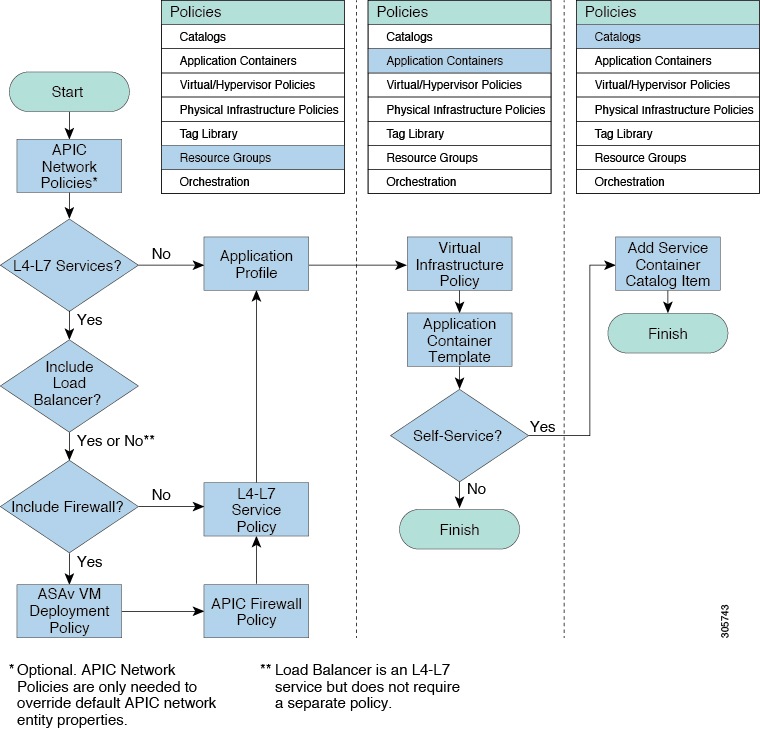
APIC Application Container Creation Process
The figure below illustrates the flow of the APIC Application Container creation process within Cisco UCS Director.
ASAv VM Deployment Policy
The Adaptive Security Virtual Appliance (ASAv) brings full firewall functionality to virtualized environments to secure data center traffic and multi-tenant environments. The ASAv VM deployment policy is used in the Deploy ASAv VM from OVF task.
Adding an ASAv VM Deployment Policy
APIC Firewall Policy
You can optionally create a firewall policy rule that permits network traffic over specific ports between endpoints.
When creating an application profile, you can choose to use a firewall or load balancer for each tier in an application profile. When you create an L4-L7 policy, you can choose a firewall policy from one of the firewall policies that you created in Cisco UCS Director.
The firewall policy is used in the following APIC tasks where you have selected firewall as service:
Adding an APIC Firewall Policy
| Step 1 | Choose . | ||||||||||||||||||||||||||
| Step 2 | On the Resource Groups page, click APIC Firewall Policy. | ||||||||||||||||||||||||||
| Step 3 | Click Add. | ||||||||||||||||||||||||||
| Step 4 | On the Create Firewall Policy screen, complete the following fields:
| ||||||||||||||||||||||||||
| Step 5 | Click Submit. | ||||||||||||||||||||||||||
APIC Network Policy
The APIC network policy is an optional policy used in the network (tier) configuration of the application profile. The APIC network policy overrides the default settings used to provision an APIC application container. You can create a policy to specify tenant or container private networks, create subnetworks, and create end point groups (EPGs).
Adding an APIC Network Policy
| Step 1 | Choose . | ||||||||||||||||||||||||||||||||||||
| Step 2 | On the Resource Groups page, click APIC Network Policy. | ||||||||||||||||||||||||||||||||||||
| Step 3 | Click Add. | ||||||||||||||||||||||||||||||||||||
| Step 4 | On the Create Network Policy screen, complete the following fields:
| ||||||||||||||||||||||||||||||||||||
| Step 5 | Click Submit. | ||||||||||||||||||||||||||||||||||||
Layer 4 to Layer 7 Service Policy
The APIC has an open northbound API that allows you to not only provision services in the fabric, but also to provision Layer 4 to Layer 7 services, such as firewall and load balancer, that attach to the fabric.
Adding a Layer 4 to Layer 7 Service Policy
| Step 1 | Choose . | ||||||||||||||||||||
| Step 2 | On the Resource Groups page, click L4-L7 Service Policy. | ||||||||||||||||||||
| Step 3 | Click Add. | ||||||||||||||||||||
| Step 4 | On the Add L4-L7 Service Policy screen, complete the following fields:
| ||||||||||||||||||||
| Step 5 | Click Submit. | ||||||||||||||||||||
Network Device System Parameters Policy
Network device system parameters policy sets the NTP and SNMP parameters that are needed to be configured on a load balancer (LB) device. The network device system parameters policy is optionally selected during creation of a Layer 4 to Layer 7 service policy to define the NTP and SNMP parameters for configuring a LB device.
While provisioning an APIC container, you have to choose the application profile with the created Layer 4 to Layer 7 service policy so that the corresponding NTP and SNMP parameters are set on device clusters in APIC and configured on the LB device.
Adding a Network Device System Parameters Policy
| Step 1 | Choose . | ||||||||||||||||||||||||||||||||||
| Step 2 | On the Resource Groups page, click Network Device System Parameters Policy. | ||||||||||||||||||||||||||||||||||
| Step 3 | Click Add. | ||||||||||||||||||||||||||||||||||
| Step 4 | On the Create Network Device System Parameters Policy screen, complete the following fields:
| ||||||||||||||||||||||||||||||||||
| Step 5 | Click Submit. | ||||||||||||||||||||||||||||||||||
What to Do Next
You choose the network device policy during creation of a Layer 4 to Layer 7 service policy to define the NTP and SNMP parameters for configuring a LB device.
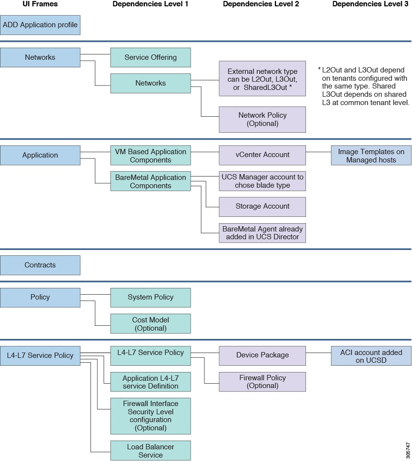
Application Profiles
An application profile is a description of the infrastructure required for the deployment of an application. These infrastructure requirements include bare metal configurations, virtual machines (VMs), L4-L7 policies, and connection policies.
Note | You can perform a container provisioning either in the VMware environment or Hyper-V environment. |
The following image explains the dependencies of the application profile:
- Adding an Application Profile
- Cloning an Application Profile
- Editing an Application Profile
- Deleting an Application Profile
Adding an Application Profile
| Step 1 | Choose . | ||||||||||||||||||||||||
| Step 2 | On the Resource Groups page, click Application Profile. | ||||||||||||||||||||||||
| Step 3 | Click the row with the application profile and choose View from the More Actions drop-down list to view the name, description, and service offering of the application profile, or, choose View Details to see the following:
| ||||||||||||||||||||||||
| Step 4 | Click Add. | ||||||||||||||||||||||||
| Step 5 | On the Profile Specification screen, complete the following fields:
| ||||||||||||||||||||||||
| Step 6 | Click Next. | ||||||||||||||||||||||||
| Step 7 | On the Networks screen, complete the following fields:
| ||||||||||||||||||||||||
| Step 8 | Click Add to configure the tier for application.
On the Add Entry to Networks screen, complete the following fields:
| ||||||||||||||||||||||||
| Step 9 | Click Submit. | ||||||||||||||||||||||||
| Step 10 | Click Next. | ||||||||||||||||||||||||
| Step 11 | On the Application screen, do the following: | ||||||||||||||||||||||||
| Step 12 | On the Application screen, do the following: | ||||||||||||||||||||||||
| Step 13 | Click Next. | ||||||||||||||||||||||||
| Step 14 | On the Contracts screen, define the rule for communication in multi-tier applications.
Contracts are policies that enable inter-End Point Group (inter-EPG) communication. These policies are the rules that specify communication between application tiers. If no contract is attached to the EPG, inter-EPG communication is disabled by default. No contract is required for intra-EPG communication because intra-EPG communication is always allowed. A contract can contain multiple subjects. A subject can be used to realize unidirectional or bidirectional filters. A unidirectional filter is a filter that is used in one direction, either from consumer-to-provider (IN) or from provider-to-consumer (OUT) filter. A bidirectional filter is the same filter that is used in both directions. It is not reflexive. A new contract is created for each source-to-destination network pair. For example, if there are multiple rules defined between Web tier as source and application tier as destination network, a single contract will be created on APIC to hold the contract information between Web tier as source and application tier as destination network. For a contract, a new subject is created if the rule defines unidirectional or bidirectional filter. A subject is reused for multiple rules under same contract depending on whether rule includes unidirectional or bidirectional filter. A new filter is created for a specific rule. A new filter rule is created for every rule defined between networks. | ||||||||||||||||||||||||
| Step 15 | Expand Contracts and click + to add the communication protocol details. | ||||||||||||||||||||||||
| Step 16 | Click Next. | ||||||||||||||||||||||||
| Step 17 | On the Policy screen, do the following: | ||||||||||||||||||||||||
| Step 18 | On the L4-L7 Service Policy screen, check the Configure L4-L7 Service check box to configure the Layer 4 to Layer 7 service in the application profile. If the Configure L4-L7 Service check box is checked, complete the following fields: | ||||||||||||||||||||||||
| Step 19 | Click Submit. |
Cloning an Application Profile
| Step 1 | Choose . | ||||||||||||||||||||||||
| Step 2 | On the Resource Groups page, click Application Profile. | ||||||||||||||||||||||||
| Step 3 | Click the row with the application profile that you want to clone. | ||||||||||||||||||||||||
| Step 4 | From the More Actions drop-down list, choose Clone. | ||||||||||||||||||||||||
| Step 5 | On the Profile Specification screen, complete the following fields:
| ||||||||||||||||||||||||
| Step 6 | Click Next. | ||||||||||||||||||||||||
| Step 7 | On the Networks screen, complete the following fields:
| ||||||||||||||||||||||||
| Step 8 | Click Add to configure the tier for application.
On the Add Entry to Networks screen, complete the following fields:
| ||||||||||||||||||||||||
| Step 9 | Click Next. | ||||||||||||||||||||||||
| Step 10 | On the Application screen, add VM-based application components: | ||||||||||||||||||||||||
| Step 11 | On the Application screen, add bare metal application components: | ||||||||||||||||||||||||
| Step 12 | Click Next. | ||||||||||||||||||||||||
| Step 13 | On the Contracts screen, click + to add the communication protocol details. | ||||||||||||||||||||||||
| Step 14 | Click Next. | ||||||||||||||||||||||||
| Step 15 | On the Policy screen, do the following: | ||||||||||||||||||||||||
| Step 16 | On the L4-L7 Service Policy screen, check the Configure L4-L7 Service check box to configure the Layer 4 to Layer 7 service in the application profile. If the Configure L4-L7 Service check box is checked, complete the following fields: | ||||||||||||||||||||||||
| Step 17 | Click Submit. |
Editing an Application Profile
| Step 1 | Choose . | ||||||||||||||||||||||||
| Step 2 | On the Resource Groups page, click Application Profile. | ||||||||||||||||||||||||
| Step 3 | Click the row with the application profile that you want to edit. | ||||||||||||||||||||||||
| Step 4 | Click Edit. | ||||||||||||||||||||||||
| Step 5 | On the Profile Specification screen, complete the following fields:
| ||||||||||||||||||||||||
| Step 6 | Click Next. | ||||||||||||||||||||||||
| Step 7 | On the Networks screen, complete the following fields:
| ||||||||||||||||||||||||
| Step 8 | Click Add to configure the tier for application.
On the Add Entry to Networks screen, complete the following fields:
| ||||||||||||||||||||||||
| Step 9 | Click Next. | ||||||||||||||||||||||||
| Step 10 | On the Application screen, add VM-based application components: | ||||||||||||||||||||||||
| Step 11 | On the Application screen, add bare metal-based application components: | ||||||||||||||||||||||||
| Step 12 | Click Next. | ||||||||||||||||||||||||
| Step 13 | Click + to add the communication protocol details: | ||||||||||||||||||||||||
| Step 14 | Click Next. | ||||||||||||||||||||||||
| Step 15 | On the Policy screen, do the following: | ||||||||||||||||||||||||
| Step 16 | In the L4-L7 Service Policy screen, edit the Layer 4 to Layer 7 service configuration. | ||||||||||||||||||||||||
| Step 17 | Click Submit. |
Deleting an Application Profile
Note | You cannot delete an application profile that is in use. |
Creating a Virtual Infrastructure Policy
| Step 1 | Choose . | ||||||||||
| Step 2 | On the Application Containers page, click Virtual Infrastructure Policies. | ||||||||||
| Step 3 | Click Add Policy. | ||||||||||
| Step 4 | On the Virtual Infrastructure Policy Specification screen, complete the following fields:
| ||||||||||
| Step 5 | Click Next. | ||||||||||
| Step 6 | On the Virtual Infrastructure Policy - APIC Information screen, complete the following fields.
| ||||||||||
| Step 7 | Click Next. | ||||||||||
| Step 8 | The Virtual Infrastructure Policy - Summary screen displays the current configuration. | ||||||||||
| Step 9 | Click Submit. |
Creating an Application Container Template
Before you can create an APIC application container you must create a template.
Create a virtual infrastructure policy.
| Step 1 | Choose . | ||||||||||
| Step 2 | On the Application Containers page, click Application Container Templates. | ||||||||||
| Step 3 | Click Add Template. | ||||||||||
| Step 4 | On the Add Application Container Template screen, complete the following fields:
| ||||||||||
| Step 5 | Click Next. | ||||||||||
| Step 6 | On the Application Container Template - Select a Virtual infrastructure policy screen, complete the following selections:
| ||||||||||
| Step 7 | Click Next. | ||||||||||
| Step 8 | On the Application Container Template - Options screen, complete the following fields:
| ||||||||||
| Step 9 | Click Next. | ||||||||||
| Step 10 | On the Application Container Template - Setup Workflows screen, select a workflow from the container setup workflow list. | ||||||||||
| Step 11 | Click Next to view the Summary screen. | ||||||||||
| Step 12 | Click
Submit to complete the creation of the application
container template.
|
Creating an APIC Application Container
Once you create an application container template you can use the template administrator to initiate a service request that will create an application container.
Create an application container template.
| Step 1 | Choose . | ||||||||||||||||||||
| Step 2 | On the Application Containers page, click Application Container Templates. | ||||||||||||||||||||
| Step 3 | Choose an APIC template. | ||||||||||||||||||||
| Step 4 | Click Create Container. | ||||||||||||||||||||
| Step 5 | On the Create container from template screen, complete the following fields:
| ||||||||||||||||||||
| Step 6 | Click Submit.
| ||||||||||||||||||||
| Step 7 | Click Application Containers. The new container appears in the Application Containers pane.
|
Supported Layer 4 to Layer 7 Devices
The APIC application container supports the following Layer 4 to Layer 7 devices:
For information about supported firewalls and load balancers, see the Cisco UCS Director Compatibility Matrix.
Configuring L4-L7 Services
APIC application containers support L4-L7 services. This procedure describes how to configure L4-L7 services for an existing container. You can add loadbalancer service using userAPIAddLBService API.
Create an APIC application container.
Note | This section describes how to add an L4-L7 service to an existing application container. You can instead configure L4-L7 services in an APIC application profile, where they will be deployed with every application container using that profile. For more information on configuring L4-L7 services in an application profile, see Layer 4 to Layer 7 Service Policy . |
| Step 1 | Choose . | ||||||||||||||||||||||||||||||||||||||||||||
| Step 2 | On the Application Containers page, click Application Containers. | ||||||||||||||||||||||||||||||||||||||||||||
| Step 3 | Choose an application container in which you want to configure L4-L7 service. | ||||||||||||||||||||||||||||||||||||||||||||
| Step 4 | From the More Actions drop-down list, choose Configure L4-L7 Services. | ||||||||||||||||||||||||||||||||||||||||||||
| Step 5 | On the L4-L7 Configuration screen, complete the following fields:
| ||||||||||||||||||||||||||||||||||||||||||||
| Step 6 | Click Submit. | ||||||||||||||||||||||||||||||||||||||||||||
Adding Firewall Rules
Cisco UCS Director allows an administrator or end user to create an APIC application container with L4-L7 services.
| Step 1 | Choose . | ||||||||||||||||||||||||||
| Step 2 | On the Application Containers page, click Application Containers. | ||||||||||||||||||||||||||
| Step 3 | Double-click an existing application container. | ||||||||||||||||||||||||||
| Step 4 | Choose any L4-L7 service with Firewall service type. The Firewall Rules screen appears. | ||||||||||||||||||||||||||
| Step 5 | Click Add Rule (+) to add a new firewall rule. | ||||||||||||||||||||||||||
| Step 6 | On the Add Firewall Rule screen, complete the following fields:
| ||||||||||||||||||||||||||
| Step 7 | Click Submit. |
To make changes to a firewall rule, choose the firewall rule and click Modify Rule. To remove a firewall rule, choose the firewall rule and click Delete Rule.
Adding Real Servers to Load Balancer Service
Cisco UCS Director allows an administrator or end user to create an APIC application container with L4-L7 services.
| Step 1 | Choose . |
| Step 2 | On the Application Containers page, click Application Containers. |
| Step 3 | Double-click an existing application container. |
| Step 4 | Choose any L4-L7 service with Load Balancer service type. The LB Servers screen appears. |
| Step 5 | Click Add Servers. |
| Step 6 | On the Add Servers screen, expand VMs and check the VM(s) that you want to use. |
| Step 7 | In the Port field, enter the port number. The selected VMs are configured with this port number. |
| Step 8 | Click Submit. |
To remove the load balancer server, click Remove Servers.
Deleting L4-L7 Services
Create and deploy an existing application container with one or more L4-L7 services.
| Step 1 | Choose . |
| Step 2 | On the Application Containers page, click Application Containers. |
| Step 3 | Double-click an application container. |
| Step 4 | Click L4 L7 Services. |
| Step 5 | From the list of L4-L7 services, choose the service that you want to delete. |
| Step 6 | Click Delete. |
| Step 7 | In the confirmation dialog, click Delete. |
Adding Contracts
You can view the contract or security rules created for each application container in Cisco UCS Director. You can add the security rules between the tiers of a same container or different containers within that tenant.
Create an APIC application container.
| Step 1 | Choose . | ||||||||||||||||||||||||||||||||||||
| Step 2 | On the Application Containers page, click Application Containers. | ||||||||||||||||||||||||||||||||||||
| Step 3 | Double-click an existing application container. | ||||||||||||||||||||||||||||||||||||
| Step 4 | Click Contracts. | ||||||||||||||||||||||||||||||||||||
| Step 5 | Click Add Contract (+) to add a new contract. | ||||||||||||||||||||||||||||||||||||
| Step 6 | On the Add Entry to Contracts screen, complete the following fields:
| ||||||||||||||||||||||||||||||||||||
| Step 7 | Click
Submit.
You can
drill down each contract to view the following reports:
| ||||||||||||||||||||||||||||||||||||
Adding Security Rules
You need to drill down each contract to view all the security rules created for each application container in Cisco UCS Director.
Cisco UCS Director allows an administrator and end user to create an APIC application container to add the security rules created for each application container.
| Step 1 | Choose . | ||||||||||||||||||||||||||||
| Step 2 | On the Application Containers page, click Application Containers. | ||||||||||||||||||||||||||||
| Step 3 | Double-click an application container. | ||||||||||||||||||||||||||||
| Step 4 | Click Contracts. | ||||||||||||||||||||||||||||
| Step 5 | Click the row with the contract to which you want to add security rule, and click View Details. | ||||||||||||||||||||||||||||
| Step 6 | Click Security Rules. | ||||||||||||||||||||||||||||
| Step 7 | Click Add to add a security rule. | ||||||||||||||||||||||||||||
| Step 8 | On the Add Contract screen, complete the following fields:
| ||||||||||||||||||||||||||||
| Step 9 | Click Submit. The security rule is created for the application container. | ||||||||||||||||||||||||||||
Deleting Security Rules
Create an APIC application container.
Service Chaining
In an APIC container, you can create both a firewall and a load balancer in series between two networks. This process is called L4-L7 service chaining, or just service chaining, and the resulting firewall - load balancer series is called a service chain.
There are two ways to create a service chain in an APIC container:
-
Create the service chain in an existing container. See Configuring L4-L7 Services.
-
Create both the firewall and the load balancer as part of a container's Application Profile. In this case, both services are provisioned when the container is created. See Adding an Application Profile and Adding a Layer 4 to Layer 7 Service Policy.
Note | A service chain cannot be created in an application container that uses both physical and virtual gateways. |
Adding VMs to an Existing Container
You can add VMs to an existing APIC container in the same way you add VMs to other types of containers. See Adding VMs.
Note | You can add only one network adapter when adding a VM to an existing container using an image. You can use a predefined template with multiple adapters if you created such a template in your application profile. |
Note | You cannot add the VMs to the container through the Add VMs to APIC Container workflow. You can add VMs only by clicking Add VMs or through API. |
Create an APIC application container.
Adding Tier/Network
Create an APIC application container.
| Step 1 | Choose . | ||||||||||||||
| Step 2 | On the Application Containers page, click Application Containers. | ||||||||||||||
| Step 3 | Choose an application container. | ||||||||||||||
| Step 4 | From the More Actions drop-down list, choose Add Tier/Network. | ||||||||||||||
| Step 5 | On the Add Tier/Network screen, complete the following fields:
| ||||||||||||||
| Step 6 | Click Submit. The new tier or network is created. You can select a virtual machine and add vNIC to the container network. |
Adding a Virtual Network Interface Card to a VM
Create and deploy an existing application container with one or more VMs. Before adding the virtual network interface card (vNIC) to the VM, the VM provisioned in the container must run the VMware tools and the ethernet interfaces must be up.
| Step 1 | Choose . | ||||||||||||||
| Step 2 | On the Application Containers page, click Application Containers. | ||||||||||||||
| Step 3 | Double-click an application container. | ||||||||||||||
| Step 4 | Click Virtual Machines. | ||||||||||||||
| Step 5 | Click the row with the VM to which you want to add vNIC. | ||||||||||||||
| Step 6 | From the More Actions drop-down list, choose Add vNICs. | ||||||||||||||
| Step 7 | On the Add vNIC to Container Network screen, complete the following fields:
| ||||||||||||||
| Step 8 | Click Submit. The VM is powered OFF to add vNIC to the container VM. The VM is powered ON once the vNIC is added to the container network. | ||||||||||||||
Deleting a Virtual Network Interface Card
Create and deploy an existing application container with one or more VMs.
| Step 1 | Choose . |
| Step 2 | On the Application Containers page, click Application Containers. |
| Step 3 | Double-click an application container. |
| Step 4 | Click Virtual Machines. |
| Step 5 | Click the row with the VM of the vNIC that you want to delete. |
| Step 6 | Click Delete vNICs. |
| Step 7 | On the Delete VM vNICs screen, choose the vNIC that you want to delete. |
| Step 8 | Click Delete. The VM vNIC is deleted. |
Adding Bare Metal Servers to an Existing Container
Note | Bare metal servers are supported only in APIC containers. |
Before adding bare metal servers to a container, you must add Bare Metal Agent to Cisco UCS Director. See the Cisco UCS Director Bare Metal Agent Installation and Configuration Guide for this release.
| Step 1 | Choose . | ||||||||||||||
| Step 2 | On the Application Containers page, click Application Containers. | ||||||||||||||
| Step 3 | Choose a container to which you want to add BM. | ||||||||||||||
| Step 4 | From the More Actions drop-down list, choose Add BMs. | ||||||||||||||
| Step 5 | On the Add BMs screen, expand Bare Metal Application Components and click Add (+) to add a new BM. | ||||||||||||||
| Step 6 | On the Add Entry screen, complete the following fields:
| ||||||||||||||
| Step 7 | Click Submit. | ||||||||||||||
| Step 8 | To add more BMs, repeat the procedure starting with Step 5. | ||||||||||||||
| Step 9 | When you have defined all the required BMs, click Submit in the Add BMs screen. |
Adding a Disk
Create and deploy an existing application container with one or more bare metal servers.
| Step 1 | Choose . |
| Step 2 | On the Application Containers page, click Application Containers. |
| Step 3 | Double-click an application container. |
| Step 4 | Click Bare Metals. |
| Step 5 | Choose any bare metal server to which the disk is to be added. |
| Step 6 | Click Add Disk. |
| Step 7 | On the Add Disk to BM screen, enter the disk size in GB. |
| Step 8 | Click Submit. |
Deleting a Disk
Create and deploy an existing application container with one or more disks associated with a bare metal server.
| Step 1 | Choose . |
| Step 2 | On the Application Containers page, click Application Containers. |
| Step 3 | Double-click an application container. |
| Step 4 | Click Bare Metals. |
| Step 5 | Choose the bare metal server from which the disk is to be deleted . |
| Step 6 | Click Delete Disk. |
| Step 7 | Choose the BM LUNs identity number that you want to delete from the table. |
| Step 8 | Click Submit. Confirm the deletion in the conformation screen. |
Deleting Bare Metal Servers
Create and deploy an existing application container with one or more bare metal servers.
| Step 1 | Choose . |
| Step 2 | On the Application Containers page, click Application Containers. |
| Step 3 | Double-click an application container. |
| Step 4 | Click Bare Metals. |
| Step 5 | From the list of the bare metal servers, choose the bare metal server that you want to delete. |
| Step 6 | Click Delete BM. The bare metal server and the associated disks are deleted. |
 Feedback