Cohesity Data Cloud on Cisco X-Series Modular Systems
Available Languages
Bias-Free Language
The documentation set for this product strives to use bias-free language. For the purposes of this documentation set, bias-free is defined as language that does not imply discrimination based on age, disability, gender, racial identity, ethnic identity, sexual orientation, socioeconomic status, and intersectionality. Exceptions may be present in the documentation due to language that is hardcoded in the user interfaces of the product software, language used based on RFP documentation, or language that is used by a referenced third-party product. Learn more about how Cisco is using Inclusive Language.
- US/Canada 800-553-2447
- Worldwide Support Phone Numbers
- All Tools
 Feedback
 Feedback
In partnership with:
![]()
![]()
About the Cisco Validated Design Program
The Cisco Validated Design (CVD) program consists of systems and solutions designed, tested, and documented to facilitate faster, more reliable, and more predictable customer deployments. For more information, go to: http://www.cisco.com/go/designzone.
Today’s digitally transformed world is driven by the creativity, speed, and agility of applications and information. As organizations create, use, and manage increasingly higher volumes of data residing everywhere—across hybrid clouds and multiclouds—keeping it safe from ransomware attacks and making it available and productive to the business have become complex and costly. Moreover, today, 46 percent of organizations rely on backup and recovery infrastructure designed in, or before, 2010. Complexities for data management increase because legacy, point solutions no longer work, driving up infrastructure costs and introducing more data silos that expand the attack surface for ransomware. Organizations are grappling with rising security and compliance risks from data residing everywhere and the preparedness to recover rapidly from a data breach.
Cohesity on Cisco UCS X-Series Modular System with Cisco Intersight is a modern, future-ready backup and recovery solution. Moving beyond the limits of traditional platforms, Cisco UCS X-Series Modular Systems provides functionalities of both blade and rack servers by offering compute density, storage capacity, and expandability in a single system, embracing a wide range of workloads in your data center making it a great way to unleash the power of Cohesity DataProtect. Cisco UCS X-Series Modular Systems equipped with all flash storage provides exceptional backup and recovery performance critical during any outages and data-loss incidents such malicious ransomware attacks. This combined with Cohesity DataProtect’s immutable backup snapshots, WORM, data encryption, multi-factor authentication, and granular role-based access controls provides a flexible, hyperscale, software-defined backup and recovery solution that simplifies and modernizes data protection to thwart data loss.
This Cisco Validated Design and Deployment Guide provides prescriptive guidance for the design, setup, configuration, and ongoing use of the Cohesity DataProtect on the Cisco UCS X-Series Modular System. This unique integrated solution provides industry-leading data protection and predictable recovery with modern cloud-managed infrastructure that frees you from yesterday’s constraints by future-proofing your data. Additionally, this solution is delivered as Infrastructure as Code (IaC) to eliminate error-prone manual tasks, allowing quicker and more consistent solution deployments.
For more information on joint Cisco and Cohesity solutions, see https://www.cohesity.com/products/cisco/.
This chapter contains the following:
● Audience
As cyber threats continue to rise, the protection of data sets and workloads is fundamental for any workload, whether it's running on a core data center, edge, or remote site, or in the cloud. However, one of the key challenges for IT and backup administrators is the ability to recover mission-critical applications within the service-level agreements (SLAs), especially during a ransomware attack. Customers are seeking an optimized All Flash data protection solution that not only provides fast recoveries but is also secure, easy to manage and deploy, scalable, efficient, and, most importantly, future ready.
The Cohesity Data Cloud on Cisco UCS X-Series Modular System helps you to overcome these challenges by providing an All Flash data protection solution. This integrated solution comprehensive data security and management capabilities to keep your data safe and your business resilient, and to let you do more with your data, thus reducing your total cost of ownership (TCO). Equally importantly, it delivers incredibly fast performance for comprehensive data management services such as backup and recovery, disaster recovery, file and object services, dev/test, and analytics.
The intended audience for this document includes, but is not limited to, sales engineers, field consultants, professional services, IT managers, IT engineers, partners, and customers who are interested in learning about and deploying an All Flash, secure, and scalable data protection solution for backup and recovery of workloads.
This document describes the design, configuration, deployment steps for the Cohesity Data Cloud Cisco X-Series modular platform managed through Cisco Intersight.
This solution provides a reference architecture and validated deployment procedure for the Cohesity Data Cloud on Cisco UCS X-Series Modular System managed through Cisco Intersight. At a high level, the solution delivers a simple, flexible, and scalable infrastructure approach, enabling fast backup and recoveries of enterprise applications and workloads provisioned either on a converged or hyper-converged platforms. The solution also allows for consistent operations and management across Cisco infrastructure and Cohesity software environment.
The key elements of this solution are as follows:
● Cisco Intersight—is a cloud operations platform that delivers intelligent visualization, optimization, and orchestration for applications and infrastructure across public cloud and on-premises environments. Cisco Intersight provides an essential control point for you to get more value from hybrid IT investments by simplifying operations across on-prem and your public clouds, continuously optimizing their multi cloud environments and accelerating service delivery to address business needs.
● Cisco UCS X-Series Modular System with Cisco Intersight—is a modular system managed from the cloud. It is designed to be shaped to meet the needs of modern applications and improve operational efficiency, agility, and scale through an adaptable, future-ready, modular design. The Cisco UCS X-Series Modular System provides functionalities of both blade and rack servers by offering compute density, storage capacity, and expandability in a single system.
● Cisco UCS X210c M6 Node—is the first computing device to integrate into the Cisco UCS X-Series Modular System. Up to eight compute nodes can reside in the 7-Rack-Unit (7RU) Cisco UCS X9508 Chassis, offering one of the highest densities of compute, I/O, and storage per rack unit in the industry. This solution uses all-NVMe X-Series nodes (X210C) equipped with two third generation (3rd Gen) Intel Xeon Scalable processors and 91.8 TB of all-NVMe storage per node, providing both computing and storage resources with exceptional backup and recovery performance.
● Cohesity Data Cloud—is a unified platform for securing, managing, and extracting value from enterprise data. This software-defined platform spans across core, cloud, and edge, can be managed from a single GUI, and enables independent apps to run in the same environment. It is the only solution built on a hyperconverged, scale-out design that converges backup, files and objects, dev/test, and analytics, and uniquely allows applications to run on the same platform to extract insights from data. Designed with Google-like principles, it delivers true global deduplication and impressive storage efficiency that spans edge to core to the public cloud.
● Cohesity DataProtect—is a high-performance, secure backup and recovery solution. It converges multiple-point products into a single software that can be deployed on-premises or consumed as a service (BaaS). Designed to safeguard your data against sophisticated cyber threats, it offers the most comprehensive policy-based protection for your cloud-native, SaaS, and traditional workloads.
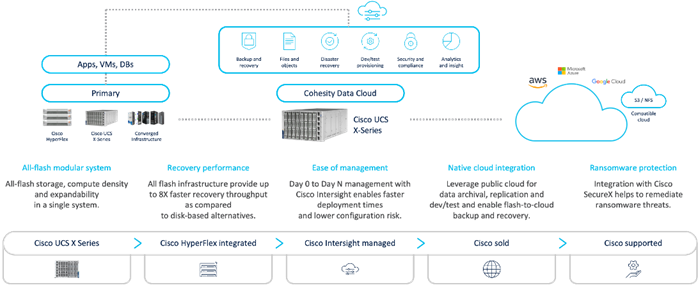
Figure 1 illustrates the key differentiators for the Cohesity Data Cloud on Cisco UCS X-Series Modular System best in class infrastructure, security, and data protection services from Cisco and Cohesity.
This chapter contains the following:
● Cisco Unified Computing System X-Series
● SecureX and Cohesity Data Cloud Integration
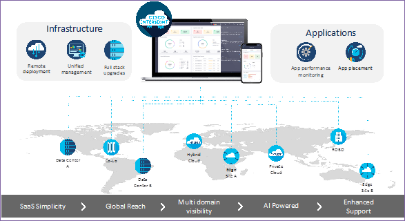
As applications and data become more distributed from core data center and edge locations to public clouds, a centralized management platform is essential. IT agility will be a struggle without a consolidated view of the infrastructure resources and centralized operations. Cisco Intersight provides a cloud-hosted, management and analytics platform for all Cisco HyperFlex, Cisco UCS, and other supported third-party infrastructure deployed across the globe. It provides an efficient way of deploying, managing, and upgrading infrastructure in the data center, ROBO, edge, and co-location environments.
Cisco Intersight provides:
● No Impact Transition: Embedded connector (Cisco HyperFlex, Cisco UCS) will allow you to start enjoying the benefits without a major upgrade.
● SaaS/Subscription Model: SaaS model provides for centralized, cloud-scale management and operations across hundreds of sites around the globe without the administrative overhead of managing the platform.
● Enhanced Support Experience: A hosted platform allows Cisco to address issues platform-wide with the experience extending into TAC supported platforms.
● Unified Management: Single pane of glass, consistent operations model, and experience for managing all systems and solutions.
● Programmability: End to end programmability with native API, SDK’s and popular DevOps toolsets will enable you to deploy and manage the infrastructure quickly and easily.
● Single point of automation: Automation using Ansible, Terraform and other tools can be done through Intersight for all systems it manages.
● Recommendation Engine: Our approach of visibility, insight and action powered by machine intelligence and analytics provide real-time recommendations with agility and scale. Embedded recommendation platform with insights sourced from across Cisco install base and tailored to each customer.
In this solution, Cisco Intersight provides a single global SaaS platform allowing management of either Cisco X-Series or Cisco C-Series Rack servers running the Cohesity Data Cloud deployed across multiple data centers, edge, or remote sites. The life cycle management capabilities that Cisco Intersight offers allows automated Day 0 deployment, continuous monitoring of infrastructure , proactive RMAs, firmware upgrades and easier expansion of Cohesity Clusters.
For more information, go to the Cisco Intersight product page on cisco.com.
Cisco Intersight Virtual Appliance and Private Virtual Appliance
In addition to the SaaS deployment model running on Intersight.com, you can purchase on-premises options separately. The Cisco Intersight virtual appliance and Cisco Intersight private virtual appliance are available for organizations that have additional data locality or security requirements for managing systems. The Cisco Intersight virtual appliance delivers the management features of the Cisco Intersight platform in an easy-to-deploy VMware Open Virtualization Appliance (OVA) or Microsoft Hyper-V Server virtual machine that allows you to control the system details that leave your premises. The Cisco Intersight private virtual appliance is provided in a form factor designed specifically for those who operate in disconnected (air gap) environments. The private virtual appliance requires no connection to public networks or to Cisco network.
Cisco Intersight Assist helps you add endpoint devices to the Cisco Intersight platform. A datacenter could have multiple devices that do not connect directly with the platform. Any device that the Cisco Intersight platform supports but does not connect with directly must have a connection mechanism, and Cisco Intersight Assist provides it. In FlashStack, VMware vCenter and Pure Storage FlashArray connect to the Intersight platform with the help of the Cisco Intersight Assist virtual machine.
Cisco Intersight Assist is available within the Cisco Intersight virtual appliance, which is distributed as a deployable virtual machine contained within an OVA file format. Later sections in this paper have more details about the Cisco Intersight Assist virtual-machine deployment configuration.
The Cisco Intersight platform uses a subscription-based license with multiple tiers. You can purchase a subscription duration of 1, 3, or 5 years and choose the required Cisco UCS server volume tier for the selected subscription duration. Each Cisco endpoint automatically includes a Cisco Intersight Base license at no additional cost when you access the Cisco Intersight portal and claim a device. You can purchase any of the following higher-tier Cisco Intersight licenses using the Cisco ordering tool:
● Cisco Intersight Essentials: Essentials includes all the functions of the Base license plus additional features, including Cisco UCS Central software and Cisco Integrated Management Controller (IMC) supervisor entitlement, policy-based configuration with server profiles, firmware management, and evaluation of compatibility with the Cisco Hardware Compatibility List (HCL).
● Cisco Intersight Advantage: Advantage offers all the features and functions of the Base and Essentials tiers. It also includes storage widgets and cross-domain inventory correlation across compute, storage, and virtual environments (VMware ESXi). OS installation for supported Cisco UCS platforms is also included.
Servers in the Cisco Intersight managed mode require at least the Essentials license. For more information about the features provided in the various licensing tiers, see: https://www.intersight.com/help/saas/getting_started/licensing_requirements
Cisco Unified Computing System X-Series
The Cisco UCS X-Series Modular System is designed to take the current generation of the Cisco UCS platform to the next level with its design that will support future innovations and management in the cloud (Figure 1). Decoupling and moving platform management to the cloud allows the Cisco UCS platform to respond to your feature and scalability requirements much faster and more efficiently. Cisco UCS X-Series state-of-the-art hardware simplifies the datacenter design by providing flexible server options. A single server type that supports a broader range of workloads results in fewer different datacenter products to manage and maintain. The Cisco Intersight cloud management platform manages the Cisco UCS X-Series as well as integrating with third-party devices. These devices include VMware vCenter and Pure Storage to provide visibility, optimization, and orchestration from a single platform, thereby enhancing agility and deployment consistency.
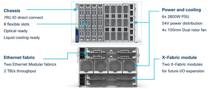
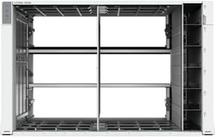
The Cisco UCS X-Series chassis is engineered to be adaptable and flexible. As shown in Figure 3, the only midplane of the UCSX-9508 chassis is just a power-distribution midplane. This innovative design provides fewer obstructions for better airflow. For I/O connectivity, vertically oriented compute nodes intersect with horizontally oriented fabric modules, allowing the chassis to support future fabric innovations. Superior packaging of the Cisco UCSX 9508 chassis enables larger compute nodes, thereby providing more space for actual compute components such as memory, GPU, drives, and accelerators. Improved airflow through the chassis enables support for higher-power components, and more space allows for future thermal solutions (such as liquid cooling) without limitations.
The Cisco UCSX 9508 7-rack-unit (7RU) chassis has 8 flexible slots. These slots can house a combination of compute nodes and a pool of future I/O resources that may include GPU accelerators, disk storage, and nonvolatile memory (NVM). At the top rear of the chassis are two Intelligent Fabric Modules (IFM) that connect the chassis to upstream Cisco UCS 6400 Series Fabric Interconnects. At the bottom rear of the chassis are slots ready to house future X-Fabric modules that can flexibly connect the compute nodes with I/O devices. Six 2800W power supply units (PSUs) provide 54V DC power to the chassis with N, N+1, and N+N redundancy. A higher voltage allows efficient power delivery with less copper and reduced power loss. Efficient, 100-mm, dual counter-rotating fans deliver industry-leading airflow and power efficiency, and optimized thermal algorithms enable different cooling modes to best support your environment.
Cisco UCSX 9108-25G Intelligent Fabric Modules
For the Cisco UCSX 9508 chassis, a pair of Cisco UCS 9108-25G IFMs provide network connectivity. Like the fabric extenders used in the Cisco UCS 5108 Blade Server chassis, these modules carry all network traffic to a pair of Cisco UCS 6400 Series fabric interconnects. IFM also hosts a chassis management controller (CMC). High-speed PCIe-based fabric topology provides extreme flexibility compared to a combination of serial-attached SCSI (SAS), Serial Advanced Technology Attachment (SATA), or Fibre Channel. In contrast to systems with fixed networking components, the design of the Cisco UCSX 9508 enables easy upgrades to new networking technologies as they emerge, making it straightforward to accommodate new network speeds or technologies in the future.
Each IFM supports eight 25-Gb uplink ports for connecting the Cisco UCSX 9508 chassis to the fabric interconnects and thirty-two 25-Gb server ports for the 8 compute nodes. The IFM server ports can provide up to 200 Gbps of unified fabric connectivity per compute node across the two IFMs. The uplink ports connect the chassis to a Cisco UCS fabric interconnect to provide up to 400-Gbps connectivity across the two IFMs. The unified fabric carries management, virtual-machine, and Fibre Channel over Ethernet (FCoE) traffic to the fabric interconnects, where management traffic is routed to the Cisco Intersight cloud operations platform. FCoE traffic is forwarded to the native Fibre Channel interfaces through unified ports on the fabric interconnect (to Cisco MDS switches), and virtual-machine Ethernet traffic is forwarded upstream to the data center network (by Cisco Nexus switches).
![]()
The Cisco UCS X9508 chassis is designed to host up to 8 Cisco UCS X210c M6 servers. Figure 5 shows the hardware details of the Cisco UCS X210c M6 compute node.
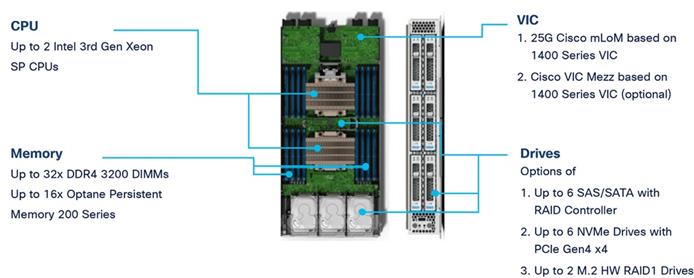
The feature of the Cisco UCS X210c M6 are:
● CPU: The X210c nodes supports, up to two third-generation Intel Xeon scalable processors with up to 40 cores per processor and a 1.5-MB Level 3 cache per core.
● Memory: Supports up to thirty-two 256-GB DDR4-3200 (DIMMs) for a maximum of 8 TB of main memory. You can configure the compute node for up to sixteen 512-GB Intel Optane persistent memory DIMMs for a maximum of 12 TB of memory.
● Disk storage: You can configure up to 6 SAS or SATA drives with an internal (RAID) controller or up to 6 nonvolatile memory express (NVMe) drives. You can add 2 M.2 memory cards to the compute node with RAID 1 mirroring.
● Virtual interface card: You can install up to 2 virtual interface cards, including a Cisco UCS Virtual Interface Card (VIC) modular LOM card (mLOM) 14425, and a mezzanine Cisco VIC 14825 in a compute node.
● Security: The server supports an optional trusted platform module (TPM). Additional security features include a secure a boot field-programmable gate array (FPGA) and ACT2 anti-counterfeit provisions.
Cisco UCS X210c M6 compute nodes support the following two Cisco fourth-generation VIC cards:
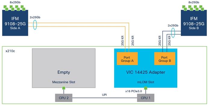
Cisco VIC 14425
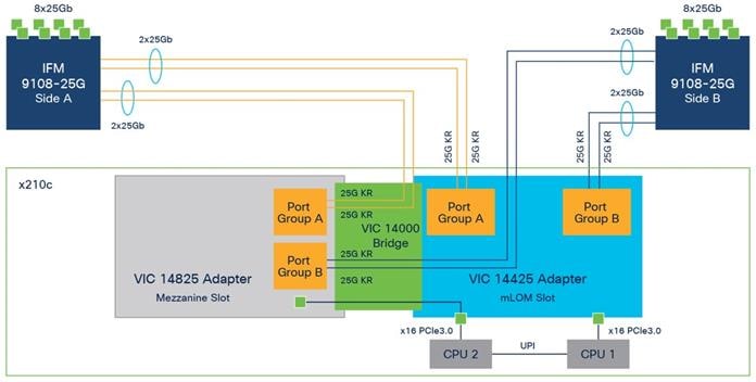
Cisco VIC 14425 fits the mLOM slot in the Cisco X210c compute node and enables up to 50 Gbps of unified fabric connectivity to each of the chassis IFMs for a total of 100 Gbps of connectivity per server (Figure 6). Cisco VIC 14425 connectivity to the IFM and up to the fabric interconnects is delivered through four 25-Gbps connections that are configured automatically as two 50-Gbps port channels. Cisco VIC 14425 supports 256 virtual interfaces (both Fibre Channel and Ethernet) along with the latest networking innovations such as NVMe over Fabric over Remote Direct Memory Access (RDMA), RDMA over Converged Infrastructure (RoCEv2), Virtual Extensible VLAN gateway/Network Virtualization using Generic Routing Encapsulation (VxLAN/NVGRE) offload, and so on.
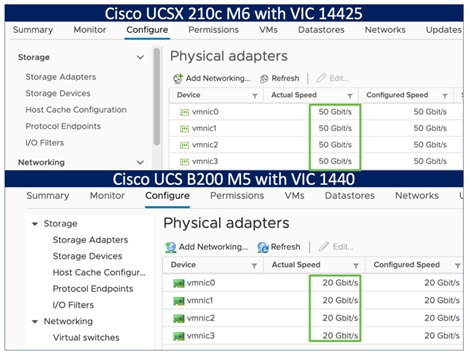
The connections between the fourth-generation Cisco VIC (Cisco UCS VIC 1440) in the Cisco UCS B200 blade servers and the I/O modules in the Cisco UCS VIC 5108 chassis comprise multiple 10-Gbps KR lanes. The same connections between Cisco UCS VIC 14425 and IFM in the Cisco UCS X-Series comprise multiple 25-Gbps KR lanes, resulting in 2.5 times better connectivity in Cisco UCS X210c M6 compute nodes. The following screenshot shows the network interface speed comparison for VMware ESXi installed on the Cisco UCS B200 M5 with a Cisco UCS VIC 1440 and Cisco UCSX 210c M6 with a Cisco UCS VIC 14425.
Cisco UCS VIC 14825
The optional Cisco UCS VIC 14825 fits the mezzanine slot on the server. A bridge card (part number UCSX-V4-BRIDGE) extends the two 50 Gbps of network connections of this VIC up to the mLOM slot and out through the IFM connectors of the mLOM, bringing the total bandwidth to 100 Gbps per fabric for a total bandwidth of 200 Gbps per server (Figure 7).
Cisco UCS 6400 Fabric Interconnects
The Cisco UCS fabric interconnects provide a single point for connectivity and management for the entire Cisco UCS system. Typically deployed as an active-active pair, the fabric interconnects of the system integrate all components into a single, highly available management domain that Cisco UCS Manager or the Cisco Intersight platform manages. Cisco UCS Fabric Interconnects provide a single unified fabric for the system, with low-latency, lossless, cut-through switching that supports LAN, storage-area network (SAN), and management traffic using a single set of cables (Figure 8).
![]()
The Cisco UCS 6454 used in the current design is a 54-port fabric interconnect. This 1RU device includes twenty-eight 10-/25-GE ports, four 1-/10-/25-GE ports, six 40-/100-GE uplink ports, and sixteen unified ports that can support 10-/25-GE or 8-/16-/32-Gbps Fibre Channel, depending on the Small Form-Factor Pluggable (SFP) adapter.
Note: For supporting the Cisco UCS X-Series, you must configure the fabric interconnects in Cisco Intersight managed mode. This option replaces the local management with Cisco Intersight cloud (or appliance)-based management.
SecureX and Cohesity Data Cloud Integration
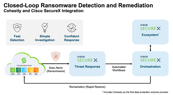
Cohesity with Cisco SecureX is the first-of-its-kind integrated data protection solution with Cisco SecureX. This integration automates the delivery of critical security information to organizations facing ransomware threats, helping to accelerate time to discovery, investigation, and remediation. It leverages the Cohesity Data Cloud’s anomaly detection capability and automates the delivery of alerts into SecureX that indicate data and workloads may have been compromised. Security teams can then leverage Cisco SecureX facilities to expedite investigation within Cisco SecureX, and if needed, initiate a snapshot recovery from within Cisco SecureX for a closed-loop remediation.
Cohesity has built a unique solution based on the same architectural principles employed by cloud hyperscalers managing consumer data but optimized for the enterprise world. The secret to the hyperscalers’ success lies in their architectural approach, which has three major components: a distributed file system—a single platform—to store data across locations, a single logical control plane through which to manage it, and the ability to run and expose services atop this platform to provide new functionality through a collection of applications. The Cohesity Data Cloud platform takes this same three-tier hyperscaler architectural approach and adapts it to the specific needs of enterprise data management.
Helios is the user interface or control plane in which all customers interact with their data and Cohesity products. It provides a single view and global management of all your Cohesity clusters, whether on-premises, cloud, or Virtual Edition, regardless of cluster size. You can quickly connect clusters to Helios and then access them from anywhere using an internet connection and your Cohesity Support Portal credentials.
SpanFS: A Unique File System that Powers the Cohesity Data Cloud Platform
The foundation of the Cohesity Data Cloud Platform is Cohesity SpanFS, a 3rd generation web-scale distributed file system. SpanFS enables the consolidation of all data management services, data, and apps onto a single software-defined platform, eliminating the need for the complex jumble of siloed infrastructure required by the traditional approach.
Predicated on SpanFS, the Data Cloud Platform’s patented design allows all data management infrastructure functions— including backup and recovery, disaster recovery, long-term archival, file services and object storage, test data management, and analytics—to be run and managed in the same software environment at scale, whether in the public cloud, on-premises, or at the edge. Data is shared rather than siloed, stored efficiently rather than wastefully, and visible rather than kept in the dark—simultaneously addressing the problem of mass data fragmentation while allowing both IT and business teams to holistically leverage its value for the first time. In order to meet modern data management requirements, Cohesity SpanFS provides the following as shown in Figure 10.
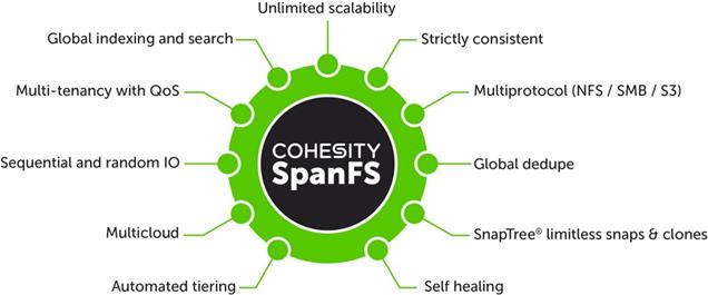
Key SpanFS attributes and implications include the following:
● Unlimited Scalability: Start with as little as three nodes and grow limitlessly on-premises or in the cloud with a pay-as-you-grow model.
● Strictly Consistent: Ensure data resiliency with strict consistency across nodes within a cluster.
● Multi-Protocol: Support traditional NFS and SMB based applications as well as modern S3-based applications. Read and write to the same data volume with simultaneous multiprotocol access.
● Global Dedupe: Significantly reduce data footprint by deduplicating across data sources and workloads with global variable-length deduplication.
● Unlimited Snapshots and Clones: Create and store an unlimited number of snapshots and clones with significant space savings and no performance impact.
● Self-Healing: Auto-balance and auto-distribute workloads across a distributed architecture.
● Automated Tiering: Automatic data tiering across SSD, HDD, and cloud storage for achieving the right balance between cost optimization and performance.
● Multi Cloud: Native integrations with leading public cloud providers for archival, tiering, replication, and protect cloud-native applications.
● Sequential and Random IO: High I/O performance by auto-detecting the IO profile and placing data on the most appropriate media Multitenancy with QoS Native ability to support multiple tenants with QoS support, data isolation, separate encryption keys, and role-based access control.
● Global Indexing and Search: Rapid global search due to indexing of file and object metadata.
Ansible is an open-source tool for Infrastructure as Code (IaC). Ansible is also used for configuration management and application software deployment. Ansible is designed to be agentless, secure, and simple. Ansible available in Red Hat’s Ansible Automation Platform is part of a suite of tools supported by Red Hat. Ansible manages endpoints and infrastructure components in an inventory file, formatted in YAML or INI. The inventory file can be a static file populated by an administrator or dynamically updated. Passwords and other sensitive data can be encrypted using Ansible Vault. Ansible uses playbooks to orchestrate the provisioning. Playbooks are written in human readable YAML format that is easy to understand. Ansible playbooks are executed against a subset of components in the inventory file. From a control machine, Ansible uses SSH or Windows Remote Management to remotely configure and provision target devices in the inventory based on the playbook tasks.
Ansible is used to provision Server Templates for All NVMe X210c nodes installed in Cisco UCS X-Series modular system. The Ansible playbooks detailed in this guide, are specific to the Cohesity Data Cloud configuration for successful deployment on Cisco UCS X-Series X210c nodes.
Architecture and Design Considerations
This chapter contains the following:
● Cisco UCSX 9108-25G IFM Deployment Architecture
● Cisco UCSX 9108-100G IFM Deployment Architecture
● Network Bond Modes with Cohesity and Cisco UCS Fabric Interconnect Managed Systems
Cisco UCSX 9108-25G IFM Deployment Architecture
The Cohesity Data Cloud on Cisco UCS X-Series Modular System requires a minimum four (4) All NVMe X210c nodes. Each Cisco UCS X210c node is equipped with both the compute and All NVMe storage required to operate the Data Cloud and Cohesity storage domains to protect application workloads.
Figure 11 illustrates the deployment architecture overview of Cohesity on Cisco UCS X-Series Modular System, equipped with 4x X210c All NVMe nodes.
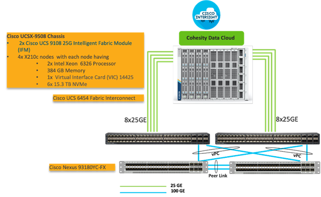
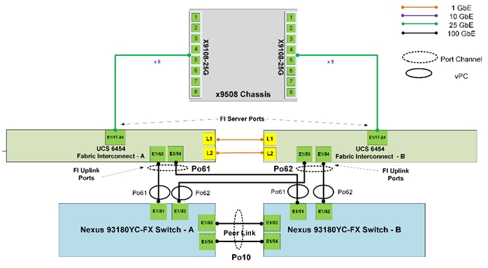
Figure 12 illustrates the cabling diagram for Cohesity on the Cisco UCS X-Series modular System.
The reference hardware configuration includes:
● Two Cisco Nexus 93360YC-FX Switches in Cisco NX-OS mode provide the switching fabric.
● Two Cisco UCS 6454 Fabric Interconnects (FI) provide the chassis connectivity. One 100 Gigabit Ethernet port from each FI, configured as a Port-Channel, is connected to each Cisco Nexus 93360YC-FX.
● One Cisco UCS X9508 Chassis connects to fabric interconnects using Cisco UCSX 9108-25G Intelligent Fabric Modules (IFMs), where eight 25 Gigabit Ethernet ports are used on each IFM to connect to the appropriate FI.
● Cisco UCS X9508 Chassis is equipped with four (4) X210c nodes. Each node is equipped with 2x Intel Xeon Gold 6326 Processor, 384GB and 6x 15.3 TB NVMe providing a raw NVMe storage of ~ 91 TB per node.
● Cisco Intersight as the SaaS management platform for X-Series modular system.
Cisco UCSX 9108-100G IFM Deployment Architecture
The Cisco UCS X-Series Modular System future proofs customer investments by allowing upgrades of network components without the need to upgrade the Cisco UCS X210c certified Cohesity nodes. It allows you to upgrade to new advancements in server and network architecture. In the present architecture, the Cisco UCS X-Series chassis is equipped with 25G IFM modules and fourth generation Cisco UCS Fabric Interconnects. You can easily upgrade to 100G IFM modules and fifth generation Cisco UCS Fabric Interconnects on the same Cisco UCS X- Series 9508 chassis and without any modifications on the existing Cisco UCS X210c Cohesity certified nodes.
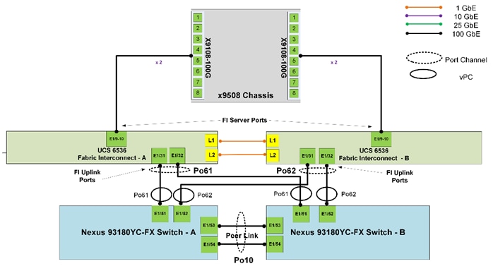
A key benefit of upgrading to the 100G IFM modules are a reduction in cabling and network ports. By leveraging the Cisco UCSX 9108-100G Intelligent Fabric Modules (IFM) and Cisco UCS 6536 Fabric Interconnects, you can reduce your cabling and network ports on the fabric interconnects by 4x. In the existing architecture leveraging Cisco UCSX 9108-25G IFM and eight (8) X210C Cohesity certified nodes, it is recommended to have 8x 25G cables from 25G IFM to FI6454, providing 400G network bandwidth across eight (8) nodes. With the Cisco UCSX 9108-100G IFM and Cisco UCS 6536 Fabric Interconnects, only two (2) 100G cables from each IFM are required and can achieve the same 400G network bandwidth across eight (8) nodes. This reduces the server ports and cables from sixteen (16) to just four (4).
Note: Even though this deployment guide is built with Cisco UCSX 9108-25G IFM and Cisco UCS 6454 Fabric Interconnects, you can leverage the same deployment procedures when installing Cisco UCSX 9108-100G IFM and Cisco UCS 6536 Fabric Interconnects.
Figure 13 illustrates the deployment architecture overview of Cohesity on Cisco UCS X-Series modular system, equipped with 4x X210c All NVMe nodes leveraging Cisco UCSX 9108-100G IFM and Cisco UCS 6536 Fabric Interconnects.
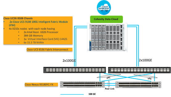
Figure 14 illustrates the cabling diagram for Cohesity on Cisco UCS X-Series modular system with Cisco UCSX 9108-100G IFM and Cisco UCS 6536 Fabric Interconnects.
The reference hardware configuration includes:
● Two Cisco Nexus 93360YC-FX Switches in Cisco NX-OS mode provide the switching fabric.
● Two Cisco UCS 6536 Fabric Interconnects (FI) provide the chassis connectivity. One 100 Gigabit Ethernet port from each FI, configured as a Port-Channel, is connected to each Cisco Nexus 93360YC-FX.
● One Cisco UCS X9508 Chassis connects to fabric interconnects using Cisco UCSX 9108-100G Intelligent Fabric Modules (IFMs), where eight 25 Gigabit Ethernet ports are used on each IFM to connect to the appropriate FI.
● Cisco UCS X9508 Chassis is equipped with four (4) X210c nodes. Each node is equipped with 2x Intel Xeon Gold 6326 Processor, 384GB and 6x 15.3 TB NVMe providing a raw NVMe storage of ~ 91 TB per node.
● Cisco Intersight as the SaaS management platform for the Cisco UCS X-Series modular system.
Network Bond Modes with Cohesity and Cisco UCS Fabric Interconnect Managed Systems
All teaming/bonding methods that are switch independent are supported in the Cisco UCS Fabric Interconnect environment. These bonding modes do not require any special configuration on the switch/UCS side.
The restriction is that any load balancing method used in a switch independent configuration must send traffic for a given source MAC address via a single Cisco UCS Fabric Interconnect other than in a failover event (where the traffic should be sent to the alternate fabric interconnect) and not periodically to redistribute load.
Using other load balancing methods that operate on mechanisms beyond the source MAC address (such as IP address hashing, TCP port hashing, and so on) can cause instability since a MAC address is flapped between UCS Fabric Interconnects. This type of configuration is unsupported.
Switch dependent bonding modes require a port-channel to be configured on the switch side. The fabric interconnect, which is the switch in this case, cannot form a port-channel with the VIC card present in the servers. Furthermore, such bonding modes will also cause MAC flapping on Cisco UCS and upstream switches and is unsupported.
Cisco UCS Servers with Linux Operating System and managed through fabric interconnects, support active-backup (mode 1), balance-tlb (mode 5) and balance-alb (mode 6). The networking mode in the Cohesity operating system (Linux based) deployed on Cisco UCS C-Series or Cisco UCS X-Series managed through a Cisco UCS Fabric Interconnect is validated with bond mode 1 (active-backup). For reference, go to: https://www.cisco.com/c/en/us/support/docs/servers-unified-computing/ucs-b-series-blade-servers/200519-UCS-B-series-Teaming-Bonding-Options-wi.html)
Cisco Intersight uses a subscription-based license with multiple tiers. Each Cisco endpoint (Cisco UCS server, Cisco HyperFlex system, or Cisco UCS Director software) automatically includes a Cisco Intersight Base when you access the Cisco Intersight portal and claim a device.
Cisco Intersight License Tiers
The Cisco Intersight license tiers are:
● Cisco Intersight Essentials—Essentials includes ALL functionality of Base with the additional features including Cisco UCS Central and Cisco IMC Supervisor entitlement, policy-based configuration with Server Profiles, firmware management, and evaluation of compatibility with the Hardware Compatibility List (HCL).
● Cisco Intersight Advantage—Advantage offers all features and functionality of the Base and Essentials tiers.
● Cisco Intersight Premier—In addition to the functionality provided in the Advantage tier, Intersight Premier includes full subscription entitlement for Cisco UCS Director at no additional cost.
More information about Cisco Intersight Licensing and the features supported in each license can be found here: https://intersight.com/help/saas/getting_started/licensing_requirements
In this solution, using Cisco Intersight Advantage License Tier enables the following:
● Configuration of Domain, Chassis Server Profiles for Cohesity on Cisco UCS X-Series modular system.
● Cohesity OS installation for X210c nodes through Cisco Intersight. This requires enabling an NFS/SMB/HTTPS repository which has the certified Cohesity Data Cloud software.
This section details the physical hardware, software revisions, and firmware versions required to install Cohesity Clusters running on Cisco Unified Computing System. A Cohesity on-premises cluster requires a minimum of three physical nodes deployed either on Cisco UCS X-Series or Cisco C-Series Cohesity-certified nodes. To allow minimal resiliency during a single node failure, it is recommended to have a minimum of four Cohesity-certified Cisco UCS nodes.
Table 1 lists the required hardware components and disk options for the Cohesity Data Cloud on Cisco UCS X-Series Modular Systems.
Table 1. Cisco UCS X-Series Modular System for the Cohesity Data Cloud
| Component |
Hardware |
|
| Fabric Interconnects |
Two (2) Cisco UCS 6454 Fabric Interconnects |
|
| Chassis |
Cisco UCS X 9508 Chassis |
|
| Server Node |
4x Cisco UCS X-210C-M6 Server Node for Intel Scalable CPUs |
|
| Processors |
Each server node equipped with two Intel 6326 2.9GHz/185W 16C/24MB |
|
| Memory |
Each server node equipped with 384 GB of total memory using twelve (12) 32GB RDIMM DRx4 3200 (8Gb) |
|
| Disk Controller |
Cisco UCS X10c Compute Pass Through Controller (Front) |
|
| Storage (each server node) |
OS Boot |
2x M.2 (240GB) with M.2 HW RAID Controller |
| NVMe |
6x 15.3 TB NVMe |
|
| Network (Each Server node) |
Cisco UCS VIC 14425 4x25G mLOM for X Compute Node |
|
| IFM |
2 x UCS 9108-25G IFM for 9508 Chassis |
|
Table 2 lists the software components and the versions required for the Cohesity Data Cloud and Cisco UCS X-Series Modular System, as tested, and validated in this document.
| Component |
Version |
| Cohesity Data Cloud |
cohesity-6.6.0d_u6_release-20221204_c03629f0 |
| Cisco Fabric Interconnect 6454 |
4.2 (3d) |
| Intelligent Fabric Management (IFM) UCSX-I-9108-25G |
4.2 (3c) |
| Cisco X210C node |
5.1(0.230054) |
This chapter contains the following:
● Setup Intersight Managed Mode Setup (IMM)
● Setup UCS X9508 Chassis Profile
● Manual Setup Server Template
● Ansible Automation Server Template
● Install Cohesity on Cisco UCS X210c Nodes
● Configure Cohesity Data Cloud
This chapter describes the solution deployment, Cohesity Data Cloud on Cisco UCS X-Series Modular System, with step-by-step procedures for implementing and managing the solution.
Prior to beginning the installation activities, complete the following necessary tasks and gather the required information.
IP addresses for the Cohesity Data Cloud on Cisco UCS X-Series modular system, need to be allocated from the appropriate subnets and VLANs to be used. IP addresses that are used by the system are comprised of the following groups:
● Cisco X-Series Management: These addresses are used and assigned as management IPs for Cisco UCS Fabric interconnects. Two IP addresses are used; one address is assigned to each Cisco UCS Fabric Interconnect, this address should be routable to https://intersight.com or you can have a proxy configuration.
● Cisco UCSX-9108 IFM modules management: Each IFM is managed through an IMC Access policy mapped to IP pools through the chassis profile.
● Cisco UCS X210C node management: Each Cisco UCS X210C is managed through an IMC Access policy mapped to IP pools through the Server Profile. Currently, for Cisco X-Series nodes, only In-Band configuration is supported for IMC Access Policy. One IP is allocated to each of the node configured through In-Band access policy.
● Cohesity Application: These addresses are used by the Linux OS on each Cohesity node, and the Cohesity software. Two IP addresses per node in the Cohesity cluster are required from the same subnet. These addresses can be assigned from the same subnet at the Cisco UCS Management addresses, or they may be separate.
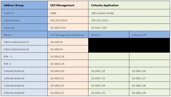
Use the following tables to list the required IP addresses for the installation of a 4-node standard Cohesity cluster and review an example IP configuration.
Note: Table cells shaded in black do not require an IP address.
Table 3. Cohesity Cluster IP Addressing
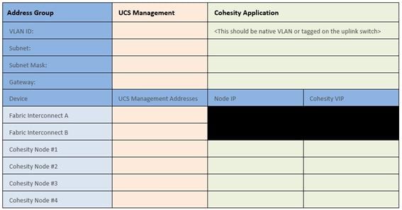
Table 4. Example Cohesity Cluster IP Addressing
DNS servers are required to be configured for querying Fully Qualified Domain Names (FQDN) in the Cohesity application group. DNS records need to be created prior to beginning the installation. At a minimum, it is required to create a single A record for the name of the Cohesity cluster, which answers with each of the virtual IP addresses used by the Cohesity nodes in round-robin fashion. Some DNS servers are not configured by default to return multiple addresses in round-robin fashion in response to a request for a single A record, please ensure your DNS server is properly configured for round-robin before continuing. The configuration can be tested by querying the DNS name of the Cohesity cluster from multiple clients and verifying that all of the different IP addresses are given as answers in turn.
Use the following tables to list the required DNS information for the installation and review an example configuration.
Table 5. DNS Server Information
| Item |
Value |
A Records |
| DNS Server #1 |
|
|
| DNS Server #2 |
|
|
| DNS Domain |
|
|
| UCS Domain Name |
|
|
| Cohesity Cluster Name |
|
|
Table 6. DNS Server Example Information
| Item |
Value |
A Records |
| DNS Server #1 |
10.108.0.6 |
|
| DNS Server #2 |
|
|
| DNS Domain |
|
|
| UCS Domain Name |
AA08-XSeries |
|
Consistent time clock synchronization is required across the components of the Cohesity cluster, provided by reliable NTP servers, accessible for querying in the Cisco UCS Management network group, and the Cohesity Application group.
Use the following tables to list the required NTP information for the installation and review an example configuration.
Table 7. NTP Server Information
| Item |
Value |
| NTP Server #1 |
|
| NTP Server #2 |
|
| Timezone |
|
Table 8. NTP Server Example Information
| Item |
Value |
| NTP Server #1 |
10.108.0.6 |
| NTP Server #2 |
|
| Timezone |
(UTC-8:00) Pacific Time |
Prior to the installation, the required VLAN IDs need to be documented, and created in the upstream network if necessary. Only the VLAN for the Cohesity Application group needs to be trunked to the two Cisco UCS Fabric Interconnects that manage the Cohesity cluster. The VLAN IDs must be supplied during the Cisco UCS configuration steps, and the VLAN names should be customized to make them easily identifiable.
Use the following tables to list the required VLAN information for the installation and review an example configuration.
| Name |
ID |
| <<IN-Band VLAN>> |
|
| <<cohesity_vlan>> |
|
Table 10. VLAN Example Information
| Name |
ID |
| <<IN-Band VLAN>> |
1080 |
| <<cohesity_vlan>> |
1081 |
The Cisco UCS uplink connectivity design needs to be finalized prior to beginning the installation.
Use the following tables to list the required network uplink information for the installation and review an example configuration.
Table 11. Network Uplink Configuration
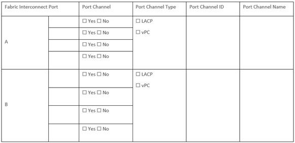
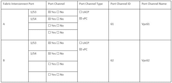
Table 12. Network Uplink Example Configuration
Several usernames and passwords need to be defined or known as part of the Cohesity installation and configuration process.
Use the following tables to list the required username and password information and review an example configuration.
Table 13. Usernames and Passwords
| Account |
Username |
Password |
| Cohesity Administrator |
admin |
<<cohesity_admin_pw>> |
Procedure 1. Create an account on Cisco Intersight
Note: Skip this step if you already have a Cisco Intersight account.
The procedure to create an account in Cisco Intersight is explained below. For more details, go to: https://intersight.com/help/saas/getting_started/create_cisco_intersight_account
Step 1. Visit https://intersight.com/ to create your Intersight account. You must have a valid Cisco ID to create a Cisco Intersight account.
Step 2. Click Create an account.
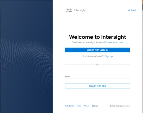
Step 3. Sign-In with your Cisco ID.
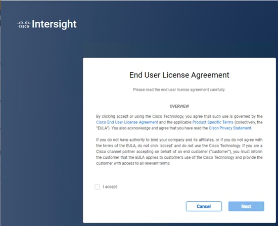
Step 4. Read the End User License Agreement and select I accept and click Next.
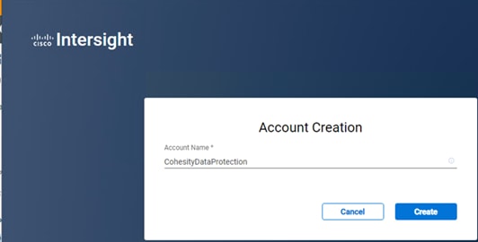
Step 5. Provide a name for the account and click Create.
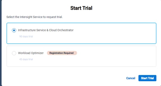
Step 6. Register for Smart Licensing or Start Trial.
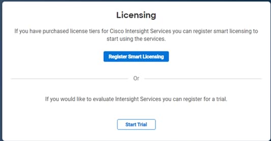
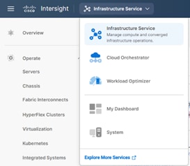
Step 7. Select Infrastructure Service & Cloud Orchestrator and click Start Trial.
Note: Go to: https://intersight.com/help/saas to configure Cisco Intersight Platform.
Setup Intersight Managed Mode Setup (IMM)
Procedure 1. Set up Cisco Intersight Managed Mode on Cisco UCS Fabric Interconnects
The Cisco UCS Fabric Interconnects need to be set up to support Cisco Intersight managed mode. When converting an existing pair of Cisco UCS fabric interconnects from Cisco UCS Manager mode to Intersight Manage Mode (IMM), first erase the configuration and reboot your system.
Note: Converting fabric interconnects to Cisco Intersight Managed Mode is a disruptive process, and configuration information will be lost. You are encouraged to make a backup of their existing configuration. If a software version that supports Intersight Managed Mode (4.1(3) or later) is already installed on Cisco UCS Fabric Interconnects, do not upgrade the software to a recommended recent release using Cisco UCS Manager. The software upgrade will be performed using Cisco Intersight to make sure Cisco UCS X-series firmware is part of the software upgrade.
Step 1. Configure Fabric Interconnect A (FI-A). On the Basic System Configuration Dialog screen, set the management mode to Intersight. All the remaining settings are similar to those for the Cisco UCS Manager Managed Mode (UCSM-Managed).
Cisco UCS Fabric Interconnect A
To configure the Cisco UCS for use in a FlexPod environment in ucsm managed mode, follow these steps:
Connect to the console port on the first Cisco UCS fabric interconnect.
Enter the configuration method. (console/gui) ? console
Enter the management mode. (ucsm/intersight)? intersight
The Fabric interconnect will be configured in the intersight managed mode. Choose (y/n) to proceed: y
Enforce strong password? (y/n) [y]: Enter
Enter the password for "admin": <password>
Confirm the password for "admin": <password>
Enter the switch fabric (A/B) []: A
Enter the system name: <ucs-cluster-name>
Physical Switch Mgmt0 IP address : <ucsa-mgmt-ip>
Physical Switch Mgmt0 IPv4 netmask : <ucs-mgmt-mask>
IPv4 address of the default gateway : <ucs-mgmt-gateway>
DNS IP address : <dns-server-1-ip>
Configure the default domain name? (yes/no) [n]: y
Default domain name : <ad-dns-domain-name>
Following configurations will be applied:
Management Mode=intersight
Switch Fabric=A
System Name=<ucs-cluster-name>
Enforced Strong Password=yes
Physical Switch Mgmt0 IP Address=<ucsa-mgmt-ip>
Physical Switch Mgmt0 IP Netmask=<ucs-mgmt-mask>
Default Gateway=<ucs-mgmt-gateway>
DNS Server=<dns-server-1-ip>
Domain Name=<ad-dns-domain-name>
Apply and save the configuration (select 'no' if you want to re-enter)? (yes/no): yes
Step 2. After applying the settings, make sure you can ping the fabric interconnect management IP address. When Fabric Interconnect A is correctly set up and is available, Fabric Interconnect B will automatically discover Fabric Interconnect A during its setup process as shown in the next step.
Step 3. Configure Fabric Interconnect B (FI-B). For the configuration method, select console. Fabric Interconnect B will detect the presence of Fabric Interconnect A and will prompt you to enter the admin password for Fabric Interconnect A. Provide the management IP address for Fabric Interconnect B and apply the configuration.
Cisco UCS Fabric Interconnect B
Enter the configuration method. (console/gui) ? console
Installer has detected the presence of a peer Fabric interconnect. This Fabric interconnect will be added to the cluster. Continue (y/n) ? y
Enter the admin password of the peer Fabric interconnect: <password>
Connecting to peer Fabric interconnect... done
Retrieving config from peer Fabric interconnect... done
Peer Fabric interconnect Mgmt0 IPv4 Address: <ucsa-mgmt-ip>
Peer Fabric interconnect Mgmt0 IPv4 Netmask: <ucs-mgmt-mask>
Peer FI is IPv4 Cluster enabled. Please Provide Local Fabric Interconnect Mgmt0 IPv4 Address
Physical Switch Mgmt0 IP address : <ucsb-mgmt-ip>
Apply and save the configuration (select 'no' if you want to re-enter)? (yes/no): yes
Procedure 2. Set Up Cisco Intersight Organization
Note: In the present solution, “default” organization is used for all configurations. “Default” organization is automatically created once an Intersight account is created.
An organization is a logical entity which enables multi-tenancy through separation of resources in an account. The organization allows you to use the Resource Groups and enables you to apply the configuration settings on a subset of targets.
In this procedure, a Cisco Intersight organization is created where all Cisco Intersight Managed Mode configurations, including policies, are defined.
Step 1. Log into the Cisco Intersight portal.
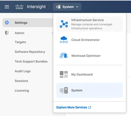
Step 2. Select System. Click Settings (the gear icon).
Step 3. Click Organizations.
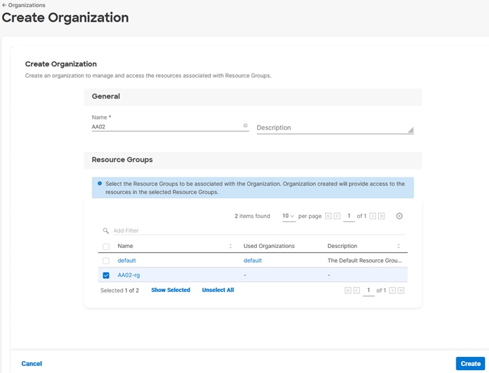
Step 4. Click + Create Organization.
Step 5. Provide a name for the organization (for example, AA02).
Step 6. Select the Resource Group created in the last step (for example, AA02-rg).
Step 7. Click Create.
Procedure 3. Claim Cisco UCS Fabric Interconnects in Cisco Intersight
Note: Make sure the initial configuration for the fabric interconnects has been completed. Log into the Fabric Interconnect A Device Console using a web browser to capture the Cisco Intersight connectivity information.
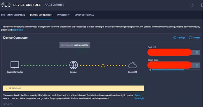
Step 1. Use the management IP address of Fabric Interconnect A to access the device from a web browser and the previously configured admin password to log into the device.
Step 2. Under DEVICE CONNECTOR, the current device status will show “Not claimed.” Note or copy, the Device ID, and Claim Code information for claiming the device in Cisco Intersight.
Step 3. Log into Cisco Intersight.
Step 4. Select System. Click Administration > Targets.
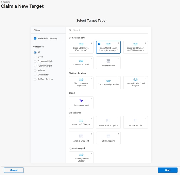
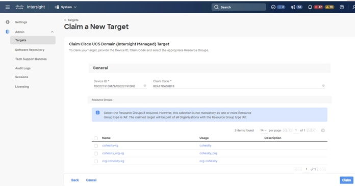
Step 5. Click Claim a New Target.
Step 6. Select Cisco UCS Domain (Intersight Managed) and click Start.
Step 7. Copy and paste the Device ID and Claim from the Cisco UCS FI to Intersight.
Step 8. Select the previously created Resource Group and click Claim.
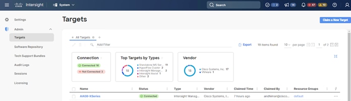
With a successful device claim, Cisco UCS FI should appear as a target in Cisco Intersight:
Step 9. In the Cisco Intersight window, click Settings and select Licensing. If this is a new account, all servers connected to the Cisco UCS domain will appear under the Base license tier. If you have purchased Cisco Intersight licenses and have them in your Cisco Smart Account, click Register and follow the prompts to register this Cisco Intersight account to your Cisco Smart Account. Cisco Intersight also offers a one-time 90-day trial of Advantage licensing for new accounts. Click Start Trial and then Start to begin this evaluation. The remainder of this section will assume Advantage licensing. A minimum of Cisco Intersight Essentials licensing is required to run the Cisco UCS X-Series platform.
Procedure 4. Verify Addition of Cisco UCS Fabric Interconnects to Cisco Intersight
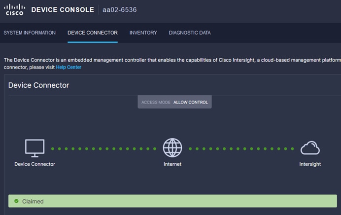
Step 1. Log into the web GUI of the Cisco UCS fabric interconnect and click the browser refresh button.
The fabric interconnect status should now be set to Claimed.
Step 2. Select Infrastructure Service.
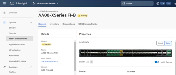
Step 3. Go to the Fabric Interconnects tab and verify the pair of fabric interconnects are visible on the Intersight dashboard.
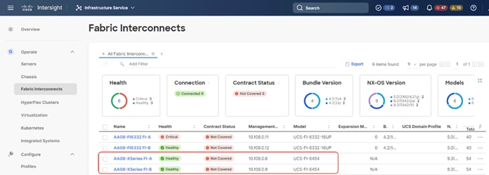
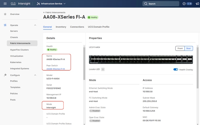
Step 4. You can verify whether a Cisco UCS fabric interconnect is in Cisco UCS Manager Managed Mode or Cisco Intersight managed mode by clicking the fabric interconnect name and looking at the detailed information screen for the fabric interconnect, as shown below:
Procedure 5. Upgrade Fabric Interconnect Firmware using Cisco Intersight
Note: If your Cisco UCS 6454 Fabric Interconnects are not already running firmware release 4.2(2c), upgrade them to 4.2(2c) or to the recommended release.
Note: If Cisco UCS Fabric Interconnects were upgraded to the latest recommended software using Cisco UCS Manager, this upgrade process through Intersight will still work and will copy the Cisco UCS X-Series firmware to the Fabric Interconnects.
Step 1. Log into the Cisco Intersight portal.
Step 2. From the drop-down list, select Infrastructure Service and then select Fabric Interconnects under Operate.
Step 3. Click the ellipses “…”for either of the Fabric Interconnects and select Upgrade Firmware.
Step 4. Click Start.
Step 5. Verify the Fabric Interconnect information and click Next.
Step 6. Select 4.2(3d) release (or the latest release which has the ‘Recommended’ icon) from the list and click Next.
Step 7. Verify the information and click Upgrade to start the upgrade process.
Step 8. Watch the Request panel of the main Intersight screen as the system will ask for user permission before upgrading each FI. Click the Circle with Arrow and follow the prompts on screen to grant permission.
Step 9. Wait for both the FIs to successfully upgrade.
A Cisco UCS domain profile configures a fabric interconnect pair through reusable policies, allows configuration of the ports and port channels, and configures the VLANs and VSANs in the network. It defines the characteristics of and configured ports on fabric interconnects. The domain-related policies can be attached to the profile either at the time of creation or later. One Cisco UCS domain profile can be assigned to one fabric interconnect domain.
Some of the characteristics of the Cisco UCS domain profile in the for Cohesity Helios environment include:
● A single domain profile is created for the pair of Cisco UCS fabric interconnects.
● Unique port policies are defined for the two fabric interconnects.
● The VLAN configuration policy is common to the fabric interconnect pair because both fabric interconnects are configured for the same set of VLANs.
● The Network Time Protocol (NTP), network connectivity, and system Quality-of-Service (QoS) policies are common to the fabric interconnect pair.
Next, you need to create a Cisco UCS domain profile to configure the fabric interconnect ports and discover connected chassis. A domain profile is composed of several policies. Table 14 lists the policies required for the solution described in this document.
Table 14. Policies required for a Cisco UCS Domain Profile
| Policy |
Description |
| VLAN and VSAN Policy |
Network connectivity |
| Port configuration policy for fabric A |
Definition of Server Ports, FC ports and uplink ports channels |
| Port configuration policy for fabric B |
Definition of Server Ports, FC ports and uplink ports channels |
| Network Time Protocol (NTP) policy |
|
| Syslog policy |
|
| System QoS |
|
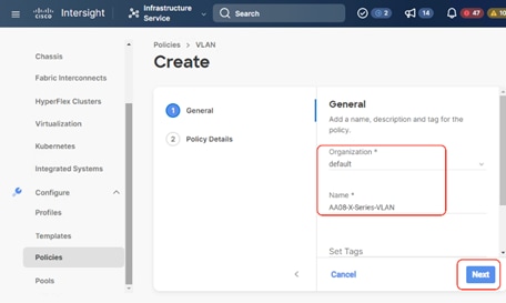
Procedure 1. Create VLAN configuration Policy
Step 1. Select Infrastructure Services.
Step 2. Under Policies, select Create Policy, then select VLAN and click Start.
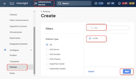
Step 3. Provide a name for the VLAN (for example, AA08-XSeries-VLAN) and click Next.
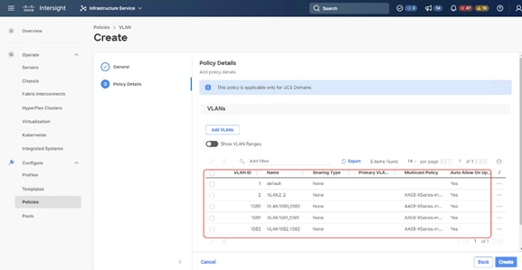
Step 4. Click Add VLANs to add your required VLANs.
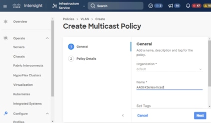
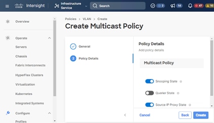
Step 5. Click Multicast Policy to add or create a multicast policy with default settings for your VLAN policy as show below:
Step 6. Add additional VLANs as required in the network setup and click Create.
Note: If you will be using the same VLANs on fabric interconnect A and fabric interconnect B, you can use the same policy for both.
Note: In the event any of the VLANs are marked native on the uplink Cisco Nexus switch, ensure to mark that VLAN native during VLAN Policy creation. This will avoid any syslog errors.
Procedure 2. Create Port Configuration Policy
Note: This policy has to be created for each of the fabric interconnects.
Step 1. Under Policies, for the platform type, select UCS Domain, then select Port and click Start.
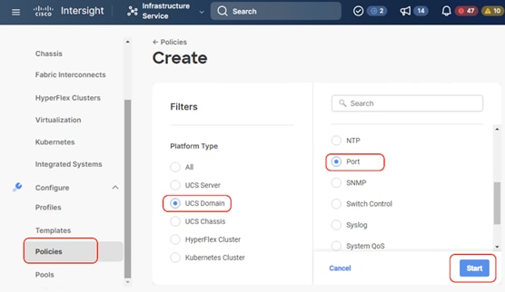
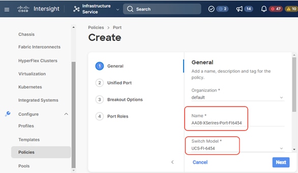
Step 2. Provide a name for the port policy, select the Switch Model (present configuration is deployed with FI 6454) and click Next.
Step 3. Click Next. Define the port roles; server ports for chassis and server connections, Fibre Channel ports for SAN connections, or network uplink ports.
Step 4. If you need Fibre Channel, use the slider to define Fibre Channel ports.
Step 5. Select ports 1 through 16 and click Next, this creates ports 1-16 as type FC with Role as unconfigured. When you need Fibre Channel connectivity, these ports can be configured with FC Uplink/Storage ports.
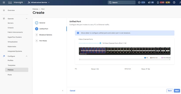
Step 6. Click Next.
Step 7. If required, configure the FC or Ethernet breakout ports, and click Next. In this configuration, no breakout ports were configured. Click Next.
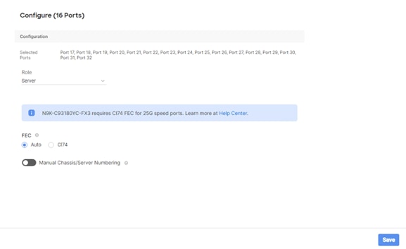
Step 8. To configure server ports, select the ports that have chassis or rack-mounted servers plugged into them and click Configure.
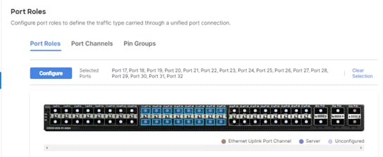
Step 9. From the drop-down list, select Server and click Save.
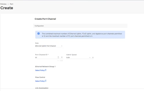
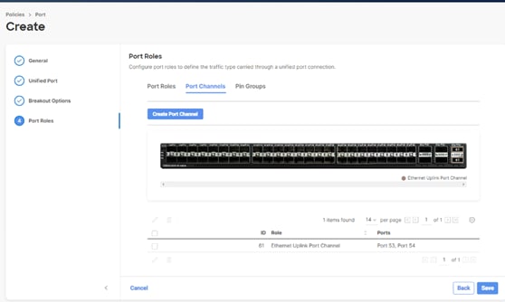
Step 10. Configure the uplink ports as per your deployment configuration. In this setup, port 53/54 are configured as uplink ports. Select the Port Channel tab and configure the port channel as per the network configuration. In this setup, port 53/54 are port channeled and provide uplink connectivity to the Cisco Nexus switch.
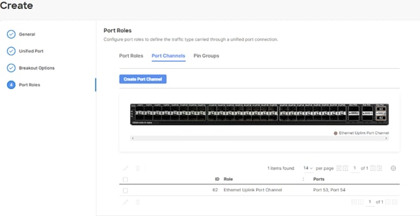
Step 11. Repeat this procedure to create a port policy for Fabric Interconnect B. Configure the port channel ID for Fabric B as per the network configuration. In this setup, the port channel ID 62 is created for Fabric Interconnect B, as shown below:
Procedure 3. Create NTP Policy
Step 1. Under Policies, select Create Policy, then select UCS Domain and then select NTP. Click Start.
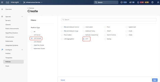
Step 2. Provide a name for the NTP policy.
Step 3. Click Next.
Step 4. Define the name or IP address for the NTP servers. Define the correct time zone.
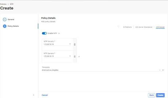
Step 5. Click Create.
Procedure 4. Create syslog Policy
Note: You do not need to enable the syslog server.
Step 1. Under Policies, select Create Policy, then select UCS Domain, and then select syslog. Click Start.
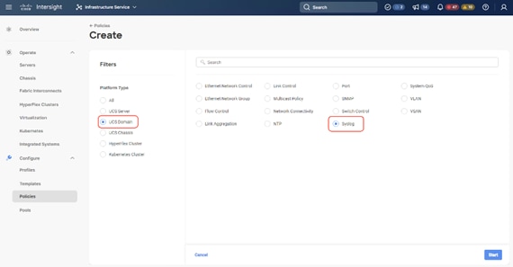
Step 2. Provide a name for the syslog policy.
Step 3. Click Next.
Step 4. Define the syslog severity level that triggers a report.
Step 5. Define the name or IP address for the syslog servers.
Step 6. Click Create.
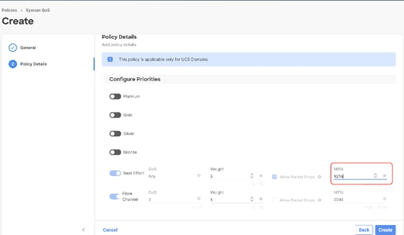
Procedure 5. Create QoS Policy
Note: QoS Policy should be created as per the defined QoS setting on uplink switch. In this Cohesity deployment, no Platinum/Gold/Silver, or Bronze Class of Service (CoS) were defined and thus all the traffic would go through best efforts.
Step 1. Under Policies, select Create Policy, select UCS Domain, then select System QoS. Click Start.
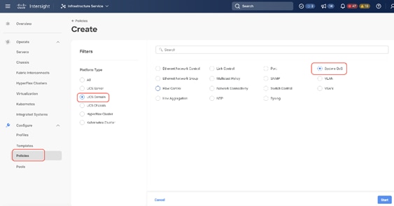
Step 2. Provide a name for the System QoS policy.
Step 3. Click Next.
Step 4. In this Cohesity configuration, no Platinum/Gold/Silver, or Bronze Class of Service (CoS) were defined and thus all the traffic would go through best efforts. Change the MTU of best effort to 9216. Click Create.
Procedure 6. Create Domain Profile
Note: All the Domain Policies created in this procedure will be attached to a Domain Profile. You can clone the Cisco UCS domain profile to install additional Cisco UCS Systems. When cloning the Cisco UCS domain profile, the new Cisco UCS domains use the existing policies for consistent deployment of additional Cisco Systems at scale.
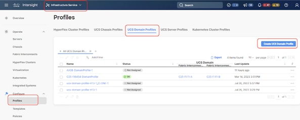
Step 1. Select the Infrastructure Service option and click Profiles.
Step 2. Select UCS Domain Profiles.
Step 3. Click Create UCS Domain Profile.
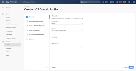
Step 4. Provide a name for the profile (for example, AA08-XSeries-DomainProfile) and click Next.
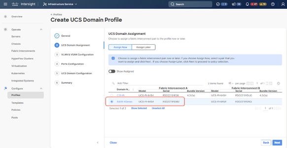
Step 5. Select the fabric interconnect domain pair created when you claimed your Fabric Interconnects.
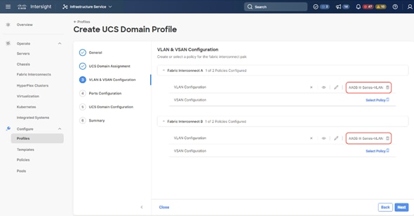
Step 6. Under VLAN & VSAN Configuration, click Select Policy to select the policies created earlier. (Be sure that you select the appropriate policy for each side of the fabric.) In this configuration the VLAN policy is same for both the fabric interconnects.
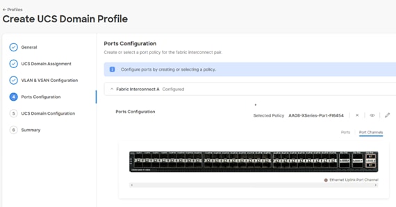
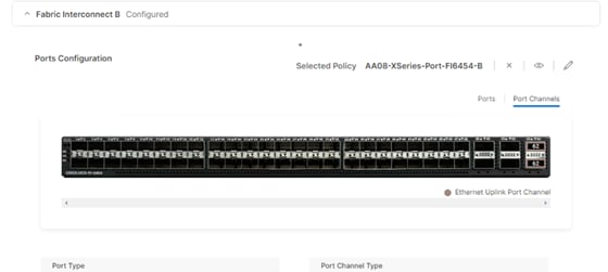
Step 7. Under Ports Configuration, select the port configuration policies created earlier. Each fabric has different port configuration policy. In this setup, only the port channel ID is different across both the Port Configuration Policy.
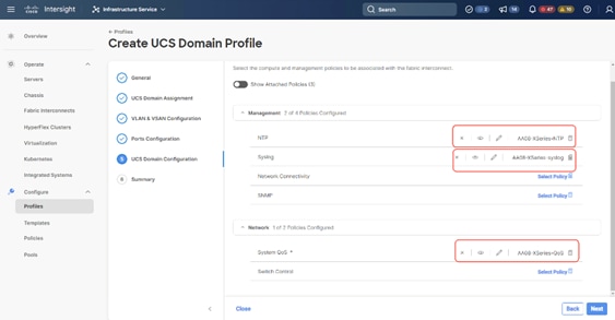
Step 8. Under UCS Domain Configuration, select syslog, System QoS, and the NTP policies you created earlier. Click Next.
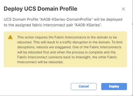
Step 9. Review the Summary and click Deploy. Accept the warning for the Fabric Interconnect reboot and click Deploy.
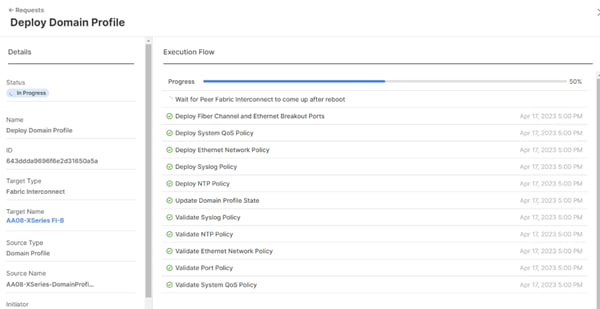
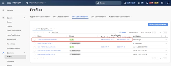
Step 10. Monitor the Domain Profile deployment status and ensure the successful deployment of Domain Profile.
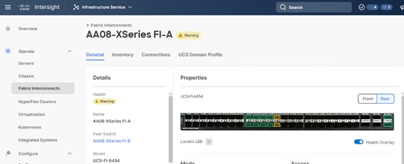
Step 11. Verify the uplink and Server ports are online across both Fabric Interconnects.
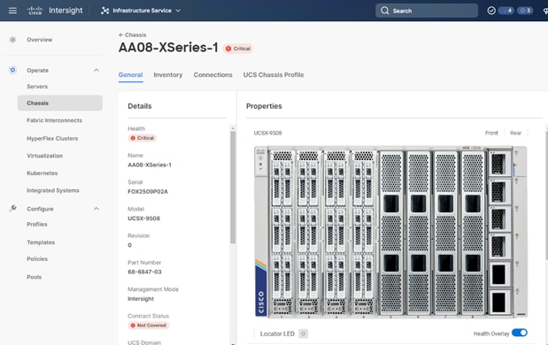
The Cisco UCSX-9508 chassis and Cisco UCS X210c M6 compute nodes are automatically discovered after the successful configuration of the ports using the domain profile. The following screenshots show the front and rear views of the Cisco UCSX-9508 chassis, followed by the Cisco UCS X210c M6 compute nodes:
After the Cisco UCS domain profile has been successfully created and deployed, the policies, including the port policies, are pushed to Cisco UCS fabric interconnects.
Setup UCS X9508 Chassis Profile
A Cisco UCS Chassis profile enables you to create and associate chassis policies to an Intersight Managed Mode (IMM) claimed chassis. When a chassis profile is associated with a chassis, Cisco Intersight automatically configures the chassis to match the configurations specified in the policies of the chassis profile. The chassis-related policies can be attached to the profile either at the time of creation or later.
A chassis profile is composed of several policies. Table 15 lists the policies required for the solution described in this document.
Table 15. Policies required for chassis profile
| Policy |
Description |
| IMC Access Policy for UCS Chassis |
|
| Power Policy |
|
| Thermal Policy |
|
Procedure 1. Create IMC Access Policy for UCS Chassis
Step 1. Select Infrastructure Services.

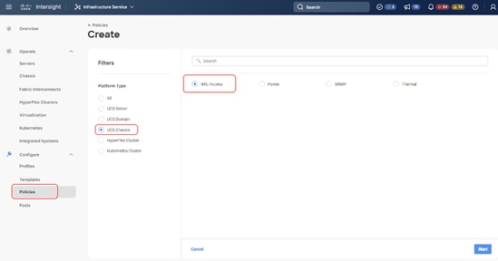
Step 2. Under Policies, select Create Policy. In the platform type select UCS Chassis, then select IMC Access and click Start.
Step 3. Enter a name for Policy (for example, AA08-XSeries-IMC).
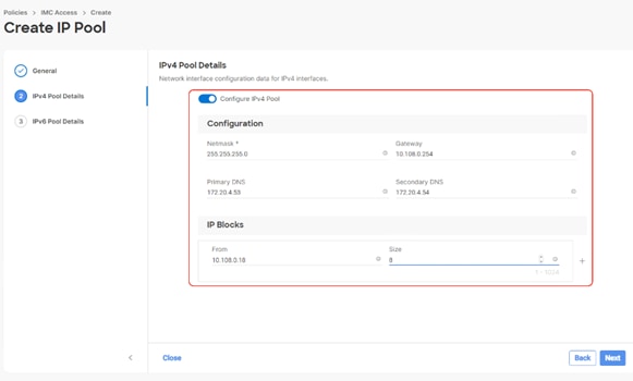
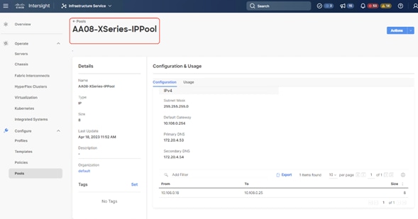
Step 4. Select the UCS Chassis tab, define the IN-Band VLAN ID, select IPv4 configuration, and then select IP Pool. Create an IP Pool and click Create.
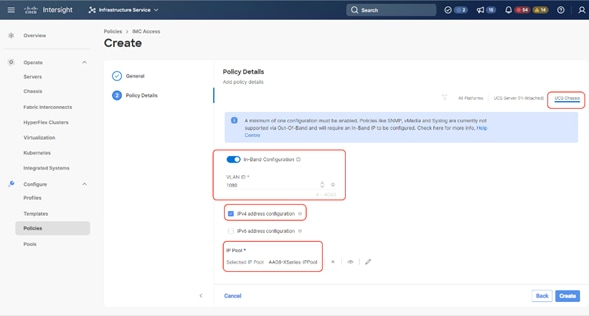
The IP Pool configuration is detailed below:
Procedure 2. Create Power Policy for Chassis
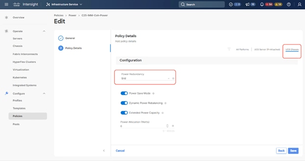
Note: If you have a Cohesity deployment with 8x X210c nodes and a Cisco UCS X-Series chassis equipped with 6x 2800w power supplies, it is recommended to have the Power Redundancy as Grid.
Step 1. Select Infrastructure Services.
Step 2. Under Policies, select Create Policy. In the platform type select UCS Chassis, then select Power and click Start.
Step 3. Name the Power Policy and click Next.
Step 4. Select UCS Chassis. If you have a Cohesity deployment with 8x X210c nodes and a Cisco UCS X-Series chassis equipped with 6x 2800w power supplies, the Power Redundancy as Grid is recommended. Click Create.
Procedure 3. Create Thermal Policy for Chassis
Step 1. Select Infrastructure Services.

Step 2. Under Policies, select Create Policy. In the platform type select UCS Chassis, then select Thermal and click Start.
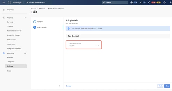
Step 3. Name the Thermal Policy and click Next.
Step 4. Keep the Fan Control as Acoustic, this will allow optimal cooling with balanced performance for Cohesity nodes on X210c. Click Create.
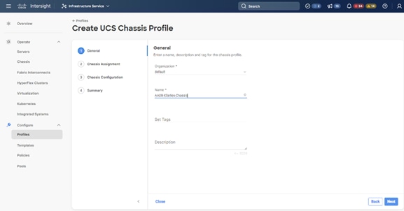
Procedure 4. Create Chassis Profile
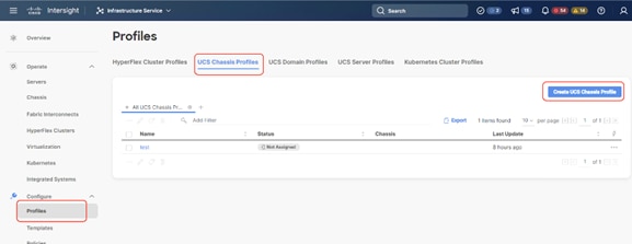
Step 1. Select Infrastructure Service from top left option and click Profiles.
Step 2. Select UCS Chassis Profiles.
Step 3. Click Create UCS Chassis Profile.
Step 4. Enter name for Chassis Profile (for example, AA08-XSeries-Chassis). Click Next.
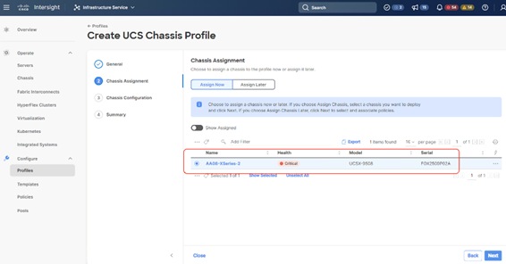
Step 5. Select the Cisco UCS X-Series chassis discovered in the previous procedure. Click Next.
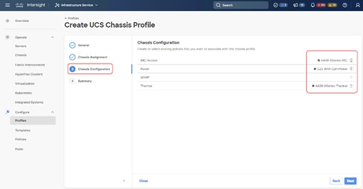
Step 6. Select IMC Access, Power and Thermal polices created in the previous steps. Click Next.
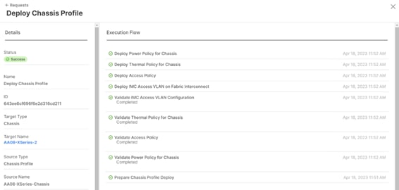
Step 7. Click Deploy to deploy the chassis profile to the chassis discovered. Monitor the chassis profile deployment status and verify its completion.
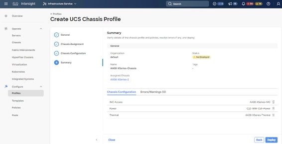
The successful deployment of the Chassis Profile is detailed below:
A server profile template enables resource management by simplifying policy alignment and server configuration. You can create a server profile template by using the server profile template wizard, which groups the server policies into the following categories to provide a quick summary view of the policies that are attached to a profile:
● Pools: KVM Management IP Pool, MAC Pool and UUID Pool
● Compute policies: Basic input/output system (BIOS), boot order, Power, and virtual media policies
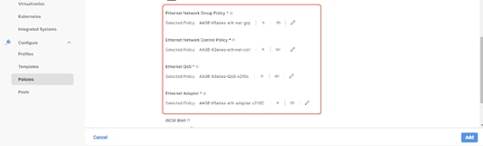
● Network policies: Adapter configuration and LAN policies
◦ The LAN connectivity policy requires you to create an Ethernet network group policy, Ethernet network control policy, Ethernet QoS policy and Ethernet adapter policy
● Storage policies: Not used in Cohesity Deployment
● Management policies: IMC Access Policy for Cisco UCS X210c node, Intelligent Platform Management Interface (IPMI) over LAN; local user; Serial over LAN (SOL); Virtual Media Policy
Procedure 1. Create IP Pool
The IP Pool was previously created during the IMC Access Policy creation for the Cisco UCS X-Series chassis profile as shown below:
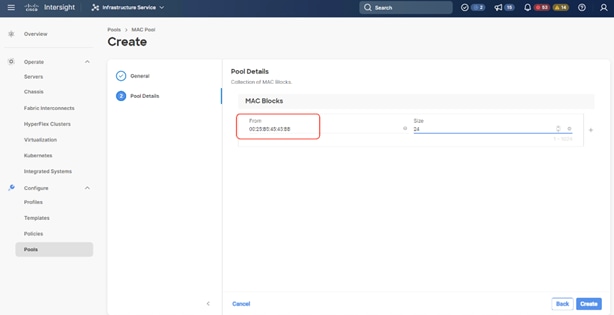
Procedure 2. Create MAC Pool
Note: Best practices mandate that MAC addresses used for Cisco UCS domains use 00:25:B5 as the first three bytes, which is one of the Organizationally Unique Identifiers (OUI) registered to Cisco Systems, Inc. The remaining 3 bytes can be manually set. The fourth byte (for example, 00:25:B5:xx) is often used to identify a specific UCS domain, meanwhile the fifth byte is often set to correlate to the Cisco UCS fabric and the vNIC placement order.
Note: Create two MAC Pools for the vNIC pinned to each of the Fabric Interconnect (A/B). This allows easier debugging during MAC tracing either on Fabric Interconnect or on the uplink Cisco Nexus switch.
Step 1. Click Infrastructure Service, select Pool, and click Create Pool.
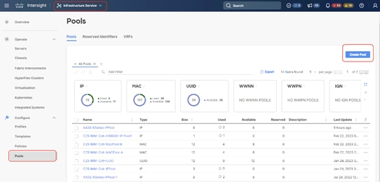
Step 2. Select MAC and click Start.
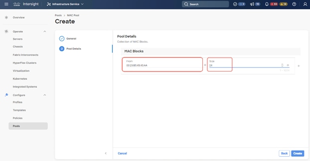
Step 3. Enter a Name for Mac Pool (A) and click Start.
Step 4. Enter the last three octet of MAC address and the size of the Pool and click Create.
Step 5. Repeat this procedure for the MAC Pool for the vNIC pinned to Fabric Interconnect B, shown below:
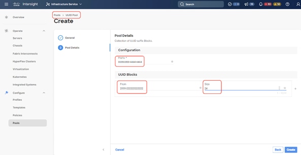
Procedure 3. Create UUID Pool
Step 1. Click Infrastructure Service, select Pool, and click Create Pool.
Step 2. Select UUID and click Start.
Step 3. Enter a Name for UUID Pool and click Next.
Step 4. Enter a UUID Prefix (the UUID prefix must be in hexadecimal format xxxxxxxx-xxxx-xxxx).
Step 5. Enter UUID Suffix (starting UUID suffix of the block must be in hexadecimal format xxxx-xxxxxxxxxxxx).
Step 6. Enter the size of the UUID Pool and click Create. The details are shown below:
Procedure 1. Create BIOS Policy
Table 16 lists the required polices for the BIOS policy.
Table 16. Policies required for domain profile
| Option |
Settings |
| Memory -> Memory Refresh Rate |
1x Refresh |
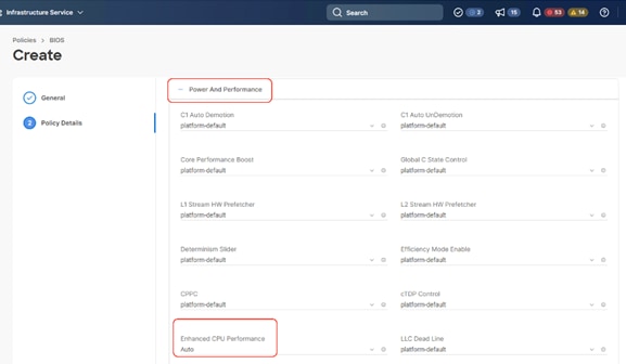
| Power and Performance -> Enhanced CPU Performance |
Auto |
| Processor -> Energy-Performance |
Balanced performance |
| Processor -> CPU Performance |
enterprise |
| Processor -> Processor EPP Enable |
enabled |
| Processor -> EPP Profile |
Balanced performance |
| Processor -> Processor C1E |
disabled |
| Processor -> Processor C6 Report |
enable |
| Processor -> Power Performance Tuning |
os |
| Serial Port -> Serial A Enable |
enabled |
Step 1. Click Infrastructure Service, select Policies, and click Create Policy.
Step 2. Select UCS Server, BIOS and click Start.
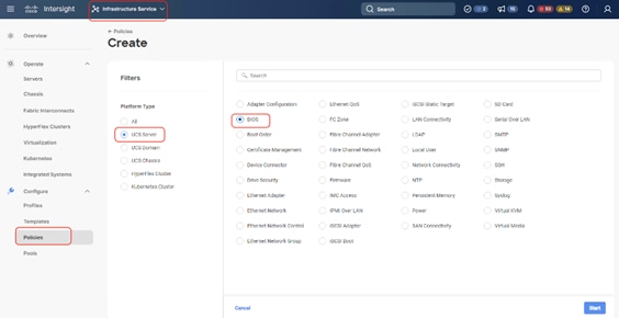
Step 3. Enter a Name for BIOS Policy.
Step 4. Select BIOS Option and change the Memory Refresh Rate to 1X.
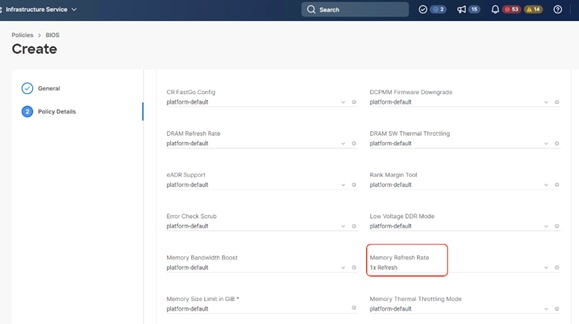
Step 5. Select Power and Performance and change Enhanced CPU Performance to Auto.
Step 6. Select CPU and change the following settings:
● Energy-Performance > Balanced performance
● CPU Performance > enterprise
● Processor EPP Enable > enabled
● EPP Profile > Balanced performance
● Processor C1E > disabled
● Processor C6 Report > enable
● Power Performance Tuning > os
Step 7. Select Serial A Enabled and change to enabled.
Step 8. Click Create.
Procedure 2. Create Boot Order Policy
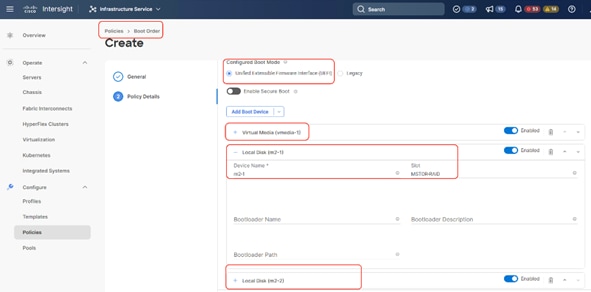
The boot order policy is configured with the Unified Extensible Firmware Interface (UEFI) boot mode, mapping of two M.2 boot drives and the virtual Media (KVM mapper DVD). Cohesity creates a software RAID across 2x M.2 drives provisioned in JBOD mode.
Step 1. Click Infrastructure Service, select Policies, and click Create Policy.
Step 2. Select UCS Server, Boot Order, and click Start.
Step 3. Enter a Name for Boot Order Policy.
Step 4. Under Policy Detail, select UCS Server (FI Attached), and ensure UEFI is checked.
Step 5. Select Add Boot Device and click Local Disk, name the device name as m2-2 and slot as MSTOR-RAID.
Step 6. Select Add Boot Device and click Local Disk, name the device name as m2-1 and slot as MSTOR-RAID.
Step 7. Select Add Boot Device and click vMedia and name the ‘vmedia-1’ device name
Step 8. Ensure vMedia is at the highest boot priority as shown below:
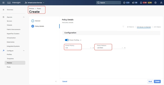
Procedure 3. Create Power Policy
Step 1. Click Infrastructure Service, select Policies, and click Create Policy.
Step 2. Select UCS Server, then select Power and click Start.
Step 3. Name the Power policy, click Next.
Step 4. Select the default power priority, select Power Restore as Last State and click Create. The Power Restore sets the Power Restore State of the Server. In the absence of Cisco Intersight connectivity, the chassis will use this policy to recover the host power after a power loss event.
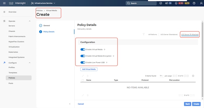
Procedure 4. Create Virtual Media Policy
Step 1. Click Infrastructure Service, select Policies, and click Create Policy.
Step 2. Select UCS Server, then select Virtual Media and click Start.
Step 3. Name the Virtual Media policy and click Next.
Step 4. Select UCS Server (FI Attached), keep the defaults. Click Create.
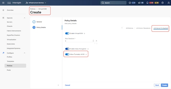
Procedure 5. Create virtual KVM Policy
Step 1. Click Infrastructure Service, select Policies, and click Create Policy.
Step 2. Select UCS Server, then select Virtual KVM and click Start.
Step 3. Name the virtual KVM policy and click Next.
Step 4. Select UCS Server (FI Attached), keep the defaults and enable Allow tunneled KVM. Click Create.
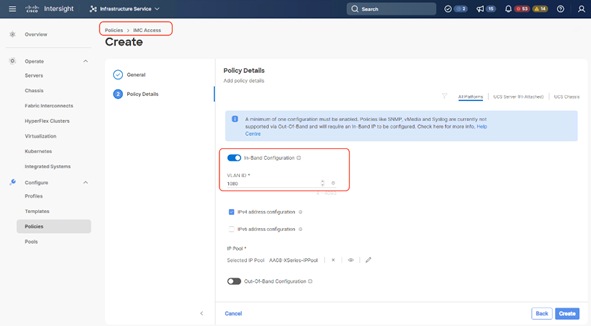
Procedure 6. Create IMC Access Policy for X210C nodes
Currently, the management IP addresses used to access the CIMC on a server can be In-Band addresses, through which traffic traverses the fabric interconnect via the fabric uplink port. For more information, see: https://intersight.com/help/saas/features/servers/configure#server_policies
Note: Currently for Cisco X-Series, IMC access policy can be configured only with In-Band IP addresses.
Note: Ensure no IPMI configuration is defined during the Cohesity Cluster creation. Cohesity software doesn't have dependencies on the IPMI network or user settings. Hardware IPMI events monitoring is through local execution of ipmitool commands.
Note: When the Cohesity cluster is configured, you will see the alert notification “IPMI config is absent.” This is due to the “No IPMI configuration” during the Cohesity cluster creation. Please ignore this alert or contact Cohesity support for more details.
Step 1. Click Infrastructure Service, select Policies, and click Create Policy.
Step 2. Select UCS Server, then select IMC Access and click Start.
Step 3. Name the IMC Access policy, then click Next.
Step 4. Enter the VLAN ID for IN-Band Access, select IP Pool.
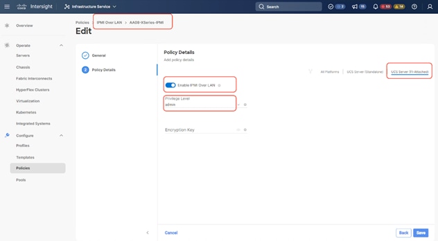
Procedure 7. Create IPMI over LAN Policy
Note: The FI-attached blade servers do not support an encryption key. For the Cisco UCS X-Series deployment, please do not enter an encryption key.
Step 1. Name the IPMI Over LAN policy, then click Next.
Step 2. Select UCS Server (FI-Attached).
Step 3. For the Privilege Level, select admin and do no create an encryption key (FI-attached blade servers do not support an encryption key).
Step 4. Click Save.
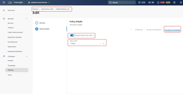
Procedure 8. Create Serial over LAN Policy
Step 1. Click Infrastructure Service, select Policies, and click Create Policy.
Step 2. Select UCS Server, then select Serial Over LAN and click Start.
Step 3. Name the Serial Over LAN policy and click Next.
Step 4. Select UCS Server (FI- Attached) and the select the Baud Rate of 11520. Click Create.
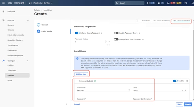
Procedure 9. Create Local User Policy
Step 1. Click Infrastructure Service, select Policies, and click Create Policy.
Step 2. Select UCS Server, then select Local User and click Start.
Step 3. Name the Local User policy and click Next.
Step 4. Add a local user with the name <<kvm-user>> and role as admin and enter a password. This is used to access the server KVM through KVM IP. Click Create.
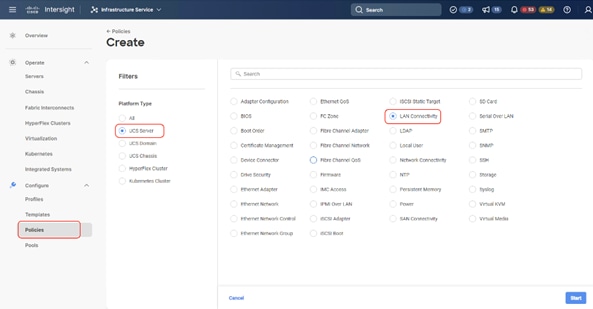
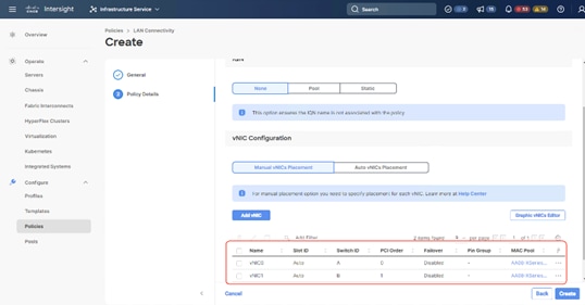
Procedure 10. Create LAN Connectivity Policy
Note: For Cohesity network access, the LAN connectivity policy is used to create two virtual network interfaces (vNICs); vNIC0 and vNIC1. Each vNIC0 and vNIC1 are pinned on Switch ID A and Switch ID B respectively with the same Ethernet network group policy, Ethernet network control policy, Ethernet QoS policy and Ethernet adapter policy. The two vNICs managed by Cohesity for all UCS Managed mode or Intersight Managed mode (connected to Cisco UCS Fabric Interconnect) should be in Active-Backup mode (bond mode 1).
Note: The primary network VLAN for Cohesity should be marked as native or the primary network VLAN should be tagged at the uplink switch.
Note: For UCS Managed or IMM deployments, it is recommended to have only two (2) x vNIC (active-backup) for all Cohesity deployments. To allow multiple network access through VLAN, Cohesity supports configuration of a sub-interface, which allows you to can add multiple VLANs to the vNIC.
Note: This configuration does allow more than two (2) vNICs (required for Layer2 disjoint network); the PCI Order should allow the correct vNIC enumeration by the Operation System.
Step 1. Click Infrastructure Service, select Policies, and click Create Policy.
Step 2. Select UCS Server, then select Lan Connectivity Policy and click Start.
Step 3. Name the LAN Connectivity Policy and select UCS Server (FI Attached).
Step 4. Click Add vNIC.
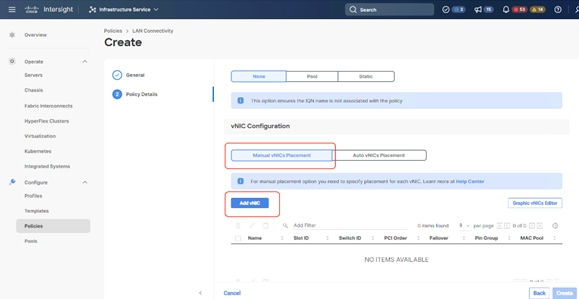
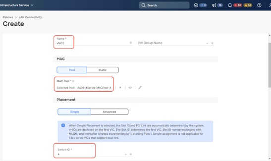
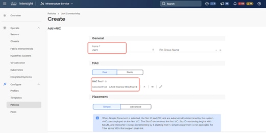
Step 5. Name the vNIC “vNIC0.”
Step 6. For the for vNIC Placement, select Advanced.
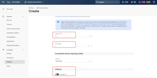
Step 7. Select MAC Pool A previously created, Switch ID A, PCI Order 0.

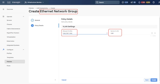
Step 8. Create the Ethernet Network Group Policy; add the allowed VLANs and add the native VLAN. The primary network VLAN for Cohesity should be marked as native or the primary network VLAN should be tagged at the uplink switch.
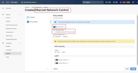
Step 9. Create the Ethernet Network Control policy; name the policy, enable CDP, set MAC Register Mode as All Host VLANs, and keep the other settings as default.
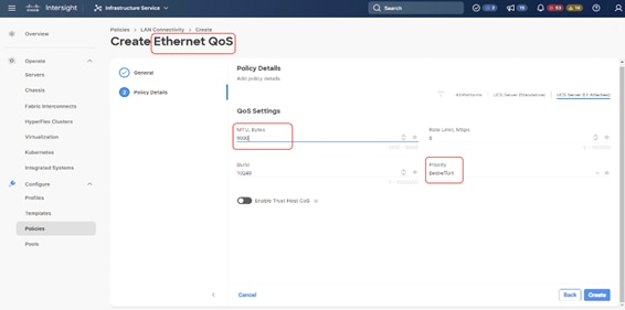
Step 10. Create the Ethernet QoS Policy; edit the MTU to 9000 and keep the Priority as best-effort.
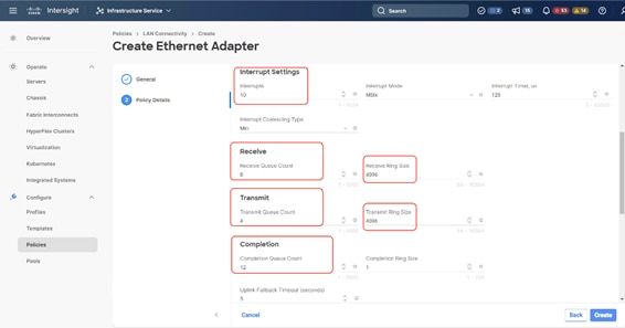
Step 11. Create the Ethernet Adaptor Policy; select UCS Server (FI-Attached), Interrupts=10, Receive Queue Count = 8 Receive Ring Size =4096, Transmit Queue Count = 4, Transmit Ring Size = 4096, Completion Queue = 12, keep the others as default, ensure Receive Side Scaling is enabled.
Step 12. Ensure the four policies are attached and Enable Failover is disabled (default). Click Add.
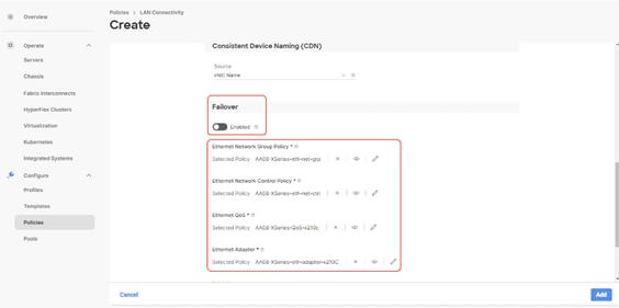
Step 13. Add vNIC as vNIC1. Select the same setting as vNIC0, the only changes shown below.
Step 14. For Switch ID, select B, and the PCI Order should be 1.
Step 15. Optional. The MAC Pool can be selected as the MAC Pool for Fabric B.
Step 16. Select the Ethernet Network Group Policy, Ethernet Network Control Policy, Ethernet QoS, and Ethernet Adapter policy as created for vNIC0 and click Add.
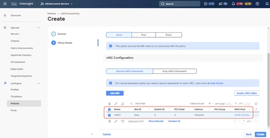
Step 17. Ensure the LAN connectivity Policy is created as shown below with 2x vNIC and click Create.
Procedure 1. Create Server Profile Template
A server profile template enables resource management by simplifying policy alignment and server configuration. All the policies created in previous section would be attached to Server Profile Template. You can derive Server Profiles from templates and attach to X21c nodes deployed for Cohesity. For more information, go to: https://www.intersight.com/help/saas/features/servers/configure#server_profiles
The pools and policies attached to Server Profile Template are listed in Table 17.
Table 17. Policies required for Server profile template
| Pools |
Compute Policies |
Network Policies |
Management Policies |
| KVM Management IP Pool |
BIOS Policy |
LAN Connectivity Policy |
IMC Access Policy |
| MAC Pool for Fabric A/B |
Boot Order Policy |
Ethernet Network Group Policy |
IPMI Over LAN Policy |
| UUID Pool |
Power Policy |
Ethernet Network Control Policy |
Local User Policy |
|
|
Virtual Media |
Ethernet QoS Policy |
Serial Over LAN Policy |
|
|
|
Ethernet Adapter Policy |
Virtual KVM Policy |
Step 1. Click Infrastructure Service, select Templates, and click Create UCS Server Profile Template.
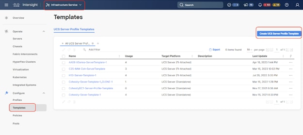
Step 2. Name the Server Profile Template, select UCS Sever (FI-Attached) and click Next.
Step 3. Select UUID Pool and all Compute Policies created in the previous section. Click Next.
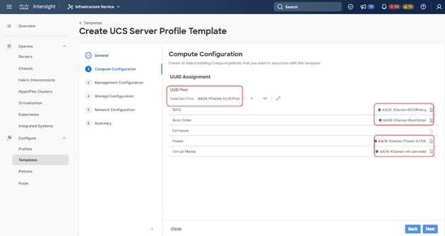
Step 4. Select all Management Configuration Policies and attach to the Server Profile Template.
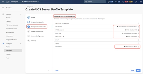
Step 5. Skip Storage Polices and click Next.
Step 6. Under Network Configuration, select the LAN connectivity Policy created in the previous section and click Next.
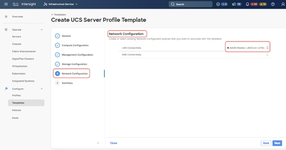
Step 7. Verify the summary and click Close. This completes the creation of Server Profiles. The details of the policies attached to the Server Profile Template are detailed below.
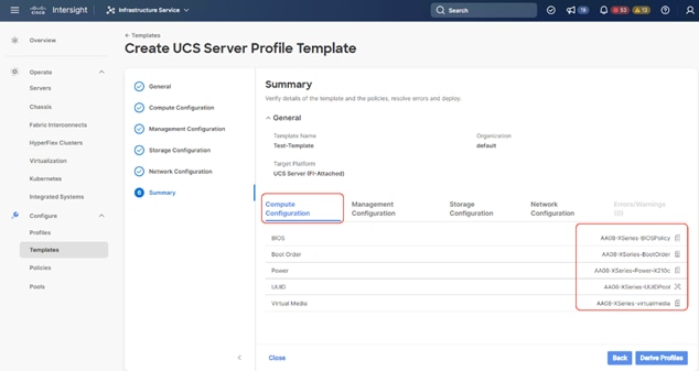
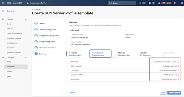
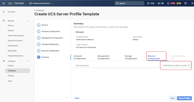
Ansible Automation Server Template
This section describes the automated creation of the Server Profile Template validated for Cisco UCS X210c nodes certified for the Cohesity Data Cloud. The deployment is automated using Red Hat Ansible playbooks available in the Cisco UCS Solutions GitHub repository. The automation will focus on the Day0 installation of Cisco UCS Server Profile Templates.
Note: Make sure the Domain Profile and Chassis Profile are already created and deployed.
The ansible automation creates a Server Profile Template attached to the Server Pools and Policies. These Server Pools and Policies will be created as part of automation. For more information, go to: https://developer.cisco.com/codeexchange/github/repo/ucs-compute-solutions/intersight_cohesity_xseries_ansible/
● Pools: KVM Management IP Pool, MAC Pool and UUID Pool
● Compute policies: Basic input/output system (BIOS), boot order, Power, and virtual media policies
● Network policies: Adapter configuration and LAN policies
The LAN connectivity policy requires you to create an Ethernet network group policy, Ethernet network control policy, Ethernet QoS policy and Ethernet adapter policy
● Management policies: IMC Access Policy, Intelligent Platform Management Interface (IPMI) over LAN; local user; Serial over LAN (SOL); Virtual Media Policy
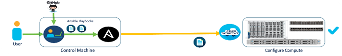
Table 18 lists the configuration parameters.
Table 18. Configuration Parameters
| Variable |
Variable Name |
Value |
Additional Info |
| Git Hub Repo |
- |
https://github.com/ucs-compute-solutions/intersight_cohesity_xseries_ansible |
|
| Variable need to be changed and require input |
|
Variable that requires customer inputs are part of group_vars/ |
|
| Variable that does not typically require customer input (for example, descriptions and so on) |
|
role_name/defauls/main.yml |
|
Prerequisites for the Ansible Playbook
Procedure 1. Prerequisite – Setup an Ansible Control Node running MacOS
Note: The Ansible workstation is running MacOS in this setup.
To install on other operating systems, see: https://docs.ansible.com/ansible/latest/installation_guide/installation_distros.html
For additional information, see the Ansible Installation Guide: https://docs.ansible.com/ansible/latest/installation_guide/intro_installation.html#
Step 1. Ansible control node requires Python 3.8 or higher. Verify if it is already installed.
$ python3 -V
![]()
If Python is not installed or needs to be upgrade, use the commands below to install it.
$ brew install python3
-OR-
$ brew upgrade python3
Step 2. Verify that you have the Python package manager (pip). The python installation should automatically install pip.
$ python3 -m pip -V
![]()
Step 3. If pip is not installed or needs to be upgraded, run the following commands.
$ curl https://bootstrap.pypa.io/get-pip.py -o get-pip.py
$ python3 get-pip.py
-OR-
$ pip3 install --upgrade pip
Step 4. (Optional) Create Virtual Environment (venv) using Python and activate it for use.
$ python3 -m venv <venv_name>
$ python3 -m venv venv1
$ source ./venv1/bin/activate
To deactivate: deactivate
Create aliases (example): alias switchto_venv=‘source ./venv1/bin/activate’
Step 5. Install Ansible on workstation in virtual environment (optional); other useful commands are provided.
(venv1)$ pip install ansible # not necessary to specify python version in venv
(venv1)$ which ansible
(venv1)$ ansible –-version
(venv1)$ ansible –h
(venv1)$ pip install –-upgrade ansible
Step 6. Verify the path and version of python is what you want Ansible to use:
(venv1)$ ansible –-version
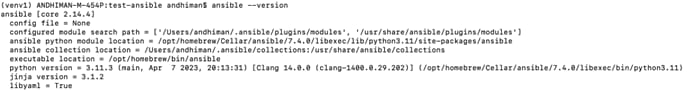
Step 7. Install GIT. It might already be installed on MacOS through other tools. Otherwise install git as follows:
(venv1) $ brew install git # not necessary to execute this in venv
Step 8. Grep for intersight ansible collection:
(venv1) ANDHIMAN-M-454P:intersight_cohesity_xseries_ansible andhiman$ ansible-galaxy collection list | grep intersight
cisco.intersight 1.0.24
Step 9. Upgrade or install the latest cisco.intersight ansible collection:
(venv1) ANDHIMAN-M-454P:intersight_cohesity_xseries_ansible andhiman$ ansible-galaxy collection install cisco.intersight
Starting galaxy collection install process
Process install dependency map
Starting collection install process
Downloading https://galaxy.ansible.com/download/cisco-intersight-1.0.27.tar.gz to /Users/andhiman/.ansible/tmp/ansible-local-62549d2f09vz2/tmpru15728y/cisco-intersight-1.0.27-r1ubuagf
Installing 'cisco.intersight:1.0.27' to '/Users/andhiman/.ansible/collections/ansible_collections/cisco/intersight'
cisco.intersight:1.0.27 was installed successfully
(venv1) ANDHIMAN-M-454P:intersight_cohesity_xseries_ansible andhiman
Setup and Configure Ansible Playbook
Procedure 1. Git Hub repository for Cisco UCS Server Templates
To access the Ansible playbooks in the GitHub repository (repo), clone the Git Hub repo as outlined below. The cloning will create a completely new copy of the repo in the location specified on the Ansible workstation. The repo is located here: https://github.com/ucs-compute-solutions/intersight_cohesity_xseries_ansible directory.
Step 1. From the Ansible workstation, use a terminal console or command-line tool to create a directory for the project. The GitHub repo will be cloned to a sub-directory in this directory.
Step 2. Navigate to the newly created directory from the terminal window and execute the following command:
git clone https://github.com/ucs-compute-solutions/intersight_cohesity_xseries_ansible
Step 3. Navigate to the sub-directory.
Step 4. (Optional) Switch to the Python virtual environment using the command provided in the Setup Ansible Control Node deployment procedure earlier in the document.
Procedure 2. Review and modify the Ansible files for provisioning the X210C nodes for Cohesity
Ansible uses variables files (group_vars, host_vars), and playbooks to automate the provisioning. The variables files contain the configuration parameters. The inventory files and variable files will need to be modified for each environment.
Step 1. Edit the group_vars/all.yml with the parameters provided below. These parameters/values are specific to the environment where this configuration is deployed.
Table 19. Configuration Parameters (group_vars/all.yml)
| Variable |
Variable Name |
Value |
Additional Info |
| Intersight API Key ID |
api_key_id |
|
|
| Intersight Secret Key location |
api_private_key |
|
Location of Secret Key generated through Intersight Account |
| Organization Name |
org_name |
default |
Intersight Organization Name. Please make sure it already exists. |
| Prefix to name of Server Pools, Server Policies and Server Template |
prefix |
xxx |
Prefix added to the pool/policy/profile configuration to easily identify items created by Ansible |
| UUID Pool
|
name_of_uuid_pool |
1521-1530 |
|
| uuid_prefix |
AA080000-0000-0001 |
The UUID prefix must be in hexadecimal format xxxxxxxx-xxxx-xxxx |
|
| uuid_size |
16 |
VPC Leaf switch pair |
|
| uuid_from |
AA08-000000000001 |
Starting UUID suffix of the block must be in hexadecimal format xxxx-xxxxxxxxxxxx. |
|
| IP Pool |
ip_pool_start_for_management_access |
10.108.0.110 |
IP Start Range |
| size_of_ip_pool_for_management_access |
8 |
Size of IP Pool, One IN-Band IP per X210C node |
|
| gateway_mgmt |
10.108.0.254 |
|
|
| netmask_mgmt |
255.255.255.0 |
|
|
| primary_dns_mgmt |
|
|
|
| secondary_dns_mgmt |
|
|
|
| MAC Pool |
mac_pool_start_on_fi_a |
00:B4:AA:03:0A:00 |
Starting address of the block must be in hexadecimal format xx:xx:xx:xx:xx:xx. To ensure uniqueness of MACs in the LAN fabric, you are strongly encouraged to use the following MAC prefix 00:25:B5:xx:xx:xx. |
| size_of_mac_pool_on_fi_a |
64 |
|
|
| mac_pool_start_on_fi_b |
00:B4:AA:03:0B:00 |
Starting address of the block must be in hexadecimal format xx:xx:xx:xx:xx:xx. To ensure uniqueness of MACs in the LAN fabric, you are strongly encouraged to use the following MAC prefix 00:25:B5:xx:xx:xx. |
|
| size_of_mac_pool_on_fi_b |
64 |
|
|
| vlan_for_cimc_access |
vlan_for_cimc_access |
1080 |
VLAN for In-Band Management IP (KVM Access) |
| Local User Policy |
name_of_local_user |
kvm-user |
Username to access KVM (Role:Admin) |
| password_for_local_user |
|
|
|
| Ethernet Network Group Policy |
native_vlan_for_mgmt_vnic |
1081 |
VLAN for Cohesity Data network (marked as native) |
| allowed_vlans_for_mgmt_vnic |
1080,1081,1082 |
Allowed VLANs on cohesity Network |
Step 2. Generate the API Key and SecretFile needed to access the API from Python or other remote scripting tools.
Step 3. To generate API keys, navigate to the user profile in the Cisco Intersight UI.
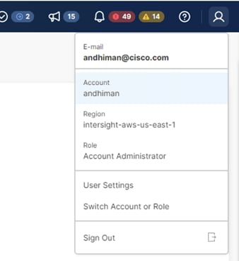
Step 4. On the Settings Screen, select API Keys and click Generate API Key.
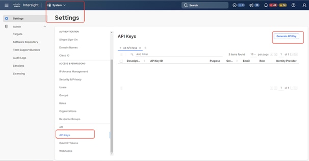
Step 5. From the Generate API Key screen, add a description to the Key. Select API Key for OpenAPI schema version 2 and click Generate.
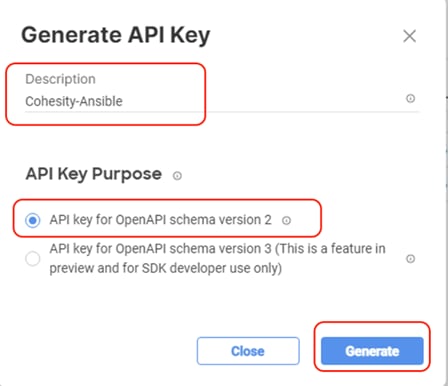
Step 6. Copy the API Key and save the secret Key to a location accessible from the system where the Ansible playbooks are executed.
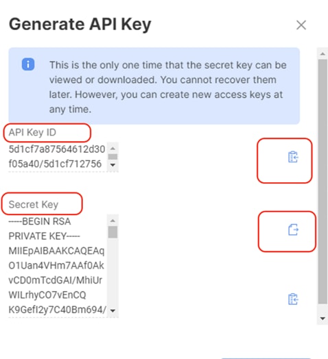
Step 7. Edit the group_vars/all.yml with the new API Key and SecretKey File location.
Procedure 1. Execute Ansible Playbook to create Pools
Note: In the event the IP Pool, MAC Pool and UUID Pools, are already created, you should not run create_pools.yml. Ensure you enter the correct name of these Pools in all.yml and proceed to creating Server Policies.
Step 1. Edit the variables group_vars/all.yml as defined in Table 19.
Step 2. Run the ansible-playbook ./create_pools.yml -i inventory.
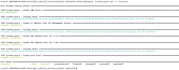
Step 3. When the Ansible playbook to create pools is executed successfully, confirm the created pools in Cisco Intersight.
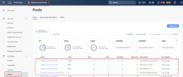
Procedure 2. Execute Ansible Playbook to create Server Policies
Note: In the event the IP Pool, MAC Pool and UUID Pools are already created, do not run create_pools.yml. Make sure to enter the correct name of these pools in all.yml and proceed to creating Server Policies.
Step 1. Edit the variables group_vars/all.yml as defined in the table above. Ignore if the file is already updated.
Step 2. Run ansible-playbook ./create_server_policies.yml -i inventory.
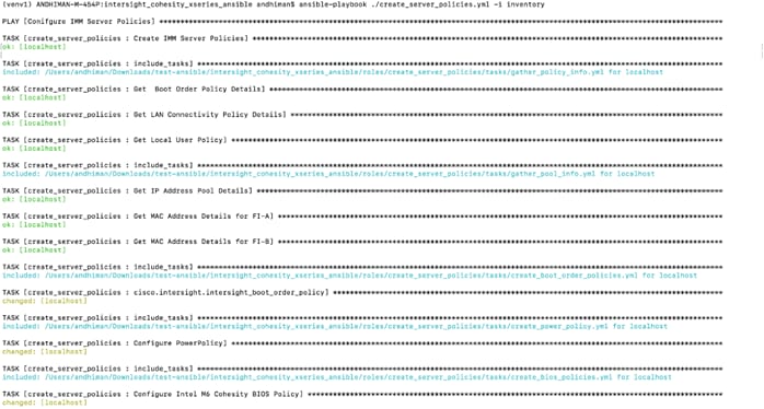
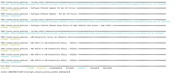
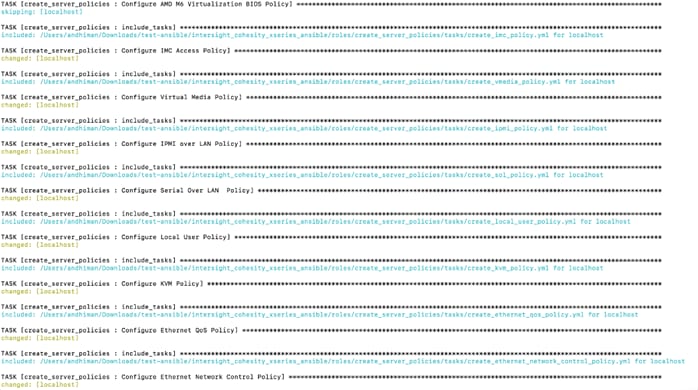
Step 3. When the Ansible playbook to create Server Policies is executed successfully, confirm the created Polices in Cisco Intersight.
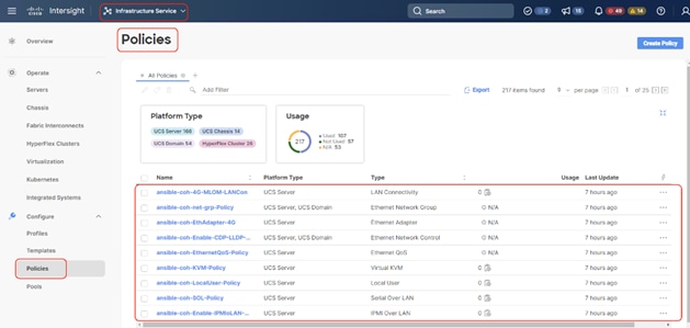
Procedure 3. Execute Ansible Playbook to create Server Profile Template for Cohesity X210c nodes
Step 1. Edit the variables group_vars/all.yml as defined in Table 19. Ignore if the file is already updated.
Step 2. Run ansible-playbook ./create_server_policies.yml -i inventory.
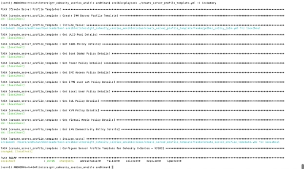
Step 3. Verify the created Server Profile Template on Cisco Intersight Dashboard.

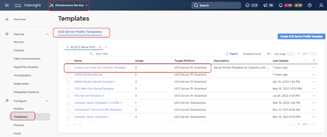
Install Cohesity on Cisco UCS X210c Nodes
Cohesity Data Cloud can be installed on Cohesity certified Cisco UCS X210c nodes with one of two options:
● Install OS through Intersight OS installation.
This allows installing the Cohesity Data Cloud operating System through Cisco Intersight. You are required to have an Intersight Advantage license for this feature. The operating system resides on a local software repository as an OS Image Link configured in Cisco Intersight. The repository can be a HTTTPS, NFS or CIFS repository accessible through the KVM management network. This feature benefits in the following ways:
◦ It allows the operating system installation simultaneously across several Cisco UCS X210c nodes provisioned for the Cohesity Data Cloud.
◦ It reduces Day0 installation time by avoiding mounting the ISO as Virtual Media on the KVM console for each node deployed for Cohesity Data Cloud on each Cisco UCS X210c node.
● Install the OS by mounting ISO as virtual Media for each node.
Derive and Deploy Server Profiles
Procedure 1. Derive and Deploy Server Profiles
In this procedure, Server Profiles are derived from Server Profile Template and deployed on Cisco UCS X210C nodes certified for the Cohesity Data Cloud.
Note: The Server Profile Template specific to the Cohesity Data Cloud were configured in the previous section. As mentioned, the Server Profile Template can be created through the Cohesity Ansible Automation playbook or through the Manual creation of Server Policies and Server Template.
Step 1. Select Infrastructure Service, then select Templates and identify the Server Template created in the previous section.
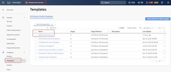
Step 2. Click the … icon and select Derive Profiles.
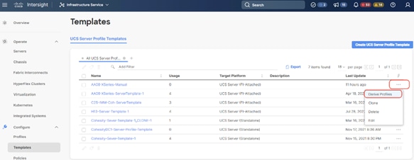
Step 3. Identify and select the Cisco UCS X210c nodes for Server Profile deployment and click Next.
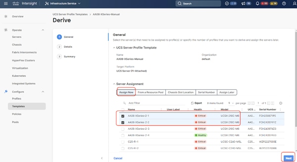
Step 4. Select organization (default in this deployment), edit the name of Profiles if required and click Next.
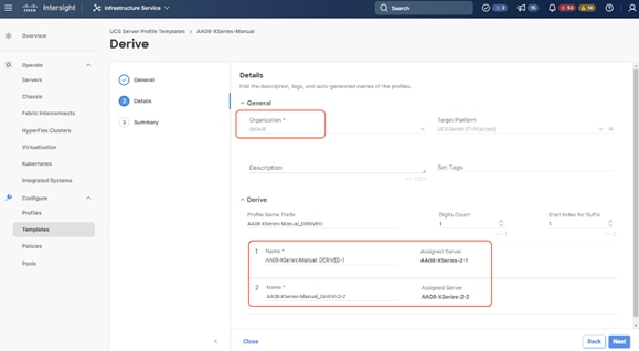
Step 5. All Server policies attached to the template will be attached to the derived Server Profiles. Click Derive.
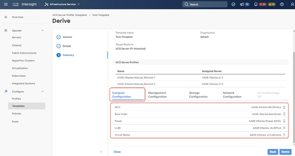
Step 6. The Server Profiles will be validated and ready to be deployed to the Cisco UCS X210c nodes. A “Not Deployed” icon will be displayed on the derived Server Profiles.
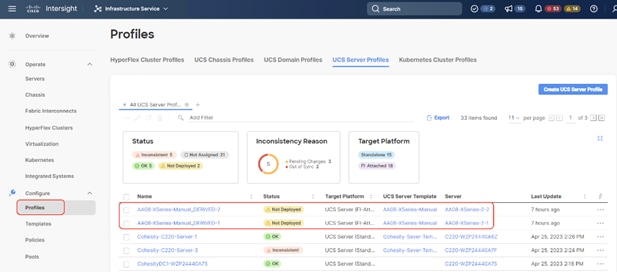
Step 7. Select the Not Deployed Server Profiles, click the … icon and click Deploy.
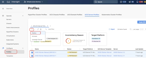
Step 8. Enable Reboot Immediately to Activate and click Deploy.
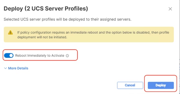
Step 9. Monitor the Server Profile deployment status and ensure the Profile deploys successfully to the Cisco UCS X210C node.
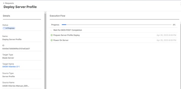
Step 10. When the Server Profile deployment completes successfully, you can proceed to the Cohesity Data Cloud deployment on the Cisco UCS X210C nodes.
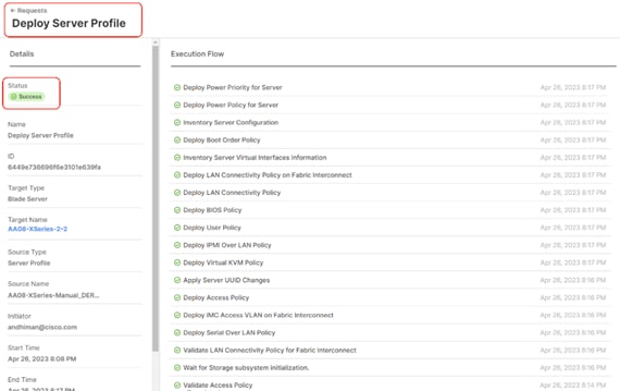
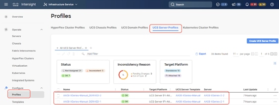
Step 11. Access KVM with KVM username > kvm-user and password > <<as configured in local user policy>>, and make sure the node is accessible.
Step 12. Virtual KVM can be accessed by directly launching from Cisco Intersight (Launch vKVM) or access the node management IP.
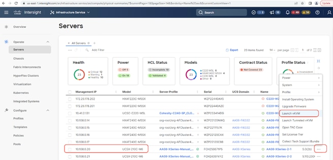
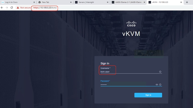
Install OS through Cisco Intersight
Procedure 1. Install Cohesity Data Cloud through Cisco Intersight OS Installation feature
This procedure expands on the process to install the Cohesity Data Cloud operating system through the Cisco Intersight OS installation feature.
Note: This feature is only supported with the Intersight Advantage Tier License.
Note: Make sure the certified Cohesity Data Cloud ISO is available from a local repository, for example an HTTPS/NFS/CIFS server. This is a one-time process for each version of the Cohesity Data Cloud ISO.
Step 1. Login to Cisco Intersight and click System.
Step 2. Click Software Repository and click the OS Image Links tab.
Step 3. Click Add OS Image Link.
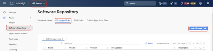
Step 4. Add the location of the Cohesity Data Cloud ISO (NFS/CIFS or HTTPS server) and click Next.
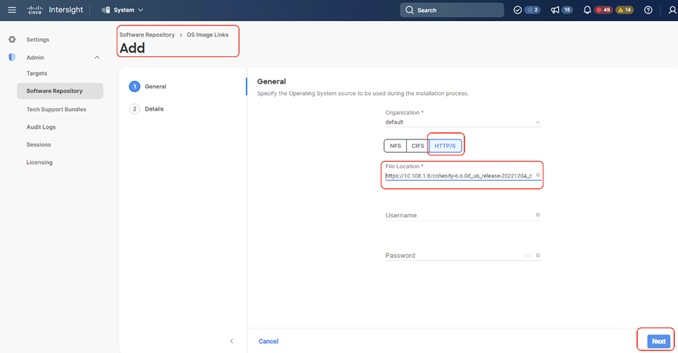
Step 5. Enter a name for the Repository, for the Vendor enter CentOS, and for the Version enter CentOS7.9. Click Add.
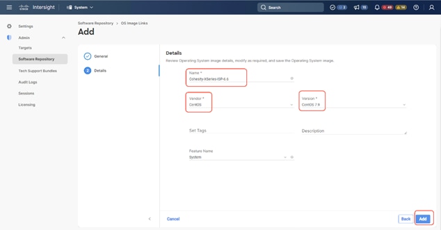
Step 6. Make sure the OS Repository is successfully created in Cisco Intersight.
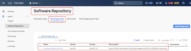
Step 7. From Cisco Intersight, click Infrastructure Service, then click Servers, and select the Cisco UCS X210C nodes ready for the Cohesity Data Cloud installation.
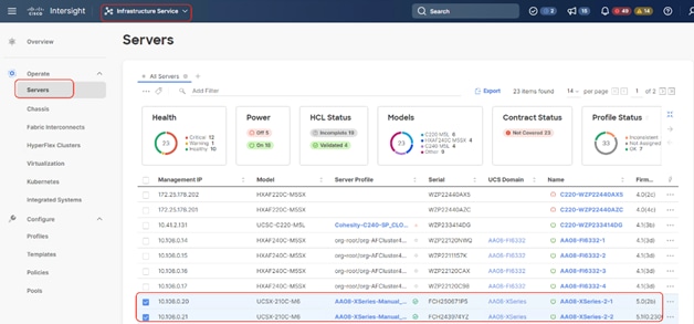
Step 8. Click the … and select Install Operating System.
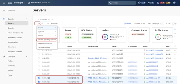
Step 9. Make sure the servers are already selected and click Next.
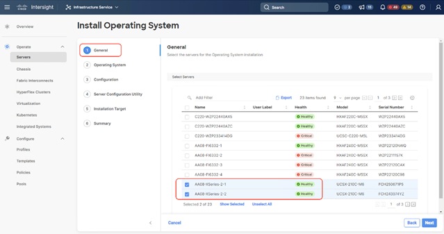
Step 10. Select the Operating System repository which was previously created with the Cohesity Data Cloud ISO and click Next.
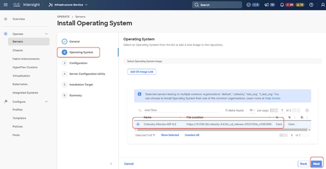
Step 11. From Configuration, click Embedded and click Next (the OS configuration file is already part of Cohesity ISO).
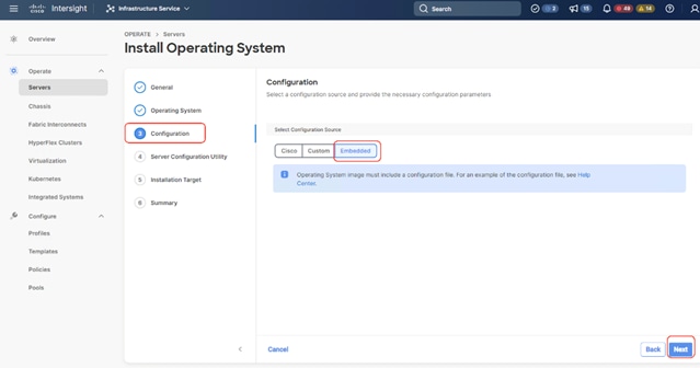
Step 12. Click Next.
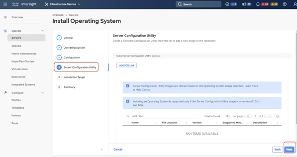
Step 13. Click Next from the Installation target. Cohesity ISO automatically identifies the Installation target as the 2x M.2 internal drives configured in the Boot Order Server Policy.
Step 14. Verify the summary and click Install.
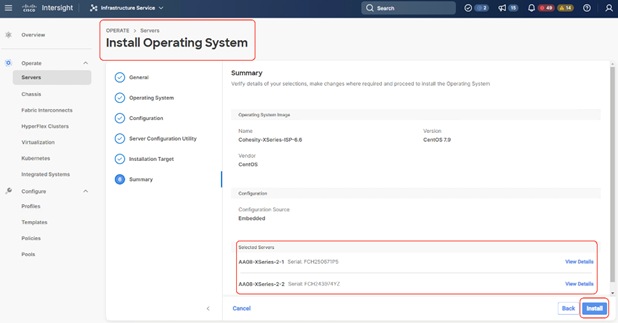
Step 15. Accept the warning for overwriting the existing OS image on the node and click Install.
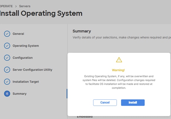
Step 16. Monitor the OS installation progress and wait for completion. Depending on the network bandwidth between the node management network and the repository network, it can take up to 45 minutes for the OS installation to complete.
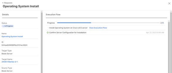
Step 17. Since this is an embedded installation without the Cisco Server Configuration utility, Cisco Intersight displays the OS installation completion in about five minutes. Open a virtual KVM session and monitor the Cohesity OS install progress. Since this is an automated install, you are not required to provide any inputs on the virtual KVM screen. The OS installation progress is shown below:
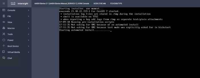
Install OS through Virtual Media
Procedure 1. Install Cohesity Data Cloud through Virtual Media
This procedure expands on the process to install the Cohesity Data Cloud operating system through virtual media. You need to open a virtual KVM session for each node. Virtual KVM session can be accessed through Cisco Intersight or logging into node management IP assigned during Server Profile deployment.
Note: If you are installing the OS through virtual media and it times out, please use a different browser such as Mozilla Firefox.
Step 1. Login to virtual KVM, click Virtual Media and click vKVM-Mapped DVD.
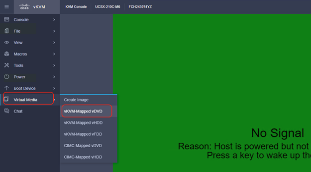
Step 2. Select the Cohesity Data Cloud ISO from your local file system and click Map Drive.
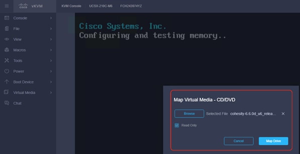
Step 3. Click Power and then click Reset System to reset the power cycle on the node. The Cohesity ISO automatically loads (with virtual Media having highest priority in Boot Order Server Policy).
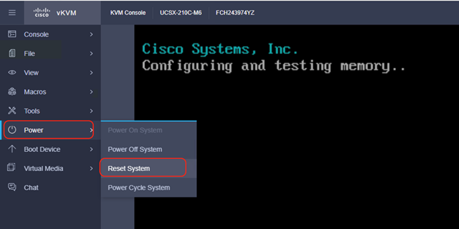
Step 4. The ISO automatically identifies the drives to install the Cohesity ISO; the OS installation completes in about 45 minutes.
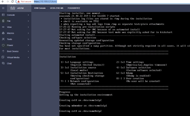
Step 5. Repeat this procedure for all Cisco UCS X210c nodes to be configured for the Cohesity Data Cloud cluster.
This section elaborates on the configuration of the Cohesity Data Cloud on Cisco UCS X-Series Modular System. The existing deployment is deployed with three (3) Cisco UCS X210c nodes with each node configured with both compute and All NVMe storage.
Note: Make sure the Data Cloud ISO is installed on each Cisco UCS X210c node.
Note: The network bonding mode on the Cohesity operating systems (CentOS 7.9)_ with Cisco UCS X-Series or Cisco UCS Fabric Interconnect Managed C-Series servers does not support bond mode 4. For reference, go to: https://www.cisco.com/c/en/us/support/docs/servers-unified-computing/ucs-b-series-blade-servers/200519-UCS-B-series-Teaming-Bonding-Options-wi.html)
The Data Cloud Cluster configuration is a two-step process:
● Initial network configuration on 1x Cisco UCS X210c node
● Cluster configuration across all Cisco UCS X210c nodes
Procedure 1. Initial Network Configuration on 1x Cisco UCS X210c Node
In this procedure, any one of the Cisco UCS X210 nodes are accessed through the virtual KVM and the initial operating system network is configured.
Step 1. Login to Cisco Intersight, click Infrastructure Service and click Servers. Identify the Cisco UCS X210c nodes installed with the Cohesity Data Cloud ISO.
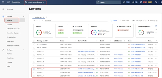
Step 2. Select the first node and launch the virtual KVM.
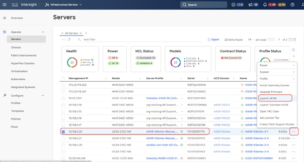
Step 3. Make sure the Cohesity Data Cloud is installed on the node.
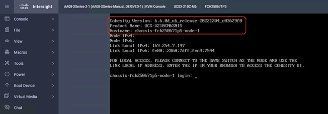
Step 4. Login to the node with the username <cohesity> and password <received from Cohesity>.
Step 5. Edit the network configuration through the network configuration script:
sudo ~/bin/network/configure_network.sh.
Step 6. Select option 2 Configure IP Address on interface.
Step 7. Select default interface bond0.
Step 8. Enter the IP Address, Interface Prefix, and Gateway.
Step 9. Select the default MTU to 1500.
Step 10. Select Y/Yes to make the interface active.
Step 11. Quit the configure_network script by entering option 12.
Step 12. Test the network is working properly by pinging the default gateway. You can also verify the IP address configuration by issuing the following command:
ip addr
Step 13. When network is configured, make sure the OS IP is reachable.
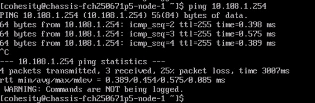
Procedure 1. Cohesity Cluster Configuration Across all Cisco UCS X210c Nodes
The initial setup of the Cohesity cluster is done through the configuration webpage, which is now accessible on the first node, at the IP address which was configured in the previous steps. Prior to beginning the initial cluster configuration, make sure that all Cohesity nodes which are to be included in the cluster have completed their initial software installation, and are fully booted. Additionally, make sure that all necessary IP addresses for all interfaces are known and assigned, and the DNS round-robin entries have been created.
Step 1. In a web browser, navigate to the IP address of the first Cohesity node, which was configured in the previous steps. For example: http://10.108.1.32
Step 2. Accept any SSL warnings or errors due to the default self-signed certificate on the server and proceed to the Cohesity Dashboard login screen.
Step 3. Log into the Cohesity Dashboard webpage using the following credentials:
● Username: admin
● Password: <password>
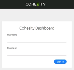
Step 4. When the Start Initial Cluster Setup screen appears, make sure that the number of nodes detected matches the number of servers you intend to install for this cluster. Click Get Started.
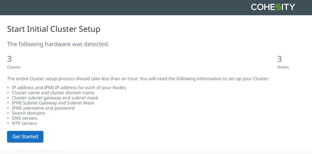
Step 5. Select the nodes to add to this initial cluster, then click Select Nodes.
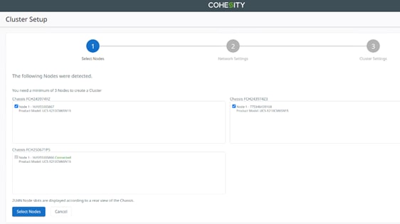
Step 6. Enter the OS IP determined for each node, do not add any IPMI IP.
Note: With Cohesity release 6.6 or later, all Cisco UCS servers connected to Cisco UCS Fabric Interconnects do not require any IPMI configuration. Keep the IPMI Field blank and delete any pre-existing IPMI IP during cluster creation.
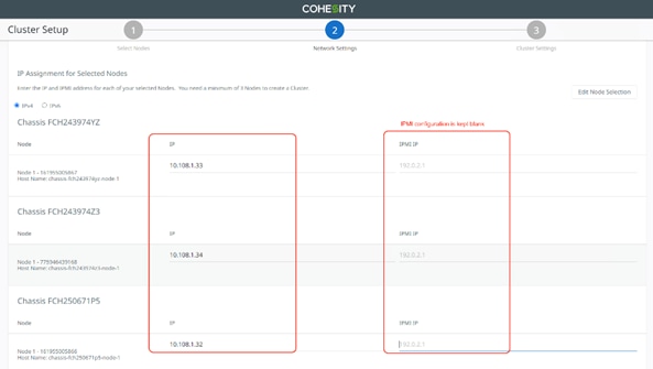
Step 7. Select the nodes to add to this initial cluster, then click Select Nodes.

Step 8. Enter the Cluster Subnet, Gateway, DNS, NTP, Virtual IP and FQDN details and click Create Cluster.
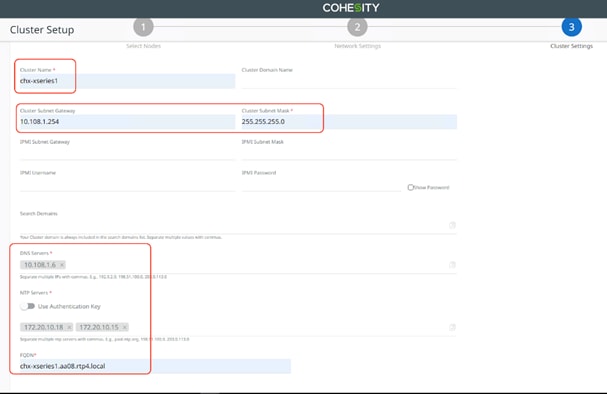
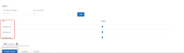
Step 9. When the cluster is created, login with FQDN and register the cluster to Cohesity Helios.
Step 10. Confirm the 3x Cisco UCS X210c nodes are configured for the new Cohesity Data Cloud cluster.
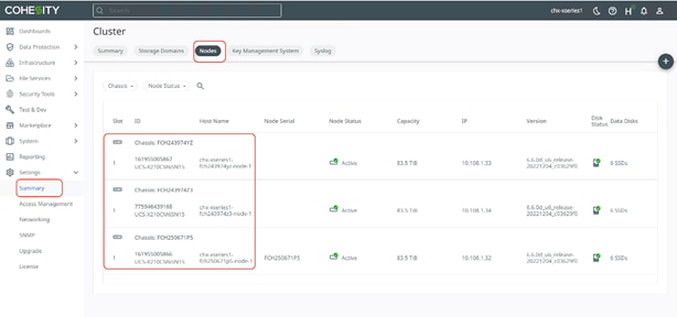
Cluster Expansion and Firmware Upgrades
This chapter contains the following:
● Upgrade Firmware and Software
This section details how you can expand the existing cluster deployed on Cisco X-Series modular system. Each Cisco UCS X-Series modular system accommodates up to eight (8) All NVMe Cisco UCS X210c nodes, providing compute and storage. You can add a new Cisco UCS X210c node in the existing Cisco UCS X-Series chassis, derive a Server Profile from existing Template, install the Cohesity OS from Cisco Intersight, and expand the cluster in Cohesity Helios.
This does not require any additional cabling or network configuration. In the event you want to expand to additional Cisco UCS X-Series chassis, you can add a new Cisco UCSX-Series Chassis to the existing Cisco UCS Fabric Interconnect, clone the chassis and server profile, and attach to the new Cisco UCS X-Series chassis. IT requires minimal effort to expand both compute and storage.
Derive and Deploy Server Profile
Procedure 1. Derive and Deploy Server Profile to New Node
Note: Skip this step if you already have a Cisco Intersight account.
Step 1. Go to https://intersight.com/, click Infrastructure Service and click Server. Identify the new Cisco UCS X210c node provisioned for the existing Cohesity Data Cloud cluster expansion.
Note: This Cisco UCS X210c node does not have a Server Profile attached to it.
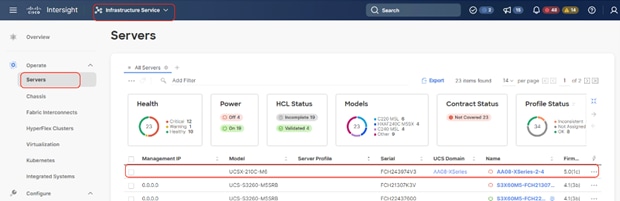
Step 2. Click “… “, select Profile and Derive Profile from the template.
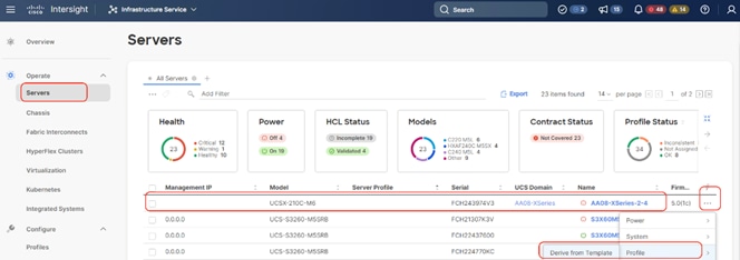
Step 3. The Cisco UCS X210c node is displayed, click Next.
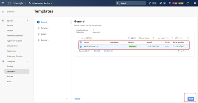
Step 4. Select the Server Profile template created to deploy the Cisco UCS X210c node for the Cohesity Data Cloud cluster and click Next.
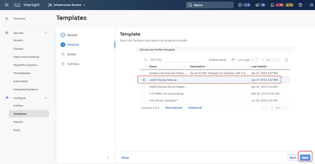
Step 5. Rename the Derive profile and click Next.
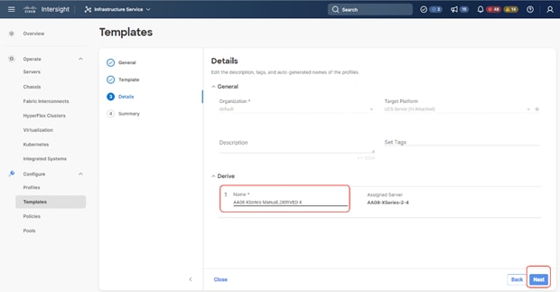
Step 6. Verify the policies and click Derive.
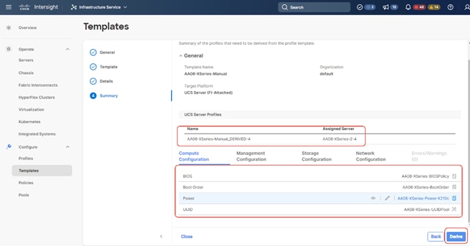
Step 7. When the Sever Profile is derived, go to the Servers tab, identify the Profile displayed as “Not Deployed,” click the “…” and select Deploy.
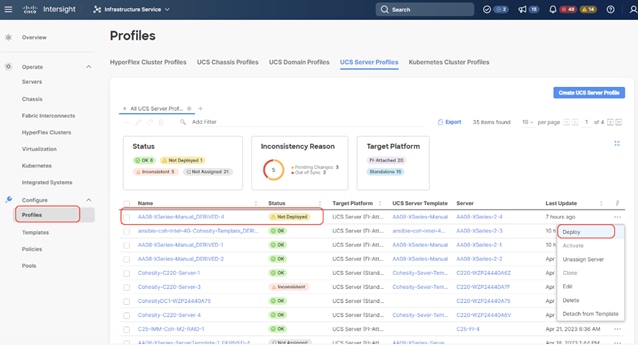
Step 8. On the Deploy Profile confirmation screen, enable Reboot Immediately to Activate and click Deploy.
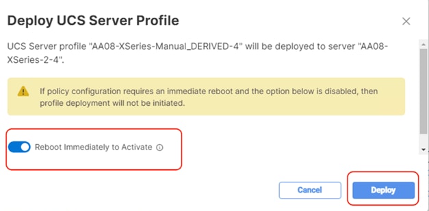
Step 9. When the profile is successfully deployed, install the OS using Cisco Intersight, provided in section Cohesity Data Cloud Node Configuration on Cisco UCS X210c Nodes. The screenshot below displays on the Cohesity Data Cloud OS deployed on the new Cisco UCS X210c node:
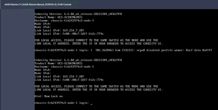
Procedure 1. Expand existing Cluster through Cohesity Helios
When the new Cisco X210c node is configured with the Cohesity Data Cloud OS, the Cohesity Cluster is expanded to add the Cisco UCS X210c node. This process expands the compute and storage on the Cohesity Data Cloud Cluster.
Step 1. Access the Cohesity Data Cloud Cluster dashboard. Go to Summary > Nodes and click the + sign and select Add Node.
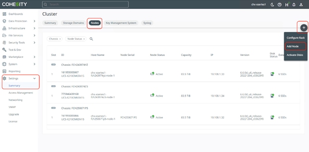
Step 2. The Cohesity Data Cloud cluster automatically identifies the new node. Confirm the serial number of the node, which was configured for the cluster expansion, select the node, and click Next.
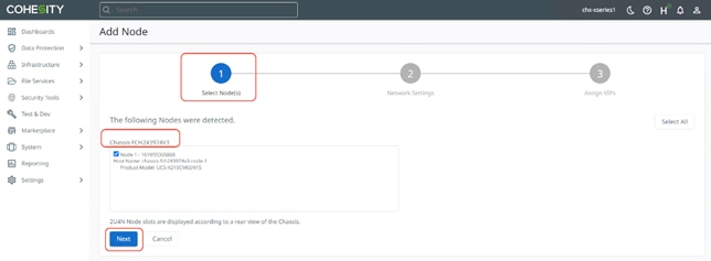
Step 3. Add the available Node IP and click Next.
Step 4. Add the Virtual IP as configured on DNS and click Finish.
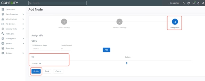
Step 5. The Cohesity Data Cloud Cluster is expanded from three to four nodes of All NVMe Cisco UCS X210c server. It takes some time to assimilate the All NVMe drives of the new Cisco UCS X210c node to the existing Cohesity Data Cloud Cluster.
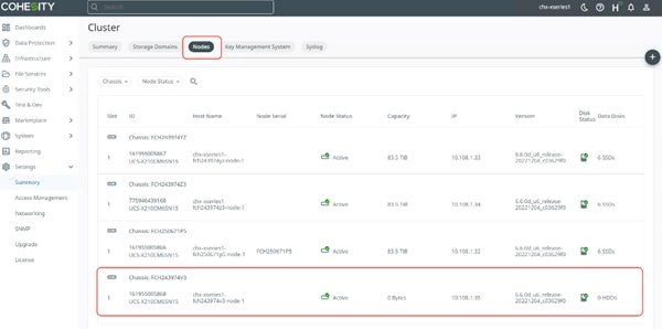
Upgrade Firmware and Software
Note: With the Intersight SaaS Management platform, the server firmware upgrade does not require you to download any firmware bundles to a local repository. When the suggested firmware upgrade request is issued, it automatically downloads the selected firmware and starts the upgrade process.
For detailed instructions to perform firmware upgrades, see Firmware Management in Intersight
Firmware for Cisco UCS X-Series Modular System with the Cohesity Data Cloud can be upgraded for the following main use cases:
● Upgrade Cisco UCS X-Series X210c node firmware in combination with software upgrades for the Cohesity Data Cloud. Cohesity non-distributive upgrades manage the sequential server reboot, allowing upgrades of Cisco UCS X210c node firmware during a Cohesity software upgrade. Because each node is upgrading sequentially, the Cohesity Cluster upgrade time increases by about 25 to 30 minutes per Cohesity node.
● Upgrade Cisco UCS X-Series X210c node independent of the Cohesity Data Cloud software upgrades. In this process, you need to manually reboot the Cisco UCS X210 node and verify that the Cohesity node is back online after the server firmware upgrade. Verify that each node is rebooted serially, and that the first node comes back online and joins the Cohesity cluster before initiating a reboot on the second node. This process can also be done in parallel across all Cisco UCS X210c nodes but requires maintenance windows for Cohesity Cluster downtime.
Note: Prior to upgrading Cisco UCS X210C node firmware, you are required to upgrade the Cisco Fabric Interconnect and Cisco UCS X-9108 IFM modules.
To successfully upgrade the Cisco UCS Fabric Interconnect and IO module firmware, see: https://intersight.com/help/saas/resources/Upgrading_Fabric_Interconnect_Firmware_imm#procedure
Note: During the upgrade of the Intersight Managed Fabric Interconnect, the fabric interconnect traffic evacuation is enabled by default. The fabric interconnect traffic evacuation evacuates all traffic that flows through the fabric interconnect from all servers attached to it, and the traffic will fail over to the peer fabric interconnect for fail over vNICs with no disruptions in the network.
Upgrade Fabric Interconnect and Intelligent Fabric Module
Procedure 1. Upgrade Cisco UCS Fabric Interconnect and Cisco UCSX 9108 IFM Firmware
This procedure expands on the high-level procedure to upgrade firmware of the Cisco UCS Fabric Interconnect in Intersight Managed Mode (IMM). For more details, go to: https://intersight.com/help/saas/resources/Upgrading_Fabric_Interconnect_Firmware_imm#before_you_begin
Note: During the firmware upgrade of Cisco UCS Fabric interconnects, the Cisco UCSX 9108 IFM modules installed in the Cisco UCS X-Series chassis will be automatically upgraded.
Step 1. Login to https://Intersight.com, click Infrastructure Service, then click Fabric Interconnects, and select the Fabric Interconnect Pair (IMM) . Click “…” and select Upgrade Firmware.
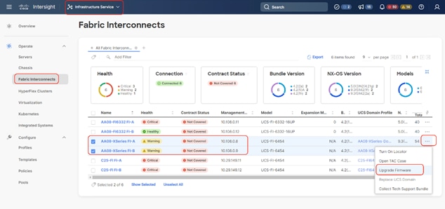
Step 2. Click Start and from Upgrade firmware make sure the UCS Domain Profile is selected and click Next.
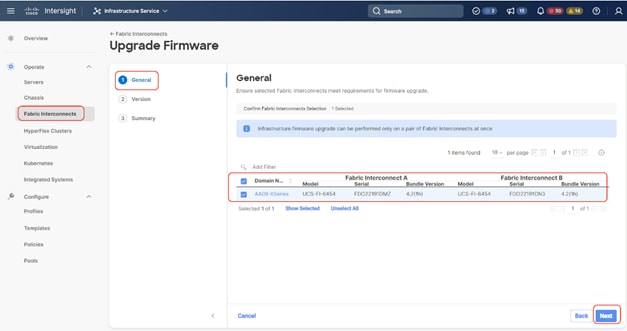
Step 3. Select the recommended Firmware release (currently 4.2(3d)). By default, the upgrade enables the Fabric Interconnect traffic evacuation. Use Advanced Mode to exclude the Fabric Interconnect traffic evacuation.
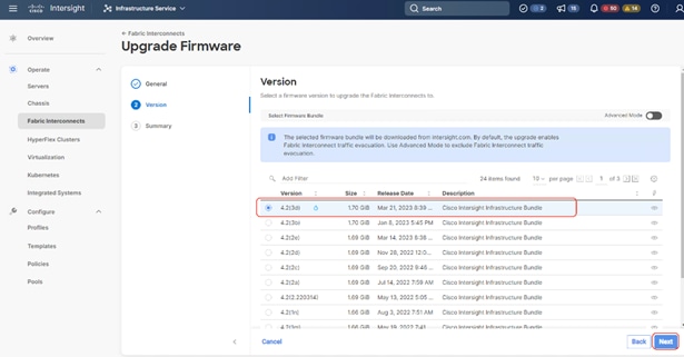
Step 4. On the Summary page, confirm the firmware to be upgraded and click Upgrade.
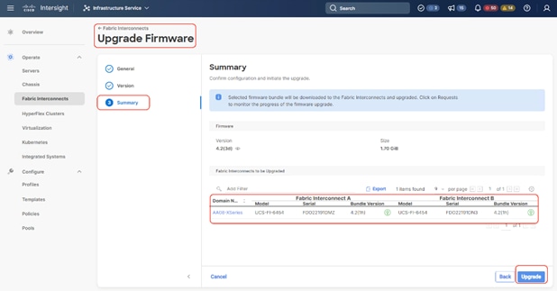
Step 5. Monitor the upgrade process and wait for it to complete. 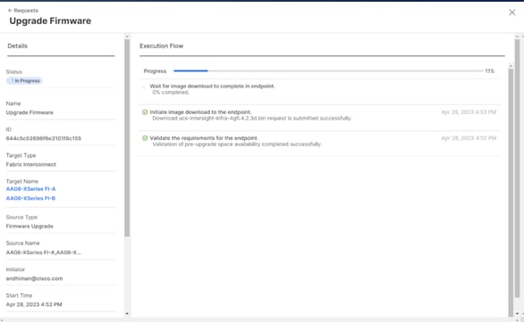
Step 6. When the Firmware downloads, acknowledge the Fabric Interconnect B upgrade, and click Continue.
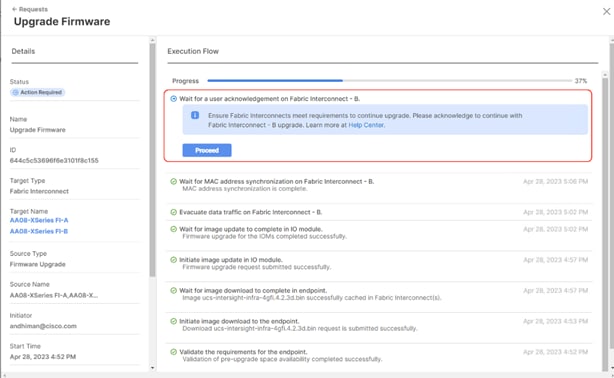
Step 7. When Fabric Interconnect -B is upgraded, acknowledge the Fabric Interconnect – A upgrade.
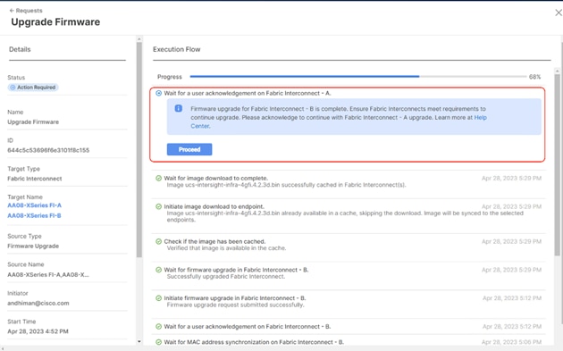
Step 8. Make sure the Firmware upgrade completed successfully.
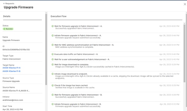
Step 9. Verify the firmware upgraded on the Cisco UCS Fabric Interconnect and Cisco UCSX-9108 IFM modules.
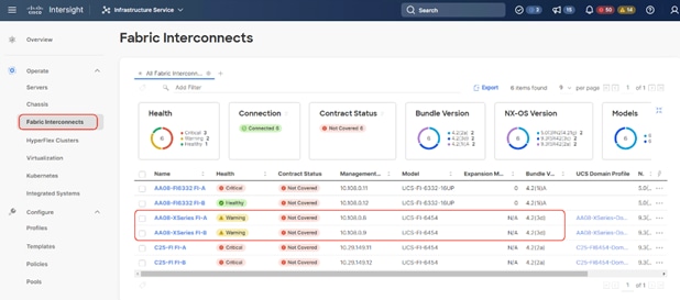
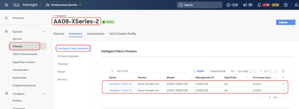
Rolling Upgrades (Node Firmware and Cohesity software)
Procedure 1. Upgrade Cisco UCS X210C Node Firmware with Cohesity Data Cloud Software Upgrade
This procedure expands on the procedure to upgrade the firmware of Cisco UCS X210C Cohesity certified nodes with Cohesity Data Cloud Cluster software upgrade.
Note: Before starting the upgrade procedure, make sure the recommended Cisco UCS X210C firmware is compatible with the Cohesity Data Cloud version.
Step 1. Login to https://Intersight.com, click Infrastructure Service, then click Servers. Select the Cisco UCS X210c nodes that are part of the Cohesity Data Cloud cluster. Click the … icon and select Upgrade Firmware.
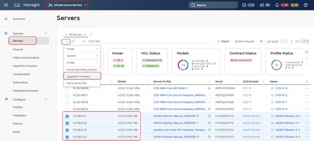
Step 2. Make sure all Cisco UCS X210C nodes are selected for upgrade. Click Next.

Step 3. Select the recommended Server Firmware version and click Next. At the time of publishing this guide, the suggested firmware was 5.1(0.230054). If the firmware upgrade does not require drive firmware updates, select Advanced Mode, and check the Exclude Drive option.
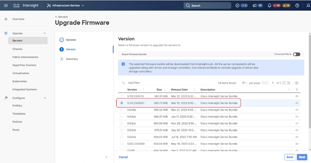
Step 4. Click Upgrade.
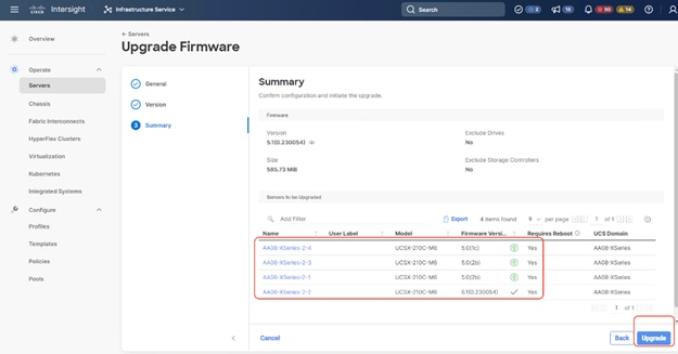
Step 5. Retain the Reboot Immediately to Begin Upgrade option as unselected. When the firmware is mounted and the reboot server message appears, start upgrading the Cohesity Cluster software which will ensure the serial reboots of each node (rolling reboots) and avoid any disruption of operations on Cohesity Data protection services.
Step 6. Click Upgrade.
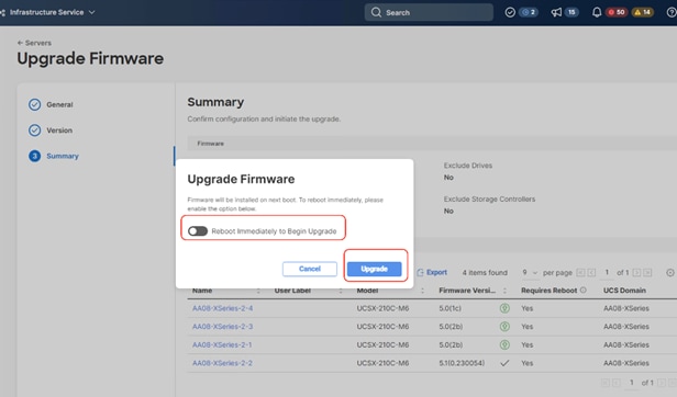
The Firmware image is downloaded to the end point and staged to the respective node:
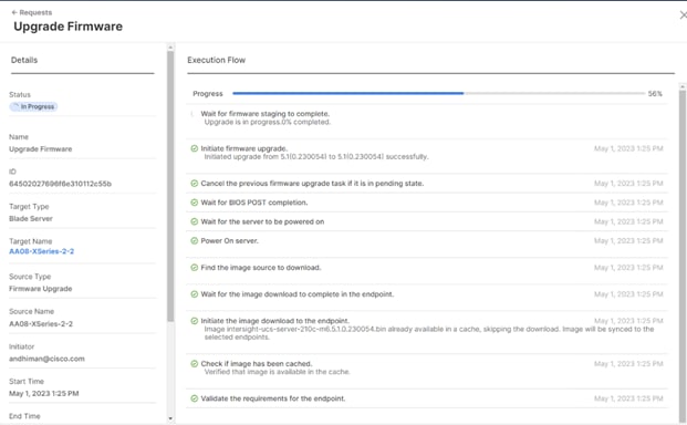
Step 7. When the Server Power cycle option is displayed, close the message, and do not click Proceed. Before proceeding to the next step, make sure all nodes are at this stage.
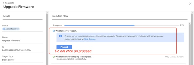
Step 8. Login to the Cohesity Data Cloud Cluster dashboard and click Settings. Click Upgrade.
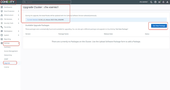
Step 9. Click Get New Package and upload the recommended Cohesity Data Cloud upgrade package. Click Upload and Upgrade.
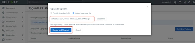
Step 10. This step of the upgrade process will take some time, about 20-30 minutes per node when the Cisco UCS X210c nodes are rebooted and upgraded serially. It will take an additional 2-hours for the four node Cohesity Cluster rolling upgrade of the server firmware.
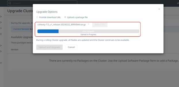
Rebooting the node initiated through the Cohesity Data Cloud upgrade and the Cisco UCS X210c firmware update after its reboot is shown below:
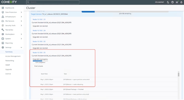
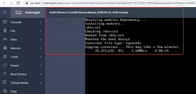
Step 11. You can also monitor the firmware upgrade status of the node with Cisco Intersight in Progress Request.
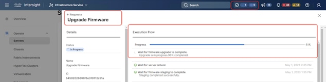
The details of the firmware and software upgrade completing the first Cisco UCS X210C node and the beginning of the upgrade procedure for the second Cisco UCS X210C node initiated through the Cohesity Data Cloud is shown below:
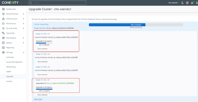
Step 12. When the upgrade completes, confirm the upgraded versions for the Cohesity Data Cloud and Cisco UCS X210C node firmware.
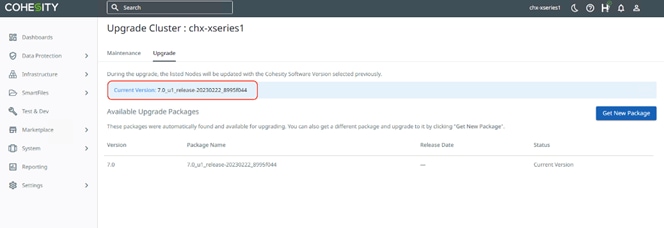
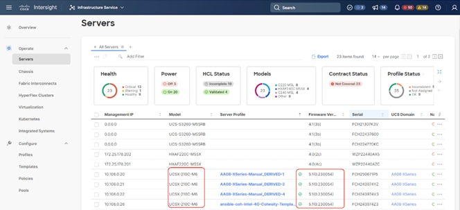
Upgrade Node Firmware (independent of the Cohesity Cluster)
Procedure 1. Upgrade Cisco UCS X210C Node Firmware independent of Cohesity Data Cloud Upgrades
Note: This procedure expands on the procedure to upgrade the firmware of only Cisco UCS X210c Cohesity certified nodes. The Cohesity Data Cloud software upgrade is not part of this procedure.
Note: Before starting the upgrade procedure, make sure the recommended Cisco UCS X210c firmware is compatible with the Cohesity Data Cloud version.
Note: Since the Cisco UCS X210c node firmware upgrade requires a reboot. please initiate support of Cohesity to shut down the Cohesity Data Cloud cluster during the maintenance window.
This procedure is utilized in three key circumstances.
● Only the Cisco UCS X210C node firmware requires an upgrade.
● You are comfortable with having a maintenance window for the Cohesity Data Cloud cluster downtime.
● Since the Rolling upgrade adds up to 20-30 minutes per node, it could be time consuming for Cohesity Data Cloud cluster with several nodes. In this case, you can initiate a node reboot from Cisco Intersight and upgrade the Cisco UCS X210C node firmware in parallel to all nodes. This requires downtime for Cohesity Data Cloud and can only be initiated in a maintenance window.
Step 1. Login to https://intersight.com, click Infrastructure Service, then click Servers. Select the Cisco UCS X210C nodes that are part of the Cohesity Data Cloud cluster. Click the … icon and select Upgrade Firmware.
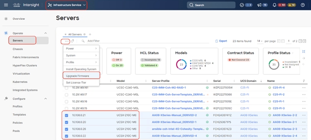
Step 2. Make sure all Cisco UCS X210C nodes are selected for upgrade. Click Next.
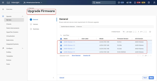
Step 3. Select the recommended Server Firmware version and click Next. At the time of publishing this guide, the suggested firmware was 5.1(0.230054). If the firmware upgrade does not require drive firmware updates, select Advanced Mode, and check the ‘Ede Drive option.

Step 4. Click Upgrade.

Step 5. Select the Reboot Immediately to Begin Upgrade option. This initiates the firmware upgrade across all Cisco UCS X210c Cohesity certified nodes.
Step 6. When the firmware is mounted and the reboot server message appears, start upgrading the Cohesity Cluster software which ensures the serial reboots of each node (rolling reboots). This avoids any disruption of operations with the Cohesity data protection services.
Step 7. Click Upgrade.
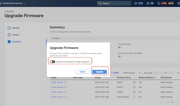
The Firmware image is downloaded to the end point and staged to the respective node:

Step 8. When the Server Power cycle option is displayed, close the message, and click Proceed.
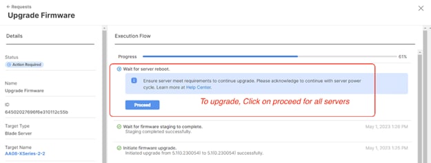
Step 9. Confirm the firmware upgrade across all Cisco UCS X210c nodes is complete.
Step 10. When the firmware across all Cisco UCS X210c nodes are upgraded, restart the Cohesity Data Cloud Cluster.
Cohesity Certified Cisco UCS Nodes
This solution utilizes 4x Cisco UCS X210c All NVMe nodes configured on the Cisco UCS X-Series Modular System. Along with this configuration, Cisco and Cohesity have certified solutions with different capacity points available on Cisco UCS C-Series Rack Servers and Cisco UCS S3260 Storage Servers. This allows you to select your configuration based on key characteristics such as:
● Total Capacity
● Workload configurations such as Data Protection and File Services
● Performance requirements based on Cisco X-Series Modular System with All NVMe Cisco UCS X210c nodes, Cisco UCS C220 M6 All Flash or Cisco UCS C240 M6 LFF HDD (12 and 16 drives) configurations.
● Single node deployments for Remote offices and Branch offices (ROBO)
● Cohesity SmartFiles solution with Cisco UCS S3260 dual node configuration
Table 20 lists the Cohesity-certified nodes on Cisco UCS Platform.
Table 20. Cohesity Certified Cisco UCS Nodes
| Solution Name |
Cisco UCS Platform |
Capacity per Node |
Caching SSDs/NVMe per Node |
| Cohesity X-Series Al NVMe nodes |
Cisco UCS X9508 platform |
91.8 TB |
|
| Cohesity-C240 M6 LFF-Nodes |
Cisco UCS C240 M6 LFF Rack Server with 12 and 16 drive options |
48 TB |
3.2 TB |
| 64 TB |
3.2 TB |
||
| 96 TB |
6.4 TB |
||
| 128 TB |
6.4 TB |
||
| 144 TB |
6.4 TB |
||
| 192 TB |
6.4 TB |
||
| 216 TB |
12.8 TB |
||
| 288 TB |
12.8 TB |
||
| Cohesity-C220 M5-ROBO-8TB-and-16TB-Nodes |
Cisco UCS C220 M5 LFF Rack Server |
8 TB |
1920 GB |
| 16 TB |
1920 GB |
||
| Cohesity-C220-All-NVMe-Nodes |
Cisco UCS C220 M6 All NVMe Rack Server |
76 TB |
|
| Cohesity-S3260-210TB-294TB-420TB-588TB-704TB-768TB-Node |
Cisco UCS S3260 M5 Storage Server |
210 TB |
12.8 TB |
| 294 TB |
12.8 TB |
||
| 420 TB |
12.8 TB |
||
| 588 TB |
12.8 TB |
||
| 704 TB |
12.8 TB |
||
|
|
Cisco UCS S3260 M5 dual node Storage Server (SmartFiles) |
768 TB |
25.6 TB |
| 384 TB ** |
12.8 TB |
Note: **384 TB half populated Cisco UCS S3260 chassis can only be purchased in conjunction with a dual node 768TB configuration.
Anil Dhiman, Technical Leader, Technical Marketing Engineering, UCS Solutions, Compute & Networking Group, Cisco Systems, Inc.
Anil Dhiman has nearly 20 years of experience specializing in data center solutions on Cisco UCS servers, and performance engineering of large-scale enterprise applications. Over the past 11 years, Anil has authored several Cisco Validated Designs for enterprise solutions on Cisco data center technologies. Currently, Anil's focus is on Cisco’s portfolio of hyperconverged infrastructure and data protection solutions.
Damien Philip, Principal Solutions Architect, Cohesity
For their support and contribution to the design, validation, and creation of this Cisco Validated Design, the authors would like to thank:
● Rohit Mittal, Product Manager, Cisco Systems, Inc.
● Francesca Harbert, Director, Cisco Global Alliance, Cohesity
● Eleonor Lee, Senior Product Marketing Manager - Alliances Solutions
This appendix is organized into the following sections:
● Appendix A – Bill of Materials
● Appendix B – References Used in Guide
● Appendix C – Known Issues and Workarounds
● Appendix D – Recommended for You
Appendix A – Bill of Materials
Table 21 provides an example the Bill of Materials used for four (4) node Cohesity DataPlatform cluster deployed on a single Cisco UCS X-Series chassis, along with a pair of Cisco Fabric Interconnects, used in the testing and reference design described in this document.
Table 21. Cohesity FileServices (4 nodes) on Cisco UCS Bill of Materials
| Cisco X-Series estimate (4 All NVMe nodes) for Cohesity DataPlatform |
|||
| 1.0 |
UCSX-M6-MLB |
UCSX M6 Modular Server and Chassis MLB |
1 |
| 1.1 |
DC-MGT-SAAS |
Cisco Intersight SaaS |
1 |
| 1.1.1 |
DC-MGT-SAAS-EST-C |
Cisco Intersight SaaS - Essentials |
4 |
| 1.1.2 |
SVS-DCM-SUPT-BAS |
Basic Support for DCM |
4 |
| 1.1.3 |
DC-MGT-IMCS-1S |
IMC Supervisor - Advanced - 1 Server License |
4 |
| 1.1.4 |
DC-MGT-UCSC-1S |
UCS Central Per Server - 1 Server License |
4 |
| 1.2 |
UCSX-9508-U |
UCS 9508 Chassis Configured |
1 |
| 1.2.0.1 |
CON-OSP-UCSX95U8 |
SNTC-24X7X4OS UCS 9508 Chassis Configured |
1 |
| 1.2.1 |
UCSX-CHASSIS-SW |
Platform SW (Recommended) latest release for X9500 Chassis |
1 |
| 1.2.2 |
UCSX-9508-FSBK |
UCS 9508 Chassis Front Node Slot Blank |
4 |
| 1.2.3 |
UCSX-9508-CAK |
UCS 9508 Chassis Accessory Kit |
1 |
| 1.2.4 |
UCSX-9508-RBLK |
UCS 9508 Chassis Active Cooling Module (FEM slot) |
2 |
| 1.2.5 |
UCSX-9508-ACPEM |
UCS 9508 Chassis Rear AC Power Expansion Module |
2 |
| 1.2.6 |
UCSX-9508-KEY-AC |
UCS 9508 AC PSU Keying Bracket |
1 |
| 1.2.7 |
UCSX-210C-M6 |
UCS 210c M6 Compute Node w/o CPU, Memory, Storage, Mezz |
4 |
| 1.2.7.0.1 |
CON-OSP-UCSX210C |
SNTC-24X7X4OS UCS 210c M6 Compute Node w/o CPU, Memory |
4 |
| 1.2.8 |
UCSX-X10C-PT4F |
UCS X10c Compute Pass Through Controller (Front) |
4 |
| 1.2.9 |
UCSX-V4-Q25GML |
UCS VIC 14425 4x25G mLOM for X Compute Node |
4 |
| 1.2.10 |
UCSX-M2-240GB |
Micron 5300 240G SATA M.2 |
8 |
| 1.2.11 |
UCSX-M2-HWRAID |
Cisco Boot optimized M.2 Raid controller |
4 |
| 1.2.12 |
UCSX-TPM-002C |
TPM 2.0, TCG, FIPS140-2, CC EAL4+ Certified, for M6 servers |
4 |
| 1.2.13 |
UCSX-C-SW-LATEST |
Platform SW (Recommended) latest release X-Series Compute Node |
4 |
| 1.2.14 |
UCSX-C-M6-HS-F |
UCS 210c M6 Compute Node Front CPU Heat Sink |
4 |
| 1.2.15 |
UCSX-C-M6-HS-R |
UCS 210c M6 Compute Node Rear CPU Heat Sink |
4 |
| 1.2.16 |
UCS-DIMM-BLK |
UCS DIMM Blanks |
80 |
| 1.2.17 |
UCSX-CPU-I6326 |
Intel 6326 2.9GHz/185W 16C/24MB DDR4 3200MHz |
8 |
| 1.2.18 |
UCSX-MR-X32G2RW |
32GB RDIMM DRx4 3200 (8Gb) |
48 |
| 1.2.19 |
UCSX-NVMEM6W15300 |
15.3TB 2.5in U.2 WD SN840 NVMe Extreme Perf. Value Endurance |
24 |
| 1.2.20 |
UCS-SID-INFR-DTP |
Data Protection Platform |
4 |
| 1.2.21 |
UCS-SID-WKL-DP |
Data Protection (Commvault, Veeam only) |
4 |
| 1.2.22 |
UCSX-I-9108-25G |
UCS 9108-25G IFM for 9508 Chassis |
2 |
| 1.2.23 |
UCSX-PSU-2800AC |
UCS 9508 Chassis 2800V AC Dual Voltage PSU |
6 |
| 1.2.24 |
CAB-C19-CBN |
Cabinet Jumper Power Cord, 250 VAC 16A, C20-C19 Connectors |
6 |
| 1.3 |
UCSX-FI-6454-U |
UCS Fabric Interconnect 6454 |
2 |
| 1.3.0.1 |
CON-OSP-UCSXUFI6 |
SNTC-24X7X4OS UCS Fabric Interconnect 6454 |
2 |
| 1.3.1 |
N10-MGT018 |
UCS Manager v4.2 and Intersight Managed Mode v4.2 |
2 |
| 1.3.2 |
UCS-PSU-6332-AC |
UCS 6332/ 6454 Power Supply/100-240VAC |
4 |
| 1.3.3 |
CAB-C13-C14-3M-IN |
Power Cord Jumper, C13-C14 Connectors, 3 Meter Length, India |
4 |
| 1.3.4 |
UCS-ACC-6332 |
UCS 6332/ 6454 Chassis Accessory Kit |
2 |
| 1.3.5 |
UCS-FAN-6332 |
UCS 6332/ 6454 Fan Module |
8 |
Appendix B – References Used in Guide
Cisco Intersight:
https://www.cisco.com/c/en/us/products/servers-unified-computing/intersight/index.html
Cisco Unified Computing System:
http://www.cisco.com/en/US/products/ps10265/index.html
Cisco UCS Manager:
http://www.cisco.com/en/US/products/ps10281/index.html
Red Hat Ansible:
https://www.ansible.com/resources/get-started
Product Installation Guide: https://www.cisco.com/c/en/us/support/servers-unified-computing/ucs-x-series-modular-system/products-installation-guides-list.html
https://www.cisco.com/c/en/us/solutions/global-partners/cohesity.html
https://www.cohesity.com/solutions/technology-partners/cisco/
Appendix C – Known Issues and Workarounds
Note: This section expands on the procedure to upgrade the firmware of only Cisco X210C Cohesity certified nodes. Cohesity Data Cloud software upgrade is not part of this procedure.
On reboot of server node during Firmware upgrades, you may see following error on KVM Console. Please reboot the server node either form Intersight or KVM console. The node should recover from this error.
Failed to remount ‘/var’ read-only: Device or resource busy
Failed to wait for process: Protocol Error
The error, marked in red, is shown below:
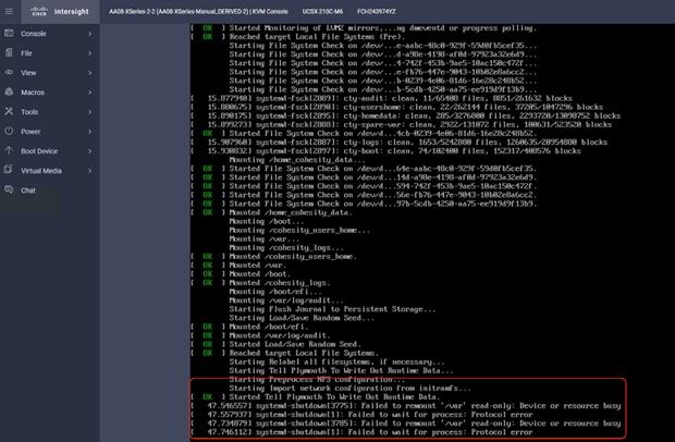
IPMI Warning on Cohesity System Health Status
When the Cohesity cluster is configured, you may see “IPMI config Absent” alerts on Cohesity Health Tab. Cisco X-Series with Cohesity does not require any IPMI configuration on the cluster. Please ignore this warning or contact Cohesity support for more details.
The warning is detailed below:
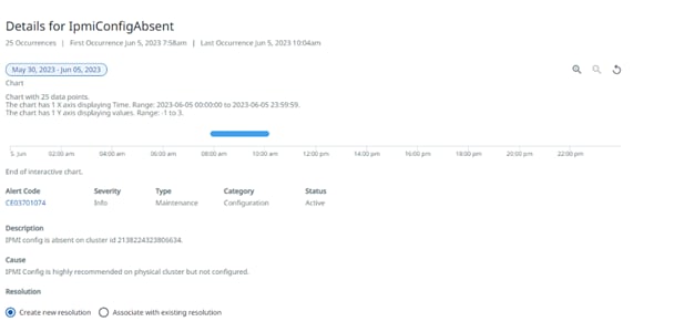
Appendix D – Recommended for You
Cisco Intersight Help Center: https://intersight.com/help/saas/home
Product Installation Guide: https://www.cisco.com/c/en/us/support/servers-unified-computing/ucs-x-series-modular-system/products-installation-guides-list.html
https://www.cisco.com/c/en/us/solutions/global-partners/cohesity.html
https://www.cohesity.com/solutions/technology-partners/cisco/
Cohesity Cloud Edition Setup Guide for AWS
Install Guide: https://docs.cohesity.com/Setup/PDFs/SetupGuideCloudEditionAWS.pdf.
Install Guide: https://docs.cohesity.com/hardware/PDFs/SetupGuideCiscoXseries.pdf
Ansible automation for Cohesity server profile for Cisco UCS X-Series: https://developer.cisco.com/codeexchange/github/repo/ucs-compute-solutions/intersight_cohesity_xseries_ansible/
This glossary addresses some terms used in this document, for the purposes of aiding understanding. This is not a complete list of all multicloud terminology. Some Cisco product links are supplied here also, where considered useful for the purposes of clarity, but this is by no means intended to be a complete list of all applicable Cisco products.
| aaS/XaaS (IT capability provided as a Service) |
Some IT capability, X, provided as a service (XaaS). Some benefits are:
● The provider manages the design, implementation, deployment, upgrades, resiliency, scalability, and overall delivery of the service and the infrastructure that supports it.
● There are very low barriers to entry, so that services can be quickly adopted and dropped in response to business demand, without the penalty of inefficiently utilized CapEx.
● The service charge is an IT OpEx cost (pay-as-you-go), whereas the CapEx and the service infrastructure is the responsibility of the provider.
● Costs are commensurate to usage and hence more easily controlled with respect to business demand and outcomes.
Such services are typically implemented as “microservices,” which are accessed via REST APIs. This architectural style supports composition of service components into systems. Access to and management of aaS assets is via a web GUI and/or APIs, such that Infrastructure-as-code (IaC) techniques can be used for automation, for example, Ansible and Terraform. The provider can be any entity capable of implementing an aaS “cloud-native” architecture. The cloud-native architecture concept is well-documented and supported by open-source software and a rich ecosystem of services such as training and consultancy. The provider can be an internal IT department or any of many third-party companies using and supporting the same open-source platforms. Service access control, integrated with corporate IAM, can be mapped to specific users and business activities, enabling consistent policy controls across services, wherever they are delivered from. |
| Ansible |
An infrastructure automation tool, used to implement processes for instantiating and configuring IT service components, such as VMs on an IaaS platform. Supports the consistent execution of processes defined in YAML “playbooks” at scale, across multiple targets. Because the Ansible artefacts (playbooks) are text-based, they can be stored in a Source Code Management (SCM) system, such as GitHub. This allows for software development like processes to be applied to infrastructure automation, such as, Infrastructure-as-code (see IaC below). |
| PaaS (Platform-as-a-Service) |
PaaS is a layer of value-add services, typically for application development, deployment, monitoring, and general lifecycle management. The use of IaC with IaaS and PaaS is very closely associated with DevOps practices. |
| Private on-premises data center |
A data center infrastructure housed within an environment owned by a given enterprise is distinguished from other forms of data center, with the implication that the private data center is more secure, given that access is restricted to those authorized by the enterprise. Thus, circumstances can arise where very sensitive IT assets are only deployed in a private data center, in contrast to using public IaaS. For many intents and purposes, the underlying technology can be identical, allowing for hybrid deployments where some IT assets are privately deployed but also accessible to other assets in public IaaS. IAM, VPNs, firewalls, and similar are key technologies needed to underpin the security of such an arrangement. |
| REST API |
Representational State Transfer (REST) APIs is a generic term for APIs accessed over HTTP(S), typically transporting data encoded in JSON or XML. REST APIs have the advantage that they support distributed systems, communicating over HTTP, which is a well-understood protocol from a security management perspective. REST APIs are another element of a cloud-native applications architecture, alongside microservices. https://en.wikipedia.org/wiki/Representational_state_transfer |
| SaaS (Software-as-a-Service) |
End-user applications provided “aaS” over the public Internet, with the underlying software systems and infrastructure owned and managed by the provider. |
AAA—Authentication, Authorization, and Accounting
ACP—Access-Control Policy
ACI—Cisco Application Centric Infrastructure
ACK—Acknowledge or Acknowledgement
ACL—Access-Control List
AD—Microsoft Active Directory
AFI—Address Family Identifier
AMP—Cisco Advanced Malware Protection
AP—Access Point
API—Application Programming Interface
APIC— Cisco Application Policy Infrastructure Controller (ACI)
ASA—Cisco Adaptative Security Appliance
ASM—Any-Source Multicast (PIM)
ASR—Aggregation Services Router
Auto-RP—Cisco Automatic Rendezvous Point protocol (multicast)
AVC—Application Visibility and Control
BFD—Bidirectional Forwarding Detection
BGP—Border Gateway Protocol
BMS—Building Management System
BSR—Bootstrap Router (multicast)
BYOD—Bring Your Own Device
CAPWAP—Control and Provisioning of Wireless Access Points Protocol
CDP—Cisco Discovery Protocol
CEF—Cisco Express Forwarding
CMD—Cisco Meta Data
CPU—Central Processing Unit
CSR—Cloud Services Routers
CTA—Cognitive Threat Analytics
CUWN—Cisco Unified Wireless Network
CVD—Cisco Validated Design
CYOD—Choose Your Own Device
DC—Data Center
DHCP—Dynamic Host Configuration Protocol
DM—Dense-Mode (multicast)
DMVPN—Dynamic Multipoint Virtual Private Network
DMZ—Demilitarized Zone (firewall/networking construct)
DNA—Cisco Digital Network Architecture
DNS—Domain Name System
DORA—Discover, Offer, Request, ACK (DHCP Process)
DWDM—Dense Wavelength Division Multiplexing
ECMP—Equal Cost Multi Path
EID—Endpoint Identifier
EIGRP—Enhanced Interior Gateway Routing Protocol
EMI—Electromagnetic Interference
ETR—Egress Tunnel Router (LISP)
EVPN—Ethernet Virtual Private Network (BGP EVPN with VXLAN data plane)
FHR—First-Hop Router (multicast)
FHRP—First-Hop Redundancy Protocol
FMC—Cisco Firepower Management Center
FTD—Cisco Firepower Threat Defense
GBAC—Group-Based Access Control
GbE—Gigabit Ethernet
Gbit/s—Gigabits Per Second (interface/port speed reference)
GRE—Generic Routing Encapsulation
GRT—Global Routing Table
HA—High-Availability
HQ—Headquarters
HSRP—Cisco Hot-Standby Routing Protocol
HTDB—Host-tracking Database (SD-Access control plane node construct)
IBNS—Identity-Based Networking Services (IBNS 2.0 is the current version)
ICMP— Internet Control Message Protocol
IDF—Intermediate Distribution Frame; essentially a wiring closet.
IEEE—Institute of Electrical and Electronics Engineers
IETF—Internet Engineering Task Force
IFM—Intelligent Fabric Module
IGP—Interior Gateway Protocol
IID—Instance-ID (LISP)
IOE—Internet of Everything
IoT—Internet of Things
IP—Internet Protocol
IPAM—IP Address Management
IPS—Intrusion Prevention System
IPSec—Internet Protocol Security
ISE—Cisco Identity Services Engine
ISR—Integrated Services Router
IS-IS—Intermediate System to Intermediate System routing protocol
ITR—Ingress Tunnel Router (LISP)
LACP—Link Aggregation Control Protocol
LAG—Link Aggregation Group
LAN—Local Area Network
L2 VNI—Layer 2 Virtual Network Identifier; as used in SD-Access Fabric, a VLAN.
L3 VNI— Layer 3 Virtual Network Identifier; as used in SD-Access Fabric, a VRF.
LHR—Last-Hop Router (multicast)
LISP—Location Identifier Separation Protocol
MAC—Media Access Control Address (OSI Layer 2 Address)
MAN—Metro Area Network
MEC—Multichassis EtherChannel, sometimes referenced as MCEC
MDF—Main Distribution Frame; essentially the central wiring point of the network.
MnT—Monitoring and Troubleshooting Node (Cisco ISE persona)
MOH—Music on Hold
MPLS—Multiprotocol Label Switching
MR—Map-resolver (LISP)
MS—Map-server (LISP)
MSDP—Multicast Source Discovery Protocol (multicast)
MTU—Maximum Transmission Unit
NAC—Network Access Control
NAD—Network Access Device
NAT—Network Address Translation
NBAR—Cisco Network-Based Application Recognition (NBAR2 is the current version).
NFV—Network Functions Virtualization
NSF—Non-Stop Forwarding
OSI—Open Systems Interconnection model
OSPF—Open Shortest Path First routing protocol
OT—Operational Technology
PAgP—Port Aggregation Protocol
PAN—Primary Administration Node (Cisco ISE persona)
PCI DSS—Payment Card Industry Data Security Standard
PD—Powered Devices (PoE)
PETR—Proxy-Egress Tunnel Router (LISP)
PIM—Protocol-Independent Multicast
PITR—Proxy-Ingress Tunnel Router (LISP)
PnP—Plug-n-Play
PoE—Power over Ethernet (Generic term, may also refer to IEEE 802.3af, 15.4W at PSE)
PoE+—Power over Ethernet Plus (IEEE 802.3at, 30W at PSE)
PSE—Power Sourcing Equipment (PoE)
PSN—Policy Service Node (Cisco ISE persona)
pxGrid—Platform Exchange Grid (Cisco ISE persona and publisher/subscriber service)
PxTR—Proxy-Tunnel Router (LISP – device operating as both a PETR and PITR)
QoS—Quality of Service
RADIUS—Remote Authentication Dial-In User Service
REST—Representational State Transfer
RFC—Request for Comments Document (IETF)
RIB—Routing Information Base
RLOC—Routing Locator (LISP)
RP—Rendezvous Point (multicast)
RP—Redundancy Port (WLC)
RP—Route Processer
RPF—Reverse Path Forwarding
RR—Route Reflector (BGP)
RTT—Round-Trip Time
SA—Source Active (multicast)
SAFI—Subsequent Address Family Identifiers (BGP)
SD—Software-Defined
SDA—Cisco Software Defined-Access
SDN—Software-Defined Networking
SFP—Small Form-Factor Pluggable (1 GbE transceiver)
SFP+— Small Form-Factor Pluggable (10 GbE transceiver)
SGACL—Security-Group ACL
SGT—Scalable Group Tag, sometimes reference as Security Group Tag
SM—Spare-mode (multicast)
SNMP—Simple Network Management Protocol
SSID—Service Set Identifier (wireless)
SSM—Source-Specific Multicast (PIM)
SSO—Stateful Switchover
STP—Spanning-tree protocol
SVI—Switched Virtual Interface
SVL—Cisco StackWise Virtual
SWIM—Software Image Management
SXP—Scalable Group Tag Exchange Protocol
Syslog—System Logging Protocol
TACACS+—Terminal Access Controller Access-Control System Plus
TCP—Transmission Control Protocol (OSI Layer 4)
UCS— Cisco Unified Computing System
UDP—User Datagram Protocol (OSI Layer 4)
UPoE—Cisco Universal Power Over Ethernet (60W at PSE)
UPoE+— Cisco Universal Power Over Ethernet Plus (90W at PSE)
URL—Uniform Resource Locator
VLAN—Virtual Local Area Network
VM—Virtual Machine
VN—Virtual Network, analogous to a VRF in SD-Access
VNI—Virtual Network Identifier (VXLAN)
vPC—virtual Port Channel (Cisco Nexus)
VPLS—Virtual Private LAN Service
VPN—Virtual Private Network
VPNv4—BGP address family that consists of a Route-Distinguisher (RD) prepended to an IPv4 prefix
VPWS—Virtual Private Wire Service
VRF—Virtual Routing and Forwarding
VSL—Virtual Switch Link (Cisco VSS component)
VSS—Cisco Virtual Switching System
VXLAN—Virtual Extensible LAN
WAN—Wide-Area Network
WLAN—Wireless Local Area Network (generally synonymous with IEEE 802.11-based networks)
WoL—Wake-on-LAN
xTR—Tunnel Router (LISP – device operating as both an ETR and ITR)
For comments and suggestions about this guide and related guides, join the discussion on Cisco Community at https://cs.co/en-cvds.
ALL DESIGNS, SPECIFICATIONS, STATEMENTS, INFORMATION, AND RECOMMENDATIONS (COLLECTIVELY, "DESIGNS") IN THIS MANUAL ARE PRESENTED "AS IS," WITH ALL FAULTS. CISCO AND ITS SUPPLIERS DISCLAIM ALL WARRANTIES, INCLUDING, WITHOUT LIMITATION, THE WARRANTY OF MERCHANTABILITY, FITNESS FOR A PARTICULAR PURPOSE AND NONINFRINGEMENT OR ARISING FROM A COURSE OF DEALING, USAGE, OR TRADE PRACTICE. IN NO EVENT SHALL CISCO OR ITS SUPPLIERS BE LIABLE FOR ANY INDIRECT, SPECIAL, CONSEQUENTIAL, OR INCIDENTAL DAMAGES, INCLUDING, WITHOUT LIMITATION, LOST PROFITS OR LOSS OR DAMAGE TO DATA ARISING OUT OF THE USE OR INABILITY TO USE THE DESIGNS, EVEN IF CISCO OR ITS SUPPLIERS HAVE BEEN ADVISED OF THE POSSIBILITY OF SUCH DAMAGES.
THE DESIGNS ARE SUBJECT TO CHANGE WITHOUT NOTICE. USERS ARE SOLELY RESPONSIBLE FOR THEIR APPLICATION OF THE DESIGNS. THE DESIGNS DO NOT CONSTITUTE THE TECHNICAL OR OTHER PROFESSIONAL ADVICE OF CISCO, ITS SUPPLIERS OR PARTNERS. USERS SHOULD CONSULT THEIR OWN TECHNICAL ADVISORS BEFORE IMPLE-MENTING THE DESIGNS. RESULTS MAY VARY DEPENDING ON FACTORS NOT TESTED BY CISCO.
CCDE, CCENT, Cisco Eos, Cisco Lumin, Cisco Nexus, Cisco StadiumVision, Cisco TelePresence, Cisco WebEx, the Cisco logo, DCE, and Welcome to the Human Network are trademarks; Changing the Way We Work, Live, Play, and Learn and Cisco Store are service marks; and Access Registrar, Aironet, AsyncOS, Bringing the Meeting To You, Catalyst, CCDA, CCDP, CCIE, CCIP, CCNA, CCNP, CCSP, CCVP, Cisco, the Cisco Certified Internetwork Expert logo, Cisco IOS, Cisco Press, Cisco Systems, Cisco Systems Capital, the Cisco Systems logo, Cisco Unified Computing System (Cisco UCS), Cisco UCS B-Series Blade Servers, Cisco UCS C-Series Rack Servers, Cisco UCS S-Series Storage Servers, Cisco UCS Manager, Cisco UCS Management Software, Cisco Unified Fabric, Cisco Application Centric Infrastructure, Cisco Nexus 9000 Series, Cisco Nexus 7000 Series. Cisco Prime Data Center Network Manager, Cisco NX-OS Software, Cisco MDS Series, Cisco Unity, Collaboration Without Limitation, EtherFast, EtherSwitch, Event Center, Fast Step, Follow Me Browsing, FormShare, GigaDrive, HomeLink, Internet Quotient, IOS, iPhone, iQuick Study, LightStream, Linksys, MediaTone, MeetingPlace, MeetingPlace Chime Sound, MGX, Networkers, Networking Academy, Network Registrar, PCNow, PIX, PowerPanels, ProConnect, ScriptShare, SenderBase, SMARTnet, Spectrum Expert, StackWise, The Fastest Way to Increase Your Internet Quotient, TransPath, WebEx, and the WebEx logo are registered trade-marks of Cisco Systems, Inc. and/or its affiliates in the United States and certain other countries. (LDW_U1_P4***)
All other trademarks mentioned in this document or website are the property of their respective owners. The use of the word partner does not imply a partnership relationship between Cisco and any other company. (0809R)