Hybrid Cloud – HyperFlex Backup, Disaster Recovery, and Archival with Cohesity Design and Deployment Guide
Available Languages
Bias-Free Language
The documentation set for this product strives to use bias-free language. For the purposes of this documentation set, bias-free is defined as language that does not imply discrimination based on age, disability, gender, racial identity, ethnic identity, sexual orientation, socioeconomic status, and intersectionality. Exceptions may be present in the documentation due to language that is hardcoded in the user interfaces of the product software, language used based on RFP documentation, or language that is used by a referenced third-party product. Learn more about how Cisco is using Inclusive Language.
- US/Canada 800-553-2447
- Worldwide Support Phone Numbers
- All Tools
 Feedback
 Feedback
In partnership with:

About the Cisco Validated Design Program
The Cisco Validated Design (CVD) program consists of systems and solutions designed, tested, and documented to facilitate faster, more reliable, and more predictable customer deployments. For more information, go to: http://www.cisco.com/go/designzone.
The frequency of high-cost disasters stemming from cyber attacks and weather and climate disasters is rising, making disaster recovery (DR) a top priority for every business today. DR is the ability to recover systems and resume business operations quickly after a disaster. Backing up enterprise data including workloads and file services to a secondary location, archival of older, infrequently accessed data that remains important to the organization, and replication between primary and second-ary sites — whether on-premise to cloud, cloud to on-premise, or cloud-to-cloud — are all critical components of a DR strategy.
To help enable the organization to resume operations after a disaster, a DR strategy requires both mission-critical and non-mission-critical workloads running across the primary, edge, and remote sites to be replicated fully on the secondary, off-premises site. It may also require the transfer of data in the primary environment on a regular basis to the DR site to ensure the organization has a recent copy of all its enterprise data, including databases, file services, applications, and virtual machines.
As hybrid cloud architecture becomes the norm, IT teams need to eliminate data silos to support backup, file sharing, disaster recovery, development/test provisioning, and analytics to help move the organization further and faster towards digital business success. Customers are looking for ways to utilize the public cloud environment as a secondary site if it can be easily used and managed for disaster recovery.
Cohesity Data Cloud deployed in the public cloud is designed to provide data protection and management by supporting cloud DR, development/test, and cloud-native backup. This solution enables customers to transform a private cloud into a hybrid cloud (on-premises and public cloud) infrastructure and facilitates replication between sites — whether on-premise to cloud, cloud to on-premise, or cloud-to-cloud.
The Cisco UCS® X-Series with Cisco Intersight™ is built for the hybrid cloud environment. It is designed to meet the needs of modern applications and improve operational efficiency, agility, and scale through an adaptable, future-ready, modular design. This is a modular system managed from the cloud using Cisco Intersight.
The present solution provides customers with a choice for recovering their virtual infrastructure services running either on hyper-converged or converged systems and deployed across a hybrid cloud environment.
● Recovery from archives existing on public clouds like AWS. The solution presents a reference architecture, design details and validation for recovery from archives utilizing Cohesity Data Cloud. During a disaster or failure of primary or edge site, customers can recover from archives to a public cloud such as AWS. Moreover, the solution elaborates on a workflow to failback either to a new location or the existing location. Best suited for non-mission critical workloads, this design benefits from the cost-effectiveness of a public cloud service but yields high Recovery Time Objectives (RTOs).
● Recovery from replicated backups on public clouds like AWS. A reference architecture, design details and validation are elaborated in this document for recovery from backups replicated on Cohesity Data Cloud instances running on a public cloud such as AWS. During failure of primary or edge sites, Customers can failover or switch production to a backup facility such virtual instances running in AWS and thereafter can failback or return production to either the original or a new location. This design, best suited for mission critical workloads, incurs high public cloud service costs but will have low RTOs.
This chapter contains the following:
● Overview
● Audience
Design and Deployment of a secure hybrid disaster recovery solution is challenging for organizations due to the requirements to correctly choose and manage the best performing, secure and reliant data protection and infrastructure services spread across several locations across private and public cloud environments. The amount of resources needed, costs of setting up, testing, and maintaining a secondary data center are very high almost the same cost as the entire production environment, especially considering organizations rarely use it. It is challenging to keep a minimal data footprint with adequate protection, continuously synchronize the data and establish seamless failover and failback. After building out a disaster recovery site, the challenge then becomes to replicate data from the production environment, and to keep it in synchronized going forward.
The Hybrid Cloud solution with Cisco Intersight, Cisco X-Series modular system and Cohesity Data Cloud enables customers to protect and secure their primary, remote, edge or public cloud virtual infrastructure environment with a combination of on-premises and public cloud Data Protection services. This solution provides customers with a choice of disaster recovery services depending on the application recovery SLAs and cost to protect their multi-site deployments
Audience
The intended audience for this document includes, but is not limited to, sales engineers, field consultants, professional ser-vices, IT managers, IT engineers, partners, and customers who are interested in learning about and deploying a secure Disaster recovery solution across a hybrid cloud environment for mission critical and non-mission critical workloads.
This document describes the design, configuration, and validated use cases for the Cisco Hybrid Cloud solution for Disaster recovery with Cohesity Data Cloud on Cisco X-Series modular platform, of Virtual Infrastructure deployed on Cisco HyperFlex.
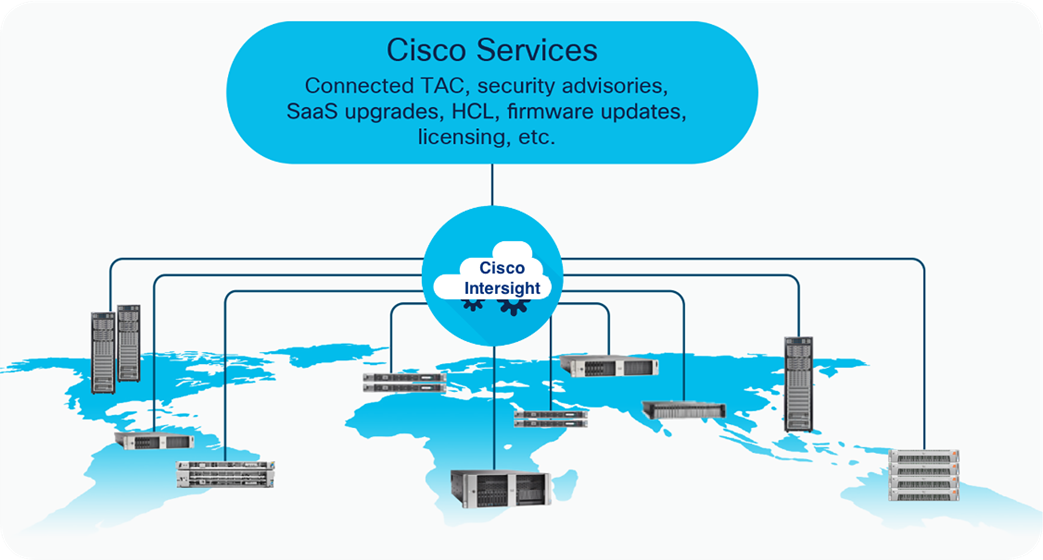
Cisco Intersight is a cloud operations platform that delivers intelligent visualization, optimization, and orchestration for applications and infrastructure across public cloud and on-premises environments. Cisco Intersight provides an essential control point for customers to get more value from hybrid IT investments by simplifying operations across on-prem and their public clouds, continuously optimizing their multi cloud environments and accelerating service delivery to address business needs.
The Cisco UCS® X-Series with Cisco Intersight™ is a modular system managed from the cloud. It is designed to be shaped to meet the needs of modern applications and improve operational efficiency, agility, and scale through an adaptable, future-ready, modular design. The Cisco UCS X-Series Modular System (UCS X-Series) provides functionalities of both blade and rack servers by offering compute density, storage capacity, and expandability in a single system.
The Cohesity Data Cloud is a unified platform for securing, managing, and extracting value from enterprise data. This software-defined platform spans across core, cloud, and edge, can be managed from a single GUI, and enables independent apps to run in the same environment. It is the only solution built on a hyperconverged, scale-out design that converges backup, files and objects, dev/test, and analytics, and uniquely allows applications to run on the same platform to extract insights from data. Designed with Google-like principles, it delivers true global deduplication and impressive storage efficiency that spans edge to core to the public cloud.
Cohesity Data Cloud deployed in the public cloud ensures cloud data protection and management by supporting cloud DR, dev/test, and cloud-native backup. With Cohesity’s Date Cloud, enterprises can transform a private cloud into a hybrid cloud (on-premises and public cloud) infrastructure. Enterprises can then leverage Cohesity’s hybrid data fabric in order to manage secondary storage and data sprawl efficiently and securely.
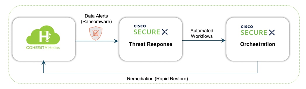
Cohesity Data Cloud integrates with Cisco SecureX, providing a unified platform for a simplified security experience. This integration adds visibility and context to data “events of interest,” complementing Cisco’s existing capabilities to automatically aggregate signals from networks, endpoints, clouds, and apps. IT administrators and Security Operations Centers (SOCs) can concurrently view alerts when a ransomware attack against enterprise data is detected. Cisco SecureX collects and brings this information together with other threat intelligence sources, enabling SOCs to quickly investigate and initiate a snapshot recovery from within SecureX, if needed, for closed-loop remediation..
Figure 1 illustrates an overview of a Secure Data Protection and Disaster Recovery solution deployed in an Hybrid Cloud environment utilizing best in class infrastructure , security, and data protection services from Cisco and Cohesity.
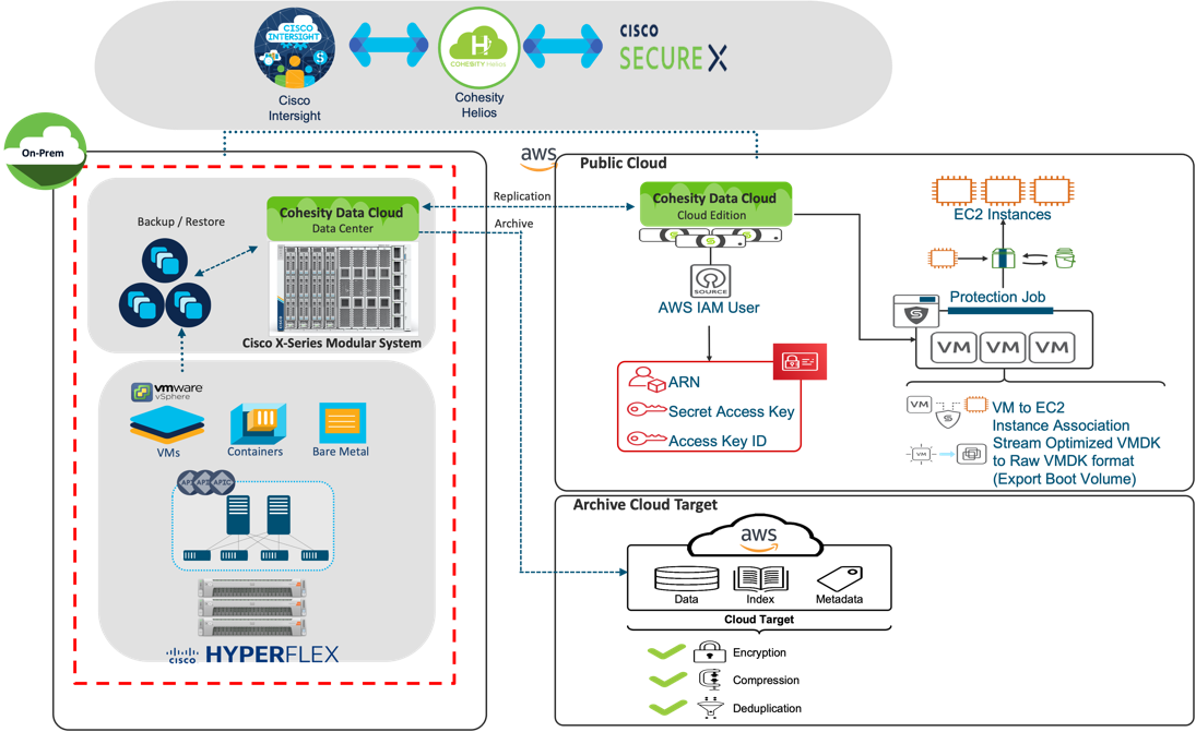
The key elements of this solution are:
● Cisco Intersight, software-as-a-service (SaaS) infrastructure lifecycle management platform that delivers simplified configuration, deployment, maintenance, and support services Ease of management of hybrid cloud environment. Cisco Intersight infrastructure services include the deployment, monitoring, management, and support of your physical and virtual infrastructure. Cisco Intersight provides a single management platform for Cisco X-Series modular systems, Cisco UCS and Cisco HyperFlex hyperconverged infrastructure (HCI) deployed across primary, edge or remote locations.
● Cisco X-Series modular system, equipped with at least 4x of ALL NVMe X210c nodes with 2x 3rd Gen Intel® Xeon® Scalable Processors and 92.8 TB of storage per node, provides both compute and storage with exceptional backup and recovery performance.
● Cohesity Data Cloud deployed in platform providing secure Data Protection and Disaster Recovery services across a hybrid cloud environment.
● An integrated data protection and security solution with Cisco SecureX, based on Cohesity DataProtect which automates the delivery of critical security information to organizations facing ransomware threats, helping to accelerate time to discovery, investigation, and remediation.
● Cisco HyperFlex™ systems with Intel® Xeon® Scalable processors delivering hyperconvergence with power and simplicity for any application, anywhere with management through the Cisco Intersight™ cloud operations platform.
This chapter contains the following:
● Cisco HyperFlex HX Data Platform Software
● Cisco HyperFlex HX Data Platform Controller
● All-NVMe and All-Flash Versus Hybrid Nodes
● Cisco HyperFlex Connect HTML 5 Management Webpage
● Cisco Unified Computing System X-Series
● Cisco SecureX and Cohesity Data Cloud Integration
The SaaS Cisco Intersight infrastructure lifecycle management platform delivers simplified configuration, deployment, maintenance, and support. It is designed to be modular, so you can adopt services based on your individual requirements. The platform significantly simplifies IT operations by bridging applications with infrastructure, providing visibility and management from bare-metal servers and hypervisors to serverless applications, thereby reducing costs and mitigating risk. This unified SaaS platform uses a unified open application programming interface (API) design that natively integrates with the third-party platforms and tools.
The main benefits of Cisco Intersight infrastructure services are:
● Simplify daily operations by automating many daily manual tasks.
● Combine the convenience of a SaaS platform with the capability to connect from anywhere and manage infrastructure through a browser or mobile app.
● Stay ahead of problems and accelerate trouble resolution through advanced support capabilities.
● Gain global visibility of infrastructure health and status along with advanced management and support capabilities.
● Upgrade to add workload optimization and Kubernetes services when needed.
Cisco Intersight Virtual Appliance and Private Virtual Appliance
In addition to the SaaS deployment model running on Intersight.com, you can purchase on-premises options separately. The Cisco Intersight virtual appliance and Cisco Intersight private virtual appliance are available for organizations that have additional data locality or security requirements for managing systems. The Cisco Intersight virtual appliance delivers the management features of the Cisco Intersight platform in an easy-to-deploy VMware Open Virtualization Appliance (OVA) or Microsoft Hyper-V Server virtual machine that allows you to control the system details that leave your premises. The Cisco Intersight private virtual appliance is provided in a form factor designed specifically for users who operate in disconnected (air gap) environments. The private virtual appliance requires no connection to public networks or to Cisco network.
Cisco Intersight Assist
Cisco Intersight Assist helps you add endpoint devices to the Cisco Intersight platform. A datacenter could have multiple devices that do not connect directly with the platform. Any device that the Cisco Intersight platform supports but does not connect with directly must have a connection mechanism, and Cisco Intersight Assist provides it. In FlashStack, VMware vCenter and Pure Storage FlashArray connect to the Intersight platform with the help of the Cisco Intersight Assist virtual machine.
Cisco Intersight Assist is available within the Cisco Intersight virtual appliance, which is distributed as a deployable virtual machine contained within an OVA file format. Later sections in this paper have more details about the Cisco Intersight Assist virtual-machine deployment configuration.
Cisco Intersight Cloud Orchestrator
Cisco Intersight Cloud Orchestrator is a powerful automation tool that enables IT operations teams not just to move at the speed of the business and standardize while reducing risk across all domains but also to provide a consistent cloud-like experience for users.
Cisco Intersight Cloud Orchestrator simplifies orchestration and automation for infrastructure and workloads across hybrid cloud by providing an easy-to-use workflow designer. Based on a library of curated, multi-domain tasks (custom or provided by Cisco), it enables users to create workflows, quickly and easily, without being coding experts! This enables quick and easy automation and deployment of any infrastructure resource, from servers, to VMs and the network, taking away some of the complexity of operating your hybrid IT environment.
The ICO workflow designer provides:
● Low/no-code workflow creation with a modern, drag-and-drop user experience with control flow support. The workflow designer includes policy-based, built-in tasks for Cisco UCS, virtualization, and other Cisco devices. A Software Development Kit (SDK) enables Cisco technology partners to build their own ICO tasks to develop custom solutions.
● Rollback capabilities to selectively undo a workflow’s tasks in the event of failure, or to deprovision infrastructure, which when done manually can often take longer and be more error prone than straight provisioning.
● Extensibility with a task designer that expands the functionality of currently supported targets or can be used to create new ones. ICO currently supports Web API with more integration options to come.
With Cisco Intersight Cloud Orchestrator you can truly evolve your automation strategy to provide consistent experience across on-premises resources and public clouds.
Key benefits:
● Bring your public cloud and on-premises resources together with a solution that extends orchestration across any infrastructure and workload and integrates with the tools of your choice.
● Save time and streamline automation with a user-friendly GUI-based designer that makes it easy to create and execute com-plex workflows without being a coding expert.
● Standardize your deployment process with self-service delivery and boost productivity with a selection of validated blue-prints.
● Reduce risks by enforcing policy using rules for what can be orchestrated and who can access workflows and tasks.
Licensing Requirements
The Cisco Intersight platform uses a subscription-based license with multiple tiers. You can purchase a subscription duration of 1, 3, or 5 years and choose the required Cisco UCS server volume tier for the selected subscription duration. Each Cisco endpoint automatically includes a Cisco Intersight Base license at no additional cost when you access the Cisco Intersight portal and claim a device. You can purchase any of the following higher-tier Cisco Intersight licenses using the Cisco ordering tool:
● Cisco Intersight Essentials: Essentials includes all the functions of the Base license plus additional features, including Cisco UCS Central software and Cisco Integrated Management Controller (IMC) supervisor entitlement, policy-based configuration with server profiles, firmware management, and evaluation of compatibility with the Cisco Hardware Compatibility List (HCL).
● Cisco Intersight Advantage: Advantage offers all the features and functions of the Base and Essentials tiers. It also includes storage widgets and cross-domain inventory correlation across compute, storage, and virtual environments (VMware ESXi). OS installation for supported Cisco UCS platforms is also included.
● Cisco Intersight Premier: In addition to the functions provided in the Advantage tier, Premier includes full subscription entitlement for Cisco UCS Director, providing orchestration across Cisco UCS and third-party systems.
Servers in the Cisco Intersight managed mode require at least the Essentials license. For more information about the features provided in the various licensing tiers, see: https://intersight.com/help/getting_started#licensing_requirements.
Cisco HyperFlex HX Data Platform Software
The Cisco HyperFlex HX Data Platform is a purpose-built, high-performance, distributed file system with a wide array of enterprise-class data management services. The data platform’s innovations redefine distributed storage technology, exceeding the boundaries of first-generation hyperconverged infrastructures. The data platform has all the features expected in an enterprise shared storage system, eliminating the need to configure and maintain complex Fibre Channel storage networks and devices. The platform simplifies operations and helps ensure data availability. Enterprise-class storage features include the following:
● Data protection creates multiple copies of the data across the cluster so that data availability is not affected if single or multiple components fail (depending on the replication factor configured).
● Deduplication is always on, helping reduce storage requirements in virtualization clusters in which multiple operating system instances in guest virtual machines result in large amounts of replicated data.
● Compression further reduces storage requirements, reducing costs, and the log-structured file system is designed to store variable-sized blocks, reducing internal fragmentation.
● Replication copies virtual machine–level snapshots from one Cisco HyperFlex cluster to another to facilitate recovery from a cluster or site failure through failover to the secondary site of all the virtual machines.
● Thin provisioning allows large volumes to be created without requiring storage to support them until the need arises, simplifying data volume growth and making storage a "pay as you grow" proposition.
● Fast, space-efficient clones rapidly duplicate virtual storage volumes so that virtual machines can be cloned simply through metadata operations, with actual data copied only for write operations.
● Snapshots help facilitate backup and remote-replication operations, which are needed in enterprises that require always-on data availability.
● Small Computer System Interface over IP (iSCSI) connectivity allows external systems to consume HX Data Platform storage by presenting volumes to be mounted by the external systems using the iSCSI protocol.
Cisco HyperFlex HX Data Platform Controller
A Cisco HyperFlex HX Data Platform controller resides on each node and implements the distributed file system. The controller runs as software in user space within a virtual machine and intercepts and handles all I/O from the guest virtual ma-chines. The storage controller virtual machine (SCVM) uses the VMDirectPath I/O feature to provide direct PCI passthrough control of the physical server’s SAS disk controller or direct control of the PCI-attached NVMe-based solid-state disks (SSDs). This method gives the controller virtual machine full control of the physical disk resources, using the SSD drives as a read-write caching layer and using the hard-disk drives (HDDs) or SSDs as a capacity layer for distributed storage.
The controller integrates the data platform into the VMware vSphere cluster through the use of three preinstalled VMware ESXi vSphere Installation Bundles (VIBs) on each node:
● scvmclient: This VIB, also called the Cisco HyperFlex IO Visor, provides a network file system (NFS) mount point so that the ESXi hypervisor can access the virtual disks that are attached to individual virtual machines. From the hypervisor’s perspective, it is simply attached to a network file system. The IO Visor intercepts guest virtual machine I/O traffic and intelligently redirects it to the Cisco HyperFlex SCVMs.
● STFSNasPlugin: The VMware API for Array Integration (VAAI) storage offload API allows vSphere to request advanced file system operations such as snapshots and cloning. The controller implements these operations through manipulation of the file system metadata rather than actual data copying, providing rapid response, and thus rapid deployment of new environments.
● stHypervisorSvc: This VIB adds enhancements and features needed for Cisco HyperFlex data protection and virtual machine replication.
All-NVMe and All-Flash Versus Hybrid Nodes
Cisco HyperFlex systems can be divided logically into two families: a collection of hybrid nodes, and a collection of all-flash or all-NVMe nodes.
Hybrid nodes use a combination of SSDs for the short-term storage caching layer and HDDs for the long-term storage capacity layer. The hybrid Cisco HyperFlex system is an excellent choice for entry-level or midrange storage solutions, and hybrid solutions have been successfully deployed in many nonperformance-sensitive virtual environments.
However, the number highly performance-sensitive and mission-critical applications being deployed is increasing rapidly. The primary challenge to hybrid Cisco HyperFlex systems for these performance-sensitive applications is their increased sensitivity to storage latency. Due to the characteristics of the spinning hard disks, which results in higher latency, HDDs almost inevitably become a bottleneck in a hybrid system. Ideally, if all the storage operations occurred on the caching SSD layer, the hybrid system’s performance would be excellent. But in some scenarios, the amount of data being written and read exceeds the caching layer capacity, placing larger loads on the HDD capacity layer, and the subsequent increase in latency results in reduced performance.
Cisco HyperFlex all-flash and all-NVMe systems are an excellent option for customers with high-performance, latency-sensitive workloads. Because the capacity layer disks are also SSDs, the all-flash and all-NVMe systems avoid the increased latency seen in hybrid nodes when large amounts of data are written and read. With a purpose-built, flash-optimized, high-performance log-based file system, the Cisco HyperFlex all-flash and all-NVMe systems provide these features:
● Predictable high performance across all the virtual machines the cluster
● Highly consistent and low latency, which benefits data-intensive applications
● Architecture that can continue to meet your needs in the future; it is well suited for flash-memory configuration, reducing write amplification and flash cell wear
● Cloud-scale solution with easy scale-out and distributed infrastructure and the flexibility to scale out independent resources separately
Cisco HyperFlex support for hybrid, all-flash, and all-NVMe models allows customers to choose the right platform configura-tion based on their capacity, applications, performance, and budget requirements. All-flash configurations offer repeatable and sustainable high performance, especially for scenarios with a larger working set of data—that is, a large amount of data in motion. All-NVMe configurations elevate performance to an even higher level, with lower latencies for the most demand-ing applications. Hybrid configurations are a good option for customers who want the simplicity of the Cisco HyperFlex solution, but whose needs are focused on capacity-sensitive solutions, lower budgets, and few performance-sensitive applications.
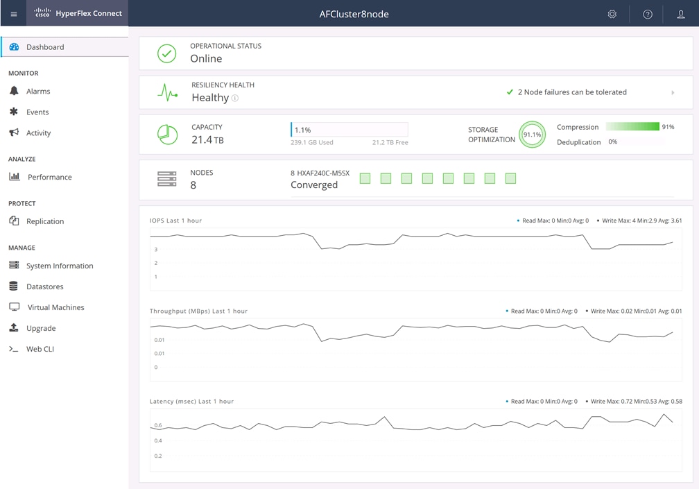
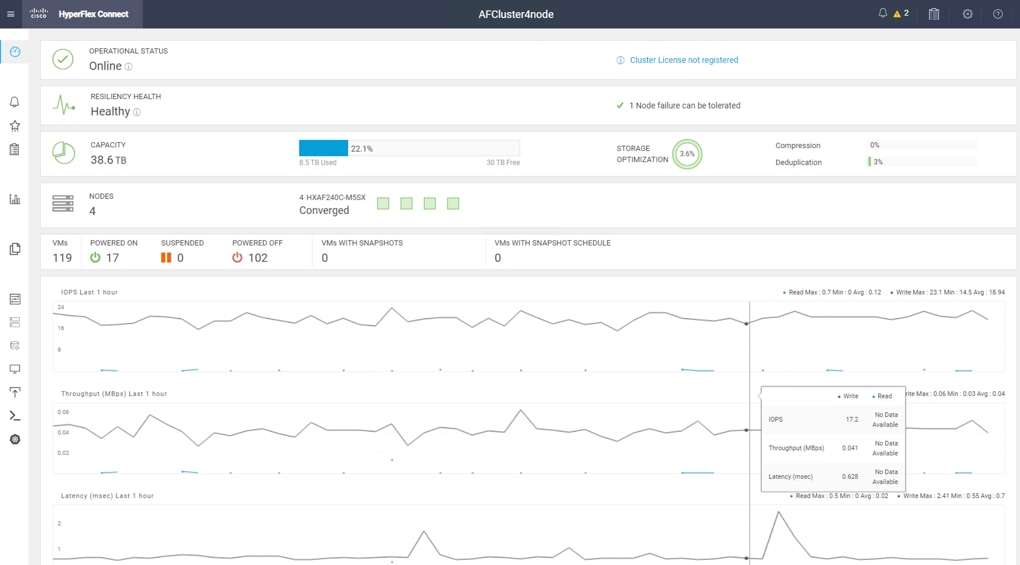
Cisco HyperFlex Connect HTML 5 Management Webpage
An HTML 5–based web user interface named Cisco HyperFlex Connect is available for use as the primary management tool for Cisco HyperFlex systems (Figure 3). Through this centralized point of control for the cluster, administrators can create data stores, monitor the data platform health and performance, manage resource use, and perform upgrades. Administrators can also use this management portal to predict when the cluster will need to be scaled, create virtual machine snapshot schedules, and configure native virtual machine replication. To use the Cisco HyperFlex Connect user interface, connect using a web browser to the Cisco HyperFlex cluster IP address: http://<hx controller cluster ip>.
Cisco Unified Computing System X-Series
The Cisco UCS X-Series modular system is designed to take the current generation of the Cisco UCS platform to the next level with its design that will support future innovations and management in the cloud (Figure 4). Decoupling and moving platform management to the cloud allows the Cisco UCS platform to respond to your feature and scalability requirements much faster and more efficiently. Cisco UCS X-Series state-of-the-art hardware simplifies the datacenter design by providing flexible server options. A single server type that supports a broader range of workloads results in fewer different datacenter products to manage and maintain. The Cisco Intersight cloud management platform manages the Cisco UCS X-Series as well as integrating with third-party devices. These devices include VMware vCenter and Pure Storage to provide visibility, optimization, and orchestration from a single platform, thereby enhancing agility and deployment consistency.
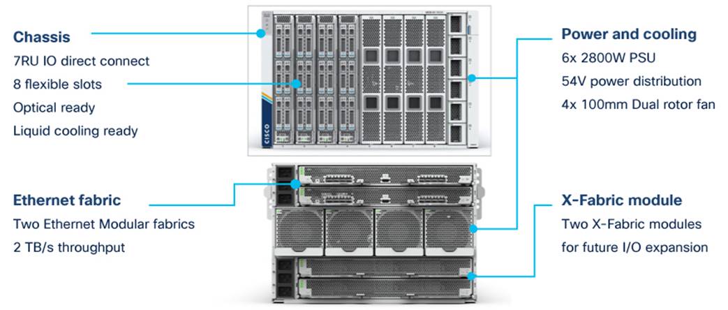
The Cisco UCS X-Series chassis is engineered to be adaptable and flexible. As shown in Figure 5, the only midplane of the UCSX-9508 chassis is just a power-distribution midplane. This innovative design provides fewer obstructions for better airflow. For I/O connectivity, vertically oriented compute nodes intersect with horizontally oriented fabric modules, allowing the chassis to support future fabric innovations. Superior packaging of the Cisco UCSX-9508 chassis enables larger compute nodes, thereby providing more space for actual compute components such as memory, GPU, drives, and accelerators. Improved airflow through the chassis enables support for higher-power components, and more space allows for future thermal solutions (such as liquid cooling) without limitations.
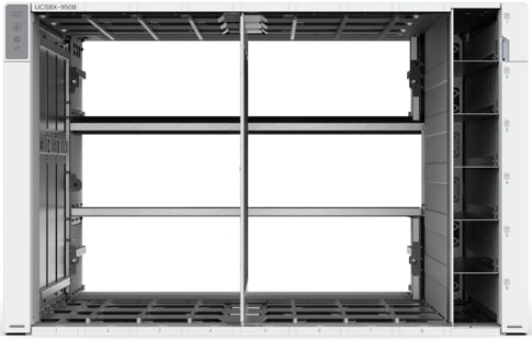
The Cisco UCSX-9508 7-rack-unit (7RU) chassis has 8 flexible slots. These slots can house a combination of compute nodes and a pool of future I/O resources that may include GPU accelerators, disk storage, and nonvolatile memory (NVM). At the top rear of the chassis are two intelligent fabric modules (IFM) that connect the chassis to upstream Cisco UCS 6400 Series fabric interconnects. At the bottom rear of the chassis are slots ready to house future X-Fabric modules that can flexibly connect the compute nodes with I/O devices. Six 2800W power supply units (PSUs) provide 54V DC power to the chassis with N, N+1, and N+N redundancy. A higher voltage allows efficient power delivery with less copper and reduced power loss. Efficient, 100-mm, dual counter-rotating fans deliver industry-leading airflow and power efficiency, and optimized thermal algorithms enable different cooling modes to best support your environment.
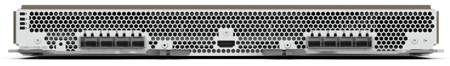
Cisco UCSX 9108-25G Intelligent Fabric Modules
For the Cisco UCSX-9508 chassis, a pair of Cisco UCS 9108-25G IFMs provide network connectivity. Like the fabric extenders used in the Cisco UCS 5108 Blade Server chassis, these modules carry all network traffic to a pair of Cisco UCS 6400 Series fabric interconnects. IFM also hosts a chassis management controller (CMC). High-speed PCIe-based fabric topology provides extreme flexibility compared to a combination of serial-attached SCSI (SAS), Serial Advanced Technology Attachment (SATA), or Fibre Channel. In contrast to systems with fixed networking components, the design of the Cisco UCSX-9508 enables easy upgrades to new networking technologies as they emerge, making it straightforward to accommodate new network speeds or technologies in the future.
Each IFM supports eight 25-Gb uplink ports for connecting the Cisco UCSX-9508 chassis to the fabric interconnects and thirty-two 25-Gb server ports for the 8 compute nodes. The IFM server ports can provide up to 200 Gbps of unified fabric connectivity per compute node across the two IFMs. The uplink ports connect the chassis to a Cisco UCS fabric interconnect to provide up to 400-Gbps connectivity across the two IFMs. The unified fabric carries management, virtual-machine, and Fibre Channel over Ethernet (FCoE) traffic to the fabric interconnects, where management traffic is routed to the Cisco Intersight cloud operations platform. FCoE traffic is forwarded to the native Fibre Channel interfaces through unified ports on the fabric interconnect (to Cisco MDS switches), and virtual-machine Ethernet traffic is forwarded upstream to the data center network (by Cisco Nexus switches).
Cisco UCS X210c M6 Server
The Cisco UCS X9508 chassis is designed to host up to 8 Cisco UCS X210c M6 servers. Figure 7 shows the hardware details of the Cisco UCS X210c M6 compute node.
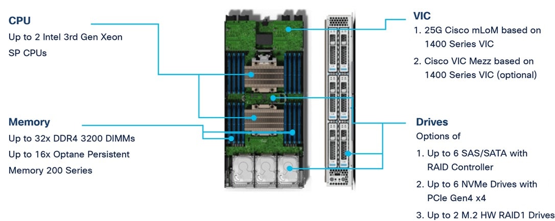
The following are the features of the Cisco UCS X210c M6:
● CPU: The X210c nodes supports, up to two 3rd generation Intel Xeon scalable processors with up to 40 cores per processor and a 1.5-MB Level 3 cache per core.
● Memory: Supports up to thirty-two 256-GB DDR4-3200 (DIMMs) for a maximum of 8 TB of main memory. You can configure the compute node for up to sixteen 512-GB Intel Optane persistent memory DIMMs for a maximum of 12 TB of memory.
● Disk storage: You can configure up to 6 SAS or SATA drives with an internal (RAID) controller or up to 6 nonvolatile memory express (NVMe) drives. You can add 2 M.2 memory cards to the compute node with RAID 1 mirroring.
● Virtual interface card: You can install up to 2 virtual interface cards, including a Cisco UCS Virtual Interface Card (VIC) modular LOM card (mLOM) 14425, and a mezzanine Cisco VIC 14825 in a compute node.
● Security: The server supports an optional trusted platform module (TPM). Additional security features include a secure a boot field-programmable gate array (FPGA) and ACT2 anti-counterfeit provisions.
Cisco UCS VICs
Cisco UCS X210c M6 compute nodes support the following two Cisco fourth-generation VIC cards:
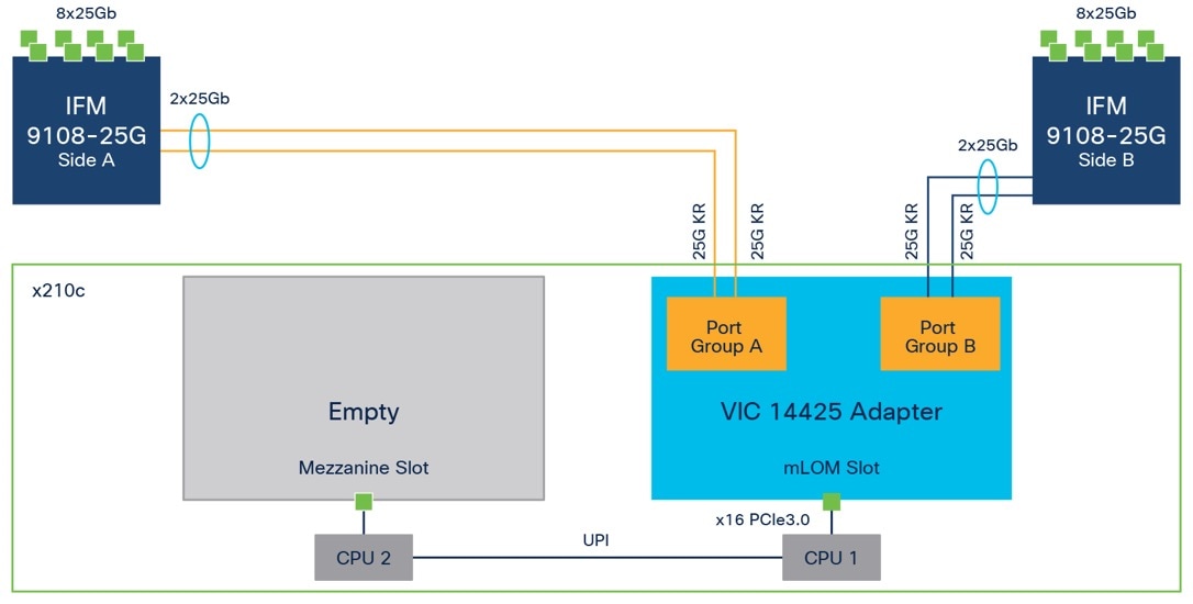
Cisco VIC 14425
Cisco VIC 14425 fits the mLOM slot in the Cisco X210c compute node and enables up to 50 Gbps of unified fabric connectivity to each of the chassis IFMs for a total of 100 Gbps of connectivity per server (Figure 8). Cisco VIC 14425 connectivity to the IFM and up to the fabric interconnects is delivered through four 25-Gbps connections that are configured automatically as two 50-Gbps port channels. Cisco VIC 14425 supports 256 virtual interfaces (both Fibre Channel and Ethernet) along with the latest networking innovations such as NVMe over Fabric over Remote Direct Memory Access (RDMA), RDMA over Converged Infrastructure (RoCEv2), Virtual Extensible VLAN gateway/Network Virtualization using Generic Routing Encapsulation (VxLAN/NVGRE) offload, and so on.
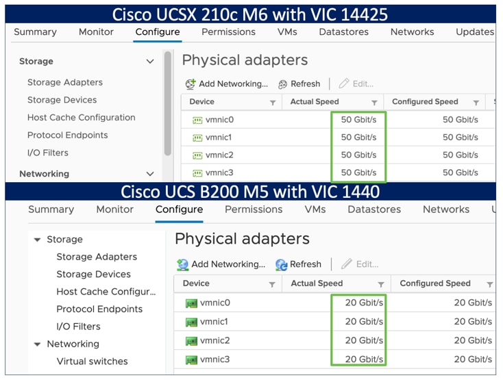
The connections between the fourth-generation Cisco VIC (Cisco UCS VIC 1440) in the Cisco UCS B200 blades and the I/O modules in the Cisco UCS VIC 5108 chassis comprise multiple 10-Gbps KR lanes. The same connections between Cisco VIC 14425 and IFM in the Cisco UCS X-Series comprise multiple 25-Gbps KR lanes, resulting in 2.5 times better connectivity in Cisco UCS X210c M6 compute nodes. The following screenshot shows the network interface speed comparison for VMware ESXi installed on the Cisco UCS B200 M5 with a VIC 1440 and Cisco UCSX 210c M6 with a VIC 14425.
Cisco VIC 14825
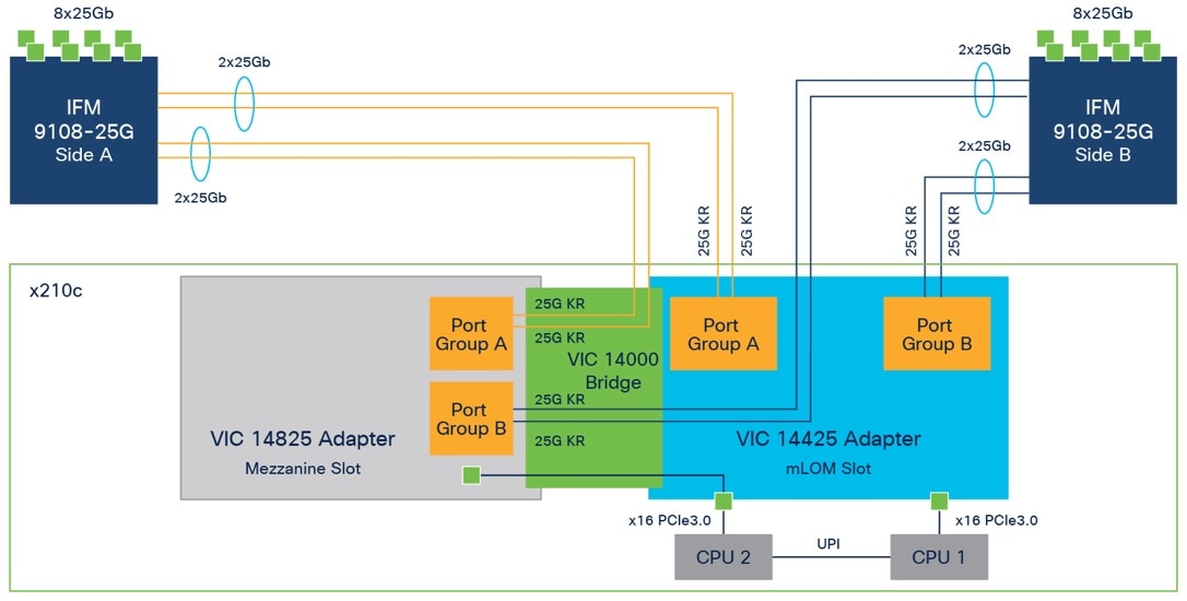
The optional Cisco VIC 14825 fits the mezzanine slot on the server. A bridge card (part number UCSX-V4-BRIDGE) extends the two 50 Gbps of network connections of this VIC up to the mLOM slot and out through the IFM connectors of the mLOM, bringing the total bandwidth to 100 Gbps per fabric for a total bandwidth of 200 Gbps per server (Figure 9).
Cisco UCS 6400 Fabric Interconnects
The Cisco UCS fabric interconnects provide a single point for connectivity and management for the entire Cisco UCS system. Typically deployed as an active-active pair, the fabric interconnects of the system integrate all components into a single, highly available management domain that Cisco UCS Manager or the Cisco Intersight platform manages. Cisco UCS fabric interconnects provide a single unified fabric for the system, with low-latency, lossless, cut-through switching that supports LAN, storage-area network (SAN), and management traffic using a single set of cables (Figure 10).

The Cisco UCS 6454 used in the current design is a 54-port fabric interconnect. This 1RU device includes twenty-eight 10-/25-GE ports, four 1-/10-/25-GE ports, six 40-/100-GE uplink ports, and sixteen unified ports that can support 10-/25-GE or 8-/16-/32-Gbps Fibre Channel, depending on the Small Form-Factor Pluggable (SFP) adapter.
Note: For supporting the Cisco UCS X-Series, you must configure the fabric interconnects in Cisco Intersight managed mode. This option replaces the local management with Cisco Intersight cloud (or appliance)-based management.
Cisco SecureX and Cohesity Data Cloud Integration
Cohesity + Cisco SecureX is the first-of-its-kind integrated data protection solution with Cisco SecureX. This integration automates the delivery of critical security information to organizations facing ransomware threats, helping to accelerate time to discovery, investigation, and remediation. It leverages Cohesity Data Cloud’s anomaly detection capability and automates the delivery of alerts into SecureX that indicate data and workloads may have been compromised. Security teams can then leverage SecureX facilities to expedite investigation within SecureX, and if needed, initiate a snapshot recovery from within SecureX for closed-loop remediation.
Cohesity has built a unique solution based on the same architectural principles employed by cloud hyperscalers managing consumer data but optimized for the enterprise world. The secret to the hyperscalers’ success lies in their architectural approach, which has three major components: a distributed file system—a single platform—to store data across locations, a single logical control plane through which to manage it, and the ability to run and expose services atop this platform to provide new functionality through a collection of applications. The Cohesity platform takes this same three-tier hyperscaler architectural approach and adapts it to the specific needs of enterprise data management.
SpanFS: A Unique File System that Powers the Cohesity Data Cloud Platform
The foundation of the Cohesity Data Cloud Platform is Cohesity SpanFS®, a 3rd generation web-scale distributed file system. SpanFS enables the consolidation of all data management services, data, and apps onto a single software-defined platform, eliminating the need for the complex jumble of siloed infrastructure required by the traditional approach.
Predicated on SpanFS, Cohesity Data Cloud Platform’s patented design allows all data management infrastructure functions— including backup and recovery, disaster recovery, long-term archival, file services and object storage, test data management, and analytics—to be run and managed in the same software environment at scale, whether in the public cloud, on-premises, or at the edge. Data is shared rather than siloed, stored efficiently rather than wastefully, and visible rather than kept in the dark—simultaneously addressing the problem of mass data fragmentation while allowing both IT and business teams to holistically leverage its value for the first time. In order to meet modern data management requirements, Cohesity SpanFS provides the following:
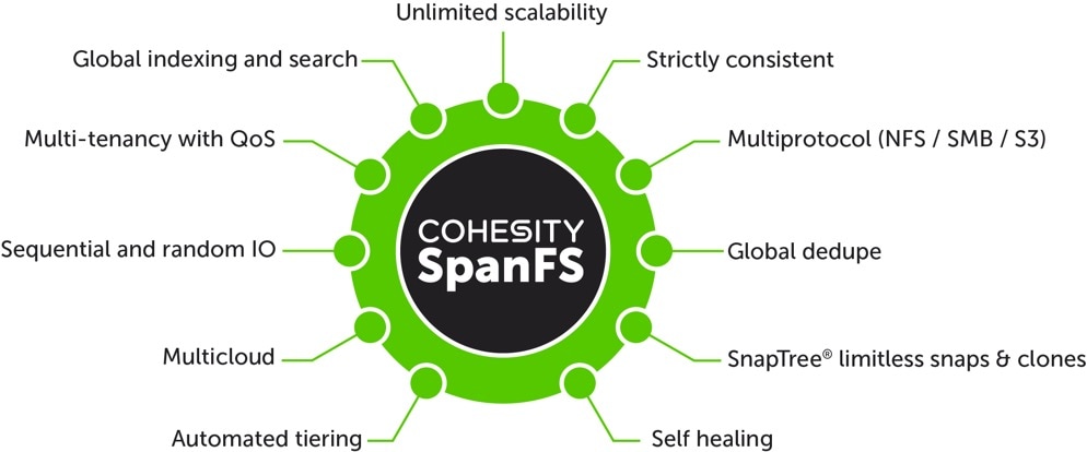
Key SpanFS attributes and implications include the following:
● Unlimited Scalability: Start with as little as three nodes and grow limitlessly on-premises or in the cloud with a pay-as-you-grow model.
● Strictly Consistent: Ensure data resiliency with strict consistency across nodes within a cluster.
● Multi-Protocol: Support traditional NFS and SMB based applications as well as modern S3-based applications. Read and write to the same data volume with simultaneous multiprotocol access.
● Global Dedupe: Significantly reduce data footprint by deduplicating across data sources and workloads with global variable-length deduplication.
● Unlimited Snapshots and Clones: Create and store an unlimited number of snapshots and clones with significant space savings and no performance impact.
● Self-Healing: Auto-balance and auto-distribute workloads across a distributed architecture.
● Automated Tiering: Automatic data tiering across SSD, HDD, and cloud storage for achieving the right balance between cost optimization and performance.
● Multi Cloud: Native integrations with leading public cloud providers for archival, tiering, replication, and protect cloud-native applications.
● Sequential and Random IO: High I/O performance by auto-detecting the IO profile and placing data on the most appropriate media Multitenancy with QoS Native ability to support multiple tenants with QoS support, data isolation, separate encryption keys, and role-based access control.
● Global Indexing and Search: Rapid global search due to indexing of file and object metadata.
Solution Architecture and Requirements
This chapter contains the following:
● Amazon Web Services Account (AWS)
● Storage Snapshot Provider for HyperFlex
The following sections detail the licensing requirements, physical hardware, software revisions, and firmware versions required to deploy Hybrid Cloud solution for archive and disaster Recovery of Cisco HyperFlex cluster with Cohesity on Cisco X-Series modular system and Cohesity on AWS.
Note: The entire document references Cisco HyperFlex as the source Virtual Infrastructure and Cohesity on Cisco UCS X-Series modular system as the on-premises Cohesity Data Cloud cluster. The HyperFlex Cluster can be replaced with any Virtual Infrastructure deployed on VMWare ESXI Servers and the on-premises Cohesity Data Cloud Cluster can be deployed either on a Cisco X-Series modular system or any Cohesity certified Cisco UCS C-Series servers.
Cisco Intersight Licensing
Cisco Intersight uses a subscription-based license with multiple tiers. Each Cisco endpoint (Cisco UCS server, Cisco HyperFlex system, or Cisco UCS Director software) automatically includes a Cisco Intersight Base when you access the Cisco Intersight portal and claim a device.
Cisco Intersight License Tiers
The following are the Cisco Intersight license tiers:
● Cisco Intersight Essentials—Essentials includes ALL functionality of Base with the additional features including Cisco UCS Central and Cisco IMC Supervisor entitlement, policy-based configuration with Server Profiles, firmware management, and evaluation of compatibility with the Hardware Compatibility List (HCL).
● Cisco Intersight Advantage—Advantage offers all features and functionality of the Base and Essentials tiers.
● Cisco Intersight Premier—In addition to the functionality provided in the Advantage tier, Intersight Premier includes full subscription entitlement for Cisco UCS Director at no additional cost.
More information about Intersight Licensing and features supported in each licensing can be found here: https://intersight.com/help/saas/getting_started/licensing_requirements#intersight_licensing
In this solution, using Cisco Intersight Essentials License Tier enables the following:
● Deploying and monitoring of Cisco HyperFlex cluster.
● Configuration of Domain and Server Profiles for Cohesity on Cisco UCS X-Series modular system.
License Status
The Cisco Intersight account license state could be one of the following depending on your subscription status:
● Not Used—This status is displayed when the server count in a license tier is 0.
● In Compliance—The account licensing state is in compliance and all the supported features are available.
● Out of Compliance—The account license status displays Out of Compliance in the following cases:
◦ When not enough valid licenses are available because the subscription has reached the end of term, or you have more servers in the license tier than available licenses.
◦ When the grace period of 90 days is active or expired.
◦ The servers are added to the account but not registered in the Smart Licensing account.
When an account license status moves to Out of Compliance, a grace period of 90 days is triggered. In this period, you can continue to use the premium features, but the account license status remains Out of Compliance. To get back in compliance, you must purchase additional licenses or remove a server from the existing tier or move it to a lower tier. If you do not renew your license within the 90 days, the license state moves to Grace Expired and the license is downgraded to Base-level functionality and the premium features become unavailable. You must register a valid license again to resume using the features.
For example, if an account has a valid license for 20 servers and if you claim another server into the account, the status moves to Out of Compliance and the grace period is initiated. However, you can continue to access the features as before. To restore the In Compliance status, you can move one of the servers to a lower tier (Base/ Essentials/Advantage, as required) from the Actions Menu in the Server Details page, or from the Server /Bulk Actions in the Table view.
Note: After you purchase and activate additional licenses from the Cisco Smart Licensing portal, click the Refresh icon in the Subscription pane to sync the licensing status with that in the portal.
Amazon Web Services Account (AWS)
This solution utilizes AWS account to deploy Cohesity Data Cloud and requires the following:
● An AWS IAM user account, attached to an IAM policy that grants permissions to create the Cohesity Cloud Edition cluster and the permissions to backup and recovery EC2 instances.
● The access key ID and secret access key combination—for the AWS user account.
The following sections detail the physical hardware, software revisions, and firmware versions required to install Cohesity Clusters running on Cisco Unified Computing System. A Cohesity on-premises cluster requires a minimum of three physical nodes deployed either on Cisco UCS X-Series or Cisco C-Series cohesity certified nodes. To allow minimal resiliency during a single node failure, it is recommended to have a minimum of four cohesity certified Cisco UCS nodes.
Table 1 lists the required hardware components and disk options for the Cohesity Data Cloud on Cisco X-Series modular systems.
Table 1. Cisco UCS X-Series Modular System for Cohesity Data Cloud
| Component |
Hardware |
|
| Fabric Interconnects |
Two (2) Cisco UCS 6454 Fabric Interconnects |
|
| Chassis |
Cisco UCS X 9508 Chassis |
|
| Server Node |
4x Cisco UCS X-210C-M6 Server Node for Intel Scalable CPUs |
|
| Processors |
Each server node equipped with two Intel 6326 2.9GHz/185W 16C/24MB |
|
| Memory |
Each server node equipped with 384 GB of total memory using twelve (12) 32GB RDIMM DRx4 3200 (8Gb) |
|
| Disk Controller |
Cisco UCS X10c Compute Pass Through Controller (Front) |
|
| Storage (Each server node) |
OS Boot |
2x M.2 (240GB) with M.2 HW RAID Controller |
| NVMe |
6x 15.3 TB NVMe |
|
| Network (Each Server node) |
Cisco UCS VIC 14425 4x25G mLOM for X Compute Node |
|
| IFM |
2 x UCS 9108-25G IFM for 9508 Chassis |
|
Table 2. Cisco HyperFlex System
| Component |
Hardware |
| Fabric Interconnects |
Two (2) Cisco UCS 6454 Fabric Interconnects |
| Servers |
Four (4) HXAF240C-M5SX converged nodes |
Software Components
Table 3 lists the software components and the versions required for Cisco HyperFlex system, Cohesity Data Cloud and Cisco X-Series modular systems , as tested, and validated in this document.
| Component |
Hardware |
| Cisco HyperFlex |
HyperFlex 5.0.1c-41145 with ESXi 7.0.2-19290878 |
| Cohesity Data Cloud |
6.6.0d_u5_release-20220718_e181c2f1 or later |
| FI 6454 |
4.2(1i)A |
| X210C nodes |
5.0(1c) |
Storage Snapshot Provider for HyperFlex
The Cohesity Data Cloud offers integration with storage-based snapshots, leveraging the native snapshot technologies built directly into the storage arrays, versus using the standard VMware based virtual machine snapshots. Cisco HyperFlex offers native storage-based snapshots, which provide space-efficient and crash-consistent snapshots taken by the underlying Cisco HyperFlex Distributed Filesystem, instead of standard VMware redo-log based snapshots. By using this integration via the Cisco HyperFlex API, the Cohesity protection jobs will take Cisco HyperFlex native snapshots instead of VMware snapshots. In order to use the Cisco HyperFlex API to create native snapshots, the Cisco HyperFlex cluster(s) must be registered as a Storage Snapshot Provider source.
In order for Cohesity Protection Jobs to always use native HX snapshots of the virtual machines running in the Cisco HyperFlex cluster(s), it is important that the virtual machines to be protected not have any existing standard VMware redo-log based snapshots. An existing VMware snapshot will prevent the creation of a subsequent HX native snapshot, and instead all snapshots taken by the Cohesity Data Cloud cluster will continue to be VMware snapshots. In this situation, prior to configuring Cohesity Protection Jobs it is recommended to delete all existing VMware snapshots from the virtual machines running in the Cisco HyperFlex cluster(s), which will be protected by Cohesity using the Storage Snapshot Provider integration.
Procedure 1. Configure Cisco HyperFlex as a Storage Snapshot Provider Source
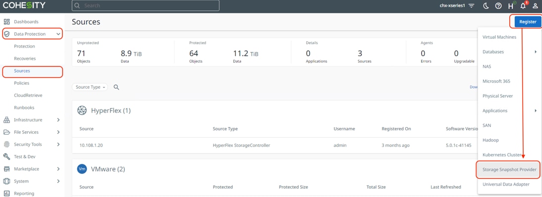
Step 1. Log into the Cohesity Dashboard web page.
Step 2. From the left navigation pane, select Data Protection -> Sources.
Step 3. Click Register and from the drop-down list that appears, click Storage Snapshot Provider.
Step 4. From the Snapshot Storage Provider Type drop-down list, select Storage Snapshot Provider: HyperFlex
Step 5. Enter the hostname or IP address of the Cisco HyperFlex management IP, and an administrative username and password. This must be the roaming or floating management IP address, not the management IP address of any individual Cisco HyperFlex node.
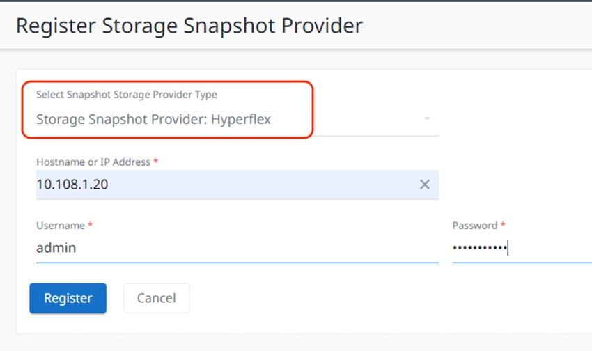
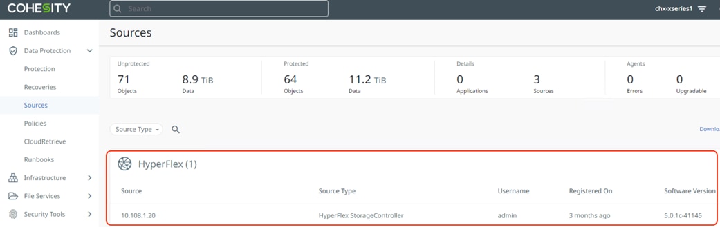
Step 6. Click Register.
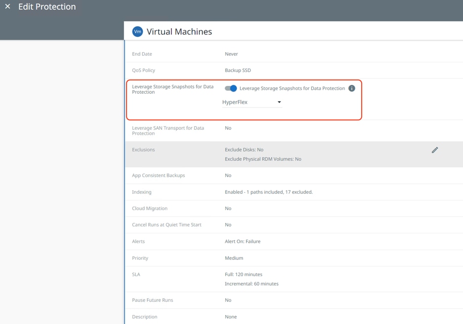
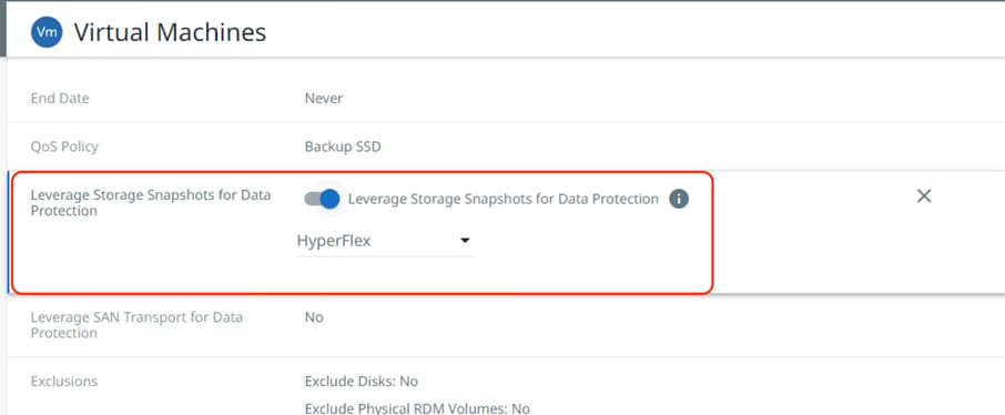
Step 7. During creation of Cohesity Protection Groups, to take advantage of the Cisco Storage Snapshot integration with Cisco HyperFlex clusters, ensure to go to Additional settings, click the Edit link next to “Leverage Storage Snapshots for Data Protection.” Toggle the radio button on and select HyperFlex from the drop-down list that appears. The process is displayed in the following screenshot.
This section details the requirements for the hybrid cloud networking elements that form a core part of this solution.
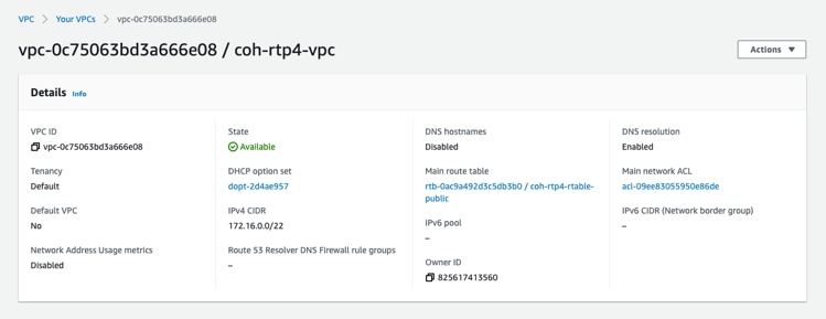
AWS Virtual Private Cloud
You can create dedicated VPC and define the subnet per availability zone, route table and internet gateway.
VPC Endpoints
A VPC endpoint is required to establish the connectivity between the VPC, and AWS supported services without requiring internet gateway, NAT device, VPN connection or direct connect. The VPC is not exposed to public internet and the communication will happen over AWS private network. There are three types of VPC endpoints: Interface endpoints, Gateway Load Balancer endpoints, and Gateway endpoints.
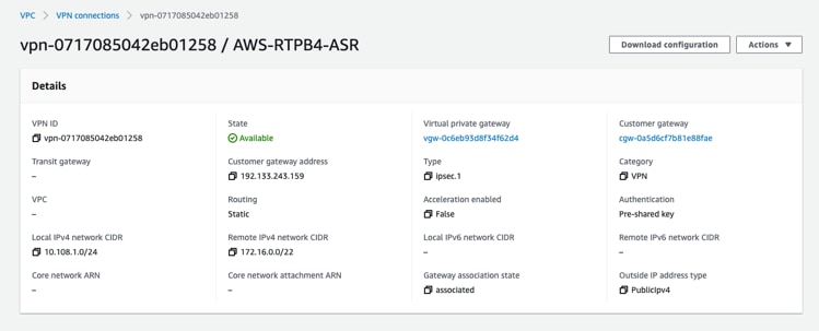
AWS Virtual Private Network
AWS VPN is used in the solution to establish secure connection between network of on-prem Cohesity on Cisco X-Series cluster and the AWS global network. AWS Site-to-Site VPN creates encrypted tunnels between your network and your Amazon Virtual Private Clouds or AWS Transit Gateways.
AWS Direct Connect
The VPN connectivity utilizes the public internet, which can have unpredictable performance and can possess some security concerns. AWS direct connect bypass the public internet and establishes a secure dedicated connection from op-prem to AWS. AWS direct connect is a great option for customers that are seeking secure, low latency connectivity into AWS.
Note: This solution does not utilize AWS Direct Connect, if you already have AWS direct connect then the same connection can be used to establish communication between on-prem Cohesity cluster and Cohesity Cloud Edition.
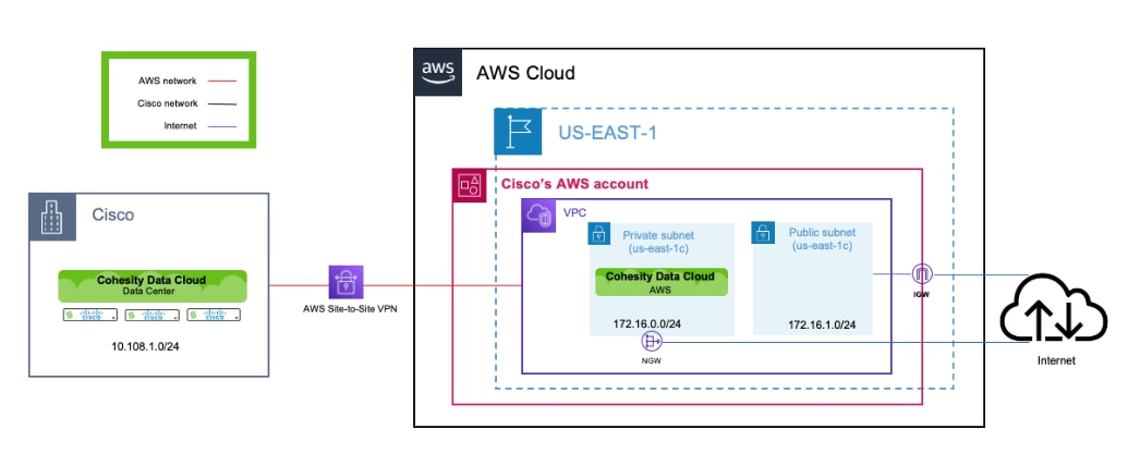
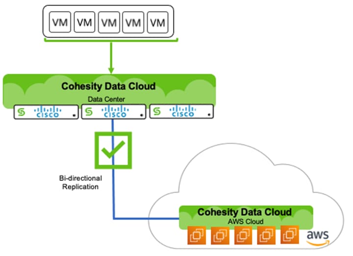
Figure 12 illustrates the solution architecture for Backup, Archive and Disaster Recovery Virtual Infrastructure deployed either on Cisco HyperFlex systems or any converged or hyper-converged systems.
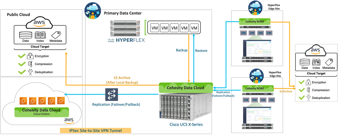
Cisco Intersight cloud operations platform manages the deployment and operations of, Cisco HyperFlex Infrastructure, Cisco X-Series modular systems HyperFlex Edge sites and Cohesity certified C-Series Remote Office Branch Office (ROBO) node. Cohesity Helios manages the operations of Cohesity Data Platform deployed on Cisco X-Series All NVMe nodes and Cohesity cloud edition deployed on AWS.
The Data Plane is created between the Cohesity Data Cloud cluster running on Cisco X-Series All NVMe nodes and Cohesity Data Cloud that runs on AWS by leveraging a secure site-to-site VPN connection.
The archive and replication policies are created through Cohesity Data Cloud which are attached to Cohesity Data Protection groups, leveraged to protect Virtual Infrastructure deployed on Cisco HyperFlex.
Solution Deployment and Validation
This chapter contains the following:
● Cisco Intersight Configuration
● Cisco HyperFlex Platform Configuration
● AWS Infrastructure Configuration
● Configure Cisco X-Series System to Host Cohesity Data Cloud
● Cohesity Data Cloud Configuration for Backup, Archive and Disaster Recovery to AWS
This section describes the high-level steps to successfully validate deployment of Disaster Recovery and Archival solution in an Hybrid Cloud environment. This protects the virtual infrastructure deployed on Cisco HyperFlex platform with Cohesity Data Cloud deployed on Cisco X-Series modular system and Cohesity Data Cloud deployed in AWS.
The high-level steps are:
● Cisco Intersight Configuration
◦ Create and configure Cisco Intersight account
● Cisco HyperFlex platform Configuration
◦ Configure UCS managed HyperFlex nodes
◦ Claim and install HyperFlex platform from Cisco Intersight
◦ Deploy Virtual Machines for protection through Cohesity Data Platform
● AWS Infrastructure Configuration
◦ Configure Site-to-Site VPN connectivity between AWS and Cohesity Data Protection Infrastructure
● Configure Cisco X-Series system to host Cohesity Data Cloud
◦ Claim from Intersight, Cisco X9508 chassis with minimum of three (3) Cohesity certified X210C All NVMe nodes
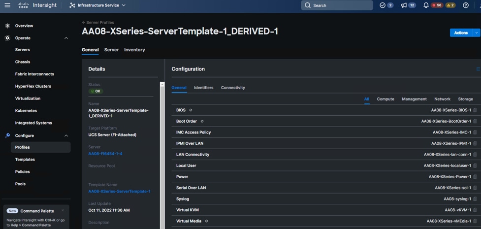
◦ Configure Domain Profile, Chassis Profile and Server Profile from Intersight
◦ Install Cohesity OS from Intersight and configure Cohesity Cluster
● Cohesity Data Cloud Configuration
◦ Configure S3 target for archival and recovery of Virtual Infrastructure
◦ Deploy Cohesity Data Cloud in AWS
◦ Configure Remote targets between on-prem Cohesity Data Cloud Cluster and Cohesity Data Cloud cluster deployed in AWS
Cisco Intersight Configuration
Procedure 1. Create an account in Cisco Intersight
Note: Skip this step if you already have an Intersight account.
The procedure to create an account in Cisco Intersight is explained below. For more details, go to: https://intersight.com/help/saas/getting_started/create_cisco_intersight_account
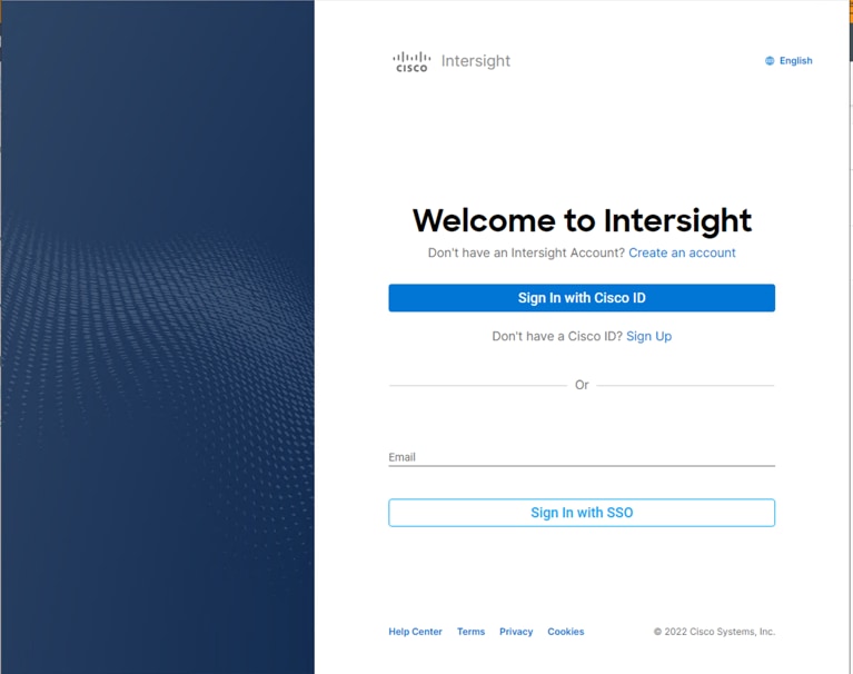
Step 1. Visit https://intersight.com/ to create your Intersight account. You must have a valid Cisco ID to create a Cisco Intersight account.
Step 2. Click Create an account.
Step 3. Sign-In with your Cisco ID.
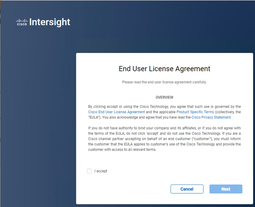
Step 4. Read the End User License Agreement and select I accept and click Next.
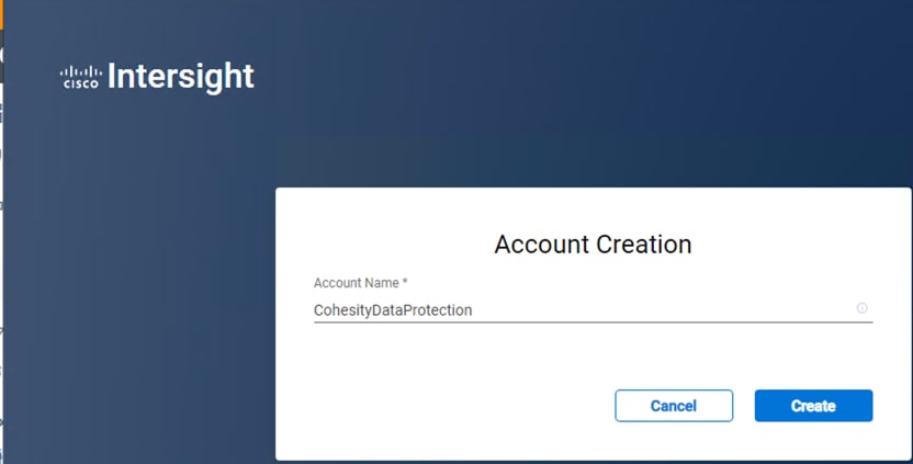
Step 5. Provide a name for the account and click Create.
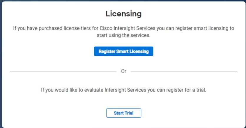
Step 6. Register for Smart Licensing or Start Trial.
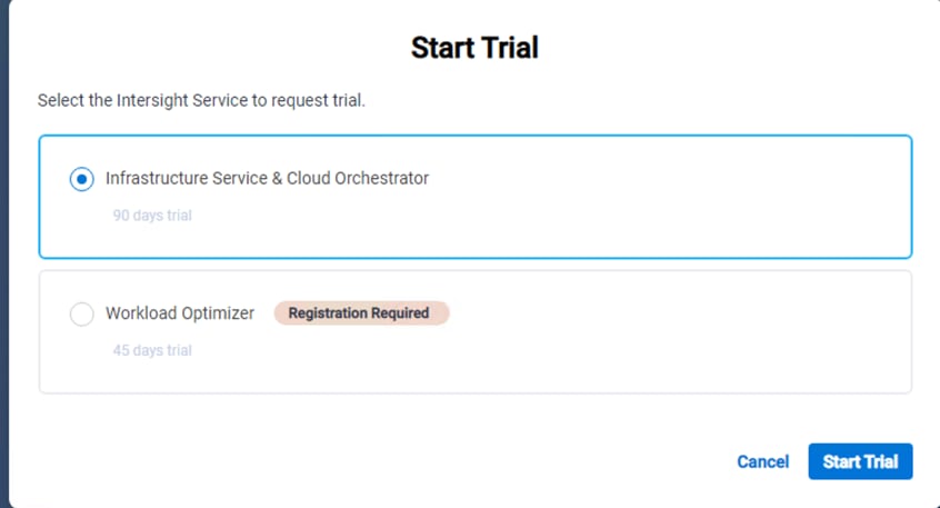
Step 7. Select Infrastructure Service & Cloud Orchestrator and click Start Trial.
Note: Go to: https://intersight.com/help/saas to configure Cisco Intersight Platform.
Cisco HyperFlex Platform Configuration
This solution elaborates on the protection of the Virtual Infrastructure deployed on Cisco HyperFlex platform. To deploy and configure Cisco HyperFlex, refer to the Cisco HyperFlex HX-Series Install and Upgrade Guides.
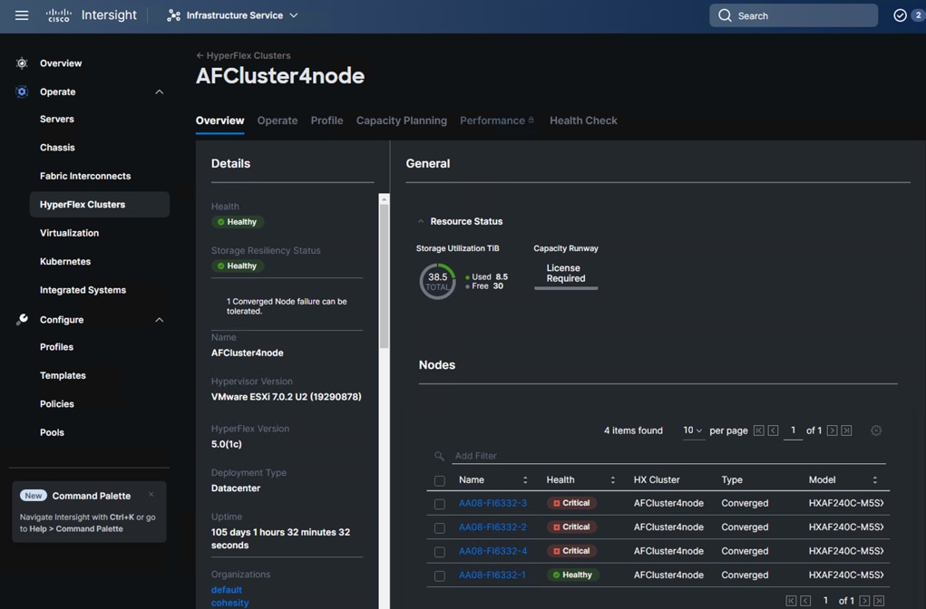
Figure 13 illustrates a pre-configured Cisco HyperFlex system configured through Cisco Intersight.
AWS Infrastructure Configuration
Procedure 1. Configure AWS Environment for Cohesity Data Cloud Platform in AWS
Step 1. Create AWS VPC.
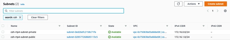
Step 2. Create subnets in the VPC.
Note: For this solution, a private subnet and public subnet were created. The private subnet is connected to the on-premise environment. The public subnet was used to provide external access to the environment. The Cohesity Data Cloud Platform in AWS was deployed in the private subnet.
Step 3. Configure AWS Site-to-Site VPN between the on-premise environment and AWS VPC.
Note: It is recommended to use either an AWS DirectConnect or AWS VPN between the on-premise environment to provide a secure connection.
Configure Cisco X-Series System to Host Cohesity Data Cloud
The Cisco UCS® X-Series with Cisco Intersight™ is a modular system managed from the cloud. The Cisco UCS X-Series provides functionalities of both blade and rack servers by offering compute density, storage capacity, and expandability in a single system, embracing a wide range of workloads in your data center.
Cohesity DataPlatform is certified on Cisco X-Series leveraging all NVME X210C nodes. Cohesity cluster requires a minimum of 3 nodes, but it is suggested to have at least four X210c nodes , with dual socket Intel processor and 6x 15.3 TB NVMe per node
For the step-by-step process to successfully configure the Cisco UCS X-Series with Cohesity DataPlatform, refer to the Cohesity X-Series Setup Guide.
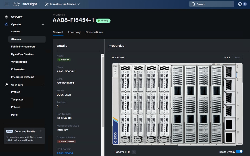
Figure 16 illustrates Cisco X-Series configured for Cohesity DataPlatform.
Cohesity Data Cloud Configuration for Backup, Archive and Disaster Recovery to AWS
Cohesity Data Cloud allows backup of virtual Infrastructure hosted on Cisco HyperFlex to Cohesity Data Cloud configured on Cisco X-Series modular system. The backup on on-prem cluster are replicated to Cohesity Data Cloud deployed in AWS. The S3 target on AWS enables archival of backups existing either on on-prem Cohesity Cluster or on Cohesity certified Cisco C-Series ROBO nodes deployed on the edge sites. For the step-by-step process to deploy Cohesity Cloud Edition on AWS , refer to the AWS Cloud Edition Setup Guide.
Procedure 1. Enable Solution Use Case
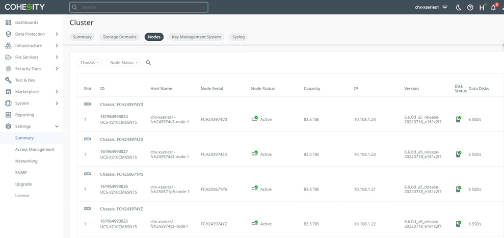
Step 1. Verify registration of Cisco HyperFlex and vCenter on Cohesity Data Cloud Cluster deployed on Cisco X-Series modular system
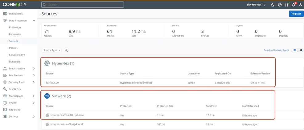
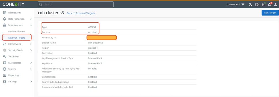
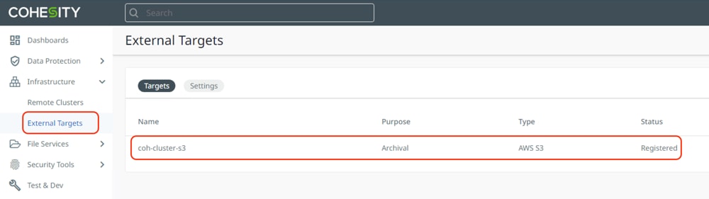
Step 2. Verify S3 bucket registered as external target on Cohesity Data Cloud Cluster.
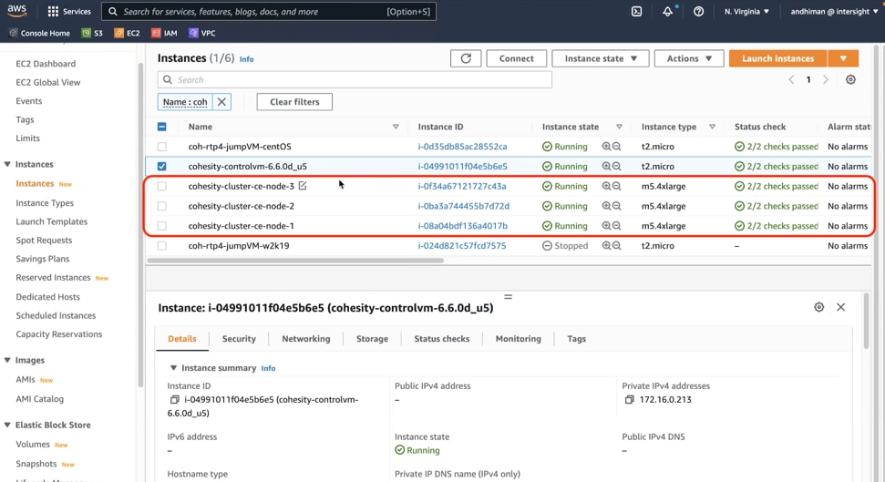
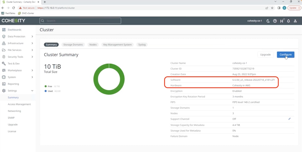
Step 3. Verify Cohesity Data Cloud deployed in AWS.
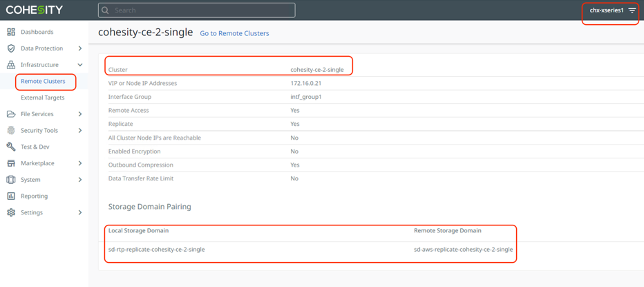
Step 4. Verify Cohesity Data Cloud Cluster deployed in AWS is configured as Remote Cluster in on-prem Cohesity Data Cloud Cluster deployed on Cisco X-Series system.
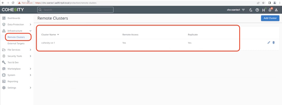
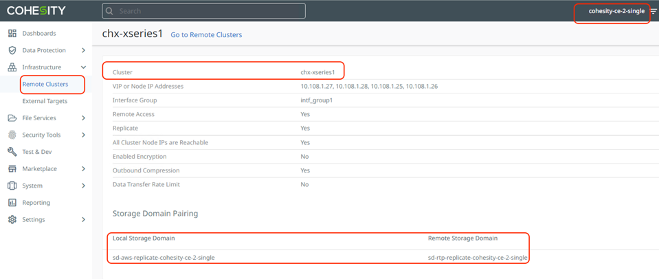
Step 5. To enable two-way replication, verify Cohesity on-prem cluster is configured as Remote Cluster on Cohesity Data Cloud Cluster deployed in AWS.
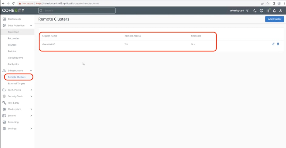
When the configuration is complete, proceed to the next section and validate backup, archive and disaster recovery of workloads protected on Cohesity on-prem cluster deployed on Cisco X-Series systems.
Use Case Validation for Disaster Recovery in Hybrid Cloud Environment
This chapter contains the following:
● Cohesity Recovery from S3 to Primary Data Center
● Recovery from S3 to New Cohesity Cluster on Primary or Edge Location
● Replication and Recovery to Cloud (Failover)
● Replication and Recovery Back to On-Prem Data Center Cloud (Failback)
The key scenarios validated are:
● Recovery from S3 to primary Data Center. This use case includes Archival of Backups from Cohesity Data Cloud on Cisco X-Series to S3 and recovery to same Cohesity cluster.
● Recovery from S3 to new Cohesity Cluster on primary or edge location. This use case includes Archival of Backups from Cohesity Data Cloud on Cisco X-Series to S3 and recovery to a new location existing either on multi-node Cohesity cluster or Cohesity Virtual Edition on Edge location. This utilizes Cohesity CloudRetrieve feature.
● Replication and Recovery to Cloud (Failover). This use case is best deployed when you are looking for lower RPOs and RTOs but involves higher cost due to running Cohesity Data Cloud deployed in AWS. It includes replication of backups from primary Data Center to Cohesity Data Cloud cluster deployed in AWS. During failure of primary Data Center you can recover their Virtual Infrastructure to AWS.
● Replication and Recovery to on-prem Data Center (Failback). This use case is an extension to Failover, wherein customers have an option to get the data back to primary Data Center or Edge location from Cohesity Data Cloud cluster deployed in AWS. This is particularly beneficial for use cases wherein the primary Data center or Edge location has recovered from failure or maintenance.
Cohesity Recovery from S3 to Primary Data Center
Recovery the Virtual Infrastructure from S3 provides low cost for cloud services but involves high RTO.
Note: Since backing up the Virtual Infrastructure utilizes low performing S3 bucket, recovery the virtual machines back to the primary data center may take considerable time.
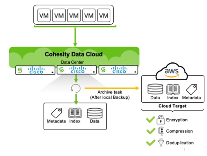
Figure 19 illustrates the process of archiving the local backups on the primary data center or edge locations.
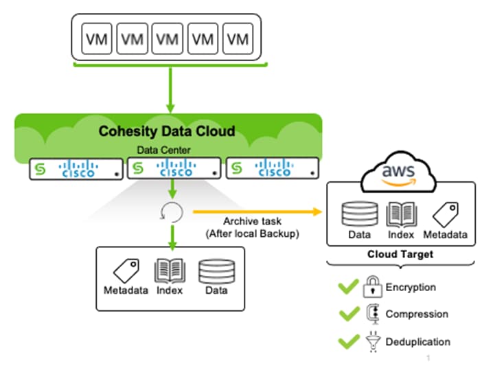
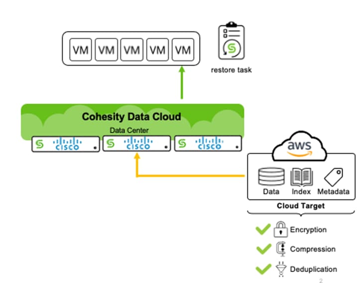
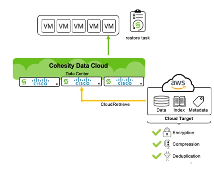
Figure 20 illustrates the recovery process from the S3 archive back to the primary data center or edge locations.
Procedure 1. Validate the recovery of VMs from the S3 bucket on AWS
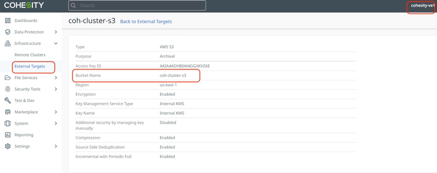
Step 1. Ensure the S3 archive target is registered with Cohesity Data Cloud cluster deployed on Cisco X-Series system.
Step 2. Create the Protection Group to backup and archive virtual machine hosted Cisco HyperFlex. Create the Cohesity Protection Policy with S3 enabled.
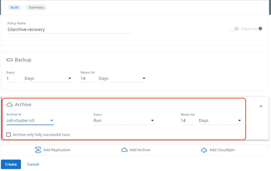
Step 3. Enable backup using Cisco HyperFlex Snapshot.
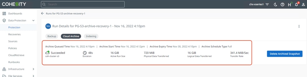
Step 4. Run the Protection Group and ensure the backup to the local Cohesity cluster and that the S3 archive to AWS succeeds.
Step 5. Go to Recovery tab on Cohesity dashboard and identify the protection group to be recovered and select the S3 archive target as the source for recovery.
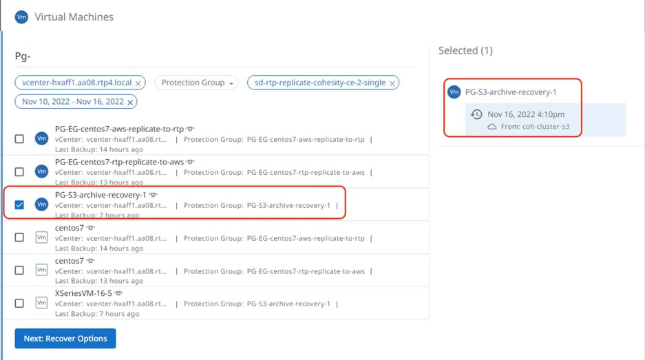
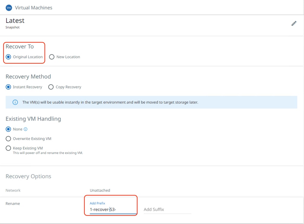
Step 6. Under Recover To, select Original Location and click Recover.
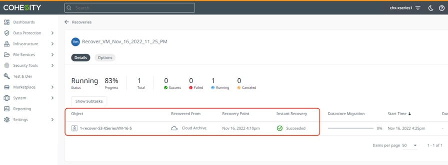
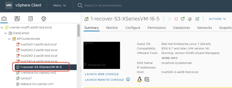
Step 7. When the data from S3 bucket is copied to the primary Cohesity Cluster, the Instant Recovery starts and the VM is instantiated on the Cisco HyperFlex Cluster.
Recovery from S3 to New Cohesity Cluster on Primary or Edge Location
Cohesity Data Cloud allows you to recover to any Cohesity Data Cloud cluster from a S3 archive data. This is beneficial during recovery to any Cohesity cluster from failure of the primary data center or edge location disaster.
With this feature, you can enable disaster recovery wherein the edge site or a primary site cannot be recovered. As the S3 archive involves low cost on AWS, you can use this for its non-mission critical workloads, with a caveat that it will involve high RTOs.
Figure 21 illustrates the process of archiving the local backups on the primary data center or edge locations.
Follow the steps in Cohesity Recovery from S3 to Primary Data Center to configure Backup and Archive. Thereafter you can register the same S3 bucket to a new Cohesity Data Cloud cluster and recover from the archive. Figure 23 details the registration of the S3 bucket to the new Cohesity Data Cloud Cluster.
Procedure 1. Recover from the S3 Bucket to new the Cohesity Cluster
Step 1. Go to the CloudRetrieve tab on the Cohesity Data Cloud Dashboard and start searching by selecting the appropriate registered S3 bucket. You can search with various options, such as Protection Group Name, or cluster name.
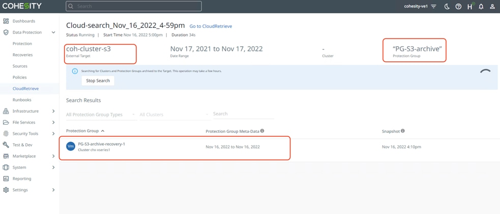
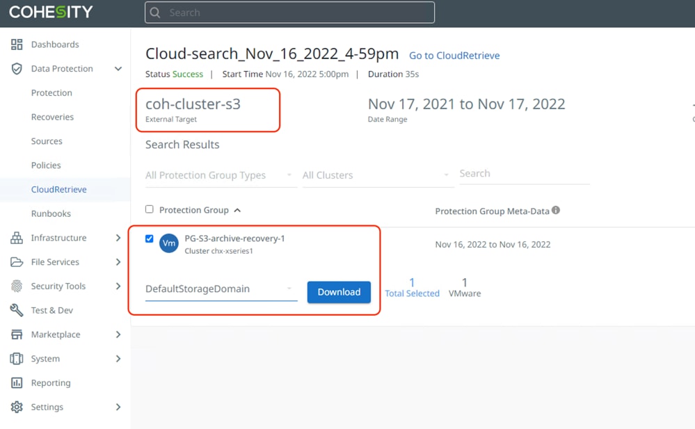
Step 2. Select the Protection Group and select an appropriate Storage Domain existing on the Cohesity Data Cloud and click Download. This allows the entire Protection Group to be downloaded from S3 bucket to new Cohesity Cluster.
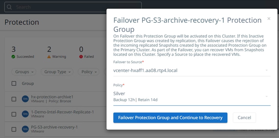
The downloaded Protection Groups are accessible as 'Failover Ready' Protection Groups on the Protection Groups page. You can perform Recovery or Clone.
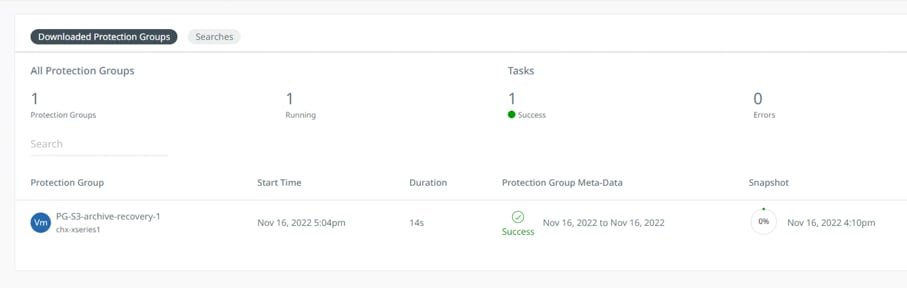
The Protection Group is downloaded to the Cohesity Data Cloud and is ready to be recovered to the HyperFlex Edge cluster and is protected with the new Cohesity Protection Policy.
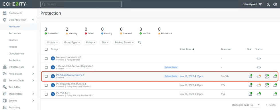
You can failover the Protection Group and Recover VM to a new source HyperFlex Edge cluster.
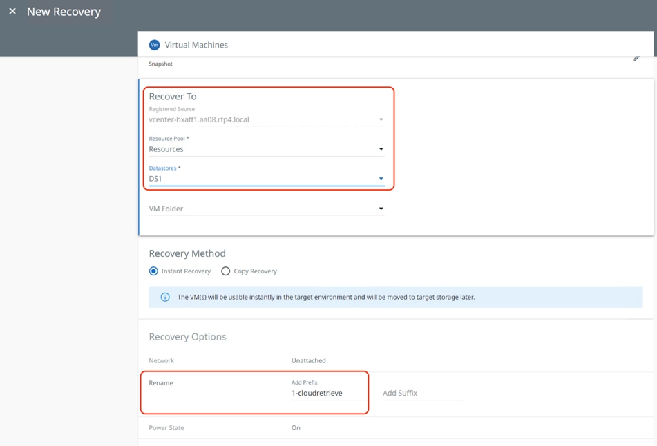
The VM is instantly recovered to the HyperFlex Cluster.
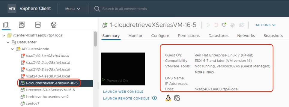
This procedure provides a disaster recovery scenario wherein the entire Data Center fails and cannot be recovered. It allows recovery of the Virtual Infrastructure to a new HyperFlex Cluster.
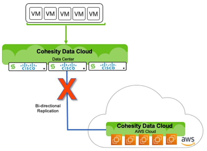
Replication and Recovery to Cloud (Failover)
This use case is best deployed when you want lower RPOs and RTOs but involves higher cost due to running Cohesity Data Cloud deploy in AWS. It includes replication of backups from primary Data Center to Cohesity Data Cloud deployed in AWS. During failure of primary Data Center customers can recover their Virtual Infrastructure to AWS.
Figure 24 illustrates the Replication of backups between on-prem Cohesity Data Cloud Cluster to Cohesity Data Cloud cluster deployed in AWS.
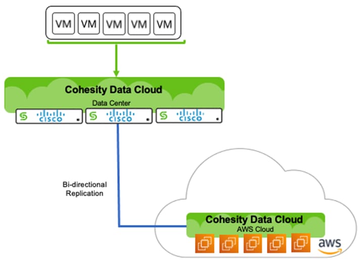
If there is a failure of on-premises cluster, the Virtual Infrastructure can be failed over to AWS which will allow conversion of VM data to EC2 instance.
Procedure 1. Ensure Successful Failover from Cohesity Data Cloud On-Prem Cluster to Cohesity Data Cloud Deployed in AWS
Step 1. Configure Cohesity on-prem cluster and the Cohesity Data Cloud deployed in AWS as Remote Cluster to each other.
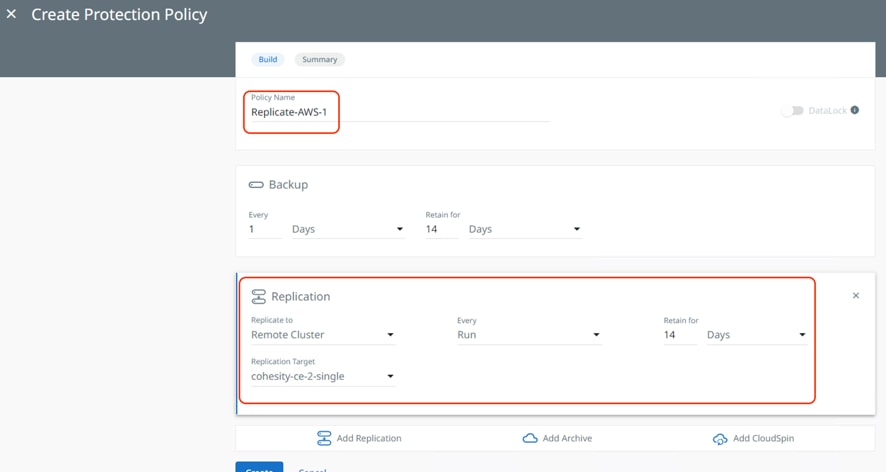
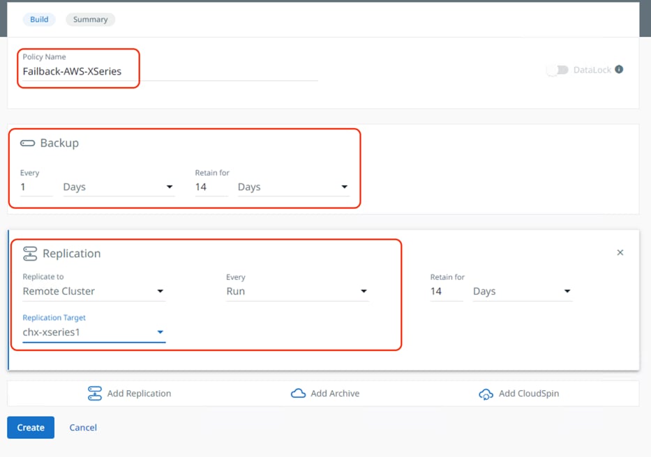
Step 2. Create a Cohesity Protection Policy with Replication to Cohesity Data Cloud deployed in AWS.
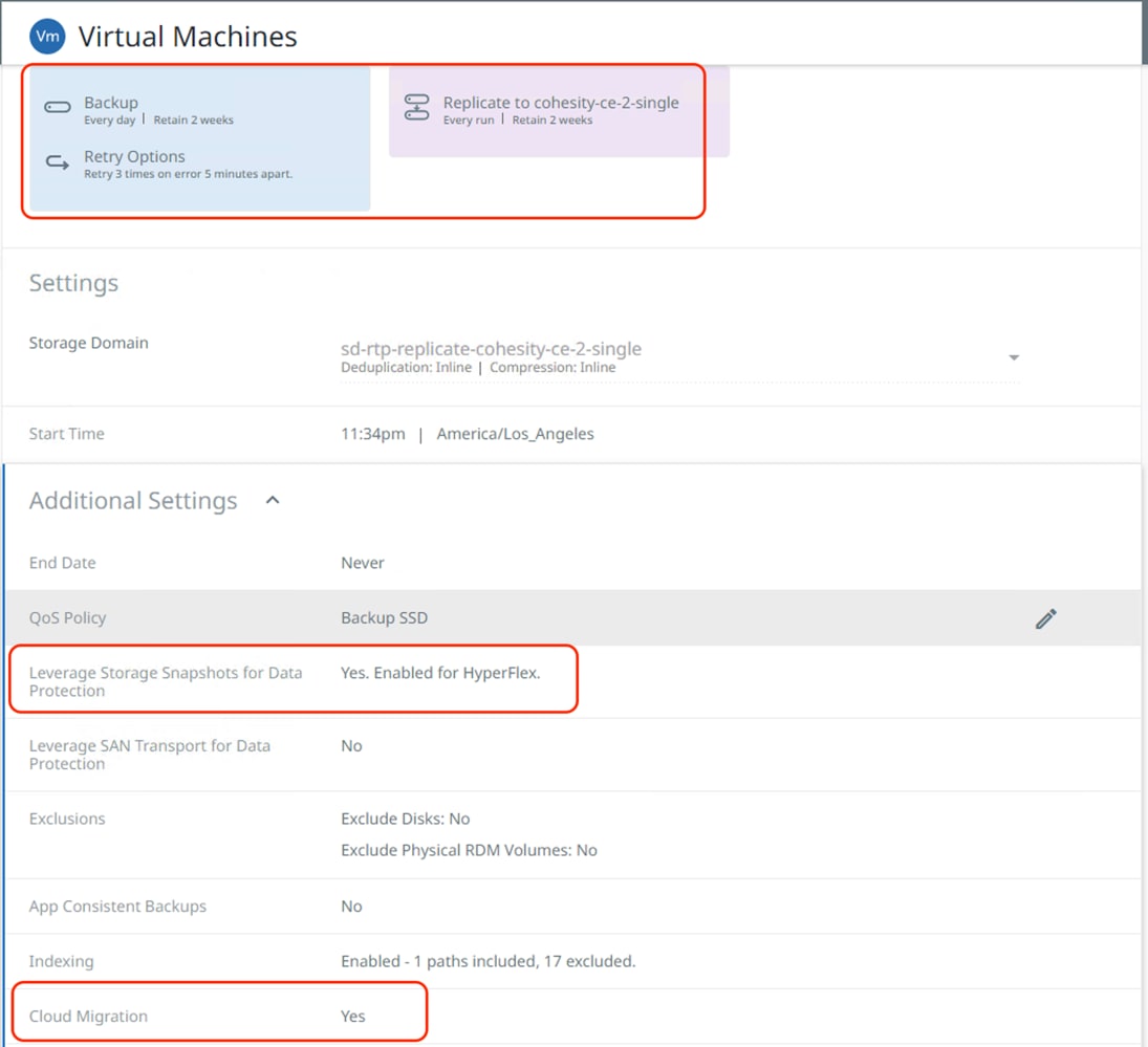
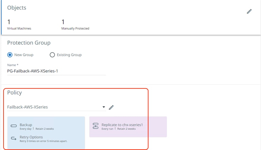
Step 3. Create and execute Protection Group to protect Virtual Infrastructure on HyperFlex with Protection Policy defined for Replication to Cohesity Data Cloud deployed in AWS, ensure Hyperflex snapshot and Cloud migration options are enabled.
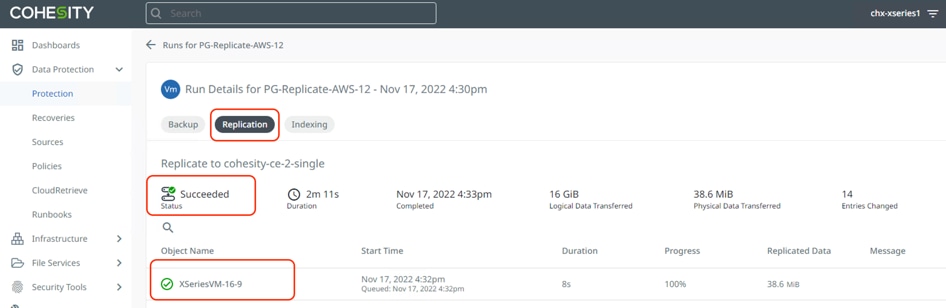
Step 4. Ensure backup and replication is completed successfully.
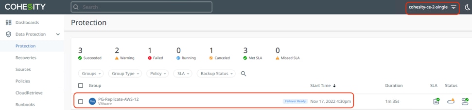
Step 5. The Cohesity Data Cloud deployed in AWS displays the same Protection Group name as failover ready, and the VM replicated is ready to be failed over during any disaster on the on-premises Data Center.
Step 6. Assuming the primary Data Center has failed, failover the replicated VM to AWS, thus demonstrating a disaster recovery with failover to AWS workflow.
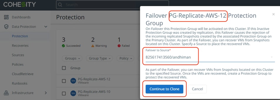
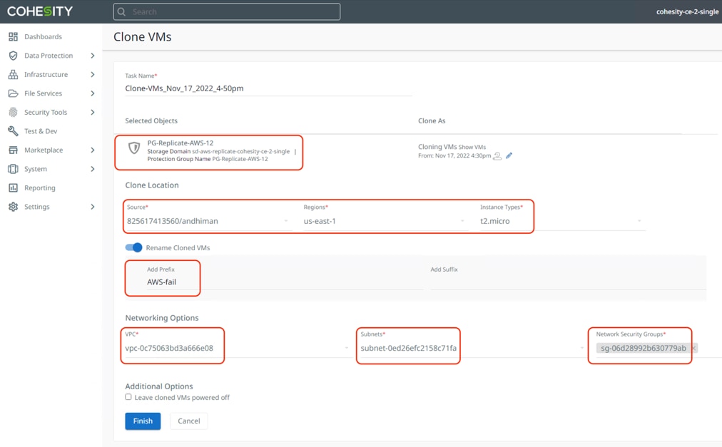
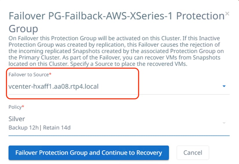
Step 7. Select Failover of the Protection Group on Cohesity Data Cloud deployed in AWS cluster and select Failover source as AWS configured with correct IAM userID, click Continue to Clone.
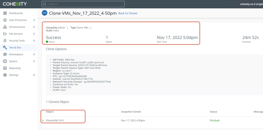
Step 8. For restoration to AWS, select the appropriate region, instance type, VPC, subnet and network security group and click Finish. This will instantiate an EC2 instance of the VM replicated from the on-premises Data Center to Cohesity Data Cloud deployed in AWS.
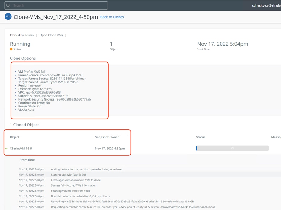
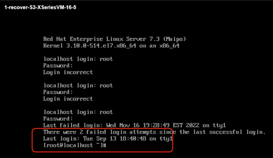
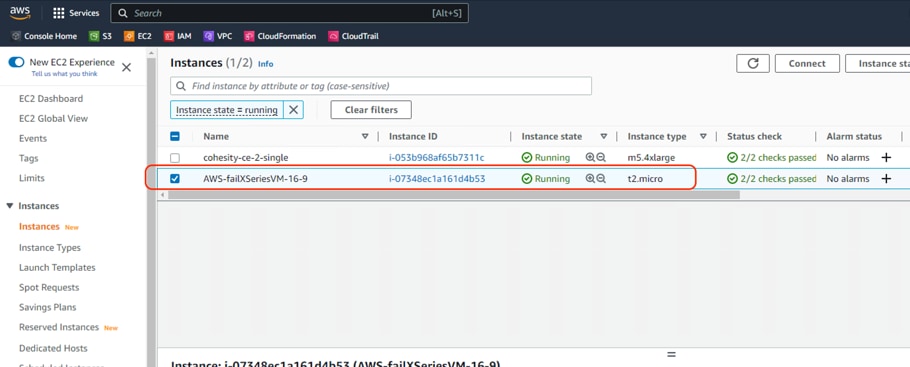
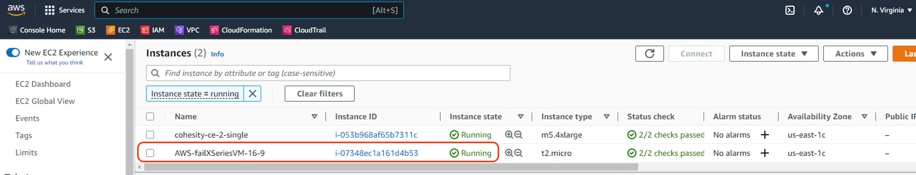
Step 9. When the recovery is complete, you can go to EC2 console and login to the VM failed over from on-premises Data Center. Successful recovery to an EC2 is shown below.
Replication and Recovery Back to On-Prem Data Center Cloud (Failback)
This use case elaborates on the validation for failback of Virtual Infrastructure recovered on Public Cloud, such as AWS. In the previous section, a successful validation for failover of Virtual Infrastructure to AWS during disaster was demonstrated. Replication with Failover to AWS and Failback to on-prem data center is best suited for mission critical workloads requiring low RTO and RPO.
The high-level overview of the failback process is illustrated in Figure 25.
Procedure 1. Failback Virtual Infrastructure to On-Prem Cohesity Data Cloud Cluster and Recovery to HyperFlex Platform
Step 1. Ensure the VM is successfully failed over to AWS.
Step 2. Validate Remote Cluster configuration on Cohesity Data Cloud deployed in AWS and Cohesity Data Cloud deployed on X-Series Cluster.
Step 3. Configure Cohesity Protection policy to the backup Virtual Infrastructure on AWS to Cohesity Data Cloud deployed in AWS and replication to Cohesity Data Cloud deployed on X-Series All NVMe nodes.
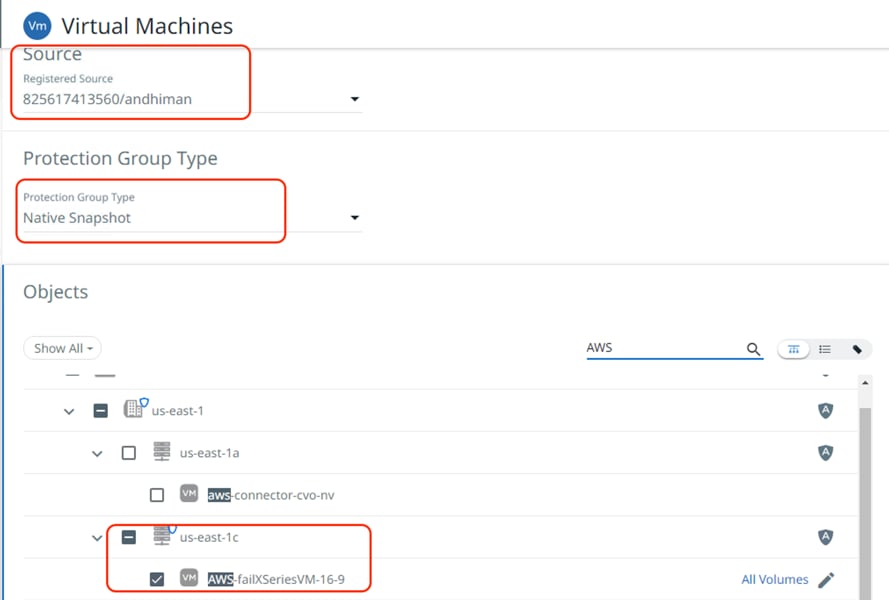
Step 4. Configure a protection group on Cohesity Data Cloud deployed in AWS for backup and replication of failed over VM. Select the Protection Policy created for backup and Replication.
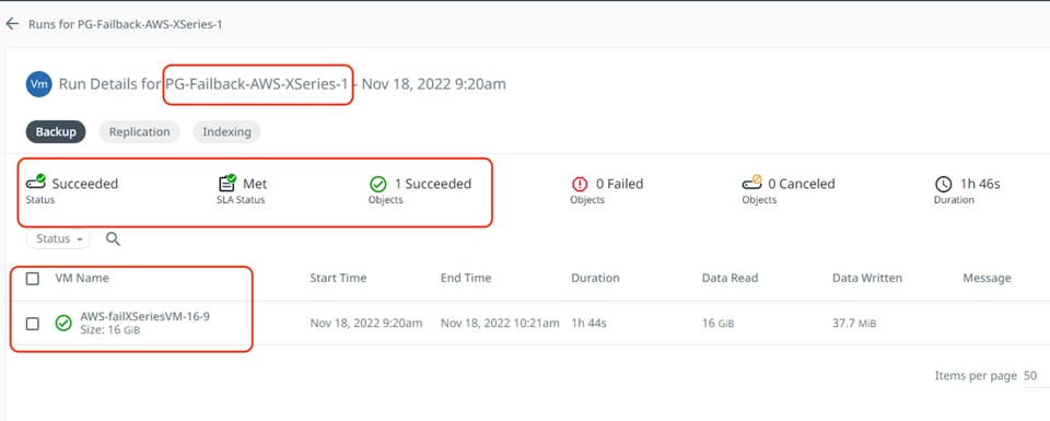
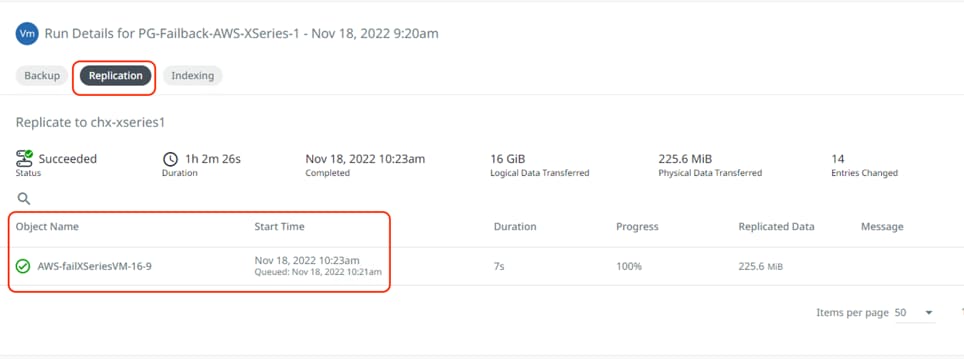
Step 5. Ensure the backup and replication task completed successfully and the same Protection Group is visible as failover ready in on-premises cluster deployed on Cisco X-Series nodes.
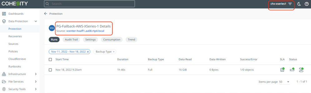
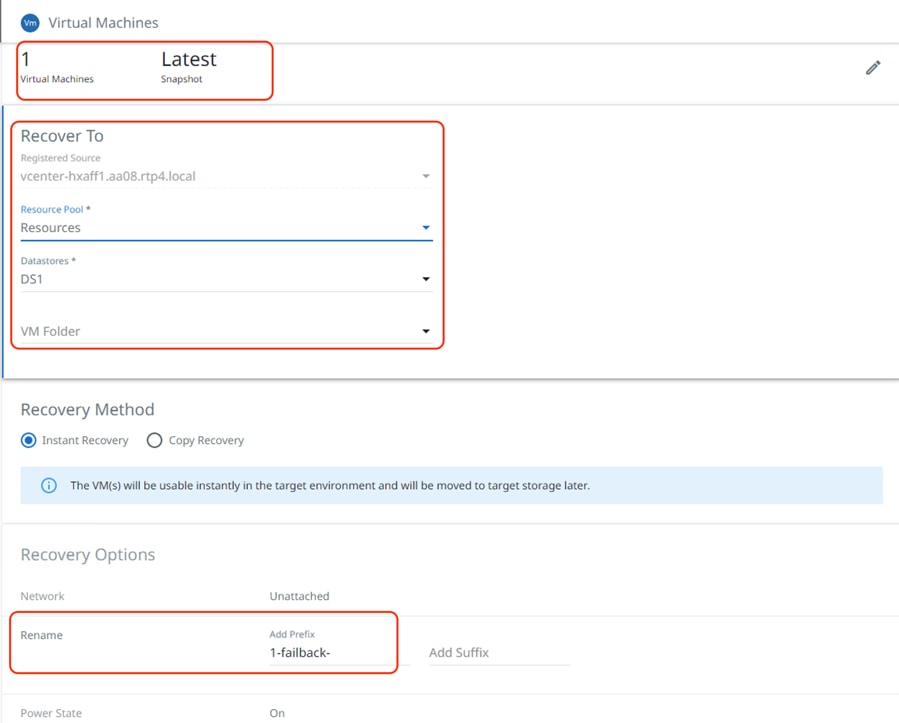
Step 6. When the replication to on-prem cluster completes successfully, failover the Protection Group and restore the VM on HyperFlex Cluster located in the on-prem data center.
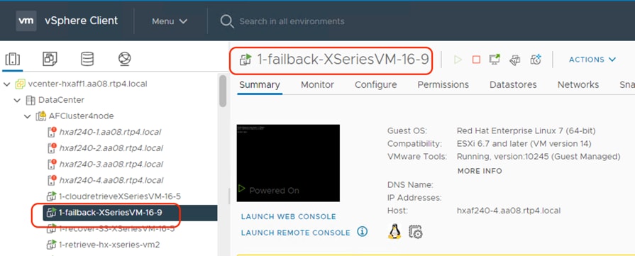
The image below illustrates the recovery of failed back VM from AWS to on-premises HyperFlex cluster:
Cohesity Certified Cisco UCS Nodes
This solution utilizes 4x X210C All NVMe nodes configured on Cisco UCS X-Series modular system. Along with the present configuration, Cisco and Cohesity have certified solutions with different capacity points available on Cisco UCS C Series Rack Servers and Cisco UCS S3260 Storage servers. This allows you to select your configuration based on key characteristics such as:
● Total Capacity
● Workload configurations such as Data Protection and File Services
● Performance requirements based on Cisco X-Series modular system with All NVMe X210C nodes, Cisco UCS C220 M6 All Flash or C240 M6 LFF HDD (12 and 16 drives) configurations.
● Single node deployments for Remote offices and Branch offices (ROBO)
● Cohesity SmartFiles solution with Cisco UCS S3260 dual node configuration
Table 4 lists the Cohesity certified nodes on Cisco UCS Platform.
Table 4. Cohesity Certified Cisco UCS Nodes
| Solution Name |
Cisco UCS Platform |
Capacity per Node |
Caching SSDs/NVMe per Node |
| Cohesity X-Series Al NVMe nodes |
Cisco UCS X9508 platform |
91.8 TB |
|
| Cohesity-C240 M6 LFF-Nodes |
Cisco UCS C240 M6 LFF Rack Server with 12 and 16 drive options |
48 TB |
3.2 TB |
| 64 TB |
3.2 TB |
||
| 96 TB |
6.4 TB |
||
| 128 TB |
6.4 TB |
||
| 144 TB |
6.4 TB |
||
| 192 TB |
6.4 TB |
||
| 216 TB |
12.8 TB |
||
| 288 TB |
12.8 TB |
||
| Cohesity-C220 M5-ROBO-8TB-and-16TB-Nodes |
Cisco UCS C220 M5 LFF Rack Server |
8 TB |
1920 GB |
| 16 TB |
1920 GB |
||
| Cohesity-C220-All-NVMe-Nodes |
Cisco UCS C220 M6 All NVMe Rack Server |
76 TB |
|
| Cohesity-S3260-210TB-294TB-420TB-588TB-704TB-768TB-Node |
Cisco UCS S3260 M5 Storage Server |
210 TB |
12.8 TB |
| 294 TB |
12.8 TB |
||
| 420 TB |
12.8 TB |
||
| 588 TB |
12.8 TB |
||
| 704 TB |
12.8 TB |
||
|
|
Cisco UCS S3260 M5 dual node Storage Server (SmartFiles) |
768 TB |
25.6 TB |
| 384 TB ** |
12.8 TB |
Note: **384 TB half populated S3260 chassis can only be purchased in conjunction with a dual node 768TB configuration.
Anil Dhiman, Technical Leader, Technical Marketing Engineering, UCS Solutions, Compute & Networking Group, Cisco Systems, Inc.
Anil Dhiman has nearly 20 years of experience specializing in Data Center solutions on Cisco UCS servers, and Performance Engineering of large-scale enterprise applications. Over the past 11 years, Anil has authored several Cisco Validated Designs for Enterprise Solutions on Cisco Data Center Technologies. Currently, Anil's focus is on Cisco’s portfolio of Hyperconverged Infrastructure and Data Protection Solutions.
Damien Philip, Principal Solutions Architect, Cohesity
Edwin Galang, Cloud Solutions Architect, Cohesity
Acknowledgements
For their support and contribution to the design, validation, and creation of this Cisco Validated Design, the authors would like to thank:
● Rohit Mittal, Product Manager, Cisco Systems, Inc.
● Francesca Harbert, Director, Cisco Global Alliance, Cohesity
● Eleonor Lee, Senior Product Marketing Manager - Alliances Solutions
This appendix contains the following:
● Appendix A - Bill of Materials
● Appendix B - Recommended for You
Appendix A – Bill of Materials
Table 5 provides an example Bill of Materials used for four (4) node Cohesity DataPlatform cluster deployed on a single Cisco UCS X-Series chassis, along with a pair of Cisco Fabric Interconnects, used in the testing and reference design described in this document.
Table 5. Cohesity FileServices (4 nodes) on Cisco UCS Bill of Materials
| Cisco X-Series estimate (4 All NVMe nodes) for Cohesity DataPlatform |
|||
| 1.0 |
UCSX-M6-MLB |
UCSX M6 Modular Server and Chassis MLB |
1 |
| 1.1 |
DC-MGT-SAAS |
Cisco Intersight SaaS |
1 |
| 1.1.1 |
DC-MGT-SAAS-EST-C |
Cisco Intersight SaaS - Essentials |
4 |
| 1.1.2 |
SVS-DCM-SUPT-BAS |
Basic Support for DCM |
4 |
| 1.1.3 |
DC-MGT-IMCS-1S |
IMC Supervisor - Advanced - 1 Server License |
4 |
| 1.1.4 |
DC-MGT-UCSC-1S |
UCS Central Per Server - 1 Server License |
4 |
| 1.2 |
UCSX-9508-U |
UCS 9508 Chassis Configured |
1 |
| 1.2.0.1 |
CON-OSP-UCSX95U8 |
SNTC-24X7X4OS UCS 9508 Chassis Configured |
1 |
| 1.2.1 |
UCSX-CHASSIS-SW |
Platform SW (Recommended) latest release for X9500 Chassis |
1 |
| 1.2.2 |
UCSX-9508-FSBK |
UCS 9508 Chassis Front Node Slot Blank |
4 |
| 1.2.3 |
UCSX-9508-CAK |
UCS 9508 Chassis Accessory Kit |
1 |
| 1.2.4 |
UCSX-9508-RBLK |
UCS 9508 Chassis Active Cooling Module (FEM slot) |
2 |
| 1.2.5 |
UCSX-9508-ACPEM |
UCS 9508 Chassis Rear AC Power Expansion Module |
2 |
| 1.2.6 |
UCSX-9508-KEY-AC |
UCS 9508 AC PSU Keying Bracket |
1 |
| 1.2.7 |
UCSX-210C-M6 |
UCS 210c M6 Compute Node w/o CPU, Memory, Storage, Mezz |
4 |
| 1.2.7.0.1 |
CON-OSP-UCSX210C |
SNTC-24X7X4OS UCS 210c M6 Compute Node w/o CPU, Memory |
4 |
| 1.2.8 |
UCSX-X10C-PT4F |
UCS X10c Compute Pass Through Controller (Front) |
4 |
| 1.2.9 |
UCSX-V4-Q25GML |
UCS VIC 14425 4x25G mLOM for X Compute Node |
4 |
| 1.2.10 |
UCSX-M2-240GB |
Micron 5300 240G SATA M.2 |
8 |
| 1.2.11 |
UCSX-M2-HWRAID |
Cisco Boot optimized M.2 Raid controller |
4 |
| 1.2.12 |
UCSX-TPM-002C |
TPM 2.0, TCG, FIPS140-2, CC EAL4+ Certified, for M6 servers |
4 |
| 1.2.13 |
UCSX-C-SW-LATEST |
Platform SW (Recommended) latest release X-Series ComputeNode |
4 |
| 1.2.14 |
UCSX-C-M6-HS-F |
UCS 210c M6 Compute Node Front CPU Heat Sink |
4 |
| 1.2.15 |
UCSX-C-M6-HS-R |
UCS 210c M6 Compute Node Rear CPU Heat Sink |
4 |
| 1.2.16 |
UCS-DIMM-BLK |
UCS DIMM Blanks |
80 |
| 1.2.17 |
UCSX-CPU-I6326 |
Intel 6326 2.9GHz/185W 16C/24MB DDR4 3200MHz |
8 |
| 1.2.18 |
UCSX-MR-X32G2RW |
32GB RDIMM DRx4 3200 (8Gb) |
48 |
| 1.2.19 |
UCSX-NVMEM6W15300 |
15.3TB 2.5in U.2 WD SN840 NVMe Extreme Perf. Value Endurance |
24 |
| 1.2.20 |
UCS-SID-INFR-DTP |
Data Protection Platform |
4 |
| 1.2.21 |
UCS-SID-WKL-DP |
Data Protection (Commvault, Veeam only) |
4 |
| 1.2.22 |
UCSX-I-9108-25G |
UCS 9108-25G IFM for 9508 Chassis |
2 |
| 1.2.23 |
UCSX-PSU-2800AC |
UCS 9508 Chassis 2800V AC Dual Voltage PSU |
6 |
| 1.2.24 |
CAB-C19-CBN |
Cabinet Jumper Power Cord, 250 VAC 16A, C20-C19 Connectors |
6 |
| 1.3 |
UCSX-FI-6454-U |
UCS Fabric Interconnect 6454 |
2 |
| 1.3.0.1 |
CON-OSP-UCSXUFI6 |
SNTC-24X7X4OS UCS Fabric Interconnect 6454 |
2 |
| 1.3.1 |
N10-MGT018 |
UCS Manager v4.2 and Intersight Managed Mode v4.2 |
2 |
| 1.3.2 |
UCS-PSU-6332-AC |
UCS 6332/ 6454 Power Supply/100-240VAC |
4 |
| 1.3.3 |
CAB-C13-C14-3M-IN |
Power Cord Jumper, C13-C14 Connectors, 3 Meter Length, India |
4 |
| 1.3.4 |
UCS-ACC-6332 |
UCS 6332/ 6454 Chassis Accessory Kit |
2 |
| 1.3.5 |
UCS-FAN-6332 |
UCS 6332/ 6454 Fan Module |
8 |
Appendix B – Recommended for You
Cisco Intersight
Cisco Intersight Help Center: https://intersight.com/help/saas/home
Cisco HyperFlex
Cisco HyperFlex install guide: https://www.cisco.com/c/en/us/support/hyperconverged-systems/hyperflex-hx-series/products-installation-guides-list.html
Cisco UCS X-Series
Product Installation Guide: https://www.cisco.com/c/en/us/support/servers-unified-computing/ucs-x-series-modular-system/products-installation-guides-list.html
Ansible Automation for Cohesity Server Profile for Cisco X-Series: https://developer.cisco.com/codeexchange/github/repo/ucs-compute-solutions/cohesity_xseries_ansible
Cohesity on Cisco
https://www.cisco.com/c/en/us/solutions/global-partners/cohesity.html
https://www.cohesity.com/solutions/technology-partners/cisco/
Cohesity Cloud Edition Setup Guide for AWS
Install Guide: https://docs.cohesity.com/Setup/PDFs/SetupGuideCloudEditionAWS.pdf
Cohesity on Cisco X-Series
Install Guide: https://docs.cohesity.com/hardware/PDFs/SetupGuideCiscoXseries.pdf
AWS
AWS Market Place: https://aws.amazon.com/marketplace
AWS Site-to-Site VPN Documentation: https://docs.aws.amazon.com/vpn/
AWS Direct connect Documentation: https://docs.aws.amazon.com/directconnect/latest/UserGuide/direct-connect-gateways-intro.html
AWS transit gateways Documentation: https://docs.aws.amazon.com/vpc/latest/tgw/working-with-transit-gateways.html
Appendix C – Glossary
This glossary addresses some terms used in this document, for the purposes of aiding understanding. This is not a complete list of all multicloud terminology. Some Cisco product links are supplied here also, where considered useful for the purposes of clarity, but this is by no means intended to be a complete list of all applicable Cisco products.
| aaS/XaaS (IT capability provided as a Service) |
Some IT capability, X, provided as a service (XaaS). Some benefits are:
● The provider manages the design, implementation, deployment, upgrades, resiliency, scalability, and overall delivery of the service and the infrastructure that supports it.
● There are very low barriers to entry, so that services can be quickly adopted and dropped in response to business demand, without the penalty of inefficiently utilized CapEx.
● The service charge is an IT OpEx cost (pay-as-you-go), whereas the CapEx and the service infrastructure is the responsibility of the provider.
● Costs are commensurate to usage and hence more easily controlled with respect to business demand and outcomes.
Such services are typically implemented as “microservices,” which are accessed via REST APIs. This architectural style supports composition of service components into systems. Access to and management of aaS assets is via a web GUI and/or APIs, such that Infrastructure-as-code (IaC) techniques can be used for automation, for example, Ansible and Terraform. The provider can be any entity capable of implementing an aaS “cloud-native” architecture. The cloud-native architecture concept is well-documented and supported by open-source software and a rich ecosystem of services such as training and consultancy. The provider can be an internal IT department or any of many third-party companies using and supporting the same open-source platforms. Service access control, integrated with corporate IAM, can be mapped to specific users and business activities, enabling consistent policy controls across services, wherever they are delivered from. |
| Ansible |
An infrastructure automation tool, used to implement processes for instantiating and configuring IT service components, such as VMs on an IaaS platform. Supports the consistent execution of processes defined in YAML “playbooks” at scale, across multiple targets. Because the Ansible artefacts (playbooks) are text-based, they can be stored in a Source Code Management (SCM) system, such as GitHub. This allows for software development like processes to be applied to infrastructure automation, such as, Infrastructure-as-code (see IaC below). |
| AWS (Amazon Web Services) |
Provider of IaaS and PaaS. |
| Azure |
Microsoft IaaS and PaaS. |
| Co-located data center |
“A colocation center (CoLo)…is a type of data center where equipment, space, and bandwidth are available for rental to retail customers. Colocation facilities provide space, power, cooling, and physical security for the server, storage, and networking equipment of other firms and also connect them to a variety of telecommunications and network service providers with a minimum of cost and complexity.” |
| Containers (Docker) |
A (Docker) container is a means to create a package of code for an application and its dependencies, such that the application can run on different platforms which support the Docker environment. In the context of aaS, microservices are typically packaged within Linux containers orchestrated by Kubernetes (K8s). https://www.cisco.com/c/en/us/products/cloud-systems-management/containerplatform/index.html |
| DevOps |
The underlying principle of DevOps is that the application development and operations teams should work closely together, ideally within the context of a toolchain that automates the stages of development, test, deployment, monitoring, and issue handling. DevOps is closely aligned with IaC, continuous integration and deployment (CI/CD), and Agile software development practices. |
| Edge compute |
Edge compute is the idea that it can be more efficient to process data at the edge of a network, close to the endpoints that originate that data, or to provide virtualized access services, such as at the network edge. This could be for reasons related to low latency response, reduction of the amount of unprocessed data being transported, efficiency of resource utilization, and so on. The generic label for this is Multi-access Edge Computing (MEC), or Mobile Edge Computing for mobile networks specifically. From an application experience perspective, it is important to be able to utilize, at the edge, the same operations model, processes, and tools used for any other compute node in the system. |
| IaaS (Infrastructure as-a-Service) |
Infrastructure components provided aaS, located in data centers operated by a provider, typically accessed over the public Internet. IaaS provides a base platform for the deployment of workloads, typically with containers and Kubernetes (K8s). |
| IaC (Infrastructure as-Code) |
Given the ability to automate aaS via APIs, the implementation of the automation is typically via Python code, Ansible playbooks, and similar. These automation artefacts are programming code that define how the services are consumed. As such, they can be subject to the same code management and software development regimes as any other body of code. This means that infrastructure automation can be subject to all of the quality and consistency benefits, CI/CD, traceability, automated testing, compliance checking, and so on, that could be applied to any coding project. |
| IAM (Identity and Access Management) |
IAM is the means to control access to IT resources so that only those explicitly authorized to access given resources can do so. IAM is an essential foundation to a secure multicloud environment. |
| IBM (Cloud) |
IBM IaaS and PaaS. |
| Intersight |
Cisco Intersight™ is a Software-as-a-Service (SaaS) infrastructure lifecycle management platform that delivers simplified configuration, deployment, maintenance, and support. https://www.cisco.com/c/en/us/products/servers-unified-computing/intersight/index.html |
| GCP (Google Cloud Platform) |
Google IaaS and PaaS. |
| Kubernetes (K8s) |
Kubernetes is an open-source system for automating deployment, scaling, and management of containerized applications. |
| Microservices |
A microservices architecture is characterized by processes implementing fine-grained services, typically exposed via REST APIs and which can be composed into systems. The processes are often container-based, and the instantiation of the services often managed with Kubernetes. Microservices managed in this way are intrinsically well suited for deployment into IaaS environments, and as such, are the basis of a cloud native architecture. |
| PaaS (Platform-as-a-Service) |
PaaS is a layer of value-add services, typically for application development, deployment, monitoring, and general lifecycle management. The use of IaC with IaaS and PaaS is very closely associated with DevOps practices. |
| Private on-premises data center |
A data center infrastructure housed within an environment owned by a given enterprise is distinguished from other forms of data center, with the implication that the private data center is more secure, given that access is restricted to those authorized by the enterprise. Thus, circumstances can arise where very sensitive IT assets are only deployed in a private data center, in contrast to using public IaaS. For many intents and purposes, the underlying technology can be identical, allowing for hybrid deployments where some IT assets are privately deployed but also accessible to other assets in public IaaS. IAM, VPNs, firewalls, and similar are key technologies needed to underpin the security of such an arrangement. |
| REST API |
Representational State Transfer (REST) APIs is a generic term for APIs accessed over HTTP(S), typically transporting data encoded in JSON or XML. REST APIs have the advantage that they support distributed systems, communicating over HTTP, which is a well-understood protocol from a security management perspective. REST APIs are another element of a cloud-native applications architecture, alongside microservices. https://en.wikipedia.org/wiki/Representational_state_transfer |
| SaaS (Software-as-a-Service) |
End-user applications provided “aaS” over the public Internet, with the underlying software systems and infrastructure owned and managed by the provider. |
| SAML (Security Assertion Markup Language) |
Used in the context of Single-Sign-On (SSO) for exchanging authentication and authorization data between an identity provider, typically an IAM system, and a service provider (some form of SaaS). The SAML protocol exchanges XML documents that contain security assertions used by the aaS for access control decisions. https://en.wikipedia.org/wiki/Security_Assertion_Markup_Language |
| Terraform |
An open-source IaC software tool for cloud services, based on declarative configuration files. |
Appendix D – Acronyms
AAA—Authentication, Authorization, and Accounting
ACP—Access-Control Policy
ACI—Cisco Application Centric Infrastructure
ACK—Acknowledge or Acknowledgement
ACL—Access-Control List
AD—Microsoft Active Directory
AFI—Address Family Identifier
AMP—Cisco Advanced Malware Protection
AP—Access Point
API—Application Programming Interface
APIC— Cisco Application Policy Infrastructure Controller (ACI)
ASA—Cisco Adaptative Security Appliance
ASM—Any-Source Multicast (PIM)
ASR—Aggregation Services Router
Auto-RP—Cisco Automatic Rendezvous Point protocol (multicast)
AVC—Application Visibility and Control
BFD—Bidirectional Forwarding Detection
BGP—Border Gateway Protocol
BMS—Building Management System
BSR—Bootstrap Router (multicast)
BYOD—Bring Your Own Device
CAPWAP—Control and Provisioning of Wireless Access Points Protocol
CDP—Cisco Discovery Protocol
CEF—Cisco Express Forwarding
CMD—Cisco Meta Data
CPU—Central Processing Unit
CSR—Cloud Services Routers
CTA—Cognitive Threat Analytics
CUWN—Cisco Unified Wireless Network
CVD—Cisco Validated Design
CYOD—Choose Your Own Device
DC—Data Center
DHCP—Dynamic Host Configuration Protocol
DM—Dense-Mode (multicast)
DMVPN—Dynamic Multipoint Virtual Private Network
DMZ—Demilitarized Zone (firewall/networking construct)
DNA—Cisco Digital Network Architecture
DNS—Domain Name System
DORA—Discover, Offer, Request, ACK (DHCP Process)
DWDM—Dense Wavelength Division Multiplexing
ECMP—Equal Cost Multi Path
EID—Endpoint Identifier
EIGRP—Enhanced Interior Gateway Routing Protocol
EMI—Electromagnetic Interference
ETR—Egress Tunnel Router (LISP)
EVPN—Ethernet Virtual Private Network (BGP EVPN with VXLAN data plane)
FHR—First-Hop Router (multicast)
FHRP—First-Hop Redundancy Protocol
FMC—Cisco Firepower Management Center
FTD—Cisco Firepower Threat Defense
GBAC—Group-Based Access Control
GbE—Gigabit Ethernet
Gbit/s—Gigabits Per Second (interface/port speed reference)
GRE—Generic Routing Encapsulation
GRT—Global Routing Table
HA—High-Availability
HQ—Headquarters
HSRP—Cisco Hot-Standby Routing Protocol
HTDB—Host-tracking Database (SD-Access control plane node construct)
IBNS—Identity-Based Networking Services (IBNS 2.0 is the current version)
ICMP— Internet Control Message Protocol
IDF—Intermediate Distribution Frame; essentially a wiring closet.
IEEE—Institute of Electrical and Electronics Engineers
IETF—Internet Engineering Task Force
IGP—Interior Gateway Protocol
IID—Instance-ID (LISP)
IOE—Internet of Everything
IoT—Internet of Things
IP—Internet Protocol
IPAM—IP Address Management
IPS—Intrusion Prevention System
IPSec—Internet Protocol Security
ISE—Cisco Identity Services Engine
ISR—Integrated Services Router
IS-IS—Intermediate System to Intermediate System routing protocol
ITR—Ingress Tunnel Router (LISP)
LACP—Link Aggregation Control Protocol
LAG—Link Aggregation Group
LAN—Local Area Network
L2 VNI—Layer 2 Virtual Network Identifier; as used in SD-Access Fabric, a VLAN.
L3 VNI— Layer 3 Virtual Network Identifier; as used in SD-Access Fabric, a VRF.
LHR—Last-Hop Router (multicast)
LISP—Location Identifier Separation Protocol
MAC—Media Access Control Address (OSI Layer 2 Address)
MAN—Metro Area Network
MEC—Multichassis EtherChannel, sometimes referenced as MCEC
MDF—Main Distribution Frame; essentially the central wiring point of the network.
MnT—Monitoring and Troubleshooting Node (Cisco ISE persona)
MOH—Music on Hold
MPLS—Multiprotocol Label Switching
MR—Map-resolver (LISP)
MS—Map-server (LISP)
MSDP—Multicast Source Discovery Protocol (multicast)
MTU—Maximum Transmission Unit
NAC—Network Access Control
NAD—Network Access Device
NAT—Network Address Translation
NBAR—Cisco Network-Based Application Recognition (NBAR2 is the current version).
NFV—Network Functions Virtualization
NSF—Non-Stop Forwarding
OSI—Open Systems Interconnection model
OSPF—Open Shortest Path First routing protocol
OT—Operational Technology
PAgP—Port Aggregation Protocol
PAN—Primary Administration Node (Cisco ISE persona)
PCI DSS—Payment Card Industry Data Security Standard
PD—Powered Devices (PoE)
PETR—Proxy-Egress Tunnel Router (LISP)
PIM—Protocol-Independent Multicast
PITR—Proxy-Ingress Tunnel Router (LISP)
PnP—Plug-n-Play
PoE—Power over Ethernet (Generic term, may also refer to IEEE 802.3af, 15.4W at PSE)
PoE+—Power over Ethernet Plus (IEEE 802.3at, 30W at PSE)
PSE—Power Sourcing Equipment (PoE)
PSN—Policy Service Node (Cisco ISE persona)
pxGrid—Platform Exchange Grid (Cisco ISE persona and publisher/subscriber service)
PxTR—Proxy-Tunnel Router (LISP – device operating as both a PETR and PITR)
QoS—Quality of Service
RADIUS—Remote Authentication Dial-In User Service
REST—Representational State Transfer
RFC—Request for Comments Document (IETF)
RIB—Routing Information Base
RLOC—Routing Locator (LISP)
RP—Rendezvous Point (multicast)
RP—Redundancy Port (WLC)
RP—Route Processer
RPF—Reverse Path Forwarding
RR—Route Reflector (BGP)
RTT—Round-Trip Time
SA—Source Active (multicast)
SAFI—Subsequent Address Family Identifiers (BGP)
SD—Software-Defined
SDA—Cisco Software Defined-Access
SDN—Software-Defined Networking
SFP—Small Form-Factor Pluggable (1 GbE transceiver)
SFP+— Small Form-Factor Pluggable (10 GbE transceiver)
SGACL—Security-Group ACL
SGT—Scalable Group Tag, sometimes reference as Security Group Tag
SM—Spare-mode (multicast)
SNMP—Simple Network Management Protocol
SSID—Service Set Identifier (wireless)
SSM—Source-Specific Multicast (PIM)
SSO—Stateful Switchover
STP—Spanning-tree protocol
SVI—Switched Virtual Interface
SVL—Cisco StackWise Virtual
SWIM—Software Image Management
SXP—Scalable Group Tag Exchange Protocol
Syslog—System Logging Protocol
TACACS+—Terminal Access Controller Access-Control System Plus
TCP—Transmission Control Protocol (OSI Layer 4)
UCS— Cisco Unified Computing System
UDP—User Datagram Protocol (OSI Layer 4)
UPoE—Cisco Universal Power Over Ethernet (60W at PSE)
UPoE+— Cisco Universal Power Over Ethernet Plus (90W at PSE)
URL—Uniform Resource Locator
VLAN—Virtual Local Area Network
VM—Virtual Machine
VN—Virtual Network, analogous to a VRF in SD-Access
VNI—Virtual Network Identifier (VXLAN)
vPC—virtual Port Channel (Cisco Nexus)
VPLS—Virtual Private LAN Service
VPN—Virtual Private Network
VPNv4—BGP address family that consists of a Route-Distinguisher (RD) prepended to an IPv4 prefix
VPWS—Virtual Private Wire Service
VRF—Virtual Routing and Forwarding
VSL—Virtual Switch Link (Cisco VSS component)
VSS—Cisco Virtual Switching System
VXLAN—Virtual Extensible LAN
WAN—Wide-Area Network
WLAN—Wireless Local Area Network (generally synonymous with IEEE 802.11-based networks)
WoL—Wake-on-LAN
xTR—Tunnel Router (LISP – device operating as both an ETR and ITR)
For comments and suggestions about this guide and related guides, join the discussion on Cisco Community at https://cs.co/en-cvds.
CVD Program
ALL DESIGNS, SPECIFICATIONS, STATEMENTS, INFORMATION, AND RECOMMENDATIONS (COLLECTIVELY, "DE-SIGNS") IN THIS MANUAL ARE PRESENTED "AS IS," WITH ALL FAULTS. CISCO AND ITS SUPPLIERS DISCLAIM ALL WAR-RANTIES, INCLUDING, WITHOUT LIMITATION, THE WARRANTY OF MERCHANTABILITY, FITNESS FOR A PARTICULAR PURPOSE AND NONINFRINGEMENT OR ARISING FROM A COURSE OF DEALING, USAGE, OR TRADE PRACTICE. IN NO EVENT SHALL CISCO OR ITS SUPPLIERS BE LIABLE FOR ANY INDIRECT, SPECIAL, CONSEQUENTIAL, OR INCIDENTAL DAMAGES, INCLUDING, WITHOUT LIMITATION, LOST PROFITS OR LOSS OR DAMAGE TO DATA ARISING OUT OF THE USE OR INABILITY TO USE THE DESIGNS, EVEN IF CISCO OR ITS SUPPLIERS HAVE BEEN ADVISED OF THE POSSIBILITY OF SUCH DAMAGES.
THE DESIGNS ARE SUBJECT TO CHANGE WITHOUT NOTICE. USERS ARE SOLELY RESPONSIBLE FOR THEIR APPLICA-TION OF THE DESIGNS. THE DESIGNS DO NOT CONSTITUTE THE TECHNICAL OR OTHER PROFESSIONAL ADVICE OF CISCO, ITS SUPPLIERS OR PARTNERS. USERS SHOULD CONSULT THEIR OWN TECHNICAL ADVISORS BEFORE IMPLE-MENTING THE DESIGNS. RESULTS MAY VARY DEPENDING ON FACTORS NOT TESTED BY CISCO.
CCDE, CCENT, Cisco Eos, Cisco Lumin, Cisco Nexus, Cisco StadiumVision, Cisco TelePresence, Cisco WebEx, the Cisco logo, DCE, and Welcome to the Human Network are trademarks; Changing the Way We Work, Live, Play, and Learn and Cisco Store are service marks; and Access Registrar, Aironet, AsyncOS, Bringing the Meeting To You, Catalyst, CCDA, CCDP, CCIE, CCIP, CCNA, CCNP, CCSP, CCVP, Cisco, the Cisco Certified Internetwork Expert logo, Cisco IOS, Cisco Press, Cisco Systems, Cisco Systems Capital, the Cisco Systems logo, Cisco Unified Computing System (Cisco UCS), Cisco UCS B-Series Blade Servers, Cisco UCS C-Series Rack Servers, Cisco UCS S-Series Storage Servers, Cisco UCS Manager, Cisco UCS Management Software, Cisco Unified Fabric, Cisco Application Centric Infrastructure, Cisco Nexus 9000 Series, Cisco Nexus 7000 Series. Cisco Prime Data Center Network Manager, Cisco NX-OS Software, Cis-co MDS Series, Cisco Unity, Collaboration Without Limitation, EtherFast, EtherSwitch, Event Center, Fast Step, Follow Me Browsing, FormShare, GigaDrive, HomeLink, Internet Quotient, IOS, iPhone, iQuick Study, LightStream, Linksys, MediaTone, MeetingPlace, MeetingPlace Chime Sound, MGX, Networkers, Networking Academy, Network Registrar, PCNow, PIX, PowerPanels, ProConnect, ScriptShare, SenderBase, SMARTnet, Spectrum Expert, StackWise, The Fastest Way to Increase Your Internet Quotient, TransPath, WebEx, and the WebEx logo are registered trade-marks of Cisco Systems, Inc. and/or its affiliates in the United States and certain other countries. (LDW_3)
All other trademarks mentioned in this document or website are the property of their respective owners. The use of the word partner does not imply a partnership relationship between Cisco and any other company. (0809R)