FlexPod Datacenter with VMware vSphere 7.0, Cisco VXLAN Single-Site Fabric, and NetApp ONTAP 9.7 Design Guide
Available Languages
Bias-Free Language
The documentation set for this product strives to use bias-free language. For the purposes of this documentation set, bias-free is defined as language that does not imply discrimination based on age, disability, gender, racial identity, ethnic identity, sexual orientation, socioeconomic status, and intersectionality. Exceptions may be present in the documentation due to language that is hardcoded in the user interfaces of the product software, language used based on RFP documentation, or language that is used by a referenced third-party product. Learn more about how Cisco is using Inclusive Language.
- US/Canada 800-553-2447
- Worldwide Support Phone Numbers
- All Tools
 Feedback
 Feedback

FlexPod Datacenter with VMware vSphere 7.0, Cisco VXLAN Single-Site Fabric, and NetApp ONTAP 9.7 Design Guide
Published: November 2020
In partnership with:

About the Cisco Validated Design Program
The Cisco Validated Design (CVD) program consists of systems and solutions designed, tested, and documented to facilitate faster, more reliable, and more predictable customer deployments. For more information, go to:
http://www.cisco.com/go/designzone.
ALL DESIGNS, SPECIFICATIONS, STATEMENTS, INFORMATION, AND RECOMMENDATIONS (COLLECTIVELY, "DESIGNS") IN THIS MANUAL ARE PRESENTED "AS IS," WITH ALL FAULTS. CISCO AND ITS SUPPLIERS DISCLAIM ALL WARRANTIES, INCLUDING, WITHOUT LIMITATION, THE WARRANTY OF MERCHANTABILITY, FITNESS FOR A PARTICULAR PURPOSE AND NONINFRINGEMENT OR ARISING FROM A COURSE OF DEALING, USAGE, OR TRADE PRACTICE. IN NO EVENT SHALL CISCO OR ITS SUPPLIERS BE LIABLE FOR ANY INDIRECT, SPECIAL, CONSEQUENTIAL, OR INCIDENTAL DAMAGES, INCLUDING, WITHOUT LIMITATION, LOST PROFITS OR LOSS OR DAMAGE TO DATA ARISING OUT OF THE USE OR INABILITY TO USE THE DESIGNS, EVEN IF CISCO OR ITS SUPPLIERS HAVE BEEN ADVISED OF THE POSSIBILITY OF SUCH DAMAGES.
THE DESIGNS ARE SUBJECT TO CHANGE WITHOUT NOTICE. USERS ARE SOLELY RESPONSIBLE FOR THEIR APPLICATION OF THE DESIGNS. THE DESIGNS DO NOT CONSTITUTE THE TECHNICAL OR OTHER PROFESSIONAL ADVICE OF CISCO, ITS SUPPLIERS OR PARTNERS. USERS SHOULD CONSULT THEIR OWN TECHNICAL ADVISORS BEFORE IMPLEMENTING THE DESIGNS. RESULTS MAY VARY DEPENDING ON FACTORS NOT TESTED BY CISCO.
CCDE, CCENT, Cisco Eos, Cisco Lumin, Cisco Nexus, Cisco StadiumVision, Cisco TelePresence, Cisco WebEx, the Cisco logo, DCE, and Welcome to the Human Network are trademarks; Changing the Way We Work, Live, Play, and Learn and Cisco Store are service marks; and Access Registrar, Aironet, AsyncOS, Bringing the Meeting To You, Catalyst, CCDA, CCDP, CCIE, CCIP, CCNA, CCNP, CCSP, CCVP, Cisco, the Cisco Certified Internetwork Expert logo, Cisco IOS, Cisco Press, Cisco Systems, Cisco Systems Capital, the Cisco Systems logo, Cisco Unified Computing System (Cisco UCS), Cisco UCS B-Series Blade Servers, Cisco UCS C-Series Rack Servers, Cisco UCS S-Series Storage Servers, Cisco UCS Manager, Cisco UCS Management Software, Cisco Unified Fabric, Cisco Application Centric Infrastructure, Cisco Nexus 9000 Series, Cisco Nexus 7000 Series. Cisco Prime Data Center Network Manager, Cisco NX-OS Software, Cisco MDS Series, Cisco Unity, Collaboration Without Limitation, EtherFast, EtherSwitch, Event Center, Fast Step, Follow Me Browsing, FormShare, GigaDrive, HomeLink, Internet Quotient, IOS, iPhone, iQuick Study, LightStream, Linksys, MediaTone, MeetingPlace, MeetingPlace Chime Sound, MGX, Networkers, Networking Academy, Network Registrar, PCNow, PIX, PowerPanels, ProConnect, ScriptShare, SenderBase, SMARTnet, Spectrum Expert, StackWise, The Fastest Way to Increase Your Internet Quotient, TransPath, WebEx, and the WebEx logo are registered trademarks of Cisco Systems, Inc. and/or its affiliates in the United States and certain other countries. LDR3.
All other trademarks mentioned in this document or website are the property of their respective owners. The use of the word partner does not imply a partnership relationship between Cisco and any other company. (0809R)
© 2020 Cisco Systems, Inc. All rights reserved.
Contents
Cisco Validated Designs (CVDs) consist of systems and solutions that are designed, tested, and documented to facilitate and improve customer deployments. These designs incorporate a wide range of technologies and products into a portfolio of solutions that have been developed to address the business needs of our customers. Cisco and NetApp have partnered to deliver FlexPod, which serves as the foundation for a variety of workloads and deliver architectural designs that are robust, efficient, and scalable to address customer requirements. A FlexPod solution is a validated approach for deploying Cisco and NetApp technologies and products for building shared private and public cloud infrastructure.
FlexPod is a widely deployed architecture in on-premise, private cloud environments and though cloud adoption is growing, businesses still have a need for private cloud infrastructure. To support the on-premise infrastructure, Enterprises require a highly resilient and scalable data center network that is also easy-to-manage. This FlexPod solution expands the portfolio of existing FlexPod solutions by enabling customers to deploy a standards-based, data center fabric. Operating this fabric is also made easier by using a centralized software-defined networking (SDN) controller to build and manage the fabric. The FlexPod infrastructure in this CVD incorporates a Cisco VXLAN BGP EVPN (Virtual Extensible LAN - Border Gateway Protocol - Ethernet VPN) network architecture to allow for greatly expanded network scale, and the potential to extend that network between locations as a contiguous fabric. The fabric is built and managed using the Cisco Data Center Network Manager (Cisco DCNM) that serves as a SDN controller for the VXLAN fabric, Within this expanded FlexPod solution, the AI powered analytics of both Cisco Intersight and NetApp Active IQ from the base FlexPod design are also included for infrastructure management and operational intelligence.
This document describes the end-to-end design for the Cisco and NetApp® FlexPod Datacenter with VMware vSphere 7.0, Cisco VXLAN Single-Site Fabric, and NetApp ONTAP 9.7 solution. The solution uses NetApp AFF A300 storage, Cisco UCS Manager unified software release 4.1(2) with 2nd Generation Intel Xeon Scalable Processors, VMware vSphere 7.0, and Cisco DCNM 11.4(1) managed Cisco VXLAN BGP EVPN network fabric implemented on Cisco Nexus 9000 series of switches running NX-OS 9.3(5). Cisco UCS Manager (UCSM) 4.1(2) provides consolidated support of all current Cisco UCS Fabric Interconnect models (6200, 6300, 6324 (Cisco UCS Mini)), 6400, 2200/2300/2400 series IOM, Cisco UCS B-Series, and Cisco UCS C-Series. Cisco DCNM 11 provides multi-tenant, multi-fabric (LAN, SAN) infrastructure management and automation that is optimized for large deployments though it can support smaller and more traditional network architectures as well. Also included are Cisco Intersight and NetApp Active IQ SaaS management platforms.
Cisco and NetApp® have carefully validated and verified the FlexPod solution architecture and its many use cases while creating a portfolio of detailed documentation, information, and references to assist customers in transforming their data centers to this shared infrastructure model. This portfolio includes, but is not limited to the following items:
● Best practice architectural design
● Workload sizing and scaling guidance
● Implementation and deployment instructions
● Technical specifications (rules for what is a FlexPod® configuration)
● Frequently asked questions and answers (FAQs)
● Cisco Validated Designs (CVDs) and NetApp Validated Architectures (NVAs) describing a variety of use cases
Cisco and NetApp have also built a robust and experienced support team focused on FlexPod solutions, from customer account and technical sales representatives to professional services and technical support engineers. The support alliance between NetApp and Cisco gives customers and channel services partners direct access to technical experts who collaborate with cross vendors and have access to shared lab resources to resolve potential issues.
FlexPod supports tight integration with virtualized and cloud infrastructures, making it the logical choice for long-term investment. FlexPod also provides a uniform approach to IT architecture, offering a well-characterized and documented shared pool of resources for application workloads. FlexPod delivers operational efficiency and consistency with the versatility to meet a variety of SLAs and IT initiatives, including:
● Application rollouts or application migrations
● Business continuity and disaster recovery
● Desktop virtualization
● Cloud delivery models (public, private, hybrid) and service models (IaaS, PaaS, SaaS)
● Asset consolidation and virtualization
The current industry trend in datacenter design is to move away from Application silos and towards shared infrastructures. By using virtualization along with pre-validated IT platforms, enterprises customers can quickly deploy infrastructure resources, thereby increasing agility, and reducing costs. Cisco and NetApp have partnered to deliver FlexPod, which uses best of breed storage, server, and network components to serve as the foundation for a variety of workloads, enabling efficient architectural designs that can be quickly and confidently deployed. This FlexPod Datacenter with NetApp ONTAP 9.7, Cisco UCS unified software release 4.1(2), and VMware vSphere 7.0 is a predesigned, best-practice datacenter architecture built on the Cisco Unified Computing System (Cisco UCS), the Cisco Nexus® 9000 family of switches, and NetApp AFF A-Series storage arrays running ONTAP® 9.7.
To simplify the evolution to a shared cloud infrastructure and enabling multitenancy within a highly scalable network fabric, Cisco and NetApp have developed this FlexPod with Cisco VXLAN BGP EVPN fabric for VMware vSphere environments.
The audience for this document includes, but is not limited to; sales engineers, field consultants, professional services, IT managers, partner engineers, and customers who want to take advantage of an infrastructure built to deliver IT efficiency and enable IT innovation.
This document provides a detailed, end-to-end design for the FlexPod Datacenter solution with Cisco UCS Fabric Interconnects, NetApp AFF storage, and a Cisco DCNM managed VXLAN BGP EVPN network fabric built using Cisco Nexus 9000 series switches.
The following design elements distinguish this version of FlexPod from previous FlexPod models:
● A highly scalable, standards based VXLAN BGP EVPN data center fabric built using Nexus 9000 series switches
● Data center network deployed and managed as a single fabric using Cisco Data Center Network Manager (DCNM)-LAN Fabric Version 11.4(1)
This design also parallels the FlexPod Datacenter with VMware vSphere 7.0 CVD and highlights the following recent features:
● Support for the Cisco UCS 4.1(2) unified software release, Cisco UCS B200-M5 and C220-M5 servers with 2nd Generation Intel Xeon Scalable Processors, and Cisco 1400 Series Virtual Interface Cards (VICs)
● Support for the latest Cisco UCS 6454 and 64108 (supported but not validated) Fabric Interconnects
● Support for the latest Cisco UCS 2408 Fabric Extender
● Addition of Cisco Intersight Software as a Service (SaaS) Management
● Support for the NetApp AFF A300 Storage Controller
● Support for the latest release of NetApp ONTAP® 9.7
● Support for NetApp Virtual Storage Console (VSC) 9.7
● Support for NetApp Active IQ Unified Manager 9.7
● iSCSI and NFS storage design
● Validation of VMware vSphere 7.0
● Unified Extensible Firmware Interface (UEFI) Secure Boot of VMware ESXi 7.0
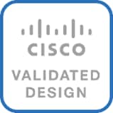
FlexPod is a best practice datacenter architecture that includes the following components:
● Cisco Unified Computing System
● Cisco Nexus switches
● Cisco MDS switches (not included in this design)
● NetApp AFF systems
Figure 1. FlexPod Component Families
These components are connected and configured according to the best practices of both Cisco and NetApp to provide an ideal platform for running a variety of enterprise workloads with confidence. FlexPod can scale up for greater performance and capacity (adding compute, network, or storage resources individually as needed), or it can scale out for environments that require multiple consistent deployments (such as rolling out of additional FlexPod stacks). The reference architecture covered in this document leverages multiple Cisco Nexus 9000 series switches, deployed as a unified VXLAN BGP EVPN network fabric to serve a single data center site. The fabric provides infrastructure connectivity for compute data and storage traffic as both NFS and iSCSI, and for the enterprise workloads deployed on the FlexPod infrastructure.
One of the key benefits of FlexPod is its ability to maintain consistency during scale. Each of the component families shown (Cisco UCS, Cisco Nexus, and NetApp AFF) offers platform and resource options to scale the infrastructure up or down, while supporting the same features and functionality that are required under the configuration and connectivity best practices of FlexPod.
Cisco Unified Computing System
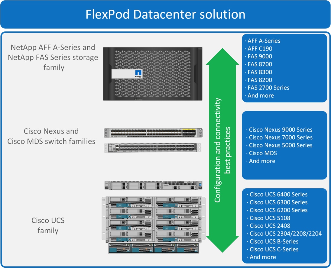
Cisco UCS B200 M5 Blade Servers
The Cisco UCS B200 M5 server shown in Figure 2, is a half-width blade upgrade from the Cisco UCS B200 M4.
Figure 2. Cisco UCS B200 M5 Blade Server
It features:
● 2nd Gen Intel® Xeon® Scalable and Intel® Xeon® Scalable processors with up to 28 cores per socket
● Up to two GPUs
● Two Small-Form-Factor (SFF) drive slots
● Up to two Secure Digital (SD) cards or M.2 SATA drives
● Up to 80 Gbps of I/O throughput with Cisco UCS 6454 FI
For more information about the Cisco UCS B200 M5 Blade Servers, see: https://www.cisco.com/c/en/us/products/collateral/servers-unified-computing/ucs-b-series-blade-servers/datasheet-c78-739296.html.
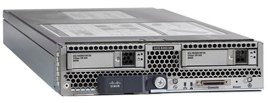
Cisco UCS C220 M5 Rack Servers
The Cisco UCS C220 M5 rack server shown in Figure 3, is a high-density 2-socket rack server that is an upgrade from the Cisco UCS C220 M4.
Figure 3. Cisco UCS C220 M5 Rack Server
It features:
● 2nd Gen Intel® Xeon® Scalable and Intel® Xeon® Scalable processors, 2-socket
● Up to 24 DDR4 DIMMs for improved performance with up to 12 DIMM slots ready for Intel Optane™ DC Persistent Memory
● Up to 10 Small-Form-Factor (SFF) 2.5-inch drives or 4 Large-Form-Factor (LFF) 3.5-inch drives (77 TB storage capacity with all NVMe PCIe SSDs)
● Support for 12-Gbps SAS modular RAID controller in a dedicated slot, leaving the remaining PCIe Generation 3.0 slots available for other expansion cards
● Modular LAN-On-Motherboard (mLOM) slot that can be used to install a Cisco UCS Virtual Interface Card (VIC) without consuming a PCIe slot
● Dual embedded Intel x550 10GBASE-T LAN-On-Motherboard (LOM) ports
● Up to 100 Gbps of I/O throughput with Cisco UCS 6454 FI
For more information about the Cisco UCS B200 M5 Blade Servers, see: https://www.cisco.com/c/en/us/products/collateral/servers-unified-computing/ucs-c-series-rack-servers/datasheet-c78-739281.html.
Cisco UCS 6400 Series Fabric Interconnects
The Cisco UCS Fabric Interconnects provide a single point for connectivity and management for the entire Cisco Unified Computing System. Typically deployed as an active-active pair, the system’s fabric interconnects integrate all components into a single, highly available management domain controlled by Cisco UCS Manager. The fabric interconnects manage all I/O efficiently and securely at a single point, resulting in deterministic I/O latency regardless of a server or virtual machine’s topological location in the system.
The Cisco UCS Fabric Interconnect provides both network connectivity and management capabilities for Cisco Unified Computing System. IOM modules in the blade chassis support power supply, along with fan and blade management. They also support port channeling and, thus, better use of bandwidth. The IOMs support virtualization-aware networking in conjunction with the Fabric Interconnects and Cisco Virtual Interface Cards (VIC).
The Cisco UCS 6400 Series Fabric Interconnect is a core part of Cisco Unified Computing System, providing both network connectivity and management capabilities for the system. The Cisco UCS 6400 Series offers line-rate, low-latency, lossless 10/25/40/100 Gigabit Ethernet, Fibre Channel over Ethernet (FCoE), and 32 Gigabit Fibre Channel functions.
The Cisco UCS 6454 54-Port Fabric Interconnect is a One-Rack-Unit (1RU) 10/25/40/100 Gigabit Ethernet, FCoE and Fibre Channel switch offering up to 3.82 Tbps throughput and up to 54 ports. The switch has 28 10/25-Gbps Ethernet ports, 4 1/10/25-Gbps Ethernet ports, 6 40/100-Gbps Ethernet uplink ports and 16 unified ports that can support 10/25-Gbps Ethernet ports or 8/16/32-Gbps Fibre Channel ports. All Ethernet ports are capable of supporting FCoE.
The Cisco UCS 64108 Fabric Interconnect (FI) is a 2-RU top-of-rack switch that mounts in a standard 19-inch rack such as the Cisco R Series rack. The 64108 is a 10/25/40/100 Gigabit Ethernet, FCoE and Fiber Channel switch offering up to 7.42 Tbps throughput and up to 108 ports. The switch has 16 unified ports (port numbers 1-16) that can support 10/25-Gbps SFP28 Ethernet ports or 8/16/32-Gbps Fibre Channel ports, 72 10/25-Gbps Ethernet SFP28 ports (port numbers 17-88), 8 1/10/25-Gbps Ethernet SFP28 ports (port numbers 89-96), and 12 40/100-Gbps Ethernet QSFP28 uplink ports (port numbers 97-108). All Ethernet ports are capable of supporting FCoE. The Cisco UCS 64108 FI is supported in the FlexPod solution but was not validated in this project.
For more information on the Cisco UCS 6400 Series Fabric Interconnects, see the Cisco UCS 6400 Series Fabric Interconnects Data Sheet.
Cisco UCS 2408 Fabric Extender
The Cisco UCS 2408 connects the I/O fabric between the Cisco UCS 6454 Fabric Interconnect and the Cisco UCS 5100 Series Blade Server Chassis, enabling a lossless and deterministic converged fabric to connect all blades and chassis together. Because the fabric extender is similar to a distributed line card, it does not perform any switching and is managed as an extension of the fabric interconnects. This approach removes switching from the chassis, reducing overall infrastructure complexity, and enabling Cisco UCS to scale to many chassis without multiplying the number of switches needed, reducing TCO, and allowing all chassis to be managed as a single, highly available management domain.
The Cisco UCS 2408 Fabric Extender has eight 25-Gigabit Ethernet, FCoE-capable, Small Form-Factor Pluggable (SFP28) ports that connect the blade chassis to the fabric interconnect. Each Cisco UCS 2408 provides 10-Gigabit Ethernet ports connected through the midplane to each half-width slot in the chassis, giving it a total 32 10G interfaces to UCS blades. Typically configured in pairs for redundancy, two fabric extenders provide up to 400 Gbps of I/O from FI 6400's to 5108 chassis.
Cisco UCS 1400 Series Virtual Interface Cards (VICs)
Cisco VICs support Cisco SingleConnect technology, which provides an easy, intelligent, and efficient way to connect and manage computing in your data center. Cisco SingleConnect unifies LAN, SAN, and systems management into one simplified link for rack servers and blade servers. This technology reduces the number of network adapters, cables, and switches needed and radically simplifies the network, reducing complexity. Cisco VICs can support 256 Express (PCIe) virtual devices, either virtual Network Interface Cards (vNICs) or virtual Host Bus Adapters (vHBAs), with a high rate of I/O Operations Per Second (IOPS), support for lossless Ethernet, and 10/25/40/100-Gbps connection to servers. The PCIe Generation 3 x16 interface helps ensure optimal bandwidth to the host for network-intensive applications, with a redundant path to the fabric interconnect. Cisco VICs support NIC teaming with fabric failover for increased reliability and availability. In addition, it provides a policy-based, stateless, agile server infrastructure for your data center.
The Cisco VIC 1400 series is designed exclusively for the M5 generation of Cisco UCS B-Series Blade Servers and Cisco UCS C-Series Rack Servers. The adapters are capable of supporting 10/25/40/100-Gigabit Ethernet and Fibre Channel over Ethernet (FCoE). It incorporates Cisco’s next-generation Converged Network Adapter (CNA) technology and offers a comprehensive feature set, providing investment protection for future feature software releases.
Cisco Unified Computing System is revolutionizing the way servers are managed in the datacenter. The following are the unique differentiators of Cisco Unified Computing System and Cisco UCS Manager.
● Embedded Management — In Cisco UCS, the servers are managed by the embedded firmware in the Fabric Interconnects, eliminating need for any external physical or virtual devices to manage the servers.
● Unified Fabric — In Cisco UCS, from blade server chassis or rack servers to FI, there is a single Ethernet cable used for LAN, SAN, and management traffic. This converged I/O results in reduced cables, SFPs and adapters – reducing capital and operational expenses of the overall solution.
● Auto Discovery — By simply inserting the blade server in the chassis or connecting the rack server to the fabric interconnect, discovery and inventory of compute resources occurs automatically without any management intervention. The combination of unified fabric and auto-discovery enables the wire-once architecture of Cisco UCS, where compute capability of Cisco UCS can be extended easily while keeping the existing external connectivity to LAN, SAN, and management networks.
● Policy Based Resource Classification — Once a compute resource is discovered by Cisco UCS Manager, it can be automatically classified to a given resource pool based on policies defined. This capability is useful in multi-tenant cloud computing. This CVD showcases the policy-based resource classification of Cisco UCS Manager.
● Combined Rack and Blade Server Management — Cisco UCS Manager can manage Cisco UCS B-series blade servers and Cisco UCS C-series rack servers under the same Cisco UCS domain. This feature, along with stateless computing makes compute resources truly hardware form factor agnostic.
● Model based Management Architecture — The Cisco UCS Manager architecture and management database is model based, and data driven. An open XML API is provided to operate on the management model. This enables easy and scalable integration of Cisco UCS Manager with other management systems.
● Policies, Pools, Templates — The management approach in Cisco UCS Manager is based on defining policies, pools, and templates, instead of cluttered configuration, which enables a simple, loosely coupled, data driven approach in managing compute, network, and storage resources.
● Loose Referential Integrity — In Cisco UCS Manager, a service profile, port profile or policies can refer to other policies or logical resources with loose referential integrity. A referred policy cannot exist at the time of authoring the referring policy or a referred policy can be deleted even though other policies are referring to it. This provides different subject matter experts to work independently from each-other. This provides great flexibility where different experts from different domains, such as network, storage, security, server, and virtualization work together to accomplish a complex task.
● Policy Resolution — In Cisco UCS Manager, a tree structure of organizational unit hierarchy can be created that mimics the real-life tenants and/or organization relationships. Various policies, pools and templates can be defined at different levels of organization hierarchy. A policy referring to another policy by name is resolved in the organizational hierarchy with closest policy match. If no policy with specific name is found in the hierarchy of the root organization, then the special policy named “default” is searched. This policy resolution practice enables automation friendly management APIs and provides great flexibility to owners of different organizations.
● Service Profiles and Stateless Computing — A service profile is a logical representation of a server, carrying its various identities and policies. This logical server can be assigned to any physical compute resource as far as it meets the resource requirements. Stateless computing enables procurement of a server within minutes, which used to take days in legacy server management systems.
● Built-in Multi-Tenancy Support — The combination of policies, pools and templates, loose referential integrity, policy resolution in the organizational hierarchy and a service profiles-based approach to compute resources makes Cisco UCS Manager inherently friendly to multi-tenant environments typically observed in private and public clouds.
● Extended Memory — The enterprise-class Cisco UCS B200 M5 blade server extends the capabilities of Cisco’s Unified Computing System portfolio in a half-width blade form factor. The Cisco UCS B200 M5 harnesses the power of the latest Intel® Xeon® Scalable Series processor family CPUs with up to 3 TB of RAM (using 128 GB DIMMs) – allowing huge VM to physical server ratios required in many deployments or allowing large memory operations required by certain architectures like big data.
● Simplified QoS — Even though Fibre Channel and Ethernet are converged in the Cisco UCS fabric, built-in support for QoS and lossless Ethernet makes it seamless. Network Quality of Service (QoS) is simplified in Cisco UCS Manager by representing all system classes in one GUI panel.
NetApp AFF A-Series Storage
With the new NetApp® AFF A-Series controller lineup, NetApp provides industry leading performance while continuing to provide a full suite of enterprise-grade data management and data protection features. NetApp All Flash FAS (AFF) systems address enterprise storage requirements with high performance, superior flexibility, and best-in-class data management. Built on NetApp ONTAP data management software, AFF systems speed up business without compromising on the efficiency, reliability, or flexibility of IT operations. As an enterprise-grade all-flash array, AFF accelerates, manages, and protects business-critical data and enables an easy and risk-free transition to flash for your data center. Additionally, more and more organizations are adopting a “cloud first” strategy, driving the need for enterprise-grade data services for a shared environment across on-premises data centers and the cloud. As a result, modern all-flash arrays must provide robust data services, integrated data protection, seamless scalability, and new levels of performance— plus deep application and cloud integration. These new workloads demand performance that first generation flash systems cannot deliver.
For more information about the NetApp AFF A-series controllers, see the AFF product page: https://www.netapp.com/us/products/storage-systems/all-flash-array/aff-a-series.aspx.
You can view or download more technical specifications of the AFF A-series controllers here: https://www.netapp.com/us/media/ds-3582.pdf
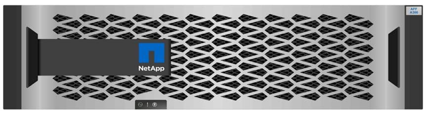
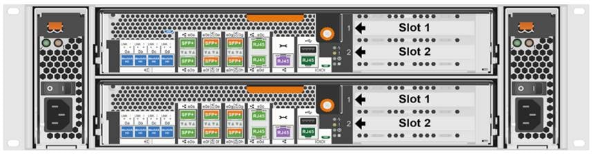
This architecture uses NetApp AFF A300 series unified scale-out storage system. This controller provides the high-performance benefits of 40GbE and all flash SSDs and occupies only 3U of rack space. Combined with a disk shelf containing 3.8TB disks, this solution provides ample horsepower and over 90TB of raw capacity while taking up only 5U of valuable rack space. The AFF A300 features a multiprocessor Intel chipset and leverages high-performance memory modules, NVRAM to accelerate and optimize writes, and an I/O-tuned PCIe gen3 architecture that maximizes application throughput. The AFF A300 series comes with integrated unified target adapter (UTA2) ports that support 16Gb Fibre Channel, 10GBE, and FCoE. In addition, 40GbE and 32 Gb FC add-on cards are available.
NetApp also expanded its services to improve efficiency and performance while protecting against disruption and data loss.
NetApp’s expanded services portfolio now includes:
● SupportEdge Prestige offers a high-touch, concierge level of technical support that resolves issues faster through priority call routing. Customers are assigned a designated team of NetApp experts and receive specialized reporting, tools, and storage environment health assessments.
● Tiered Deployment Service accelerates time to value for new NetApp technology and reduces the risk of improper installation or misconfiguration. Three new high-quality options include Basic, Standard, and Advanced Deployment, each aligned to customer business objectives.
● Managed Upgrade Service is a remotely delivered service that reduces security risks by ensuring NetApp software is always up to date with all security patches and firmware upgrades.
Figure 4. NetApp AFF A300
NetApp ONTAP® 9.7 is the data management software that is used with the NetApp AFF A300 all-flash storage system in the solution design. ONTAP software offers secure unified storage for applications that read and write data over block or file-access protocol storage configurations. These storage configurations range from high-speed flash to lower-priced spinning media or cloud-based object storage.
ONTAP implementations can run on NetApp engineered FAS or AFF series arrays. They can run on commodity hardware (NetApp ONTAP Select), and in private, public, or hybrid clouds (NetApp Private Storage and NetApp Cloud Volumes ONTAP). Specialized implementations offer best-in-class converged infrastructure, featured here as part of the FlexPod® Datacenter solution or with access to third-party storage arrays (NetApp FlexArray® virtualization).
Together these implementations form the basic framework of the NetApp Data Fabric, with a common software-defined approach to data management, and fast efficient replication across systems. FlexPod and ONTAP architectures can serve as the foundation for both hybrid cloud and private cloud designs.
The following sections provide an overview of how ONTAP 9.7 is an industry-leading data management software architected on the principles of software defined storage.
Read more about all the capabilities of ONTAP data management software here: https://www.netapp.com/us/products/data-management-software/ontap.aspx
New Controller Support
ONTAP 9.7 introduces support for the new AFF and FAS controller models including:
● AFF A300
● FAS8300
● FAS8700
NetApp Storage Virtual Machine
A NetApp ONTAP cluster serves data through at least one, and possibly multiple, storage virtual machines (SVMs). An SVM is a logical abstraction that represents the set of physical resources of the cluster. Data volumes and network LIFs are created and assigned to an SVM and can reside on any node in the cluster to which that SVM has access. An SVM can own resources on multiple nodes concurrently, and those resources can be moved non-disruptively from one node in the storage cluster to another. For example, a NetApp FlexVol® flexible volume can be non-disruptively moved to a new node and aggregate, or a data LIF can be transparently reassigned to a different physical network port. The SVM abstracts the cluster hardware, and therefore it is not tied to any specific physical hardware.
An SVM can support multiple data protocols concurrently. Volumes within the SVM can be joined to form a single NAS namespace. The namespace makes all of the SVM's data available through a single share or mount point to NFS and CIFS clients. SVMs also support block-based protocols, and LUNs can be created and exported by using iSCSI, FC, and FCoE. Any or all of these data protocols can be used within a given SVM. Storage administrators and management roles can be associated with an SVM, offering higher security and access control. This security is important in environments that have more than one SVM and when the storage is configured to provide services to different groups or sets of workloads. In addition, you can configure external key management for a named SVM in the cluster. This is a best practice for multitenant environments in which each tenant uses a different SVM (or set of SVMs) to serve data.
Storage Efficiencies
Storage efficiency is a primary architectural design point of ONTAP data management software. A wide array of features enables you to store more data that uses less space. In addition to deduplication and compression, you can store your data more efficiently by using features such as unified storage, multitenancy, thin provisioning, and by using NetApp Snapshot™ technology.
Starting with ONTAP 9, NetApp guarantees that the use of NetApp storage efficiency technologies on AFF systems reduces the total logical capacity used to store customer data up to a data reduction ratio of 7:1, based on the workload. This space reduction is enabled by a combination of several different technologies, including deduplication, compression, and compaction.
Compaction, which was introduced in ONTAP 9, is the latest patented storage efficiency technology released by NetApp. In the NetApp WAFL® file system, all I/O takes up 4KB of space, even if it does not actually require 4KB of data. Compaction combines multiple blocks that are not using their full 4KB of space together into one block. This single block can be more efficiently stored on the disk to save space. These storage efficiencies improve the ability of ONTAP to store more data in less space, reducing storage costs and maximizing the effective capacity of your storage system.
FabricPool
FabricPool is a hybrid storage solution with ONTAP 9 that uses an all-flash (SSD) aggregate as a performance tier and an object store in a public cloud service as a cloud tier. This configuration enables policy-based data movement, depending on whether or not data is frequently accessed. FabricPool is supported in ONTAP for both AFF and all-SSD aggregates on FAS platforms. Data processing is performed at the block level, with frequently accessed data blocks in the all-flash performance tier tagged as hot and infrequently accessed blocks tagged as cold.
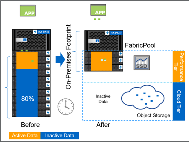
Using FabricPool helps to reduce storage costs without compromising performance, efficiency, security, or protection. FabricPool is transparent to enterprise applications and capitalizes on cloud efficiencies by lowering storage TCO without having to rearchitect the application infrastructure.
Encryption
Data security remains an important consideration for customers purchasing storage systems. Before ONTAP 9, NetApp supported full disk encryption in storage clusters. However, in ONTAP 9, the encryption capabilities of ONTAP are extended by adding an Onboard Key Manager (OKM). The OKM generates and stores keys for each of the drives in ONTAP, enabling ONTAP to provide all functionality required for encryption out of the box. Through this functionality, known as NetApp Storage Encryption (NSE), sensitive data stored on disk is secure and can only be accessed by ONTAP.
NetApp has extended the encryption capabilities further with NetApp Volume Encryption (NVE), a software-based mechanism for encrypting data. It allows a user to encrypt data at the volume level instead of requiring encryption of all data in the cluster, providing more flexibility and granularity to ONTAP administrators. This encryption extends to Snapshot copies and NetApp FlexClone volumes that are created in the cluster. One benefit of NVE is that it runs after the implementation of the storage efficiency features, and, therefore, it does not interfere with the ability of ONTAP to create space savings. Continuing in ONTAP 9.7 is the ability to preserve NVE in NetApp Cloud Volumes. NVE unifies the data encryption capabilities available on-premises and extends them into the cloud. NVE in ONTAP 9.7 is also FIPS 140-2 compliant. This compliance helps businesses adhere to federal regulatory guidelines for data at rest in the cloud.
ONTAP 9.7 introduces data-at-rest encryption as the default. Data-at-rest encryption is now enabled when an external or onboard key manager (OKM) is configured on the cluster or SVM. This means that all new aggregates created will have NetApp Aggregate Encryption (NAE) enabled and any volumes created in non-encrypted aggregates will have NetApp Volume Encryption (NVE) enabled by default. Aggregate level deduplication is not sacrificed, as keys are assigned to the containing aggregate during volume creation, thereby extending the native storage efficiency features of ONTAP without sacrificing security.
For more information about encryption in ONTAP, see the NetApp Power Encryption Guide in the NetApp ONTAP 9 Documentation Center.
FlexClone
NetApp FlexClone technology enables instantaneous point-in-time copies of a FlexVol volume without consuming any additional storage until the cloned data changes from the original. FlexClone volumes add extra agility and efficiency to storage operations. They take only a few seconds to create and do not interrupt access to the parent FlexVol volume. FlexClone volumes use space efficiently, applying the ONTAP architecture to store only data that changes between the parent and clone. FlexClone volumes are suitable for testing or development environments, or any environment where progress is made by locking-in incremental improvements. FlexClone volumes also benefit any business process where you must distribute data in a changeable form without endangering the integrity of the original.
SnapMirror (Data Replication)
NetApp SnapMirror® is an asynchronous replication technology for data replication across different sites, within the same data center, on-premises datacenter to cloud, or cloud to on-premises datacenter. SnapMirror Synchronous (SM-S) offers volume granular, zero data loss protection. It extends traditional SnapMirror volume replication to synchronous mode meeting zero recovery point objective (RPO) disaster recovery and compliance objectives. ONTAP 9.7 extends support for SnapMirror Synchronous to application policy-based replication providing a simple and familiar configuration interface that is managed with the same tools as traditional SnapMirror. This includes ONTAP CLI, NetApp ONTAP System Manager, NetApp Active IQ Unified Manager, and NetApp Manageability SDK.
The 9.7.1 release of the virtual appliance for Virtual Storage Console (VSC), VASA Provider, and Storage Replication Adapter (SRA) provides the combined features of VSC, VASA Provider, and SRA in a single deployment.
NetApp Virtual Storage Console (VSC) for VMware vSphere is a vSphere client plug-in that provides end-to-end lifecycle management for virtual machines (VMs) in VMware environments that use NetApp AFF and FAS storage systems. VSC provides visibility into the NetApp storage environment from within the vSphere web client. VMware administrators can easily perform tasks that improve both server and storage efficiency while still using role-based access control to define the operations that administrators can perform.
The 9.7.1 release of the virtual appliance for VSC, VASA Provider, and SRA includes enhanced REST APIs that will provide vVols metrics for SAN storage systems using ONTAP 9.7 and later. So, OnCommand API Services is no longer required to get metrics for ONTAP systems 9.7 and later. These REST APIs currently only support metrics for SAN datastores.
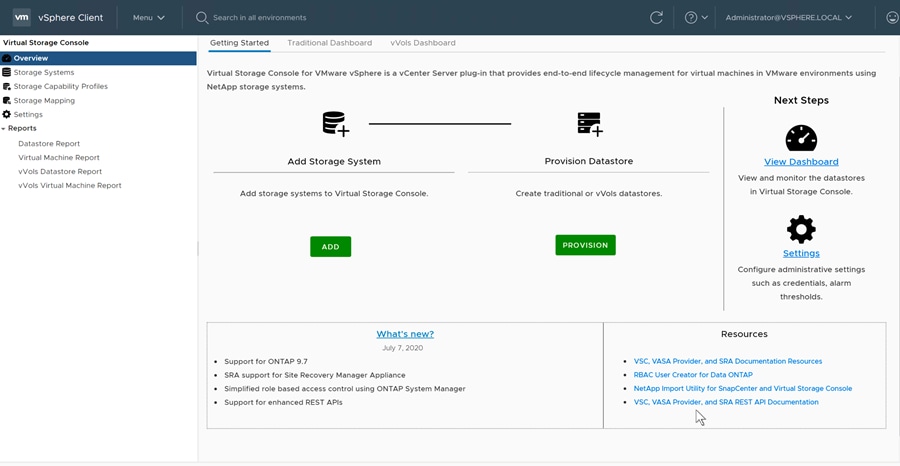
VSC applies NetApp technologies to deliver comprehensive, centralized management of ONTAP® storage operations in both SAN and NAS-based VMware infrastructures. These operations include discovery, health, and capacity monitoring, and datastore provisioning. VSC delivers tighter integration between storage and virtual environments and greatly simplifies virtualized storage management. After it is installed, VSC provides a view of the storage environment from a VMware administrator’s perspective and optimizes storage and host configurations for use with NetApp AFF and FAS storage systems.
![]() VSC 9.7.1 supports Provisioning of vVols over FC, ISCSI and NFS datastores for vSphere 7.
VSC 9.7.1 supports Provisioning of vVols over FC, ISCSI and NFS datastores for vSphere 7.
Active IQ Unified Manager 9.7P1
NetApp® Active IQ® Unified Manager is a comprehensive monitoring and proactive management tool for NetApp ONTAP® systems to help manage the availability, capacity, protection, and performance risks of your storage systems and virtual infrastructure. You can deploy Unified Manager on a Linux server, on a Windows server, or as a virtual appliance on a VMware host.
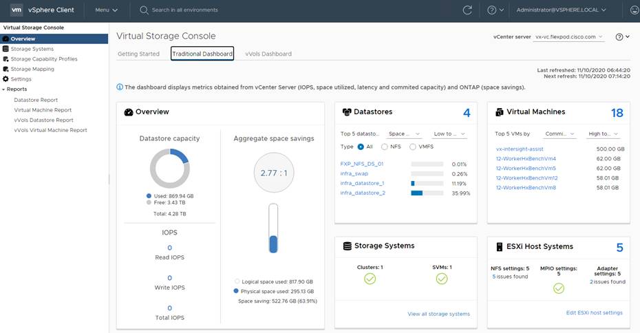
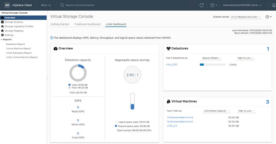
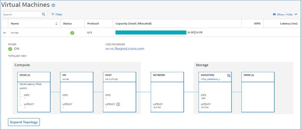
Active IQ Unified Manager enables monitoring your ONTAP storage clusters, VMware vCenter server and virtual machines from a single redesigned, intuitive interface that delivers intelligence from community wisdom and AI analytics. It provides comprehensive operational, performance and proactive insights into the storage environment and the virtual machines running on it. When an issue occurs on the storage or virtual infrastructure, Unified Manager can notify you about the details of the issue to help with identifying root cause. The virtual machine dashboard gives you a view into the performance statistics for the VM so that you can investigate the entire I/O path from the vSphere host down through the network and finally to the storage. Some events also provide remedial actions which can be taken to rectify the issue. You can configure custom alerts for events so that when issues occur, you are notified through email, and SNMP traps.
Active IQ Unified Manager enables management of storage objects in your environment by associating them with annotations. You can create custom annotations and dynamically associate clusters, storage virtual machines (SVMs), and volumes with the annotations through rules.
Active IQ Unified Manager also enables reporting different views of your network, providing actionable intelligence on capacity, health, performance, and data protection. You can customize your views by showing and hiding columns, rearranging columns, filtering data, sorting data, and searching the results. You can save custom views for reuse, download them as reports, and schedule them as recurring reports to distribute through email. Active IQ Unified Manager enables planning for the storage requirements of your users by forecasting capacity and usage trends to proactively act before issues arise preventing reactive short-term decisions which often lead additional problems in the long-term.
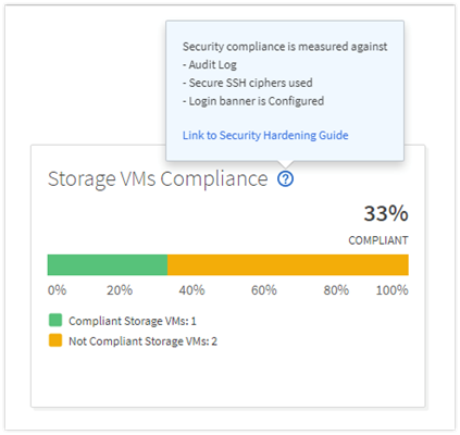
Active IQ Unified Manager 9.7 introduces a new security risk panel that provide an overview of the security posture of the storage system and provides corrective actions to harden ONTAP. Active IQ Unified Manager uses rules based on the recommendations made in the Security Hardening Guide for NetApp ONTAP 9 (TR-4569) to evaluate the cluster and SVM configuration. Each recommendation is assigned a value and used to provide an overall compliance score for the ONTAP environment.
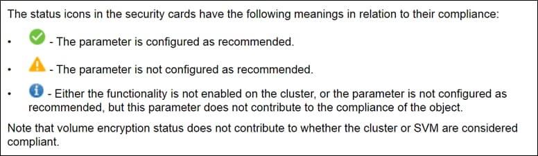
The compliance score is calculated by auditing certain recommendations made in the Security Hardening Guide and whether the remediation for those risks have been completed. The recommendations included are general in nature and can be applied to most ONTAP environments regardless of workload. Certain criteria are not counted against the compliance score because those configurations cannot be generally applied to all storage environments. Volume encryption would be one an example of this.
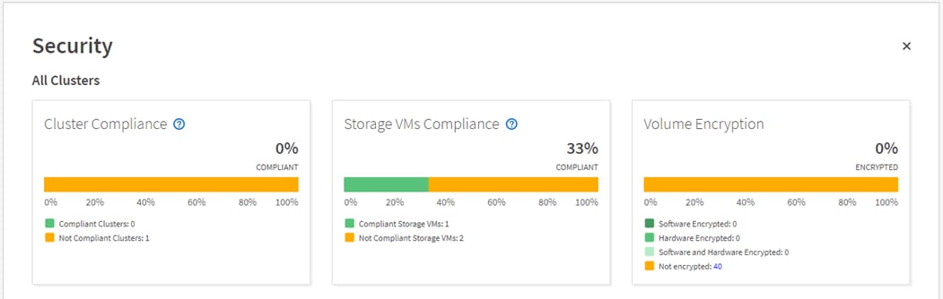
A list of recommendations being evaluated for compliance can be seen by selecting the blue question mark in each security card which also contains a link to the Security Hardening Guide for NetApp ONTAP 9.
For more information on Active IQ Unified Manager refer to the Active IQ Unified Manager Documentation Resources page complete with a video overview and other product documentation.
NetApp Active IQ is a cloud service that provides proactive care and optimization of your NetApp environment, leading to reduced risk and higher availability. Active IQ leverages community wisdom and AIOps artificial intelligence to provide proactive recommendations and risk identification. The latest release of Active IQ offers an enhanced user interface and a personalized experience with Active IQ Digital Advisor dashboards. It allows smooth and seamless navigation, with its intuitiveness throughout different dashboards, widgets, and screens. It provides insights that help you detect and validate important relationships and meaningful differences based on the data that is presented by different dashboards.
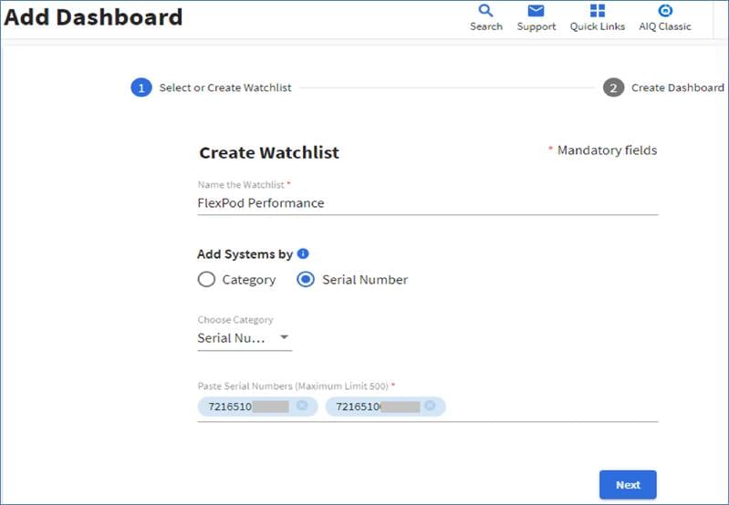
Watchlists are a way to organize a group of systems inside Active IQ Digital Advisor and create custom dashboards based on the system grouping. Watchlists provide quick access to only the group of storage systems you want, without having to sort or filter those you don’t want.
The Wellness score on the dashboard provides a quick at-a-glance summary on the health of the installed systems based on the number of high risks and expired support contracts. Detailed information about the status of your storage system are sorted into the following widgets:
● Performance and Efficiency
● Availability and Protection
● Capacity
● Configuration
● Security
● Renewals
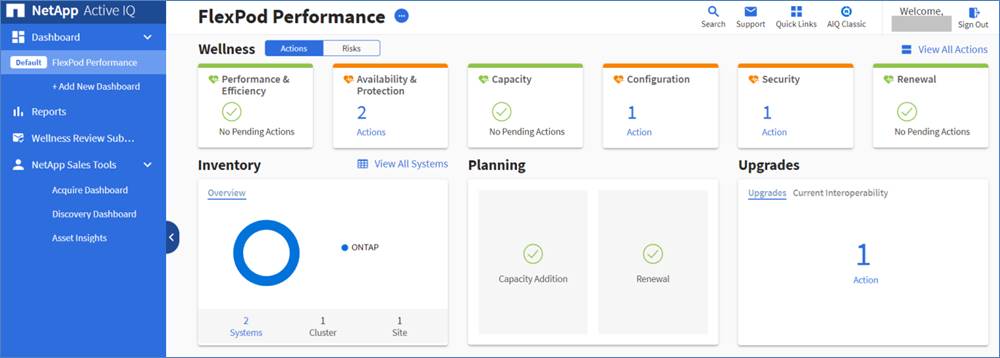
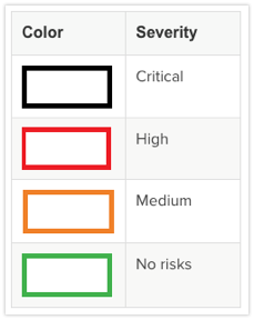
The intuitive interface allows you to switch between the Actions and Risks tab to view how the findings are broken down by category, or each unique risk. Color-coding the identified risks into four levels; Critical, High, Medium and No risks, further helps to quickly identify issues that need immediate attention.
Links to NetApp Bugs Online or NetApp MySupport knowledge base articles are incorporated in the corrective actions so that you can obtain further information about the issue and how to correct it before it becomes a problem in the environment.
Active IQ also integrates with the on-premises installation of Active IQ Unified Manager to correct certain issues identified in the Active IQ portal. These risks are identified with the green wrench symbol in the Risks tab inside Active IQ. Clicking the Fix It button will launch the installation of Active IQ Unified Manager 9.7 to proceed with correcting the issue. If no installation of Active IQ Unified Manager 9.7 exists, the option to install or upgrade an existing version of Active IQ Unified Manager will be presented for future risk mitigation.
Data Center Fabric – VXLAN MP-BGP EVPN
Modern data centers have evolved from traditional Layer 2 networks based on VLANs and spanning tree and hierarchical 3-tier designs, to modern CLOS-based designs with Virtual Extensible LAN (VXLAN) as the overlay technology. VXLAN is an industry standard that supports the needs of modern data centers by creating a flexible network (overlay) across a shared IP network infrastructure (underlay). It is the most commonly used overlay technology in today’s data centers. VXLAN brings scalability and extensibility to VLAN networks while also solving specific data center challenges such as dynamic workload placement, endpoint mobility, Layer 2 scalability and Layer 2 extension across Layer 3 network boundaries. VXLAN with MP-BGP also addresses the needs of multi-tenant data centers without compromising resiliency, security, and performance. VXLAN is an IETF standard, making it interoperable in a multi-vendor data center environment with Cisco and non-Cisco switches.
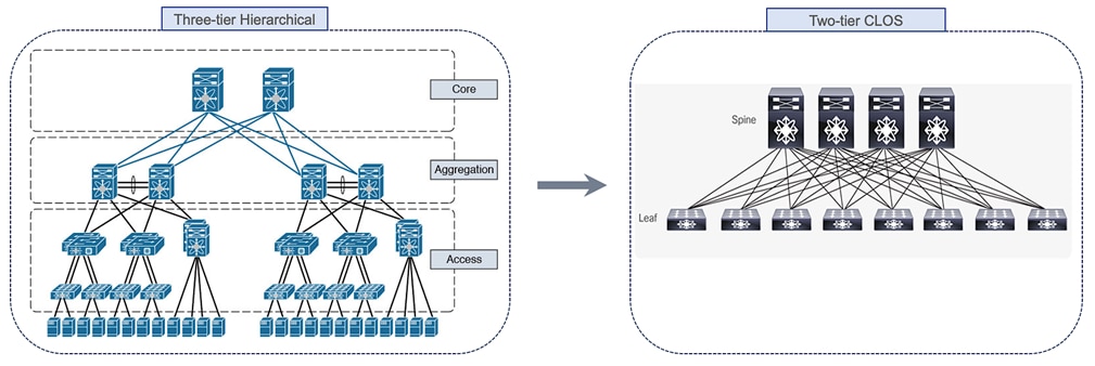
Modern data center applications have also caused a shift in data center traffic patterns, resulting in a high-percentage of east-to-west traffic. Modern applications are often deployed in a distributed fashion, with both the applications and the technologies that support them such as virtualization, containers and clustering requiring Layer 2 adjacency between components that are distributed across the data center network. The increase in east-west traffic also revealed some challenges in a traditional three-tier design, including bandwidth bottlenecks and variations in latency that varied with the path of the traffic. These shifts in traffic pattern and requirements resulted in an evolution of the underlying data center network to a more efficient, CLOS-based, two-tier spine and leaf architecture as shown in Figure 5. CLOS-based architectures deliver predictable low-latency, high-bandwidth with horizontal scalability.
Figure 5. Data Center Network Architecture - Evolution
Another shift in modern data centers is the user demand for agility and simplicity so that they can quickly deploy the infrastructure necessary to develop, deploy and scale their applications, where the workloads are distributed across different physical, virtual and cloud environments. They also want the flexibility to move these workloads between locations and environments without compromising on their other requirements. This has driven Cisco and other vendors to develop programmable fabrics with open APIs, Software-Defined Networking (SDN) and similar solutions to address this need.
VXLAN is an overlay technology that provides a scalable and more efficient network architecture for deploying applications and services in a data center by virtualizing the underlying shared network infrastructure to support Layer 2 extension and Layer 3 forwarding of edge networks.
Some additional benefits of a VXLAN network fabric in a data center are:
● Flexible placement of tenant workloads throughout the data center. VXLAN provides a solution to extend Layer 2 segments over the underlying shared network infrastructure so that tenant workload can be placed across physical segments anywhere in the data center.
● Layer 2 adjacency for clustering services and application workloads in the data center. Layer 2 extension enabled by VXLAN also enables applications and services such VMware vMotion to have Layer 2 adjacency across the across the shared network infrastructure. The Layer 2 extension includes MAC-address mobility which are critical for Layer 2 clustering services and for supporting live-migration of virtual machines.
● Multi-tenancy and Segmentation: VXLAN supports the flexible placement of multi-tenant segments and workloads throughout the data center. VXLAN maps each edge network to a virtual or an overlay network that is tunneled across a shared network infrastructure. Each virtual network uses a dedicated Network Identification (NID) which segments that traffic across a shared network infrastructure. This also enables data-plane support for multi-tenant Layer 3 networks across the shared network infrastructure.
● Higher scalability to address more Layer 2 segments. VXLAN uses a 24-bit segment ID which enables up to 16 million VXLAN segments to coexist in the same shared network infrastructure.
● Increased utilization of available network paths in the underlying infrastructure. VXLAN packets are forwarded through the underlying network based on its Layer 3 header and can take complete advantage of Layer 3 routing, equal-cost multipath (ECMP) routing, and link aggregation protocols to use all available paths.
On Cisco Nexus switches, the VXLAN encapsulation/decapsulation is done in hardware unlike software-based implementations. This ensures line-rate performance regardless of packet sizes which is critical for application performance across a VXLAN fabric.
Multi-Protocol Border Gateway Protocol (MP-BGP)
Ethernet switched networks use a data-plane mechanism of flood-and-learn to learn endpoint locations and addresses, and to ensure reachability to unknown or yet-to-be learned endpoints. The data-plane flooding mechanism can also be used when these network segments are interconnected by a VXLAN fabric. IETF RFC 7348 is a data-plane based VXLAN standard that uses a multicast-based flood-and-learn mechanism for address-learning. However, for a more efficient and scalable solution, IETF has also standardized a control-plane protocol, MP-BGP (RFC 7342) for distributing end-host reachability information (or address learning) in VXLAN networks. MP-BGP is a prevalent, well-established, and proven network routing protocol that has been used for decades by large provider networks, including Internet Service Providers for managing and distributing Internet routing tables. MP-BGP also provides administrators with greater flexibility and control through policies that can be applied to attributes inherent in the protocol. Another advantage of MP-BGP is that it provides a unified control plane for distributing Layer 2 and Layer 3 reachability information. MP-BGP can be used to advertise MAC addresses, IP addresses and IP prefixes - all of which are needed to support integrated routing and bridging in VXLAN overlay networks.
Ethernet Virtual Private Network (EVPN)
MP-BGP EVPN is an extension to MP-BGP that provides multi-tenancy using a new address-family and VPN constructs such as Virtual Routing Forwarding (VRF) that have long been used in MPLS VPNs. The use of MP-BGP EVPN as a control protocol for VXLAN is standardized by IETF RFC 7342. With MP-BGP EVPN, multiple tenants can co-exist on the same shared network while maintaining tenant separation through separate VPNs in the overlay network.
In the data-plane, each edge network is mapped to a VXLAN Network Identifier (VNID) that identifies the segment and traffic with it as it traverses the shared IP transport network. Layer 3 segmentation is similarly achieved by using a Layer 3 VNID for each VRF where each VRF represents a tenant. Tenant isolation is achieved by enforcing routing and forwarding isolation between tenants using VRFs and Layer 3 VNIDs. Layer 2 segmentation is similarly achieved by enforcing VNID boundaries by preventing endpoints in one segment from communicating with other segments.
In the control-plane, MP-BGP supports multi-tenancy through the use of a new Layer 2 VPN or EVPN address-family. MP-BGP can advertise both Layer-2 and Layer-3 reachability information using the EVPN address-family. MP-BGP EVPN is similar to MPLS-based Layer 3 VPNs (L3VPNs) and use the same concepts to provide tenant separation in the control plane. Similar to MPLS L3VPNs, a Route Distinguisher (RD) will ensure the global uniqueness of addresses belonging to different VPNs (or VRFs) when advertising them to other BGP peers and route-targets (RT) will associate the addresses to a VRF for flexible exporting and importing of routes between peers in the same VRF and across VRFs.
Built-in multitenancy support is a key advantage of MP-BGP EVPN VXLAN when compared to flood-and-learn VXLAN networks or other Layer 2 extension technologies without multitenancy capabilities. Multitenancy, coupled with scalability and flexibility, makes VXLAN MP-BGP EVPN fabrics more suitable for large data centers and cloud networks.
Cisco Data Center Network Manager (DCNM)
Cisco DCNM provides comprehensive automation and visibility for deploying, operating, and managing a data center network fabric with Cisco Nexus switches running NX-OS software. The fabrics supported by Cisco DCNM includes LAN fabrics, SAN fabrics and IP fabric for Media. Cisco DCNM can be deployed as Virtual Appliance (OVA or ISO) for LAN fabrics. The deployment offered by DCNM LAN Fabric is GUI/API based, giving options for multi-fabric and multi-site implementations, with fabric templates available for the Nexus 3K and 9K switches. With the DCNM-LAN Fabric oversight, the network configuration is easily backed up and restored as needed. Some of the key capabilities available on Cisco DCNM are:
● Dynamic, policy-based configuration for underlay, overlay, and interfaces
● Fabric Builder for a GUI-based deployment of a VXLAN Fabric with defaults that align with Cisco recommendations and best-practices
● Customizable Fabric Builder Python++ templates
● Integrated and simplified bootstrap using Power On Auto Provisioning (POAP) integrated from within Fabric Builder
● Previews of configuration are available for review before any changes are deployed
● Once deployed, continuous configuration compliance monitoring to ensure fabric consistency
● Per-switch configuration deployment history of underlay, overlay, and interface configurations
● Support for Multi-fabric and multi-site deployments
● Overlay network provisioning for leaf and borders switches, including external connectivity
● Easy Return Material Authorization (RMA) provisioning workflow
● Simplified workflow for installs and upgrades
For more information, refer to: https://www.cisco.com/c/en/us/products/collateral/cloud-systems-management/prime-data-center-network-manager/datasheet-c78-740978.html
Network Insights for Resources and Network Insights Advisor can additionally be brought in for comprehensive monitoring and analytics of the deployed fabric.
In this FlexPod design, Cisco DCNM-LAN Fabric serves as Software-Defined Networking (SDN) controller that manages, monitors, and automates the deployment of the VXLAN data center fabric. It is deployed as a virtual appliance from an OVA and manages the fabric through a web browser. Using Cisco DCNM in this design is optional but highly recommended.
Cisco Nexus family of switches provide an Ethernet switching fabric for communications between the Cisco UCS domain, the NetApp storage system, and the enterprise network. There are many factors to consider when selecting the switches for the VXLAN architecture used in this FlexPod design. Scale, performance, and functionality are all critical factors for supporting the FlexPod Virtual Server Infrastructure (VSI) and the applications hosted in the data center. This FlexPod design leverages the Cisco Nexus 9000 series switches, which deliver high performance 10/25/40/50/100GbE ports, density, low latency, and exceptional power efficiency in a broad range of compact form factors. Many of the recent single-site FlexPod designs also use the Cisco Nexus 9000 series switch due to the advanced feature set and the ability to support either the VXLAN with Multi-Protocol Border Gateway Protocol (MP-BGP) Ethernet Virtual Private Networks (EVPN) or the Application Centric Infrastructure (ACI) fabric. When leveraging VXLAN or ACI fabric mode, the Cisco Nexus 9000 series switches are deployed in a spine-leaf architecture.
For more information, refer to https://www.cisco.com/c/en/us/products/switches/nexus-9000-series-switches/index.html.
This FlexPod design deploys a single pair of Cisco Nexus 9336C-FX2 top-of-rack switches to connect to the Cisco UCS compute and NetApp storage infrastructure. The switches are part of the VXLAN fabric and deployed in standalone mode running NX-OS. The Cisco UCS Fabric Interconnects and NetApp storage systems are connected to the Cisco Nexus 9000 switches in the VXLAN fabric using virtual Port Channels (vPC).
Some of the benefits of using Cisco Nexus 9000 series switches for this design are:
● High performance and scalability with L2 and L3 support per port
● Line rate VXLAN encapsulation/decapsulation and forwarding
● Layer 2 multipathing with all paths forwarding through the Virtual port-channel (vPC) technology
● Advanced reboot capabilities include hot and cold patching
● Hot-swappable power-supply units (PSUs) and fans with N+1 redundancy
Virtual Port Channel (vPC)
As stated earlier, vPCs are used in this design for access-layer connectivity to connect Leaf switches in the VXLAN fabric to the FlexPod compute and storage infrastructure in the edge network. A virtual Port Channel allows links that are physically connected to two different Leaf switches to appear as a single Port Channel. The benefits of using a vPC are:
● Allows a single device to use a Port Channel to connect to two upstream devices, providing link and node resiliency while providing higher aggregate bandwidth
● Uses all available uplink bandwidth by eliminating blocked ports/links in Spanning Tree
● Provides a loop-free topology
● Provides fast convergence if either one of the physical links or a device fails
● Helps ensure high availability of the overall FlexPod system
Cisco Nexus 9000 Best Practices and Other Considerations
This section covers the features and best practices for the Cisco Nexus 9000 series switches that are used as Leaf switches in this design. The Leaf switches are fully configured and deployed by Cisco DCNM and implements Cisco’s best practice recommendations – by default.
Cisco Nexus 9000 Features
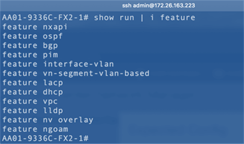
The Cisco Nexus 9000 Features enabled in this FlexPod design are shown in Figure 6. Cisco DCNM enabled these features automatically on the Cisco Nexus Leaf switches in the process of bringing up the VXLAN fabric and connecting endpoints and edge devices to it. LLDP was manually enabled on all the switches as it was required Cisco DCNM’s discovery process – this is not necessary if Power On Auto Provisioning (POAP) is used.
Figure 6. Cisco Nexus 9000 Leaf Switch Features
Virtual Port Channel Considerations
The best practices and other considerations for deploying vPCs are listed below. Cisco DCNM follows and aligns with these recommendations and implements them (by default) when deploying vPCs.
● Define a unique domain ID for every pair of switches when multiple switch pairs have vPCs configured
● Set the priority of the intended vPC primary switch lower than the secondary (default priority is 32768)
● Establish peer keepalive connectivity. It is recommended to use the out-of-band (OOB) management network (mgmt0) or a dedicated switched virtual interface (SVI)
● Enable vPC auto-recovery feature
● Enable peer-gateway. Peer-gateway allows a vPC switch to act as the active gateway for packets that are addressed to the router MAC address of the vPC peer allowing vPC peers to forward traffic
● Enable IP ARP synchronization to optimize convergence across the vPC peer link
● All port channels in the vPC should be configured in LACP active mode
● Use a virtual Peer-link to use existing paths in the network for peer-link activity. Supported in newer Nexus software releases and hardware.
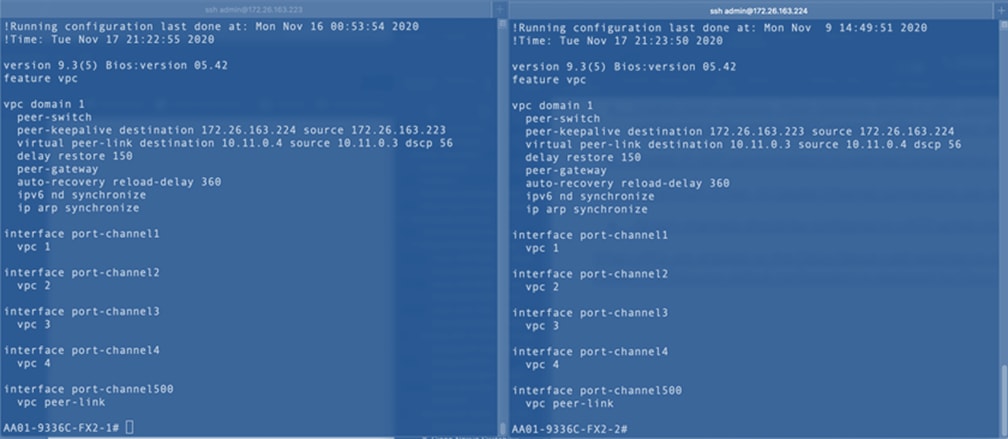
Figure 7 shows the configuration deployed on the Cisco Nexus Leaf switches by Cisco DCNM for the vPCs going to the Cisco UCS domain and NetApp AFF cluster.
![]() The configuration aligns with the recommendations previously mentioned.
The configuration aligns with the recommendations previously mentioned.
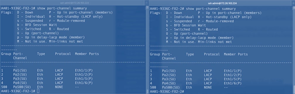
The four vPCs deployed on the leaf switches are: vPCs [1-2] to the Cisco UCS Domain (Fabric Interconnect A, Fabric Interconnect B) and vPCs [3-4] to the NetApp AFF A300 cluster. The peer keepalive uses the OOB management network in this design. Virtual peer-links are also used as it is supported on this leaf switch pair. Cisco DCNM will allow virtual peer-links only on those leaf switches that support this capability preventing administrators from enabling an unsupported feature and saves on the time required to determine support.
Figure 7. vPC Configuration – Deployed by Cisco DCNM
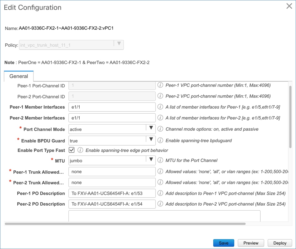
LACP is deployed in Active Mode as per the vPC recommendations.
Figure 8. LACP Mode on vPCs – Deployed by Cisco DCNM
Spanning Tree Considerations
The spanning tree best-practices and other considerations for deploying vPCs are provided below. Cisco DCNM follows and aligns with these recommendations and implements them (by default) when deploying vPCs.
● Peer-switch (part of vPC configuration) is enabled which allows both switches to act as root for the VLANs without modifying the spanning tree priority.
● Loopguard is disabled by default
● BPDU guard and filtering are enabled by default
● Bridge assurance is only enabled on the vPC Peer Link
● Ports facing the NetApp storage controller and Cisco UCS are defined as “edge” trunk ports
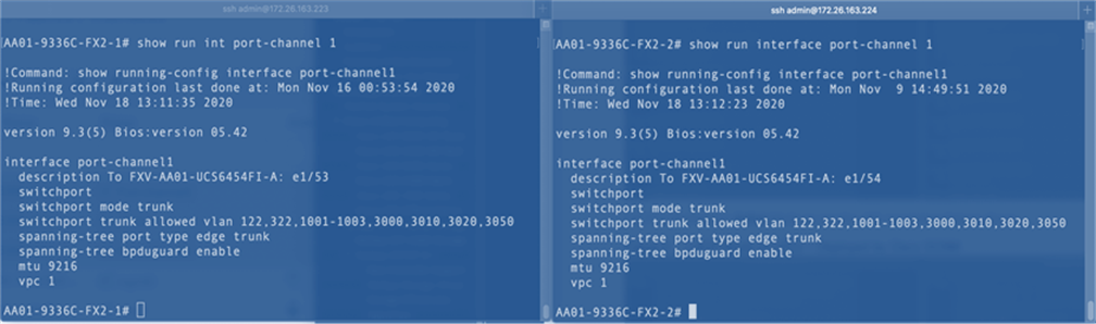
Figure 9 shows the spanning tree and other configuration deployed on the Cisco Nexus Leaf switches by Cisco DCNM for the vPCs that connect to the Cisco UCS domain and NetApp AFF cluster.
![]() The configuration aligns with the recommendations previously mentioned.
The configuration aligns with the recommendations previously mentioned.
Figure 9. Spanning Tree Configuration – Deployed by Cisco DCNM
Cisco provides two data center network solutions or fabrics to meet the needs of large-scale, modern data centers:
● Cisco Application Centric Infrastructure (ACI)
● VXLAN Multiprotocol Border Gateway Protocol (MP-BGP) Ethernet VPN (EVPN)
The data center fabric in this FlexPod design is based on VXLAN MP-BGP EVPN managed using Cisco Data Center Network Manager (Cisco DCNM). Cisco DCNM brings agility and simplicity to the FlexPod solution by providing a centralized controller for automating the Day-0 deployment of a best-practices based VXLAN fabric and for Day-1 and Day-2 operations and management of the fabric.
For FlexPod designs using Cisco ACI and traditional network architectures, see Design Zone for Data Center on cisco.com.
Cisco Intersight
Cisco Intersight is a Software-as-a-Service (SaaS) infrastructure management platform that is augmented by other intelligent systems. It provides global management of the Cisco Unified Computing System™ (Cisco UCS) infrastructure anywhere. Intersight provides a holistic approach to managing distributed computing environments from the core to the edge. The Cisco Intersight virtual appliance (available in the Essentials edition) provides customers with deployment options while still offering all the benefits of SaaS. This deployment flexibility enables organizations to achieve a higher level of automation, simplicity, and operational efficiency.
Cisco UCS systems are fully programmable infrastructures. Cisco Intersight includes a RESTful API to provide full programmability and deep integrations with third-party tools and systems. The platform and the connected systems are DevOps-enabled to facilitate continuous delivery. Customers have come to appreciate the many benefits of SaaS infrastructure management solutions. Cisco Intersight monitors the health and relationships of all the physical and virtual infrastructure components. Telemetry and configuration information is collected and stored in accordance with Cisco’s information security requirements. The data is isolated and displayed through an intuitive user interface. The virtual appliance feature enables users to specify what data is sent back to Cisco with a single point of egress from the customer network.
This cloud-powered intelligence can assist organizations of all sizes. Because the Cisco Intersight software gathers data from the connected systems, it learns from hundreds of thousands of devices in diverse customer environments. This data is combined with Cisco best-practices to enable Cisco Intersight to evolve and become smarter. As the Cisco Intersight knowledge base increases, trends are revealed, and information and insights are provided through the recommendation engine.
In addition to Cisco UCS server status and inventory, Cisco Intersight Essentials provides the Cisco UCS server Hardware Compatibility List (HCL) check for Cisco UCS server drivers. In this FlexPod validation, the HCL check can be used to verify that the correct Cisco UCS VIC nfnic and nenic drivers are installed.
VMware vSphere is a virtualization platform for holistically managing large collections of infrastructure (resources-CPUs, storage, and networking) as a seamless, versatile, and dynamic operating environment. Unlike traditional operating systems that manage an individual machine, VMware vSphere aggregates the infrastructure of an entire data center to create a single powerhouse with resources that can be allocated quickly and dynamically to any application in need.
vSphere 7.0 brings a number of improvements and simplifications including, but not limited to the following:
● Fully featured vSphere Client (HTML5) client. The Flash-based vSphere Web Client has been deprecated and is no longer available.
● Improved Distributed Resource Scheduler (DRS) – a very different approach that results in a much more granular optimization of resources.
● Assignable Hardware – a new framework that was developed to extend support for vSphere features when customers utilize hardware accelerators.
● vSphere Lifecycle Manager – a replacement for VMware Update Manager, bringing a suite of capabilities to make lifecycle operations better.
● Refactored vMotion – improved to support today’s workloads.
For more information about VMware vSphere and its components, see: https://www.vmware.com/products/vsphere.html.
Figure 10 shows the VMware vSphere built on FlexPod components and the network connections for a configuration with the Cisco UCS 6454 Fabric Interconnects and 25 Gb Ethernet compute networking. This design was validated and has port-channeled 25 Gb Ethernet connections between the Cisco UCS 5108 Blade Chassis and the Cisco UCS Fabric Interconnects, port-channeled 25 Gb Ethernet connections between the Cisco UCS C-Series rack-mounted servers, and 40/100 Gb Ethernet connections between the Cisco UCS Fabric Interconnect and Cisco Nexus 9000s, and 40 Gb Ethernet connections between Cisco Nexus 9000s and NetApp AFF A300 storage array. The Ethernet connections in the topology can be scaled up or down to meet the bandwidth requirements of the solution.
Figure 10. FlexPod Validated Topology
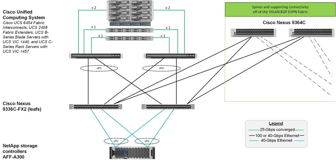
The reference hardware configuration minimally includes:
● Two Cisco Nexus 9336C-FX2 leaf switches
● Two Cisco Nexus 9364C spine switches
● Two Cisco UCS 6454 fabric interconnects connected to Cisco UCS 5108 Blade server chassis with Cisco UCS 2408 fabric extenders and Cisco UCS B-series servers or Cisco UCS C-series rack-mount servers
● One NetApp AFF A300 (HA pair) running ONTAP 9.7 with Disk shelves and Solid State Drives (SSD)
Network Design - Cisco VXLAN MP-BGP EVPN Fabric
Cisco’s VXLAN MP-BGP EVPN fabric delivers a highly flexible, scalable, and resilient network architecture for the modern data center. The network fabric brings Cisco’s industry leading, innovative suite of products and technologies that uses proven, standards-based protocols and low-latency, high-bandwidth links to deliver a programmable infrastructure with orchestration and management tools to meet the agility and needs of modern applications.
VXLAN is a network overlay technology that uses network virtualization on an underlay network to extend edge networks across a shared data center network. The edge networks are typically Layer 2 VLAN based networks that VXLAN transports as overlay networks across a shared IP underlay network. By decoupling the physical network in the underlay network from the virtual network in the VXLAN overlay, VXLAN provides a flexible infrastructure that can meet the needs of modern applications. The network virtualization prevents physical network and topology constraints from limiting endpoint location or workload positioning, thereby enabling workloads to be placed anywhere within a data center or across data centers. The Layer 2 extension provided by VXLAN also enables endpoints and applications to have Layer 2 adjacency across an IP network, regardless of where they are located.
VXLAN uses IP/UDP to tunnel edge networks or VLAN segments across a shared data center network, enabling Layer 2 segments to span physical Layer 3 networks. The Layer 2 Ethernet frames are transported using a MAC in IP/UDP encapsulation as shown below and uses a well-known destination UDP port number of 4789.
Figure 11. VXLAN Packet Format
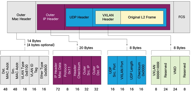
Each edge network or Layer 2 segment is uniquely identified by a VXLAN Network Identifier (VNI) within the shared data center network infrastructure. VXLAN uses a 24-bit identifier which enables it to support up to 16 million Layer 2 segments. VLANs used a 12-bit identifier which limits the number of Layer 2 segments it can support to 4094. VXLAN therefore provides significantly higher scalability when compared to VLANs.
In VXLAN, a software or hardware entity that can map the traffic from endpoints in the edge networks to VXLAN segments and encapsulate/decapsulate the traffic are referred to as VXLAN Tunnel Endpoints (VTEPs). VTEPs are also VXLAN gateways as they connect Layer 2 segments in the edge network to a VXLAN segment in the shared data center network. VTEPs originate and terminate the VXLAN tunnels within a data center network to transport the overlay traffic. The source and destination IP addresses of the tunnel are the source and destination VTEP IP addresses respectively. VTEPs can be a physical switch such as Cisco Nexus or it could be a hypervisor running on a server. On Cisco switches, VTEPs are defined as a logical interface, specifically the Network Virtualization Edge (NVE) interface or interface nve1 and uses the IP address of a loopback interface for VXLAN encapsulation/decapsulation. On Cisco Nexus switches, the VXLAN encapsulation/decapsulation is done in hardware unlike software-based VTEPs. This ensures line-rate performance regardless of packet sizes which is critical for application performance across a VXLAN fabric.
For a given VXLAN segment, VTEPs also learns endpoint MAC addresses from received traffic; traffic received can be from an endpoint in a local edge network or from a remote VTEP in the case of remote endpoints. MAC addresses learned from a remote Layer 2 segment are associated with a remote VTEP’s IP address.
VXLAN can also leverage the benefits that Layer 3 routing brings by using an IP based underlay as the transport network. VXLAN traffic can better utilize the underlying shared infrastructure by leveraging IP-based equal-cost multipath (ECMP) routing to make use of all available network paths, especially when using a CLOS-based topology that will typically have multiple equal-cost paths between edge networks.
VXLAN therefore provides the same network segmentation and capabilities as a VLAN network but with greater flexibility, extensibility and with better utilization of the underlying network infrastructure, enabling organizations to build large-scale, shared, multi-tenant data centers.
VXLAN MP-BGP EVPN Design Considerations
In this section, the design factors considered, and options selected for the FlexPod VXLAN fabric are discussed, This includes best-practices that are built into the VXLAN implementation on Cisco Nexus switches that are used in this FlexPod design.
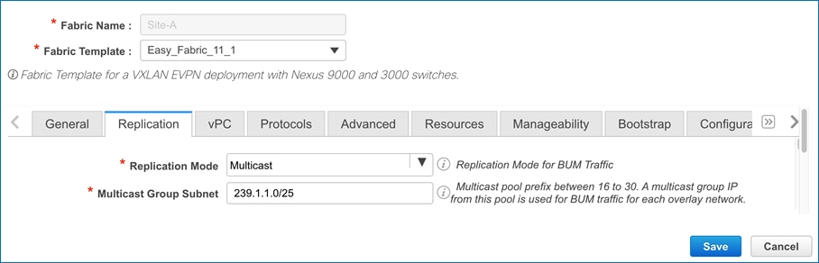
● Broadcast Unknow Unicast and Multicast (BUM) traffic Handling: Endpoints in Ethernet networks can send BUM traffic to multiple destinations if they are in the same Layer 2 broadcast domain. When the ethernet segment is extended across a VXLAN data center network, the ethernet endpoints should still be able to operate as they normally do, without any changes to the endpoints. To achieve this, the VXLAN fabric must provide a similar mechanism for forwarding BUM traffic across an IP transport network. VXLAN has two options for providing this across an IP network. It can use either IP Multicast in the IP underlay network or Ingress Replication on each VTEP. With ingress replication, the local VTEP will replicate the BUM traffic and send an individual copy to each remote VTEP. If IP multicast is used, the VXLAN fabric will map each VXLAN segment to an IP multicast group. Each VTEP will then use Internet Group Management Protocol (IGMP)/Protocol Independent Multicast (PIM) to join that multicast group in order to forward BUM traffic across the underlay network. Cisco recommends using IP multicast when possible as it is a more efficient method of forwarding multi-destination BUM traffic to multiple remote VTEPs. It also limits the scope of the flooding to only those VTEPs that have endpoints in a given VXLAN segment. Cisco DCNM’s Fabric Builder used in this solution, uses Cisco’s best practice recommendations to deploy the VXLAN fabric and uses IP Multicast by default. This FlexPod design will therefore use IP multicast for forwarding BUM traffic across the VXLAN fabric.
● Address Learning and VTEP discovery: Ethernet switched networks use a data-plane flood-and-learn mechanism to ensure reachability to unknown or yet-to-be learned endpoints. This data plane method can also be used in a VXLAN fabric by using the IP multicast group associated with each ethernet/VLAN segment to flood traffic across the fabric. The data-plane method will provide endpoint reachability, address-learning as well as discovery of remote VTEPs. However, large amounts of multicast traffic can also limit the scalability of the data center fabric. To overcome the limitations of a flood-and-learn approach, IETF standardized a more efficient, control-plane method using MP-BGP EVPN to enable address learning and VTEP discovery in VXLAN networks. MP-BGP provides higher scalability and more flexibility and control through policies. MP-BGP is also unique in that can be used to advertise both Layer 2 endpoint (MAC, IP) reachability as well as Layer 3 reachability (IP Prefixes) – both of which are needed in a data center fabric to provide integrated routing and bridging for edge networks. This FlexPod solution will therefore use MP-BGP EVPN for the VXLAN data center fabric instead of flood-and-learn.
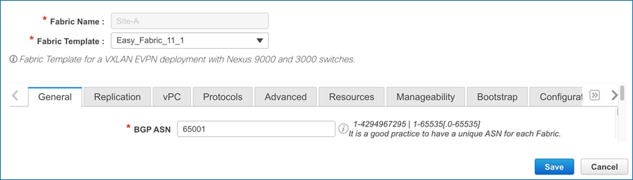
Multi-tenancy: MP-BGP is designed for multi-tenancy and can provide the same in a VXLAN-based data center fabric. MP-BGP EVPN uses the same concepts as MPLS-based Layer 3 VPNs (L3VPNs) to maintain tenant separation in the control plane. Similar to MPLS L3VPNs, a Route Distinguisher (RD) will ensure the global uniqueness of addresses belonging to different VPNs (or VRFs) when advertising them to other BGP peers and route-targets (RT) will associate the addresses to a VRF for flexible exporting and importing of routes between peers in the same VRF and across VRFs. In the data-plane, VXLAN will use VNIDs to provide segmentation in the overlay network by mapping edge networks to a VNID and by enforcing VNID and VRF boundaries. This FlexPod design uses a Foundation tenant for all compute and storage infrastructure related connectivity and management. A separate Application tenant is used for applications hosted on the infrastructure. Customers can deploy additional tenants as needed. The RD and RT that is deployed for the Foundation VRF on a leaf switch in this FlexPod design is shown below.
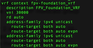
● ARP Suppression: By using a control plane method (MP-BGP) for address learning, not all ARP traffic will need to be flooded across a VXLAN data center network. When endpoints in an ethernet/VLAN segment that connect to a VXLAN fabric originate an ARP Request with a destination = broadcast MAC address, VXLAN will flood that traffic across the fabric to all remote segments using the multicast-group address associated with that segment. However, if ARP suppression is enabled, Cisco Leaf switches will inspect any ARP requests it receives from the local ethernet/VLAN network and do a local lookup to see if it has learned the address of that endpoint via MP-BGP. If it has, it will respond to that ARP request locally and it will not flood that ARP request across the VXLAN fabric.
● Integrated Routing and Bridging (IRB): VXLAN with MP-BGP EVPN supports IRB where a VXLAN gateway or Leaf switch provides both Layer 2 and Layer 3 forwarding for locally attached ethernet/VLAN segments. Each VTEP can therefore provide pure Layer 2 switching or it can act as a default gateway and provide Layer 3 forwarding. The edge networks can be mapped to a Layer 2 or Layer 3 VXLAN segment or VNI and MP-BGP EVPN can be used to advertise endpoint reachability, MAC address, IP address or IP prefixes as needed. Layer 2 VNI enables Layer 2 extension to bridge Layer 2 segments across a VXLAN data center network. Layer 3 VNI provides tenant or Layer 3 segmentation to support multi-tenancy. VXLAN with MP-BGP EVPN standard supports two types of IRB: Symmetric IRB and Asymmetric IRB. Cisco Nexus switches only support symmetric IRB as it is more scalable and less complex from a configuration perspective. Therefore, the VXLAN fabric in this FlexPod solution will use Symmetric IRB.
● Distributed Anycast Gateway: To facilitate flexible workload placement, endpoint mobility and optimal traffic forwarding across a data center fabric, VXLAN uses distributed anycast gateways whereby each Leaf switch acts a local gateway for a given edge network. To enable this, all Leaf switches in the same Layer 3 VXLAN network are configured to use the same gateway IP address. The MAC address is a virtual anycast gateway mac-address which is also configured to be the same across all Leaf switches. This ensures that the ARP entries for the Gateway IP are still valid even when endpoints moves between leaf switches. VXLAN fabrics therefore do not require HSRP or FHRP and routed traffic between leaf switches will be locally switched, reducing network latency and uplink bandwidth utilization. The VXLAN fabric in this FlexPod solution will use distributed anycast gateways as the default gateway for all Layer 3 VXLAN networks.
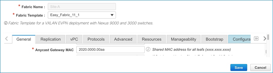
● Maximum Transmission Unit (MTU): VXLAN uses a MAC-in-IP/UDP encapsulation which results in a 50 Byte overhead for every ethernet frame forwarded by the fabric. Per the IETF VXLAN standard, a VTEP must not fragment VXLAN packets. Though intermediate switches in the fabric can fragment, Cisco’s recommendation is to avoid all fragmentation in the fabric. Therefore, the MTU within the fabric should be at least 50 Bytes higher than the MTU of the edge traffic being transported by the fabric. Cisco DCNM’s Fabric Builder generally uses best practice recommendations when deploying a VXLAN fabric and uses a default MTU of 9216B. The Cisco Nexus 9000 series switches used in this FlexPod solution supports this MTU and therefore all interfaces in the fabric are deployed to use this MTU. This ensures that the fabric can support endpoints and applications in the edge network that use jumbo frames.
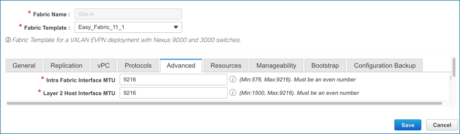
● Underlay Interface Addressing: The connectivity between switches in a VXLAN fabric should be deployed using IP unnumbered or as point-to-point with a /30 or /31 subnet mask to limit the number of IP addresses required for the underlay. Alternatively, IPv6 can also be used in the underlay network. The interface addressing for the VXLAN fabric in this FlexPod design is shown below.
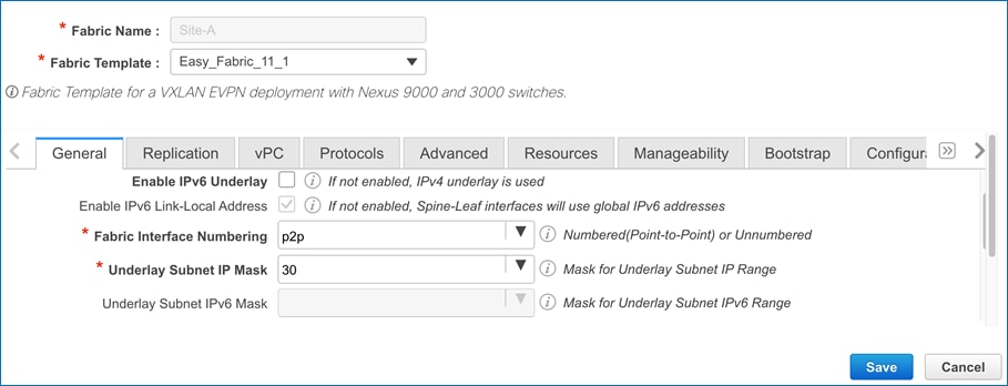
● Underlay Routing Protocol: The underlay routing protocol is responsible for VTEP-to-VTEP reachability in a VXLAN fabric. There are multiple options but generally an Interior Gateway Protocol (IGP) such as OSPF or ISIS is recommended as it can make use of the multiple equal cost paths between leaf switches that are inherent in a CLOS-based spine-leaf topology while also providing rapid convergence around network failures. Alternatively, BGP can also be used but it may require some changes to support multi-pathing in the underlay. The underlay routing protocol used in the FlexPod VXLAN fabric is shown below.
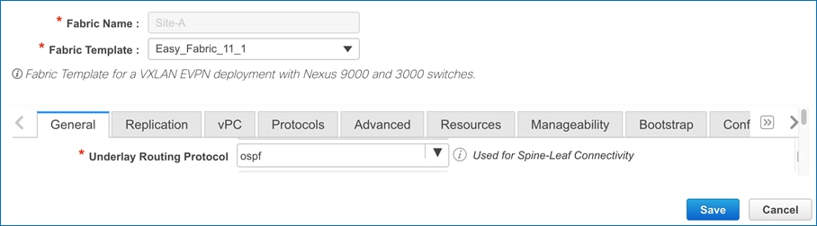
● Underlay Loopback Addressing: Multiple loopback interfaces are recommended in a VXLAN fabric as router ID for the underlay routing protocol used and as VTEP IP address used as source and destination for VXLAN encapsulated packets. The underlay loopbacks used in the FlexPod VXLAN fabric is shown below.

● Underlay IP Multicast: As discussed earlier, IP multicast is recommended in a VXLAN fabric for efficient distribution of BUM traffic. To deploy IP multicast in the IP underlay network requires a multicast routing protocol. Two commonly used routing protocols are Protocol Independent Multicast (PIM) in Sparse-Mode (PIM-ASM) and Bidirectional mode (PIM-Bidir). Both PIM protocols require Rendezvous-Points, redundantly deployed. Cisco recommends deploying redundant RP functionality on spine switches – a separate loopback is recommended for RP as well. The underlay IP multicast setup for the VXLAN fabric in this FlexPod solution is shown below.
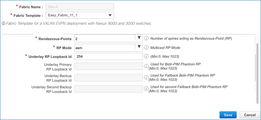
● Underlay IP Multicast Scaling: As discussed earlier, each VXLAN segment is mapped to a multicast group for forwarding BUM traffic. However, as the number of VXLAN segments grow, the number of multicast groups and the forwarding states that needs to be maintained on the fabric switches grows. For this reason, Cisco recommends mapping multiple VXLAN segments to a single IP multicast group in the VXLAN fabric. This reduces the control plane resource usage, but it does mean that a given multicast-group now sees the BUM traffic for multiple segments and therefore, VTEPs that might not otherwise need to see it. However, this does not mean one edge network will see or receive the BUM traffic for another edge network. The VTEP will only forward those packets whose VNID in the VXLAN header matches the VNID of local segment. By default, Cisco DCNM will default to using the same multicast group as shown below. Customers can change this to suit the needs of their deployment.
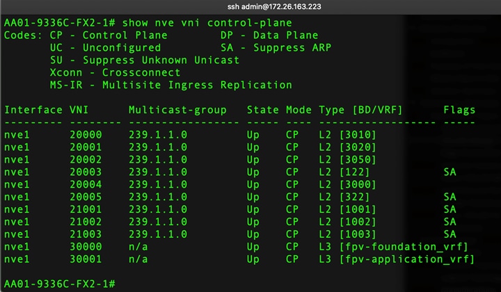
● Overlay Routing Protocol: As discussed earlier, BGP, specifically internal BGP (iBGP) is the recommended overlay routing protocol in VXLAN fabrics. iBGP requires a full mesh between all switches in the underlay network which can be avoided by using route-reflectors (RR) that all switches peer with. These route-reflectors are typically deployed in a central location and in a spine-leaf topology, spine switches is an obvious location for implementing this functionality. The route-reflectors will reflect any EVPN routes received from VTEP leaf switches to all other VTEP leaf switches that it is peered with. The RRs setup for BGP used as overlay routing protocol for VXLAN fabric in this FlexPod solution is shown below.
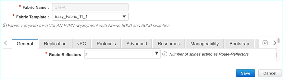
The key architectural buildings blocks of a Cisco VXLAN fabric are:
● Cisco Data Center Network Manager (Optional): Cisco DCNM, though optional, is highly recommended and an integral and unifying point of control for automating and managing the end-to-end VXLAN data center fabric. The Cisco VXLAN fabric is built on a network of individual components that are provisioned and managed as a single entity. Cisco DCNM can discovery the fabric topology, including software and hardware capabilities of individual switches, automate the creation and provision of a VXLAN fabric using Cisco recommended best-practices as default options, and easy integration to non-VXLAN infrastructures by providing templates for common use cases. Cisco DCNM can also provide day-2 operational support by providing a common point of access and control to monitor the fabric and for day-2 use cases such as backup and restore of the fabric configuration and fabric upgrades, including image and configuration repository.
● Cisco Nexus 9000 Series Switches: In a data center, the VXLAN fabric is typically built on a network of Cisco Nexus 9000 series switches that provide low-latency, high-bandwidth connectivity with industry proven protocols and innovative technologies to create a flexible, scalable, and highly available architecture. VXLAN with MP-BGP EVPN is supported on several models of Nexus 9000 series switches and line cards. The selection of a given switch as an VXLAN spine or leaf switch will depend on a number of factors such as physical layer connectivity (1/10/25/40/50/100-Gbps) requirements and other features such as FEX aggregation support, hardware analytics and telemetry, encryption support, Multi-Site support etc.
● Spine Switches: The spine switches in a VXLAN fabric are essentially core switches that provide high-speed (40/100-Gbps) connectivity between leaf switches in the VXLAN fabric. The spine switches also provide centralized functionality for the operation of the IP underlay and VXLAN overlay networks. Rendezvous points for PIM IP multicast and Route Reflectors for MP-BGP are two services that are typically deployed on the Spine switches. Spine switches in a VXLAN fabric can also operate as a Super Spine and in multiple Border Spine roles (Border Spine, Border Gateway Spine, Border Super Spine, Border Gateway Super Spine) for connecting to external networks and to other fabrics in a VXLAN multi-site deployment.
● Leaf Switches: These are essentially Top-of-Rack (ToR) switches that endpoints and devices in the edge network connect into. They provide ethernet connectivity to devices such as servers, firewalls, storage arrays and other network elements in the edge network. These switches will typically have 40/100GbE uplink ports for high-speed connectivity to spine switches and access ports that support a range of speeds (1/10/25/40GbE) for connecting to servers, storage, and other network devices. Leaf switches provide access layer functions such as traffic classification, policy enforcement, L2/L3 forwarding of edge traffic etc. Similar to Spine switches, Leaf switches in the VXLAN fabric can also operate as a Border switch and Border Gateway switch to connect to external networks and to other fabric in multi-site deployment. The criteria for selecting a specific Cisco Nexus 9000 model as a leaf switch will be different from that of a spine switch.
The VXLAN fabric is deployed and managed using Cisco DCNM in this FlexPod solution. The design constructs in Cisco DCNM are critical to the overall design and deployment of a VXLAN data center network fabric. These design constructs include:
● Fabrics: In Cisco DCNM, a VXLAN fabric is a group of switches deployed as a two-tier spine-leaf topology with connectivity to each other as needed. The fabric can also be an external fabric representing connectivity to an external gateway switch or router that is unmanaged or managed by Cisco DCNM and provide connectivity to external networks. These fabrics can be single-site fabrics or can be part of a larger multi-site domain (MSD). The switches in the fabric can be discovered with minimal configuration and added to the topology through LLDP by specifying a starting or Seed IP for the discovery. The switches in the fabric can also be configured from scratch with no start-up configuration using Power On Auto Provisioning (POAP).
● Roles: Each switch in a VXLAN fabric has a role that determines the type of connectivity and functionality it provides for users of the network fabric. Cisco DCNM determines the primary configuration on a switch in the fabric based on the role that is selected. The role is specified immediately after discovering and adding the switch to a given fabric. The roles can be as simple as Spine or Leaf or it can be any number of Border Leaf or Border Spine roles such as Border, Border Spine, Border Gateway, Border Gateway Spine. It can also be a Super Spine and associated border functionalities such as Border Super Spine or Border Gateway Super Spine.
● Interfaces: To connect the switches in the fabric and configure the interfaces for port-channel or virtual port-channeling, Interfaces in Cisco DCNM can be used to configure the following types of interfaces using templates.
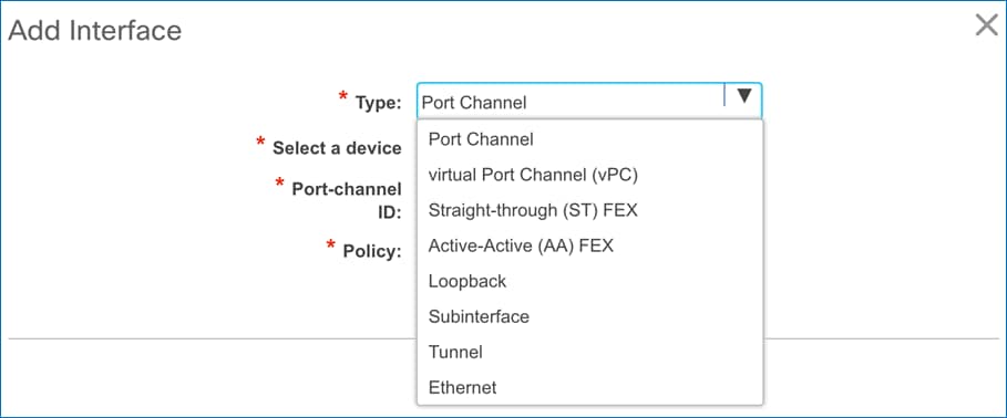
The type of interface selected will determine the configuration options as shown below. Note that for virtual Port-channels, two leaf switches must be paired as a vPC leaf switch pair before the vPC interfaces can be configured.
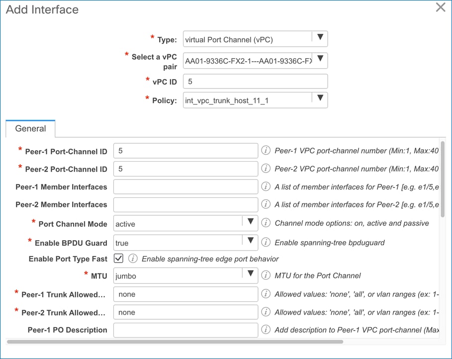
● Networks and VRFs: Multi-tenancy in a VXLAN fabric is enabled through Virtual Routing and Forwarding (VRF) instances with the networks being Layer 2 or Layer 3 access layer networks that connect to endpoints in the edge network. A tenant is a unit of isolation and in a VXLAN fabric, the Virtual Routing and Forwarding (VRF) instance represents a tenant. In Cisco DCNM, Networks & VRFs are used to deploy network overlays across the VXLAN fabric that belong to a tenant VRF. The tenants or VRFs used in this FlexPod design are shown below. Customers can deploy additional tenants as needed to meet the needs of their deployment.
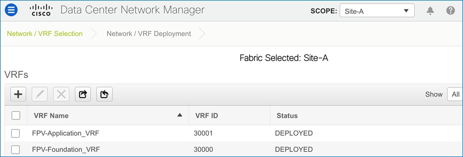
The Layer 2 and Layer 3 networks used in this FlexPod design are shown below. Customers can deploy additional networks as needed.
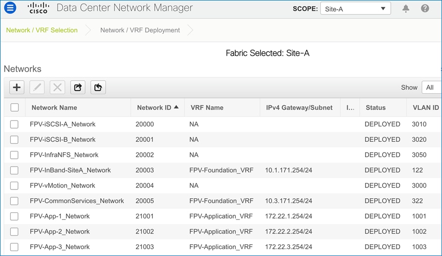
The data center network fabric used in this FlexPod solution is a Cisco DCNM managed VXLAN MP-BGP EVPN fabric. As stated before, the fabric uses two-tier, CLOS-based spine-leaf architecture built using Cisco Nexus 9000 series switches. The fabric is highly resilient with no single point of failure and incorporates technology and product-specific best practices, The fabric is horizontally scalable by adding links to increase the bandwidth in a given segment or by extending the overall fabric by adding more leaf and spine switch pairs – without compromising on latency or performance.
The high-level topology for the data center fabric used in this FlexPod solution is shown in Figure 12.
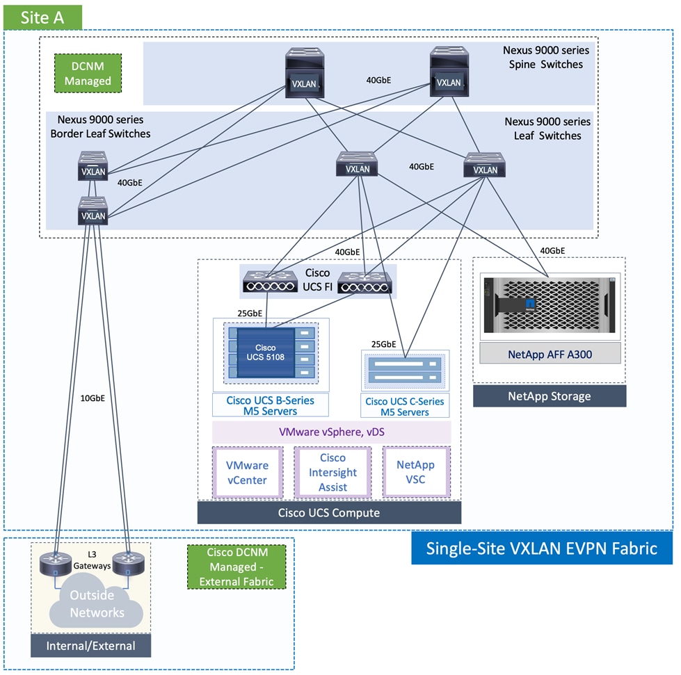
The data center fabric is a single VXLAN fabric with a pair Nexus 9000 series spine switches and two pairs of leaf switches. One set of leaf switches are used for connecting to FlexPod compute and storage infrastructure while a separate of pair of leaf switches are used as Border Leaf switches for connecting to external networks outside the VXLAN fabric. For scalability, Cisco recommends using separate border leaf switches, but it is possible to use a single pair of leaf switches for connecting to the FlexPod infrastructure and for external connectivity. All leaf switches connect to spine switches using 40GbE links with no direct links between spine switches nor the leaf switches. Cisco DCNM, situated outside the fabric, is used to provision and deploy this fabric using the Easy_Fabric_11_1 template. The template supports IPV4 or IPV6 addressing and OSPF or ISIS for the Interior Gateway Protocol (IGP) in the IP underlay network, and Internal BGP (iBGP) in the overlay network. In this design, all links in the underlay are deployed as point-point links using an IPv4 /30 subnet mask and uses OSPF for routing. As discusses earlier, the BUM traffic can be flooded across the VXLAN fabric using either IP multicast or ingress replication – this design uses IP multicast and PIM-ASM for multicast routing though PIM-ASM and Bidir-PIM are both supported as multicast routing protocols in a Cisco VXLAN fabric. PIM-ASM requires Rendezvous-Points (RPs) required by PIM-ASM are deployed on the spine switches. Two RPs are deployed for high-availability, one on each spine switch. All interfaces in the fabric are configured for jumbo MTU.
VXLAN Fabric Design – Core Connectivity
The detailed physical topology of the VXLAN MP-BGP EVPN core and Cisco Nexus 9000 series switches used as spine and leaf switches are shown in Figure 13.
Figure 13. Physical Topology – Core Connectivity
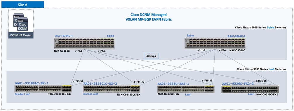
The leaf switch pair on the left are the optional border leaf switches for connecting to external networks. The leaf switch pair on the right side of the figure are the leaf switches that connect to the FlexPod compute and storage infrastructure using vPCs. All links in the core are 40GbE links.
VXLAN Fabric Design - Edge Connectivity
Edge connectivity is the connectivity from the VXLAN fabric leaf switches to devices or endpoints in the edge network. For Layer 2 connectivity, Cisco switches support link aggregation using Link Aggregation Control Protocol (LACP) to connect to an endpoint in the edge network. The connectivity can be a port-channel (PC) from a single leaf switch or a virtual port-channel (vPC) from a pair of leaf switches acting as a single logical entity. Link aggregation provides both higher aggregate bandwidth and resiliency but vPCs provide a higher level of resiliency by providing both node and link-level resiliency and therefore preferred when possible.
In this FlexPod design, connectivity to Cisco UCS compute and Cisco NetApp AFF cluster use different vPCs from the same access layer switches as shown in the following figures.
Figure 14. VXLAN Fabric Design – Connectivity to Cisco UCS Compute Domain
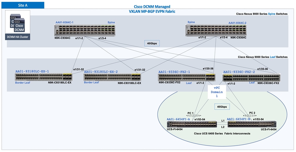
Figure 15. VXLAN Fabric Design – Connectivity to NetApp AFF 300 Storage Cluster
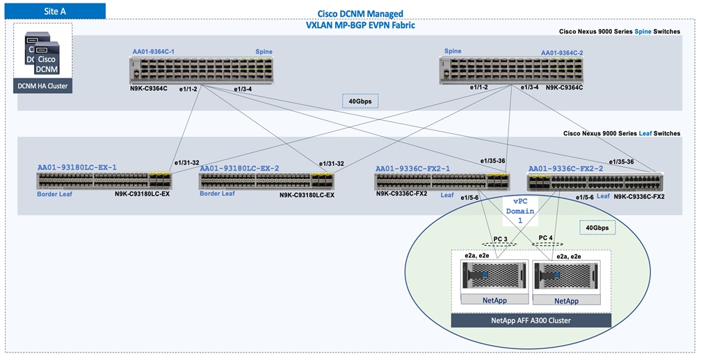
The default vPC setup parameters used for the vPC connections to edge devices in this FlexPod solution are shown below:
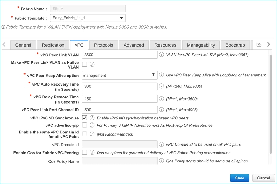
VXLAN Fabric Design - External Connectivity
External connectivity refers to the connectivity from the VXLAN data center fabric to networks outside the VXLAN fabric, either internal or external to the Enterprise. In this FlexPod design, external connectivity is necessary to connect to networks and services shown in Figure 16. This connectivity is critical for deploying, managing, and operating the FlexPod infrastructure and the VXLAN fabric that it connects.
Figure 16. External Connectivity – For Access to Outside Networks and Services
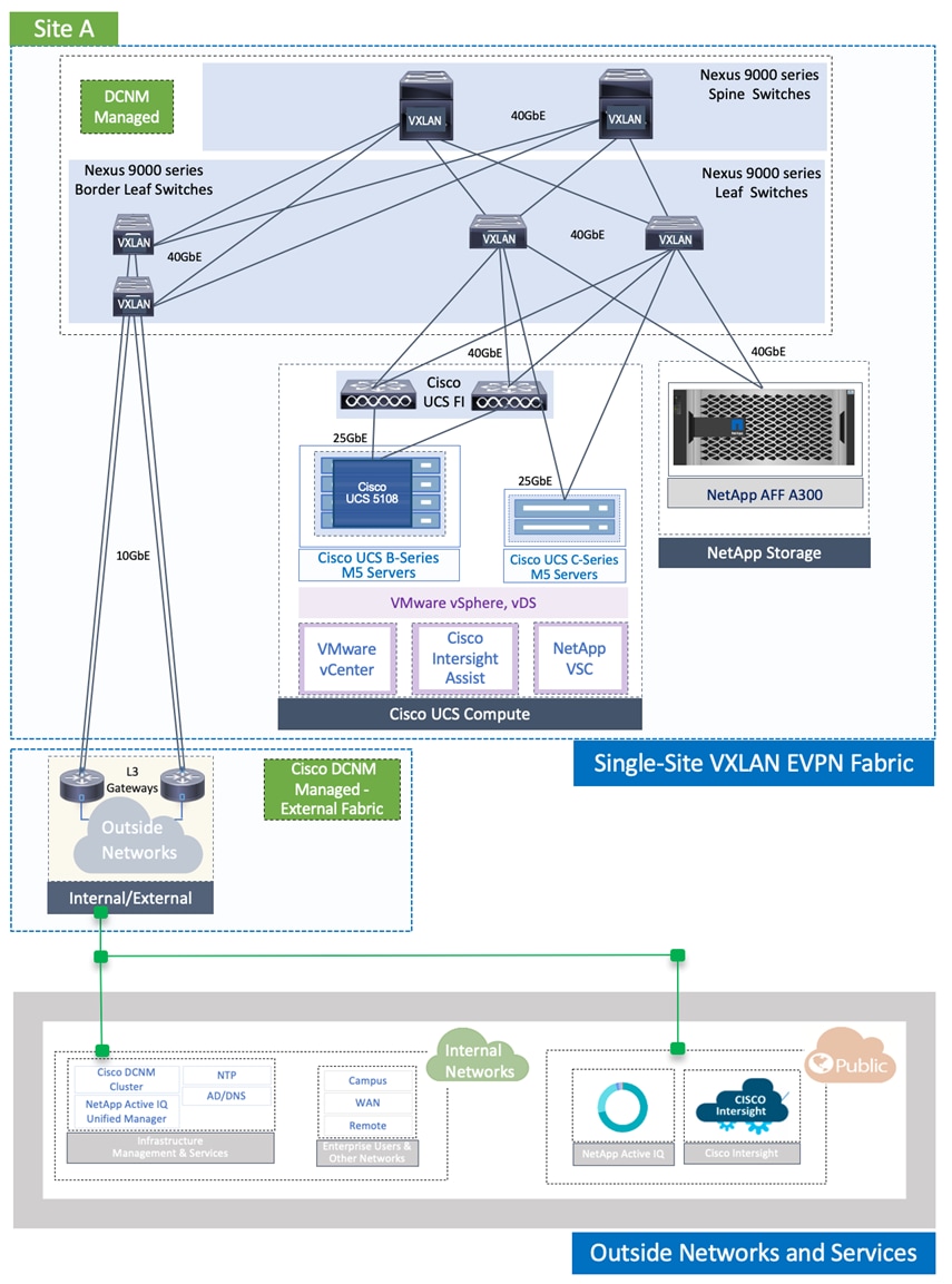
The external connectivity can be as follows:
● Layer 2 connectivity maybe necessary when connecting to an existing data center network and the ability to migrate workloads between the networks is required.
● Layer 3 connectivity is generally used in all other scenarios including connectivity to campus, WAN, and Internet sites. Layer 3 connectivity can extend existing multi-tenancy within the VXLAN fabric to external routed domains or it can provide all tenants access to a shared or common service such as cloud services the Internet. There are multiple options for achieving Layer 3 connectivity to outside networks from Cisco VXLAN fabric – these include an MPLS hand-off by connecting each VRF to a VRF in the MPLS-VPN network or IP handoff by using different IEEE 802.1Q tags to connect each VRF to a VRF-Lite setup in the external gateway.
In this FlexPod design, the external connectivity from the VXLAN fabric uses IP handoff to a VRF-Lite setup. To deploy this connectivity, Cisco DCNM uses a separate fabric for the external gateways in the external network. This external fabric is deployed using the External_Fabric_11_1 template. The logical connectivity between the external fabric (SiteA_External) and the VXLAN fabric (Site-A) is as shown in the following topology from Cisco DCNM.
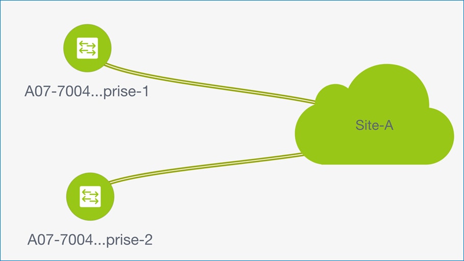
The physical connectivity between the Site-A fabric and SiteA_External fabric are shown in Figure 17. The external gateways are a pair Cisco Nexus 7000 series switches connected using redundant 10GbE links to the Border leaf switches in the Site-A fabric.
Figure 17. VXLAN Fabric Design – Connectivity to External Networks
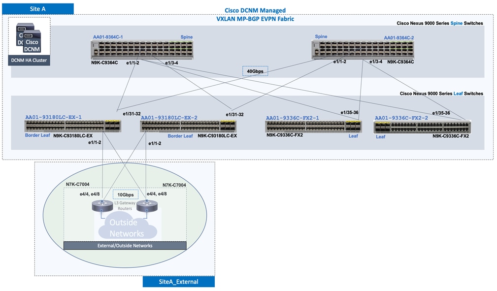
Cisco DCNM configuration for external connectivity on the Site-A fabric side is shown below. The external gateway in this device will be managed and therefore, the VRF-Lite setup on the external gateway device will also be deployed by Cisco DCNM.
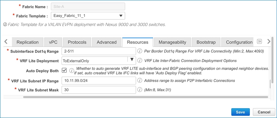
Cisco DCNM setup for the external gateway switches that are part of a separate external fabric (SiteA_External) is shown below. The external gateways are in a different BGP Autonomous System. The external gateways in this design are also being managed by Cisco DCNM which means that DCNM can deploy the VRF-Lite configuration on the external gateway switches to connect the border leaf switches in the Site-A fabric.
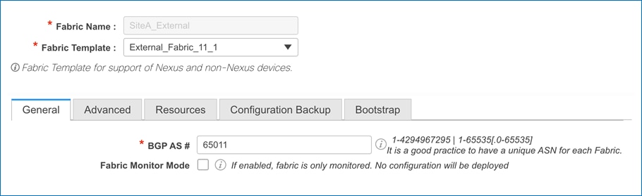
The access-layer connectivity between the Site-A fabric and SiteA_External fabric is enabled through Inter-Fabric links that connect routed VRF VLAN-tagged interfaces on the border leaf switches in the Site-A fabric to routed, VLAN tagged interfaces in a VRF-Lite setup on the external gateway switches in the SiteA_External fabric. This is done for each tenant that require connectivity to the external fabric. In this FlexPod design, this connectivity is only enabled for the FPV-Foundation_VRF – however, the same process can be used for any tenant that requires external connectivity. The Inter-Fabric connectivity between the switches in the two fabrics are shown below:
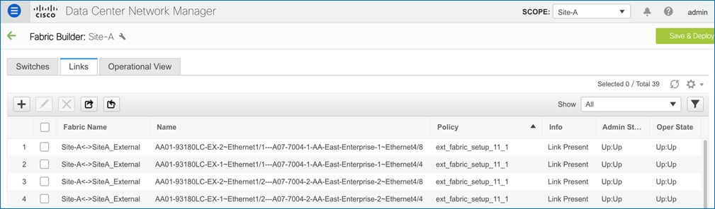
The Fabric Name shows both fabrics for an inter-fabric connection and the corresponding policy shows that it is an external fabric setup policy.
The VXLAN MP-BGP EVPN is designed for multi-tenancy. Multi-tenancy enables Enterprises to partition the fabric along organizational or functional lines. The tenancy design can also be based on different factors. The tenancy design in this solution is based on connectivity requirements. Two tenants are used in this FlexPod design: FPV-Foundation_VRF and FPV-Application_VRF. The Foundation tenant is used for all FlexPod compute, storage, and virtual infrastructure connectivity in the FlexPod solution. It also includes connectivity for any management or operational tools that are used to manage the infrastructure. The Application tenant on the other hand is for any application workloads hosted on the infrastructure. Customers can deploy additional tenants as needed to meet the needs of their deployment.
VXLAN Fabric – Enabling FlexPod Infrastructure Connectivity
The FlexPod infrastructure in this design includes Cisco UCS Compute, NetApp AFF A300 storage and VMware vCenter and vSphere. As described in the Edge Connectivity section, vPCs are used for connecting the leaf switches in the VXLAN fabric to the FlexPod compute and storage infrastructure in the edge or access layer network. However, the VXLAN fabric still needs to enable connectivity for these FlexPod infrastructure networks – these networks are part of FPV-Foundation_VRF tenant.
The FlexPod infrastructure connectivity provided by the FPV-Foundation_VRF in the VXLAN fabric are:
● Connectivity for iSCSI Boot: This connectivity enables Cisco UCS servers to boot using iSCSI using boot datastores hosted on the NetApp storage cluster. The two iSCSI networks provide redundant iSCSI paths to the NetApp array. The iSCSI boot connectivity between the endpoints are enabled by the FPV-iSCSI-A_Network and FPV-iSCSI-B_Network in the VXLAN fabric. These networks are deployed as Layer 2 networks in the VXLAN fabric.
● In-band Management: This connectivity is for in-band management communication – primarily used by ESXi hosts and VMware vCenter. The in-band management network and the connectivity between these end points are enabled by the FPV-InBand-SiteA_Network in the VXLAN fabric. This network is referred to as Site1-IB in Cisco UCS and VMware portion of the configuration. This network is deployed as a Layer 3 network with the default gateway in the VXLAN fabric.
● Connectivity to NFS datastores: This connectivity is primarily used for accessing NFS datastores hosted on the NetApp storage cluster. The NFS datastore access is enabled by the FPV-InfraNFS_Network in the VXLAN fabric. This network is deployed as a Layer 2 network in the VXLAN fabric.
● Connectivity to VMware vMotion network: To support VMware vMotion for the virtual machines hosted on the FlexPod infrastructure, the hosts needs connectivity to a VMware vMotion network. The vMotion network and the connectivity between ESXi hosts in the cluster are enabled by the FPV-vMotion_Network in the VXLAN fabric. This network is deployed as a Layer 2 network in the VXLAN fabric.
● Connectivity for infrastructure management and services network (optional): Connectivity for infrastructure management, services and other operational tools used in this FlexPod design are enabled by the FPV-CommonServices_Network in the VXLAN fabric. This network is deployed as a Layer 3 network with the default gateway in the VXLAN fabric.
The access layer connectivity for the above the networks to the FlexPod infrastructure in the access/edge network are shown below. Note that port-channels [1-2] are part of the vPC to the Cisco UCS domain and port-channels [3-4] are part of the vPC going to NetApp AFF A300 array.
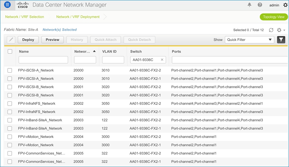
VXLAN Fabric – Enabling Connectivity for Applications
The applications hosted on the FlexPod virtual server infrastructure require connectivity through the VXLAN fabric – this is provided by the networks in the FPV-Application_VRF tenant. The following Application networks were enabled in the VXLAN fabric for validating this design.
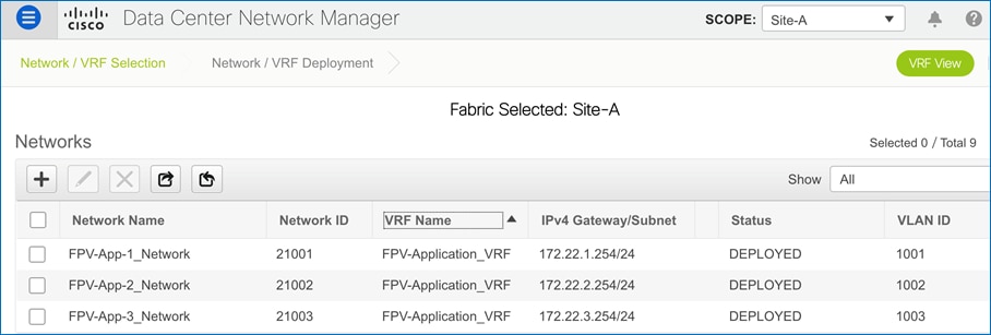
These networks are enabled on the vPC providing access layer connectivity to Cisco UCS where the application VMs that use these networks are running.
Compute & Storage Design Considerations
SAN Boot
NetApp recommends implementing SAN boot for Cisco UCS Servers in the FlexPod Datacenter solution. Implementing SAN boot enables the operating system to be safely secured by the NetApp AFF storage system, providing better performance and flexibility. In this design, iSCSI SAN boot is validated.
In iSCSI SAN boot, each Cisco UCS Server is assigned two iSCSI vNICs (one for each SAN fabric) that provide redundant connectivity all the way to the storage. The 40Gb Ethernet storage ports, in this example e2a and e2e, which are connected to the Nexus switches are grouped to form one logical port called an interface group (ifgroup) (in this example, a0a). The iSCSI virtual LANs (VLANs) are created on the ifgroup and the iSCSI LIFs are created on the iSCSI VLAN ports (in this example, a0a-<iSCSI-A-VLAN>). The iSCSI boot LUN is exposed to the servers through the iSCSI LIF by using igroups. This feature enables only the authorized server to have access to the boot LUN. See Figure 18 for the port and LIF layout.
Figure 18. iSCSI - SVM Ports and LIF Layout
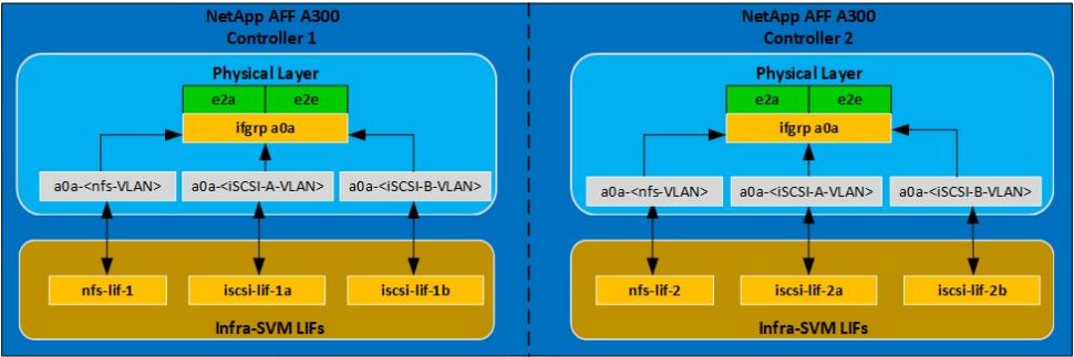
Unlike NAS network interfaces, the SAN network interfaces are not configured to fail over during a failure. Instead if a network interface becomes unavailable, the host chooses a new optimized path to an available network interface by communicating with the storage controllers via Asymmetric Logical Unit Access (ALUA). The ALUA protocol is an industry standard protocol supported by NetApp that is used to provide information about SCSI targets. This information enables a host to identify the optimal path to the storage.
iSCSI and NFS: Network and Storage Connectivity
In the iSCSI design, the storage controller 40GbE ports are directly connected to Cisco Nexus 9336C-FX2 Leaf switches. Each controller is equipped with 40GbE cards in expansion bay 5 that have two physical ports. Each storage controller is connected to two SAN fabrics. This method provides increased redundancy to make sure that the paths from the host to its storage LUNs are always available. Figure 19 shows the port and interface assignment connection diagram for the AFF storage to the Cisco Nexus 9336C-FX2 switches in the VXLAN fabric. This FlexPod design uses the following port and interface assignments. In this design, NFS and iSCSI traffic uses the 40GbE bandwidth.
Figure 19. iSCSI Connectivity
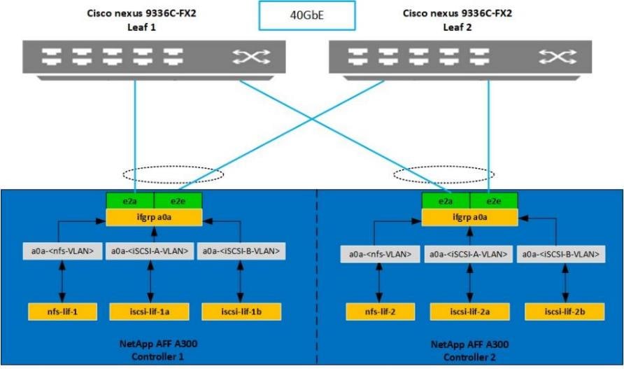
In FlexPod, server networking generally uses the Cisco Virtual Interface Card (VIC). Other networking options are available and supported (https://www.cisco.com/c/en/us/products/interfaces-modules/unified-computing-system-adapters/index.html), but only Cisco 4th Generation VIC (1400 series) will be addressed in this section.
For Cisco UCS B-Series server networking with the Cisco UCS 6400 Series FI, the current IOM choices are the Cisco UCS 2408 Fabric Extender and the Cisco UCS 2204 and 2208 IOMs. The Cisco UCS 2408 provides up to eight 25 GE links on each fabric to the 10/25GE ports on the Cisco UCS 6400 Series FI, while the Cisco UCS 2204 and 2208 provide 10GE links. With the Cisco UCS VIC 1440 and 2408 Fabric Extender, the Port Expander card is now supported. Figure 20 shows Cisco UCS chassis connectivity of a Cisco UCS B200 M5 server with the Cisco UCS VIC 1440 and Port Expander. The Cisco UCS VIC 1440 is in the MLOM slot and the Port Expander is in the Mezzanine slot. Two 10GE KR lanes connect between each Cisco UCS 2408 IOM and the MLOM slot. Two more 10GE KR lanes connect between each 2408 IOM and the Mezzanine slot. The Port Expander connects these two additional KR lanes from each IOM to the Cisco UCS VIC 1440. This combination of components along with timing of the KR lanes provides true 40GE vNICs/vHBAs, but individual network flows or TCP sessions on these vNICs have a maximum speed of 25Gbps since 25Gbps links are used in the port channel between the Cisco UCS 2408 IOM and the FI. Multiple flows can provide an aggregate speed of 40Gbps to each IOM or 80Gbps to the server. The Cisco UCS 2408 Fabric Extender can provide up to 200 Gbps from the servers in the chassis to each Cisco UCS 6400 Series FI.
Figure 20. Cisco UCS Chassis Connectivity – Cisco UCS VIC 1440 and Port Expander with Cisco UCS 2408 IOM
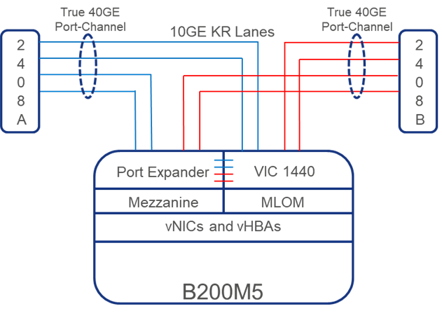
Figure 21 shows Cisco UCS chassis connectivity of a Cisco UCS B200 M5 server with only the Cisco UCS VIC 1440. The Cisco UCS VIC 1440 is in the MLOM slot. Two 10GE KR lanes connect between each Cisco UCS 2408 or 2208 IOM and the MLOM slot. This combination of components provides 20GE vNICs/vHBAs, but individual network flows or TCP sessions on these vNICs have a maximum speed of 10Gbps. Multiple flows can provide an aggregate speed of 20Gbps to each IOM or 40Gbps to the server. The Cisco UCS 2408 Fabric Extender can provide up to 200 Gbps from the servers in the chassis to each 6400 Series FI. If the Cisco UCS 2204 IOM were used here, the MLOM slot would have one KR lane instead of 2, and the vNICs/vHBAs would be 10GE with a total of 20Gbps to the server.
Figure 21. Cisco UCS Chassis Connectivity – Cisco UCS VIC 1440 only with Cisco UCS 2408 IOM
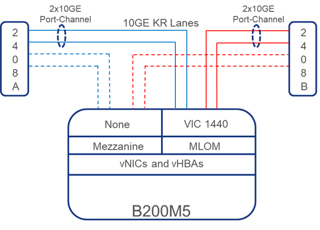
Figure 22 shows another option in Cisco UCS Chassis connectivity to a Cisco UCS B-Series server with Cisco UCS 6400 Series FIs along with the Cisco UCS 2408 IOM and the Cisco UCS VIC 1440 plus Cisco UCS VIC1480. This combination of components provides 20GE (2x10GE) vNICs, but they can be spread across the two network cards and have two sets of physical network connections. Individual network flows or TCP sessions on these vNICs have a maximum speed of 10Gbps, but multiple flows can provide an aggregate speed of 40Gbps to each IOM or 80Gbps to the server. If the Cisco UCS 2208 IOM were used here the vNICs and flow limit would be the same, but the Cisco UCS 2208 has up to 8 10GE links to the fabric interconnect where the Cisco UCS 2408 has up to 8 25GE links. If the Cisco UCS 2204 IOM were used here, each server slot (MLOM and Mezzanine) would have one KR lane instead of 2, and the vNICs/vHBAs would be 10GE with a total of 40Gbps to the server.
Figure 22. Cisco UCS Chassis Connectivity – Cisco UCS VIC 1440 plus Cisco UCS VIC 1480 with Cisco UCS 2408 IOM
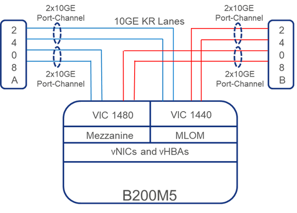
Cisco UCS VIC 1455 and Cisco UCS VIC 1457 are supported with Cisco UCS C-Series servers directly connected to the Cisco UCS 6400 Series FIs. These VICs each have four 10/25GE interfaces with up to two connecting to each fabric interconnect. The connections from the fabric interconnects to the VIC are either single link or dual link port channels. If 25GE interfaces on all four links are used, vNICs/vHBAs are 50Gbps, with an aggregate of 100Gbps to each server. Individual network flows or TCP sessions on these vNICs have a maximum speed of 25Gbps.
![]() When using Cisco UCS VIC 1455 and Cisco UCS VIC 1457 with Cisco UCS 6300 fabric interconnects, only single link port channels, or one 10GE connection to each fabric interconnect is supported.
When using Cisco UCS VIC 1455 and Cisco UCS VIC 1457 with Cisco UCS 6300 fabric interconnects, only single link port channels, or one 10GE connection to each fabric interconnect is supported.
Cisco VIC Virtual Network Interface Card (vNIC) Ethernet Adapter Policy
The Ethernet adapter policy governs the host-side behavior of the vNIC, including how the adapter handles traffic. For example, you can use these policies to change default settings for queues, interrupt handling, performance enhancement, receive side scaling (RSS) hash. Cisco UCS provides a default set of Ethernet adapter policies. These policies include the recommended settings for each supported server operating system. Operating systems are sensitive to the settings in these policies.
A custom VMware-HighTrf Ethernet adapter policy was configured for this implementation according to the section “Configuring an Ethernet Adapter Policy to Enable eNIC Support for RSS on VMware ESXi” in the Cisco UCS Manager Network Management Guide, Release 4.1. This policy is designed to provide higher performance on vNICs with a large number of TCP sessions by providing multiple receive queues serviced by multiple CPUs.
Figure 23. VMware-HighTrf Ethernet Adapter Policy
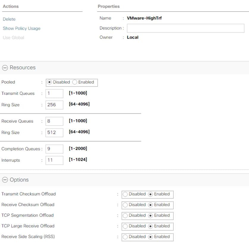
ESXi Host vNIC Layout
FlexPod uses a VMware Virtual Distributed Switch (vDS) for primary virtual switching with additional with six vNICs are defined, two for vSwitch0, two for vDS0, and two for the iSCSI uplinks. vSwitch0 is defined during VMware ESXi host configuration and contains the FlexPod infrastructure management VLAN, and the FlexPod infrastructure NFS VLAN. The ESXi host VMkernel (VMK) ports for management, and infrastructure NFS are placed on vSwitch0. An infrastructure management virtual machine port group is also placed on vSwitch0 and the vCenter virtual machine’s management interface is placed here. vCenter is placed on vSwitch0 instead of the vDS because if the FlexPod infrastructure is shut down or power cycled and vCenter is attempted to be brought up on a host other than the host on which it was originally running, it will boot up fine on the network on vSwitch0. If vCenter were on the vDS and moved to another host then booted, it would not be connected to the network after booting up.
The vDS can contain port groups for tenant iSCSI and NFS VMKs and VMs (for in-guest iSCSI and NFS), tenant management and virtual machine (VM) networks, and the vMotion VMKs. Previous versions of this design also included the infrastructure management VM network on the vDS, but that is left only on vSwitch0 in this design to provide simplicity in the design. The vDS uplinks also have the VMware-HighTrf UCS Ethernet Adapter Policy, providing more queuing and throughput on the adapters.
Placing the vMotion VMK on the vDS allows QoS to be applied to vMotion if necessary, in the future. vMotion is also pinned to the switching fabric B uplink with the fabric A uplink as standby using the port group’s Teaming and Failover policy to ensure that vMotion is normally only switched in the fabric B FI. A final note with vMotion is that if a server’s vNICs are 40 Gbps or greater, 3 vMotion VMKs in the same subnet can be provisioned on the server to allow vMotion to establish multiple sessions and take advantage of the higher bandwidth. Infrastructure NFS can optionally be placed on the vDS for higher performance but can be left on vSwitch0 for administrative simplicity. The VMware-HighTrf UCS Ethernet Adapter Policy can also be assigned to the vSwitch0 vNICs for higher performance from vSwitch0. Tenant iSCSI port groups should be pinned to the appropriate switching fabric uplink with the other fabric uplink set as unused. Within the vDS, as additional tenants are added, port groups can be added as necessary. The corresponding VLANs will also need to be added in Cisco UCS Manager and to the vDS vNIC templates. On both vSwitch0 and the vDS, all port groups initially use the Route based on originating virtual port hashing method. If multiple ports in the same port group are configured on a VM, or for better VMK distribution, consider using the Route based on source MAC hash method. Do not use the Route based on IP hash method since that method requires port channeling configuration on the connected switch ports.
Additional tenant vDSs can be deployed with dedicated vNIC uplinks, allowing for RBAC of the visibility and/or adjustment of the vDS to the respective tenant manager in vCenter. Tenant networks do not have a requirement to exist in separate vDSs and can optionally be pulled into the design shown above that was used in the validation of this FlexPod release.
Two iSCSI boot vSwitches are included in Figure 24. Cisco UCS iSCSI boot requires separate vNICs for iSCSI boot. These vNICs use the appropriate fabric’s iSCSI VLAN as the native VLAN and are attached to the appropriate iSCSI boot vSwitch as shown. Optionally, an iSCSI boot vDS can also be added and used or iSCSI can be migrated to port groups with assigned VLANs on vDS0.
Figure 24. vNIC Design with iSCSI Boot
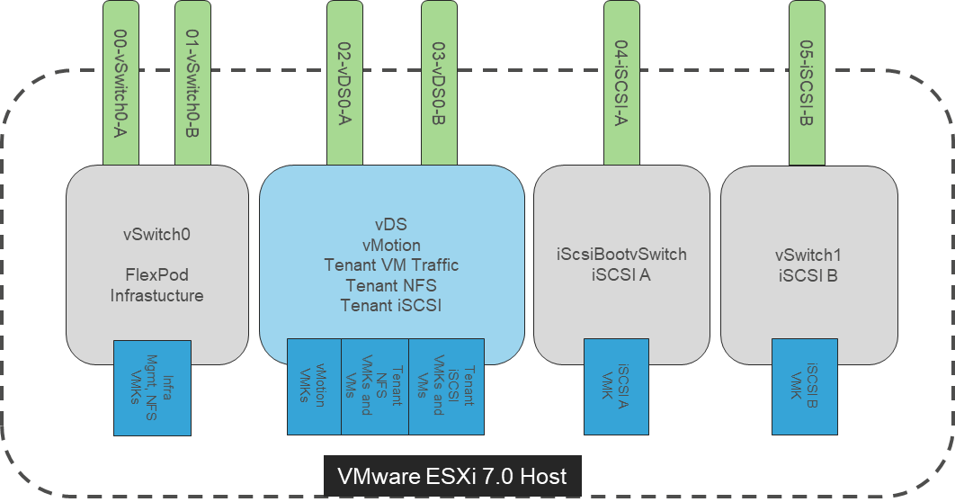
End-to-End IP Network Connectivity
The Cisco Nexus 9000 is the key component bringing together the port-channeled 40/100Gbps capabilities of the other pieces of this design. vPCs extend to both the AFF A300 Controllers and the Cisco UCS 6454 Fabric Interconnects. Passage of this traffic shown in Figure 25 from left to right is as follows:
● Coming from the Cisco UCS B200 M5 server, equipped with a Cisco UCS VIC 1440 adapter and port expander, allowing for 40Gb on each side of the fabric (A/B) into the server.
● Pathing through timed 10Gb KR lanes of the Cisco UCS 5108 Chassis backplane into the Cisco UCS 2408 IOM (Fabric Extender).
● Connecting from each IOM to the Fabric Interconnect with up to eight 25Gb links automatically configured as port channels during chassis association.
● Continuing from the Cisco UCS 6454 Fabric Interconnects into the Cisco Nexus 9336C-FX2 with a bundle of 40/100 ports presenting each side of the fabric from the Nexus pair as a common switch using a vPC.
● Ending at the AFF A300 Controllers with 40Gb bundled vPCs from the Nexus switches now carrying both sides of the fabric.
● Although a given flow is limited to 25 Gbps due to the IOM uplinks and port connections of the 1455/1457, multiple flows can exhaust the greater available bandwidth going across the port channels of the network fabric.
Figure 25. vPC, AFF A300 Controllers, and Cisco UCS 6454 Fabric Interconnect Traffic
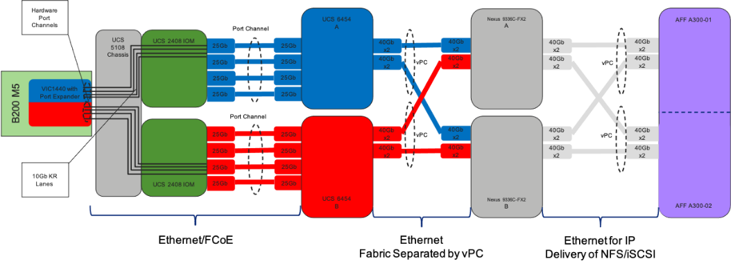
The equivalent view for a Cisco UCS C-Series server is shown in Figure 26. The main difference is that the two 25Gbps interfaces are connected directly between the Cisco UCS VIC 1455/1457 and the FI and are port-channeled into a 50Gbps interface. In this case, a given flow is limited to 25 Gbps:
Figure 26. Cisco UCS C-Series Server
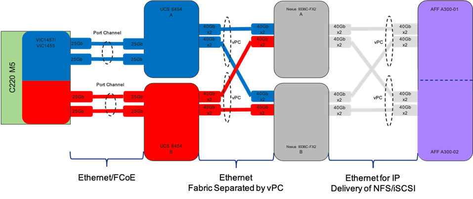
![]() Figures 25 and Figure 26 shows connectivity options that exceed what was used during validation but stand as an example for what can be deployed, with options exceeding the pictured examples depending on port and adapter availability. For reference of the link counts used during the lab validation, please refer to the Physical Topology diagram at the start of the Solution Design section.
Figures 25 and Figure 26 shows connectivity options that exceed what was used during validation but stand as an example for what can be deployed, with options exceeding the pictured examples depending on port and adapter availability. For reference of the link counts used during the lab validation, please refer to the Physical Topology diagram at the start of the Solution Design section.
UEFI Secure Boot
This validation of FlexPod includes usage of UEFI Secure Boot for the first time. Unified Extensible Firmware Interface (UEFI) is a specification that defines a software interface between an operating system and platform firmware. Cisco UCS Manager uses UEFI to replace the BIOS firmware interfaces. This allows the BIOS to run in UEFI mode while still providing legacy support. When UEFI secure boot is enabled, all executables, such as boot loaders and adapter drivers, are authenticated by the BIOS before they can be loaded. Additionally, in this validation Trusted Platform Modules (TPMs) 2.0 were installed in the Cisco UCS B200 M5 and Cisco UCS C220 M5 servers used. VMware ESXi 7.0 supports UEFI Secure Boot. VMware vCenter 7.0 supports UEFI Secure Boot Attestation between the TPM 2.0 module and ESXi, validating that UEFI Secure Boot has properly taken place. The Cisco UCS C125 M5 only supports UEFI boot, iSCSI UEFI Secure Boot is now supported on all platforms.
A high-level summary of the FlexPod Datacenter Design validation is provided in this section. The solution was validated for basic data forwarding by deploying virtual machines running Vdbench. The system was validated for resiliency by failing various aspects of the system under load. Examples of the types of tests executed include:
● Failure and recovery of iSCSI booted ESXi hosts in a cluster
● Rebooting of iSCSI booted hosts
● Service Profile migration between blades
● Failure of partial and complete IOM links
● Failure and recovery of iSCSI paths to AFF nodes, Cisco Nexus switches, and fabric interconnects
● Storage link failure between one of the AFF nodes and the Cisco Nexus
● Load was generated using Vdbench and different IO profiles were used to reflect the different profiles that are seen in customer networks
Validated Hardware and Software
Table 1 lists the hardware and software versions used during solution validation. It is important to note that Cisco, NetApp, and VMware have interoperability matrixes that should be referenced to determine support for any specific implementation of FlexPod. Click the following links for more information:
● NetApp Interoperability Matrix Tool: https://support.netapp.com/matrix/
● Cisco UCS Hardware and Software Interoperability Tool: https://www.cisco.com/web/techdoc/ucs/interoperability/matrix/matrix.html
● VMware Compatibility Guide: https://www.vmware.com/resources/compatibility/search.php
Table 1. Validated Software Revisions
| Layer |
Device |
Image |
Comments |
| Compute |
Cisco UCS Fabric Interconnects 6454, UCS 2408 Fabric Extenders, UCS B-200 M5, UCS C-220 M5, UCS C125 M5 |
4.1(2a) |
Includes the Cisco UCS-IOM 2408, Cisco UCS Manager, Cisco UCS VIC 1440, and Cisco UCS VIC 1457/1455 |
| Network |
Cisco Nexus 9364C NX-OS |
9.3(5) |
Spine Switches |
|
|
Cisco Nexus 9336C-FX2 NX-OS |
9.3(5) |
Leaf Switches |
| Storage |
NetApp AFF A300 |
ONTAP 9.7P6 |
|
| Software |
Cisco UCS Manager |
4.1(2a) |
|
|
|
VMware vSphere |
7.0 |
|
|
|
VMware ESXi nenic Ethernet Driver |
1.0.33.0 |
|
|
|
NetApp Virtual Storage Console (VSC) / VASA Provider Appliance |
9.7.1 |
|
|
|
NetApp NFS Plug-in for VMware VAAI |
1.1.2 |
|
|
|
NetApp Active IQ Unified Manager |
9.7P1 |
|
|
|
Cisco DCNM |
11.4(1) |
VXLAN Fabric Management |
FlexPod Datacenter with VMware vSphere 7.0 and the VXLAN BGP EVPN network design is an optimal shared infrastructure foundation to deploy a variety of IT workloads on a scalable, standards-based network fabric, that is future proofed with 40Gb/s Ethernet connectivity supporting data and storage traffic. Cisco and NetApp have created a platform that is both flexible and scalable for multiple use cases and applications. From virtual desktop infrastructure to SAP®, FlexPod can efficiently and effectively support business-critical applications running simultaneously from the same shared infrastructure. The flexibility and scalability of FlexPod also enables customers to start out with a right-sized infrastructure that can ultimately grow with and adapt to their evolving business requirements.
Cisco Unified Computing System:
https://www.cisco.com/en/US/products/ps10265/index.html
Cisco UCS 6454 Fabric Interconnect:
Cisco UCS 5100 Series Blade Server Chassis:
https://www.cisco.com/en/US/products/ps10279/index.html
Cisco UCS B-Series Blade Servers:
https://www.cisco.com/en/US/partner/products/ps10280/index.html
Cisco UCS C-Series Rack Mount Servers:
Cisco UCS Adapters:
https://www.cisco.com/en/US/products/ps10277/prod_module_series_home.html
Cisco UCS Manager:
https://www.cisco.com/en/US/products/ps10281/index.html
Cisco Nexus 9000 Series Switches:
https://www.cisco.com/c/en/us/products/switches/nexus-9000-series-switches/index.html
Cisco DCNM:
Cisco Intersight:
VMware vCenter Server:
https://www.vmware.com/products/vcenter-server/overview.html
VMware vSphere:
https://www.vmware.com/products/vsphere
NetApp ONTAP 9:
https://www.netapp.com/us/products/platform-os/ontap/index.aspx
NetApp AFF A-Series:
https://www.netapp.com/us/products/storage-systems/all-flash-array/aff-a-series.aspx
NetApp OnCommand:
https://www.netapp.com/us/products/management-software/
NetApp VSC:
https://www.netapp.com/us/products/management-software/vsc/
NetApp NFS Plug-in for VMware VAAI 1.1.2:
https://mysupport.netapp.com/documentation/productlibrary/index.html?productID=61278
NetApp Active IQ:
https://www.netapp.com/services/support/active-iq/
NetApp Active IQ Unified Manager:
https://www.netapp.com/support-and-training/documentation/active-iq-unified-manager/
Cisco Data Center Spine-and-Leaf Architecture: Design Overview White Paper: https://www.cisco.com/c/en/us/products/collateral/switches/nexus-7000-series-switches/white-paper-c11-737022.html
VXLAN Overview: Cisco Nexus 9000 Series Switches: https://www.cisco.com/c/en/us/products/collateral/switches/nexus-9000-series-switches/white-paper-c11-729383.html
Deploy a VXLAN Network with an MP-BGP EVPN Control Plane White Paper:
https://www.cisco.com/c/en/us/products/collateral/switches/nexus-7000-series-switches/white-paper-c11-735015.html
VXLAN: A Framework for Overlaying Virtualized Layer 2 Networks over Layer 3 Networks - IETF RFC 7348: https://tools.ietf.org/html/rfc7348
BGP MPLS-Based Ethernet VPN - IETF RFC 7432:
https://tools.ietf.org/html/rfc7432
Interoperability Matrixes
Cisco UCS Hardware Compatibility Matrix:
https://ucshcltool.cloudapps.cisco.com/public/
VMware and Cisco Unified Computing System:
https://www.vmware.com/resources/compatibility
NetApp Interoperability Matrix Tool:
https://support.netapp.com/matrix/
Ramesh Isaac, Technical Marketing Engineer, Data Center Solutions Engineering, Cisco Systems, Inc.
Ramesh Isaac is a Technical Marketing Engineer in the Cisco UCS Data Center Solutions Group. Ramesh has worked in the data center and mixed-use lab settings since 1995. He started in information technology supporting UNIX environments and focused on designing and implementing multi-tenant virtualization solutions in Cisco labs before entering Technical Marketing where he has supported converged infrastructure and virtual services as part of solution offerings as Cisco. Ramesh has certifications from Cisco, VMware, and Red Hat.
Abhinav Singh, Technical Marketing Engineer, Hybrid Cloud Infrastructures, NetApp
Abhinav is a Technical Marketing Engineer in the Hybrid Cloud Infrastructures Engineering team at NetApp. He has more than 11 years of experience in data center infrastructure solutions which includes On-prem and Hybrid cloud space. He focuses on the validating, supporting, implementing cloud infrastructure solutions that include NetApp products. Prior to joining the Hybrid Cloud Infrastructure Engineering team at NetApp, he was with Cisco Systems as Technical Consulting Engineer working on Cisco Application Centric Infrastructure (ACI). Abhinav holds multiple certifications like Cisco Certified Network Professional (R&S), Double VCP (DCV, NV) and VMware Certified Implementation Expert for Network Virtualization (VCIX-NV). Abhinav holds a bachelor's degree in Electrical & Electronics.
For their support and contribution to the design, validation, and creation of this Cisco Validated Design, the authors would like to thank:
● Archana Sharma, Technical Marketing Engineer, Cisco Systems, Inc.
● John George, Technical Marketing Engineer, Cisco Systems, Inc.
For comments and suggestions about this guide and related guides, join the discussion on Cisco Community at https://cs.co/en-cvds.