FlashStack for Cloud Native with Cisco Intersight, Red Hat OpenShift, and Portworx Enterprise Design
Available Languages
Bias-Free Language
The documentation set for this product strives to use bias-free language. For the purposes of this documentation set, bias-free is defined as language that does not imply discrimination based on age, disability, gender, racial identity, ethnic identity, sexual orientation, socioeconomic status, and intersectionality. Exceptions may be present in the documentation due to language that is hardcoded in the user interfaces of the product software, language used based on RFP documentation, or language that is used by a referenced third-party product. Learn more about how Cisco is using Inclusive Language.
- US/Canada 800-553-2447
- Worldwide Support Phone Numbers
- All Tools
 Feedback
 Feedback

In partnership with:

![]()
About the Cisco Validated Design Program
The Cisco Validated Design (CVD) program consists of systems and solutions designed, tested, and documented to facilitate faster, more reliable, and more predictable customer deployments. For more information, go to: http://www.cisco.com/go/designzone.
Cisco Validated Designs (CVDs) consist of systems and solutions that are designed, tested, and documented to facilitate and improve customer deployments. These designs incorporate a wide range of technologies and products into a portfolio of solutions that have been developed to address the business needs of our customers.
The FlashStack solution is a validated, converged infrastructure developed jointly by Cisco and Pure Storage. The solution offers a predesigned datacenter architecture that incorporates computing, storage, and network design best practices to reduce IT risk by validating the architecture and helping ensure compatibility among the components. The FlashStack solution is successful because of its ability to evolve and incorporate both technology and product innovations in the areas of management, compute, storage, and networking.
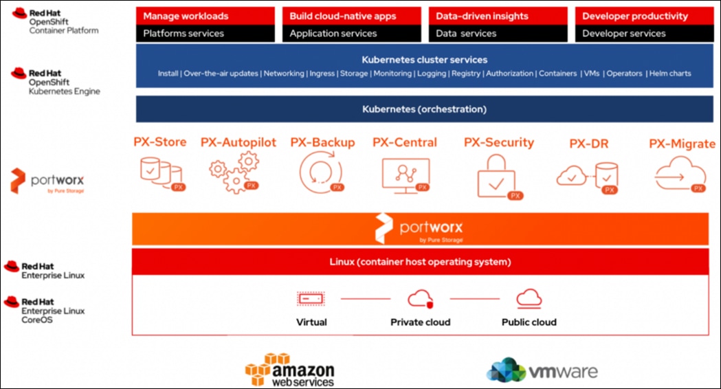
This document explains the design details of Cisco Hybrid Cloud infrastructure solution for containerized workloads using FlashStack Datacenter, Red Hat OpenShift Container Platform (OCP) and Portworx by Pure Storage Enterprise Kubernetes Storage Platform.
The solution presented in this document will address cloud-native hybrid-cloud infrastructure with operational simplicity and ease. A hybrid cloud solution enables enterprises to deploy applications along with data, scaling, backup/restore, replication, asynchronous disaster recovery, Centralized monitoring, metrics, and data management anywhere across a hybrid cloud environment.
On-premises infrastructure is built with FlashStack VSI with the Cisco UCS X-Series modular platform and VMware vSphere 8.0 and is managed using Cisco Intersight. On-premises deployments consist of Red Hat OpenShift Container Platform clusters deployed on VMware vSphere installed on Cisco UCS X210c M6 compute nodes. Red Hat OpenShift Service on AWS (ROSA) managed service is used as cloud clusters. Red Hat Advanced Cluster Management for Kubernetes is used for consistent, centralized Kubernetes management across a hybrid environment. Portworx Enterprise Storage provides cloud native storage for applications running in the cloud, on-prem and in hybrid multi-cloud environments. The Portworx platform also enables services like Kubernetes backup and restore, Asynchronous disaster recovery and auto scaling.
The on-prem infrastructure deployment is automated using Red Hat Ansible to provide Infrastructure as Code (IaC) that can be integrated into existing CI/CD pipelines or other automation to accelerate deployments.
This chapter contains the following:
● Audience
Hybrid cloud has become the de facto deployment and operating model in most Enterprises. In a study conducted by 451 Research across 2500 organizations from around the globe, 82% of the IT decision makers responded that they are already using a hybrid cloud model. Cloud computing from hyper-scalers such as Amazon Web Services (AWS), Microsoft Azure and Google Cloud offer limitless scale and flexibility, but it also comes with increasingly high costs, at times higher risk, leaving Enterprises with less control over their business-critical applications and data. As a result, Enterprises are adopting a hybrid strategy that allows them to optimally use both on-prem and public cloud infrastructure to meet their computing needs.
Hybrid cloud model enables Enterprises to:
● Leverage public cloud for specific use cases, for example, to meet short-term spikes in demand or for disaster recovery (DR). An Enterprise can minimize their CAPEX investment by not having to maintain under-utilized on-prem resources for these scenarios. However, a hybrid cloud DR strategy that requires the movement of data back to the Enterprise could get very costly as cloud providers charge considerably more for moving the data out of the cloud than for moving data into the cloud.
● Benefit from higher availability inherent in the hybrid cloud model. The Enterprise’s datacenter is now distributed across different infrastructures in different geographical locations, one managed by the Enterprise and the other by the cloud provider. As such, in most cases and if designed properly, a failure in one location should only impact that location.
● Accelerate innovation through increased agility as Enterprises can quickly spin up environments in the public cloud to start their development efforts and still have the option to deploy the application on-prem for testing or production where it might be easier to integrate into existing tools and processes. It also allows them to retain control of their data.
● Flexibility to select an optimal infrastructure and location that best meets their business needs. Each organization will have unique costs, compliance, security, performance, and other requirements and it helps to have more options.
Some of the common Enterprise use cases for hybrid cloud are:
● Enabling cloud-native environments anywhere, either on-prem or public cloud, with consistent life cycle management across a hybrid infrastructure environment. Enterprises need this to accelerate their application modernization efforts and for developing new applications. In production, the hybrid model enables them to deploy some applications in the cloud while keeping others on-prem, or host applications in both environments for redundancy, load-balancing etc.
● Development and Test (Dev/Test) where multiple teams in an application’s build/release cycle need multiple infrastructure environments for development, testing, production etc. For example, organizations may start their initial development in the public cloud where they can quickly spin up an environment, but then will deploy that application into production on-prem where they can easily access backend data, tooling, and other resources .
● Backup and recovery where the application resides either on-prem or distributed across both on-prem and cloud, but the data is backed up in the cloud. Recovery in this case can be to on-prem and/or cloud depending on the application.
● Cloud bursting or datacenter extension where an application scales into the cloud to meet peak demands or to enhance the on-prem application using Machine Learning or other data-intensive computations running in the cloud.
The solution presented in this document will address these use cases and deliver a cloud-native hybrid-cloud infrastructure with operational simplicity and ease. It will enable developers and operators to quickly deploy cloud-native workloads anywhere with consistent operational experience across both environments. The solution is built using Cisco X-series modular based FlashStack, Cisco Intersight, Amazon Web Services (AWS), Red Hat OpenShift Container Platform (OCP) and Portworx Enterprise Storage Platform. Portworx storage provider will use FlashArray for backend storage.
Purpose of this Document
This document provides design guidance for a Cisco hybrid cloud infrastructure solution for cloud-native workloads. The document provides the end-to-end design for implementing the solution across a FlashStack Datacenter and public cloud. Hardware and software components used to validate the solution in Cisco’s internal labs are also provided.
The document addresses various considerations and best practices for a successful deployment enabling enterprises to deploy container workloads along with data, scaling, backup and restore, replication, asynchronous disaster recovery, centralized monitoring, metrics, and data management anywhere across a hybrid cloud environment. It also highlights the design and product requirements for integrating virtualization and storage systems with the Cisco Intersight platform to deliver a true cloud-based integrated approach to infrastructure management.
What’s New in this Release?
At a high level, this solution delivers a simple, flexible, and scalable infrastructure for an Enterprise’s cloud-native efforts, enabling workloads along with the data to be deployed anywhere from on-prem to a public cloud. The solution supports the following hybrid cloud use cases:
● Enable cloud-native environments anywhere with consistent management.
● Development and Test
● Backup and recovery
● Auto scaling
● Asynchronous Disaster Recovery (DR)
● Centralized monitoring, metrics, and data management
The following design elements distinguish this version of Cisco’s hybrid cloud from previous models:
● Support for Red Hat OpenShift Container Platform 4.12.
● Control plane and worker nodes deployed on VMware vSphere 8.0 cluster with Cisco UCS X210c M6 Compute Nodes.
● Red Hat OpenShift Service on AWS.
● Portworx Enterprise Storage Platform by Pure Storage for data services deployed on Red Hat OpenShift Container Platform clusters.
● FlashArray//XL170 for backend storage.
● Cisco Intersight cloud operations platform for on-premise infrastructure management:
◦ Integration of the Cisco UCS X-Series modular into FlashStack
◦ Cisco Intersight for consistent, centralized operations across a hybrid environment
◦ Integration of the Cisco Intersight platform with Pure Storage FlashArray for storage monitoring and orchestration.
◦ Integration of the Cisco Intersight software with VMware vCenter for Interaction, monitoring, and orchestration of the virtual environment.
● IaC using Red Hat Ansible for the automated deployment of on-prem compute, storage, and networking.
● Automated Install of Red Hat OCP on FlashStack Virtual Server Infrastructure (VSI) using Assisted Installation.
This solution provides a foundational reference architecture for a hybrid cloud infrastructure solution. The solution enables Enterprises to deploy and develop compute and data intensive cloud-native applications anywhere, with consistent management and operational experience for both developers and IT Operations/Dev-Ops teams.
A hybrid cloud, by definition, is a cloud-computing architecture consisting of at least one on-prem location, a public cloud, and a secure network that interconnects the two locations. This solution delivers a hybrid cloud using a combination of Cisco, Red Hat, Pure Storage and AWS products and technologies as outlined below.
This hybrid cloud infrastructure solution includes a hardware stack from Cisco and Pure Storage, OpenShift Container Platform from Red Hat, hypervisor from VMware and a set of tools for integration and management. These components are integrated so that customers can deploy the solution quickly and economically while eliminating many of the risks associated with researching, designing, building, and deploying similar solutions from the ground up. The products and technologies are outlined below:
● FlashStack Datacenter provide Enterprise-class software-defined compute, storage, and server networking for the on-prem Enterprise datacenter. FlashStack provides a jointly supported solution by Cisco and Pure Storage. Bringing a carefully validated architecture built on superior compute, world class networking, and the leading innovations in all flash storage.
The FlashStack Datacenter for hybrid cloud infrastructure solution offers the following key customer benefits:
◦ Integrated solution that supports the entire Red Hat software-defined stack.
◦ Standardized architecture for quick, repeatable, error-free deployments of FlashStack based workload domains.
◦ Automated life cycle management to keep all the system components up to date.
◦ Simplified cloud-based management of various FlashStack components.
◦ Hybrid-cloud-ready, policy-driven modular design.
◦ Highly available, flexible, and scalable FlashStack architecture.
◦ Cooperative support model and Cisco Solution Support.
◦ Easy to deploy, consume, and manage design that aligns with Cisco, Pure Storage, and Red Hat best practices and compatibility requirements.
◦ Support for component monitoring, solution automation and orchestration, and workload optimization.
● Cisco Intersight provides cloud-based infrastructure management with centralized visibility and operations for all the components of FlashStack datacenter. The SaaS delivery model enables IT teams to benefit from the continuous delivery of innovations and features without having to life cycle manage the management platform. Integration of vCenter, AWS, and OCP nodes in Intersight enables full-stack visibility, monitoring, and resource optimization.
● Red Hat OpenShift Container Platform provides a highly secure, Enterprise-class container orchestration platform with development and operational tools that simplify cloud-native efforts. OCP also delivers a consistent operational experience across both on-prem and public cloud.
● Red Hat Hybrid Cloud Console provides cloud-based centralized management of OCP clusters distributed across on-prem and public clouds in a hybrid deployment. The OCP clusters in the solution, hosted on FlashStack Datacenter and AWS, are deployed from the Red Hat Hybrid Cloud Console.
● Red Hat Advanced Cluster Management for Kubernetes controls clusters and applications from a single console, with built-in security policies. Extend the value of Red Hat OpenShift by deploying apps, managing multiple clusters, and enforcing policies across multiple clusters at scale.
● Red Hat OpenShift Service on AWS (ROSA) is a managed OpenShift service offering on AWS.
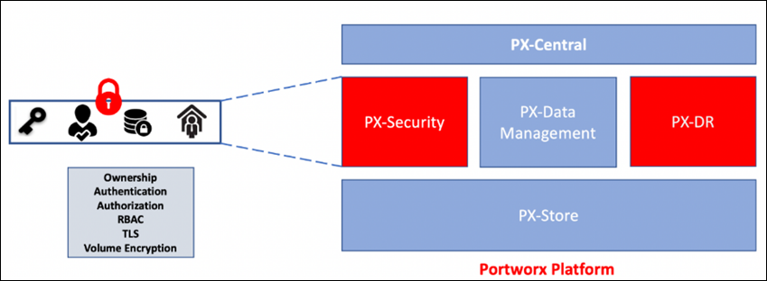
● Portworx Enterprise Kubernetes Storage Platform provides persistent container storage for cloud-native workloads hosted on Cisco X-series compute nodes using the underlying FlashArray storage. It provides other services such as:
◦ PX-Central provides monitoring, metrics, and data management interface for Portworx Enterprise.
◦ PX-Backup delivers enterprise-grade application and data protection with fast recovery.
◦ PX-DR enables asynchronous disaster recovery for the solution.
● VMware vSphere 8.0 provides the virtualization on FlashStack infrastructure. OCP clusters are deployed as VMs on vSphere clusters.
● Infrastructure as Code using Red Hat Ansible automates the deployment of FlashStack infrastructure to speed up deployment and for integration into existing Enterprise automation and/or CI/CD pipelines.
The end-to-end solution was validated in Cisco’s internal labs with Cisco and partner-recommended best practices in place.
This chapter contains the following:
● Cisco Unified Computing System
● Cisco Intersight Assist and Device Connectors
● Cisco Nexus Switching Fabric
● Cisco MDS 9132T 32G Multilayer Fabric Switch
● Red Hat OpenShift Container Platform
● Red Hat Advanced Cluster Management for Kubernetes
● Portworx Enterprise Storage Platform
● Amazon Web Services (AWS) and Red Hat OpenShift Service on AWS
● Infrastructure as Code with Red Hat Ansible
Cisco and Pure Storage have partnered to deliver many Cisco Validated Designs, which use best-in-class storage, server, and network components to serve as the foundation for virtualized workloads, enabling efficient architectural designs that you can deploy quickly and confidently.
FlashStack architecture is built using the following infrastructure components for compute, network, and storage (Figure 1):
● Cisco Unified Computing System (Cisco UCS)
● Cisco Nexus switches
● Cisco MDS 9000 switches
● Pure Storage FlashArray
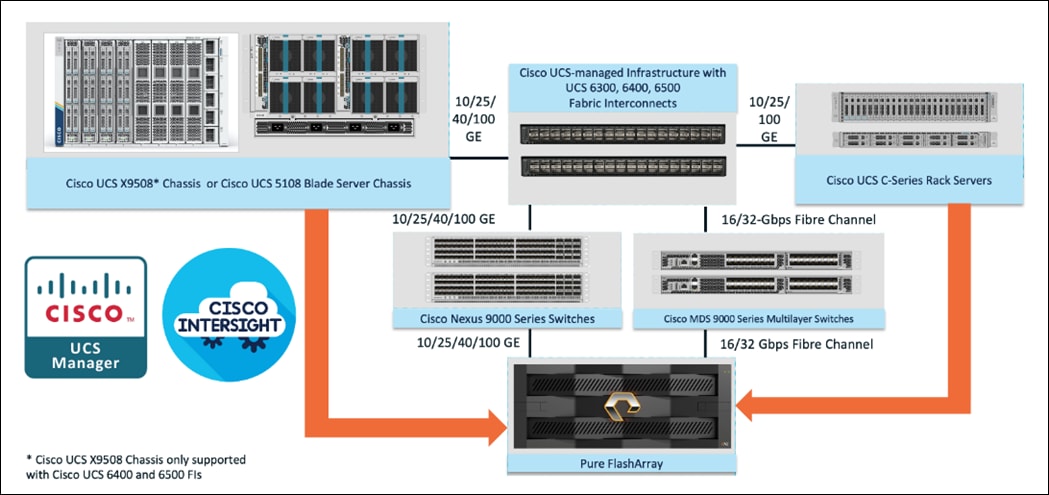
All FlashStack components are integrated, so customers can deploy the solution quickly and economically while eliminating many of the risks associated with researching, designing, building, and deploying similar solutions from the foundation. One of the main benefits of FlashStack is its ability to maintain consistency at scale. Each of the component families shown in Figure 1 (Cisco UCS, Cisco Nexus, Cisco MDS, and Pure Storage FlashArray systems) offers platform and resource options to scale up or scale out the infrastructure while supporting the same features and functions.
The FlashStack solution with Cisco UCS X-Series uses the following hardware components:
● Cisco UCS X9508 chassis with any number of Cisco UCS X210c M6 compute nodes.
● Cisco UCS fourth-generation 6454 fabric interconnects to support 25- and 100-GE connectivity from various components.
● High-speed Cisco NXOS-based Nexus 93180YC-FX3 switching design to support up to 100-GE connectivity.
● Pure Storage FlashArray//XL170 with high-speed Ethernet or Fibre Channel connectivity.
● Pure FlashArray//XL170 storage with 25GbE connectivity to Cisco Nexus switching fabric and 32Gb FC connectivity to Cisco MDS switching fabric.
The software components consist of:
● Cisco Intersight platform to deploy, maintain, and support the FlashStack components.
● Cisco Intersight Assist virtual appliance to help connect the Pure Storage FlashArray and VMware vCenter with the Cisco Intersight platform.
● For virtualized clusters, VMware vCenter 8.0 to set up and manage the virtual infrastructure as well as integration of the virtual environment with Cisco Intersight software.
Cisco Unified Computing System
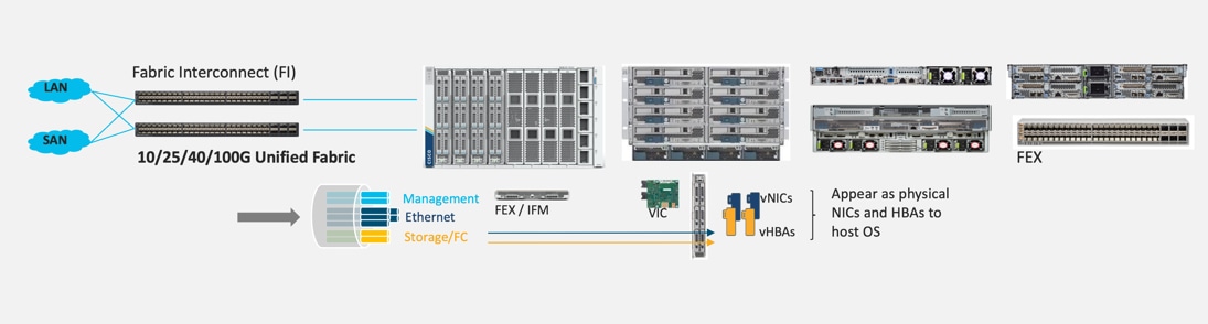
Cisco Unified Computing System (Cisco UCS) is a next-generation datacenter platform that integrates computing, networking, storage access, and virtualization resources into a cohesive system designed to reduce total cost of ownership and increase business agility. The system integrates a low-latency, lossless 10-100 Gigabit Ethernet unified network fabric with enterprise-class, x86-architecture servers. The system is an integrated, scalable, multi-chassis platform with a unified management domain for managing all resources.
Cisco Unified Computing System consists of the following subsystems:
● Compute—The compute piece of the system incorporates servers based on the Second-Generation Intel Xeon Scalable processors. Servers are available in blade and rack form factor, managed by Cisco UCS Manager.
● Network—The integrated network fabric in the system provides a low-latency, lossless, 10/25/40/100 Gbps Ethernet fabric. Networks for LAN, SAN and management access are consolidated within the fabric. The unified fabric uses the innovative Single Connect technology to lower costs by reducing the number of network adapters, switches, and cables. This in turn lowers the power and cooling needs of the system.
● Virtualization—The system unleashes the full potential of virtualization by enhancing the scalability, performance, and operational control of virtual environments. Cisco security, policy enforcement, and diagnostic features are now extended into virtual environments to support evolving business needs.
Cisco Unified Computing System is revolutionizing the way servers are managed in the datacenter. The following are the unique differentiators of Cisco Unified Computing System and Cisco UCS Manager:
● Embedded Management—In Cisco UCS, the servers are managed by the embedded firmware in the Fabric Inter-connects, eliminating the need for any external physical or virtual devices to manage the servers.
● Unified Fabric—In Cisco UCS, from blade server chassis or rack servers to FI, there is a single Ethernet cable used for LAN, SAN, and management traffic. This converged I/O results in reduced cables, SFPs and adapters – reducing capital and operational expenses of the overall solution.
● Auto Discovery—By simply inserting the blade server in the chassis or connecting the rack server to the fabric interconnect, discovery and inventory of compute resources occurs automatically without any management intervention. The combination of unified fabric and auto-discovery enables the wire-once architecture of Cisco UCS, where compute capability of Cisco UCS can be extended easily while keeping the existing external connectivity to LAN, SAN, and management networks.
Cisco UCS Manager (UCSM) provides unified, integrated management for all software and hardware components in Cisco UCS. Using Cisco Single Connect technology, it manages, controls, and administers multiple chassis for thousands of virtual machines. Administrators use the software to manage the entire Cisco Unified Computing System as a single logical entity through an intuitive graphical user interface (GUI), a command-line interface (CLI), or through a robust application programming interface (API).
Cisco Unified Compute System X-Series
The Cisco UCS X-Series modular system is designed to take the current generation of the Cisco UCS platform to the next level with its design that will support future innovations and management in the cloud (Figure 2). Decoupling and moving platform management to the cloud allows the Cisco UCS platform to respond to features and scalability requirements much faster and more efficiently. Cisco UCS X-Series state-of-the-art hardware simplifies the datacenter design by providing flexible server options. A single server type that supports a broader range of workloads results in fewer datacenter products to manage and maintain. The Cisco Intersight cloud management platform manages the Cisco UCS X-Series as well as integrates with third-party devices. These devices include VMware vCenter and Pure Storage to provide visibility, optimization, and orchestration from a single platform, thereby enhancing agility and deployment consistency.
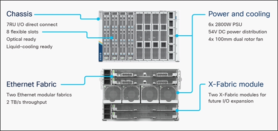
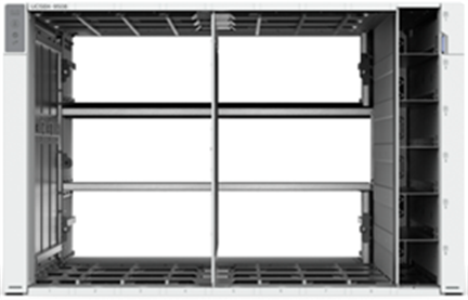
Cisco UCS X9508 Chassis
The Cisco UCS X-Series chassis is engineered to be adaptable and flexible. As seen in Figure 3, Cisco UCS X9508 chassis has only a power-distribution midplane. This innovative design provides fewer obstructions for better airflow. For I/O connectivity, vertically oriented compute nodes intersect with horizontally oriented fabric modules, allowing the chassis to support future fabric innovations. Cisco UCS X9508 Chassis’ superior packaging enables larger compute nodes, thereby providing more space for actual compute components, such as memory, GPU, drives, and accelerators. Improved airflow through the chassis enables support for higher power components, and more space allows for future thermal solutions (such as liquid cooling) without limitations.
The Cisco UCS X9508 7-Rack-Unit (7RU) chassis has eight flexible slots. These slots can house a combination of compute nodes and a pool of future I/O resources that may include GPU accelerators, disk storage, and nonvolatile memory. At the top rear of the chassis are two Intelligent Fabric Modules (IFMs) that connect the chassis to upstream Cisco UCS 6400 Series Fabric Interconnects. At the bottom rear of the chassis are slots ready to house future X-Fabric modules that can flexibly connect the compute nodes with I/O devices. Six 2800W Power Supply Units (PSUs) provide 54V power to the chassis with N, N+1, and N+N redundancy. A higher voltage allows efficient power delivery with less copper and reduced power loss. Efficient, 100mm, dual counter-rotating fans deliver industry-leading airflow and power efficiency, and optimized thermal algorithms enable different cooling modes to best support the customer’s environment.
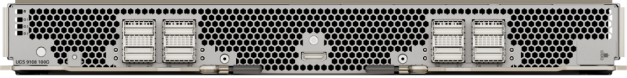
Cisco UCSX 9108-25G Intelligent Fabric Modules
For the Cisco UCS X9508 Chassis, the network connectivity is provided by a pair of Cisco UCSX 9108-25G Intelligent Fabric Modules (IFMs). Like the fabric extenders used in the Cisco UCS 5108 Blade Server Chassis, these modules carry all network traffic to a pair of Cisco UCS 6400 Series Fabric Interconnects (FIs). IFMs also host the Chassis Management Controller (CMC) for chassis management. In contrast to systems with fixed networking components, Cisco UCS X9508s midplane-free design enables easy upgrades to new networking technologies as they emerge making it straightforward to accommodate new network speeds or technologies in the future.

Each IFM supports eight 25Gb uplink ports for connecting the Cisco UCS X9508 Chassis to the FIs and 32 25Gb server ports for the eight compute nodes. IFM server ports can provide up to 200 Gbps of unified fabric connectivity per compute node across the two IFMs. The uplink ports connect the chassis to the Cisco UCS FIs, providing up to 400Gbps connectivity across the two IFMs. The unified fabric carries management, VM, and Fibre Channel over Ethernet (FCoE) traffic to the FIs, where management traffic is routed to the Cisco Intersight cloud operations platform, FCoE traffic is forwarded to the native Fibre Channel interfaces through unified ports on the FI (to Cisco MDS switches), and data Ethernet traffic is forwarded upstream to the datacenter network (via Cisco Nexus switches).
Cisco UCSX 9108-100G Intelligent Fabric Modules
The Cisco UCS 9108-100G and 9108-25G Intelligent Fabric Module (IFM) brings the unified fabric into the blade server enclosure, providing connectivity between the blade servers and the fabric interconnect, simplifying diagnostics, cabling, and management.
This FlashStack solution with Cisco UCS X-Series and 5th Generation Fabric technology uses Cisco UCS 9108 100G IFM.
The Cisco UCS 9108 100G IFM connects the I/O fabric between the 6536 Fabric Interconnect and the Cisco UCS X9508 Chassis, enabling a lossless and deterministic converged fabric to connect all blades and chassis together. Because the fabric module is similar to a distributed line card, it does not perform any switching and is managed as an extension of the fabric interconnects. This approach removes switching from the chassis, reducing overall infrastructure complexity, and enabling Cisco UCS to scale to many chassis without multiplying the number of switches needed, reducing TCO, and allowing all chassis to be managed as a single, highly available management domain. The Cisco UCS 9108 100G IFM also manages the chassis environment (power supply, fans, and blades) in conjunction with the fabric interconnect. Therefore, separate chassis-management modules are not required.
The IFM plugs into the rear side of the Cisco UCS X9508 chassis. The IFM provides a data path from the chassis compute nodes to the Cisco UCS 6536 Fabric Interconnect. Up to two Intelligent Fabric Modules (IFMs) plug into the back of the Cisco UCS X9508 chassis.
The IFMs serve as line cards in the chassis and multiplex data from the compute nodes to the Fabric Interconnect (FI). They also monitor and manage chassis components such as fan units, power supplies, environmental data, LED status panel, and other chassis resources. The server compute node Keyboard-Video-Mouse (KVM) data, Serial over LAN (SoL) data, and Intelligent Platform Management Interface (IPMI) data also travel to the IFMs for monitoring and management purposes. In order to provide redundancy and failover, the IFMs are always used in pairs.
There are 8 x QSFP28 external connectors on an IFM to interface with a Cisco UCS 6536 Fabric Interconnect. The IFM internally provides 1 x 100G or 4 x 25G connections towards each Cisco UCS X210c Compute Node in Cisco X9508 chassis.
Cisco UCS X210c M6 Compute Node
The Cisco UCS X9508 Chassis is designed to host up to 8 Cisco UCS X210c M6 Compute Nodes. The hardware details of the Cisco UCS X210c M6 Compute Nodes are shown in Figure 6:
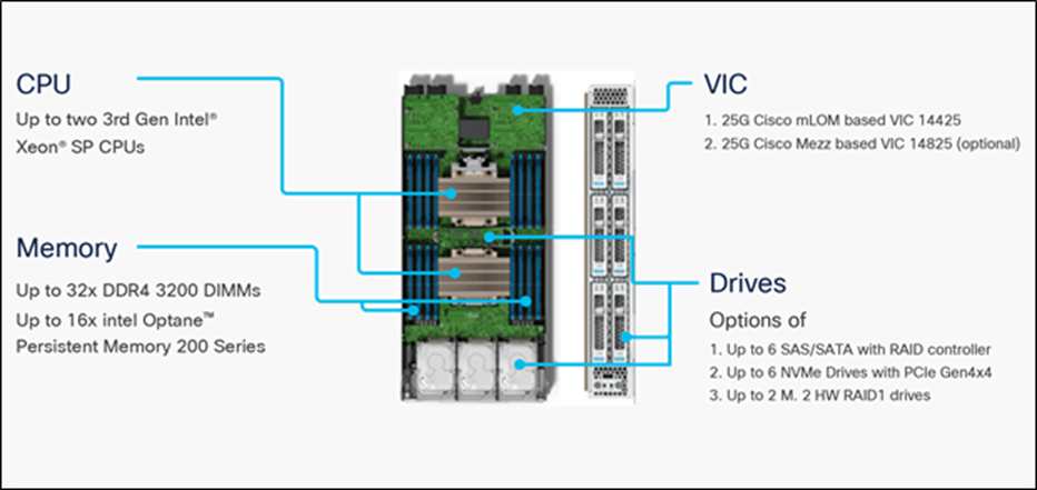
The Cisco UCS X210c M6 features:
● CPU: Up to 2x 3rd Gen Intel Xeon Scalable Processors with up to 40 cores per processor and 1.5 MB Level 3 cache per core.
● Memory: Up to 32 x 256 GB DDR4-3200 DIMMs for a maximum of 8 TB of main memory. The Compute Node can also be configured for up to 16 x 512-GB Intel Optane persistent memory DIMMs for a maximum of 12 TB of memory.
● Disk storage: Up to 6 SAS or SATA drives can be configured with an internal RAID controller, or customers can configure up to 6 NVMe drives. 2 M.2 memory cards can be added to the Compute Node with RAID 1 mirroring.
● Virtual Interface Card (VIC): Up to 2 VICs including an mLOM Cisco VIC 14425 and a mezzanine Cisco VIC card 14825 can be installed in a Compute Node.
● Security: The server supports an optional Trusted Platform Module (TPM). Additional security features include a secure boot FPGA and ACT2 anticounterfeit provisions.
Cisco UCS Virtual Interface Cards (VICs)
Cisco UCS X210c M6 Compute Nodes support the following Cisco fourth-generation VIC cards:
Cisco UCS VIC 14425
Cisco UCS VIC 14425 fits the mLOM slot in the Cisco UCS X210c Compute Node and enables up to 50 Gbps of unified fabric connectivity to each of the chassis IFMs for a total of 100 Gbps of connectivity per server. Cisco UCS VIC 14425 connectivity to the IFM and up to the fabric interconnects is delivered through 4x 25-Gbps connections, which are configured automatically as 2x 50-Gbps port channels. Cisco UCS VIC 14425 supports 256 virtual interfaces (both Fibre Channel and Ethernet) along with the latest networking innovations such as NVMeoF over RDMA (ROCEv2), VxLAN/NVGRE offload, and so on.
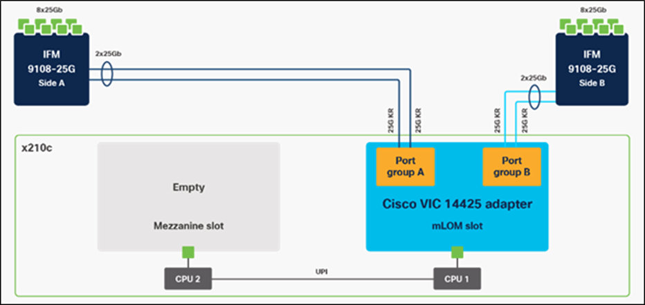
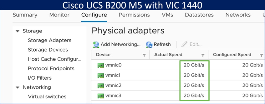
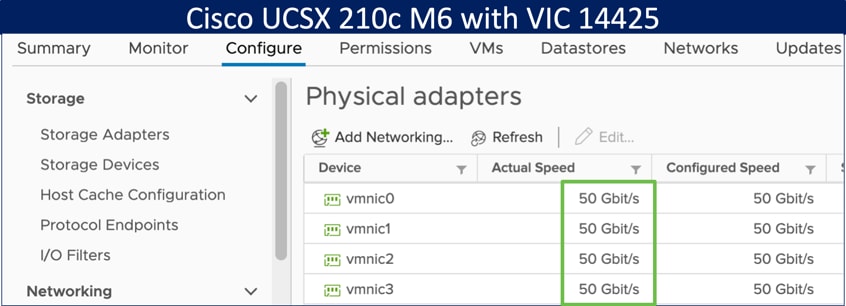
The connections between the 4th generation Cisco UCS VIC 1440 in the Cisco UCS B200 blade servers and the I/O modules in the Cisco UCS 5108 chassis comprise of multiple 10Gbps KR lanes. The same connections between Cisco UCS VIC 14425 and IFMs in Cisco UCS X-Series comprise of multiple 25Gbps KR lanes resulting in 2.5x better connectivity in Cisco UCS X210c M6 Compute Nodes.
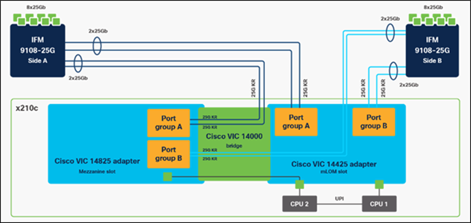
Cisco UCS VIC 14825
The optional Cisco UCS VIC 14825 fits the mezzanine slot on the server. A bridge card (UCSX-V4-BRIDGE) extends this VIC’s 2x 50 Gbps of network connections up to the mLOM slot and out through the mLOM’s IFM connectors, bringing the total bandwidth to 100 Gbps per fabric for a total bandwidth of 200 Gbps per server.
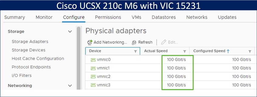
Cisco UCS VIC 15231
Cisco UCS VIC 15231 fits the mLOM slot in the Cisco X210c Compute Node and enables up to 100 Gbps of unified fabric connectivity to each of the chassis IFMs for a total of 200 Gbps of connectivity per server.
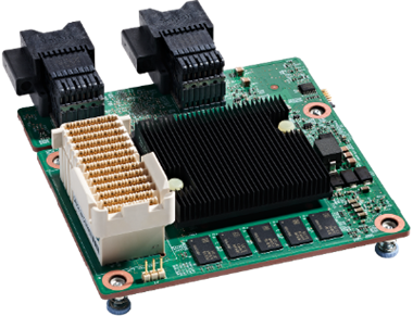
Cisco UCS VIC 15231 connectivity to the IFM and up to the fabric interconnects is delivered through 2x 100-Gbps connections. Cisco UCS VIC 15231 supports 256 virtual interfaces (both Fibre Channel and Ethernet) along with the latest networking innovations such as NVMeoF over RDMA (ROCEv2), VxLAN/NVGRE/GENEVE offload, and so on.
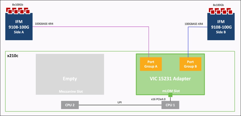
The connections between Cisco UCS VIC 15231 and IFMs in Cisco UCS X-Series results in 2x better connectivity in Cisco UCS X210c M6 Compute Nodes compared to 4th generation Cisco UCS VIC 14425 in the Cisco UCS x210 compute nodes.
The network interface speed comparison between VMware ESXi installed on Cisco UCS B200 M5 with Cisco UCS VIC 1440, Cisco UCS X210c M6 with Cisco UCS VIC 14425 and Cisco UCS X210c M6 with Cisco UCS VIC 15231 are shown in Figure 11.
Cisco UCS Fabric
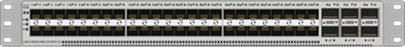
Cisco UCS 6400 Series Fabric Interconnects
The Cisco UCS Fabric Interconnects (FIs) provide a single point of connectivity and management for the entire Cisco UCS system. Typically deployed as an active/active pair, the system’s FIs integrate all components into a single, highly available management domain controlled by the Cisco UCS Manager or Cisco Intersight. Cisco UCS FIs provide a single unified fabric for the system, with low-latency, lossless, cut-through switching that supports LAN, SAN, and management traffic using a single set of cables.
![]()
Cisco UCS 6454 utilized in the current design is a 54-port Fabric Interconnect. This single RU device includes 28 10/25 Gbps Ethernet ports, 4 1/10/25-Gbps Ethernet ports, 6 40/100-Gbps Ethernet uplink ports, and 16 unified ports that can support 10/25 Gigabit Ethernet or 8/16/32-Gbps Fibre Channel, depending on the SFP.
Note: For supporting the Cisco UCS X-Series, the fabric interconnects must be configured in Intersight Managed Mode (IMM). This option replaces the local management with Cisco Intersight cloud or appliance-based management.
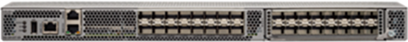
5th Generation Cisco UCS Fabric Interconnects
The Cisco UCS Fabric Interconnects (FIs) provide a single point of connectivity and management for the entire Cisco UCS system. Typically deployed as an active/active pair, the system’s FIs integrate all components into a single, highly available management domain controlled by the Cisco UCS Manager or Cisco Intersight. Cisco UCS FIs provide a single unified fabric for the system, with low-latency, lossless, cut-through switching that supports LAN, SAN, and management traffic using a single set of cables.
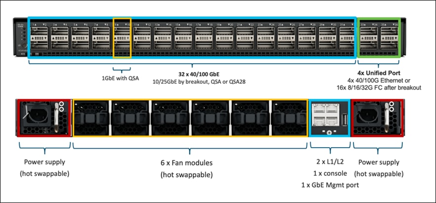
The Cisco UCS 6536 Fabric Interconnect utilized in the current design is a One-Rack-Unit (1RU) 1/10/25/40/100 Gigabit Ethernet, FCoE, and Fibre Channel switch offering up to 7.42 Tbps throughput and up to 36 ports. The switch has 32 40/100-Gbps Ethernet ports and 4 unified ports that can support 40/100-Gbps Ethernet ports or 16 Fiber Channel ports after breakout at 8/16/32-Gbps FC speeds. The 16 FC ports after breakout can operate as an FC uplink or FC storage port. The switch also supports two ports at 1-Gbps speed using QSA, and all 36 ports can breakout for 10- or 25-Gbps Ethernet connectivity. All Ethernet ports can support FCoE.
The Cisco UCS 6536 Fabric Interconnect (FI) is a core part of the Cisco Unified Computing System, providing both network connectivity and management capabilities for the system (Figure 2). The Cisco UCS 6536 Fabric Interconnect offers line-rate, low-latency, lossless 10/25/40/100 Gigabit Ethernet, Fibre Channel, NVMe over Fabric, and Fibre Channel over Ethernet (FCoE) functions.
The Cisco UCS 6536 Fabric Interconnect provides the communication backbone and management connectivity for the Cisco UCS X-Series compute nodes, Cisco UCS X9508 X-series chassis, Cisco UCS B-series blade servers, Cisco UCS 5108 B-series server chassis, and Cisco UCS C-series rack servers. All servers attached to a Cisco UCS 6536 Fabric Interconnect become part of a single, highly available management domain. In addition, by supporting a unified fabric, Cisco UCS 6536 Fabric Interconnect provides both LAN and SAN connectivity for all servers within its domain.
From a networking perspective, the Cisco UCS 6536 uses a cut-through architecture, supporting deterministic, low-latency, line-rate 10/25/40/100 Gigabit Ethernet ports, a switching capacity of 7.42 Tbps per FI and 14.84 Tbps per unified fabric domain, independent of packet size and enabled services. It enables 1600Gbps bandwidth per X9508 chassis with X9108-IFM-100G in addition to enabling end-to-end 100G ethernet and 200G aggregate bandwidth per X210c compute node. With the X9108-IFM-25G and the IOM 2408, it enables 400Gbps bandwidth per chassis per FI domain. The product family supports Cisco low-latency, lossless 10/25/40/100 Gigabit Ethernet unified network fabric capabilities, which increases the reliability, efficiency, and scalability of Ethernet networks. The 6536 Fabric Interconnect supports multiple traffic classes over a lossless Ethernet fabric from the server through the fabric interconnect. Significant TCO savings come from the Unified Fabric optimized server design in which network interface cards (NICs), Host Bus Adapters (HBAs), cables, and switches can be consolidated.
Cisco UCS Unified fabric: I/O consolidation
The Cisco UCS 6536 Fabric Interconnect is built to consolidate LAN and SAN traffic onto a single unified fabric, saving on Capital Expenditures (CapEx) and Operating Expenses (OpEx) associated with multiple parallel networks, different types of adapter cards, switching infrastructure, and cabling within racks. The unified ports allow ports in the fabric interconnect to support direct connections from Cisco UCS to existing native Fibre Channel SANs. The capability to connect to a native Fibre Channel protects existing storage-system investments while dramatically simplifying in-rack cabling.
The Cisco UCS 6536 Fabric Interconnect supports I/O consolidation with end-to-end network virtualization, visibility, and QoS guarantees the following LAN and SAN traffic:
● FC SAN, IP Storage (iSCSI, NFS), NVMEoF (NVMe/FC, NVMe/TCP, NVMe over ROCEv2)
● Server management and LAN traffic
The I/O consolidation under the Cisco UCS 6536 fabric interconnect along with the stateless policy-driven architecture of Cisco UCS and the hardware acceleration of the Cisco UCS Virtual Interface card provides great simplicity, flexibility, resiliency, performance, and TCO savings for the customer’s compute infrastructure.
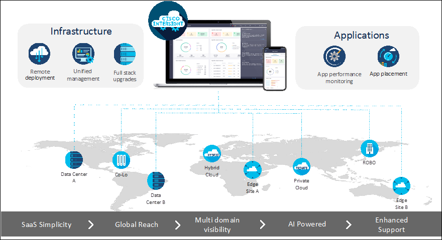
As applications and data become more distributed from core datacenter and edge locations to public clouds, a centralized management platform is essential. IT agility will be struggle without a consolidated view of the infrastructure resources and centralized operations. Cisco Intersight provides a cloud-hosted, management and analytics platform for all Cisco UCS and other supported third-party infrastructure across the globe. It provides an efficient way of deploying, managing, and upgrading infrastructure in the datacenter, ROBO, edge, and co-location environments.
Cisco Intersight provides:
● No Impact Transition: Embedded connector within Cisco UCS will allow customers to start consuming benefits without forklift upgrade.
● SaaS/Subscription Model: SaaS model provides for centralized, cloud-scale management and operations across hundreds of sites around the globe without the administrative overhead of managing the platform.
● Enhanced Support Experience: Hosted platform allows Cisco to address issues platform-wide and experience extends into TAC supported platforms.
● Unified Management: Single pane of glass, consistent operations model, and experience for managing all systems and solutions.
● Programmability: End to end programmability with native API, SDK’s and popular DevOps toolsets will enable customers to consume natively.
● Single point of automation: Automation using Ansible, Terraform and other tools can be done through Intersight for all systems it manages.
● Recommendation Engine: Our approach of visibility, insight and action powered by machine intelligence and analytics provide real-time recommendations with agility and scale. Embedded recommendation platform with insights sourced from across Cisco install base and tailored to each customer.
The main benefits of Cisco Intersight infrastructure services are as follows:
● Simplify daily operations by automating many daily manual tasks.
● Combine the convenience of a SaaS platform with the capability to connect from anywhere and manage infrastructure through a browser or mobile app.
● Stay ahead of problems and accelerate trouble resolution through advanced support capabilities.
● Gain global visibility of infrastructure health and status along with advanced management and support capabilities.
● Upgrade to add workload optimization when needed.
In this solution, Cisco Intersight unifies and simplifies the hybrid cloud operations of FlashStack datacenter components wherever they are deployed.
Cisco Intersight Virtual Appliance and Private Virtual Appliance
In addition to the SaaS deployment model running on Intersight.com, on-premises options can be purchased separately. The Cisco Intersight Virtual Appliance and Cisco Intersight Private Virtual Appliance are available for organizations that have additional data locality or security requirements for managing systems. The Cisco Intersight Virtual Appliance delivers the management features of the Cisco Intersight platform in an easy-to-deploy VMware Open Virtualization Appliance (OVA) or Microsoft Hyper-V Server virtual machine that allows you to control the system details that leave your premises. The Cisco Intersight Private Virtual Appliance is provided in a form factor specifically designed for users who operate in disconnected (air gap) environments. The Private Virtual Appliance requires no connection to public networks or back to Cisco to operate.
Cisco Intersight Assist and Device Connectors
Cisco Intersight Assist helps customers add endpoint devices to Cisco Intersight. A datacenter could have multiple devices that do not connect directly with Cisco Intersight. Any device that is supported by Cisco Intersight but does not connect to Intersight directly needs Cisco Intersight Assist to provide the necessary connectivity. In FlashStack, VMware vCenter and Pure Storage FlashArray connect to Intersight with the help of Intersight Assist appliance.
Cisco Intersight Assist is available within the Cisco Intersight Virtual Appliance, which is distributed as a deployable virtual machine contained within an Open Virtual Appliance (OVA) file format. More details about the Cisco Intersight Assist VM deployment configuration is covered in later sections.
Cisco Intersight integrates with VMware vCenter and Pure Storage FlashArray as follows:
● Cisco Intersight uses the device connector running within Cisco Intersight Assist virtual appliance to communicate with the VMware vCenter.
● Cisco Intersight uses the device connector running within a Cisco Intersight Assist virtual appliance to integrate with to integrate with Pure Storage FlashArray//XL170.
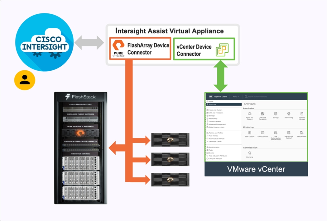
The device connector provides a safe way for connected targets to send information and receive control instructions from the Cisco Intersight portal using a secure Internet connection. The integration brings the full value and simplicity of Cisco Intersight infrastructure management service to VMware hypervisor and FlashArray storage environments. The integration architecture enables FlashStack customers to use new management capabilities with no compromise in their existing VMware or FlashArray operations. IT users will be able to manage heterogeneous infrastructure from a centralized Cisco Intersight portal. At the same time, the IT staff can continue to use VMware vCenter and the Pure Storage dashboard for comprehensive analysis, diagnostics, and reporting of virtual and storage environments. The next section addresses the functions that this integration provides.
The Cisco Nexus 9000 Series Switches offer both modular and fixed 1/10/25/40/100 Gigabit Ethernet switch configurations with scalability up to 60 Tbps of nonblocking performance with less than five-microsecond latency, wire speed VXLAN gateway, bridging, and routing support.
The Cisco Nexus 9000 series switch featured in this design is the Cisco Nexus 93180YC-FX3 configured in NX-OS standalone mode. NX-OS is a purpose-built data-center operating system designed for performance, resiliency, scalability, manageability, and programmability at its foundation. It provides a robust and comprehensive feature set that meets the demanding requirements of virtualization and automation.
The Cisco Nexus 93180YC-FX3 Switch is a 1RU switch that supports 3.6 Tbps of bandwidth and 1.2 bpps. The 48 downlink ports on the 93180YC-FX3 can support 1-, 10-, or 25-Gbps Ethernet, offering deployment flexibility and investment protection. The six uplink ports can be configured as 40- or 100-Gbps Ethernet, offering flexible migration options.
Cisco MDS 9132T 32G Multilayer Fabric Switch
The Cisco MDS 9132T 32G Multilayer Fabric Switch is the next generation of the highly reliable, flexible, and low-cost Cisco MDS 9100 Series switches. It combines high performance with exceptional flexibility and cost effectiveness. This powerful, compact one Rack-Unit (1RU) switch scales from 8 to 32 line-rate 32 Gbps Fibre Channel ports.
The Cisco MDS 9132T delivers advanced storage networking features and functions with ease of management and compatibility with the entire Cisco MDS 9000 family portfolio for reliable end-to-end connectivity. This switch also offers state-of-the-art SAN analytics and telemetry capabilities that have been built into this next-generation hardware platform. This new state-of-the-art technology couples the next-generation port ASIC with a fully dedicated network processing unit designed to complete analytics calculations in real time. The telemetry data extracted from the inspection of the frame headers are calculated on board (within the switch) and, using an industry-leading open format, can be streamed to any analytics-visualization platform. This switch also includes a dedicated 10/100/1000BASE-T telemetry port to maximize data delivery to any telemetry receiver, including Cisco Data Center Network Manager.
Red Hat OpenShift Container Platform
The Red Hat OpenShift Container Platform (OCP) is a container application platform that brings together CRI-0 and Kubernetes and provides an API and web interface to manage these services. CRI-O is a lightweight implementation of the Kubernetes CRI (Container Runtime Interface) to enable using Open Container Initiative (OCI) compatible runtimes including runc, crun, and Kata containers.
OCP allows customers to create and manage containers. Containers are standalone processes that run within their own environment, independent of the operating system and the underlying infrastructure. OCP helps develop, deploy, and manage container-based applications. It provides a self-service platform to create, modify, and deploy applications on demand, thus enabling faster development and release life cycles. OCP has a microservices-based architecture of smaller, decoupled units that work together. It is powered by Kubernetes with data about the objects stored in etcd, a reliable clustered key-value store.
Some of the capabilities in Red Hat OCP include:
● Automated deployment of OCP clusters on-prem (bare metal, VMware vSphere, Red Hat OpenStack Platform, Red Hat Virtualization) and in public clouds.
● Automated upgrades of OCP clusters with seamless over-the-air upgrades initiated from the web console or OpenShift CLI (oc)
● Add services with push-button ease – Once a cluster is deployed, Red Hat OpenShift uses Kubernetes Operators to deploy additional capabilities and services on the cluster. Red Hat Certified and community supported operators are available in the embedded Operator Hub and can be deployed with the click of a button.
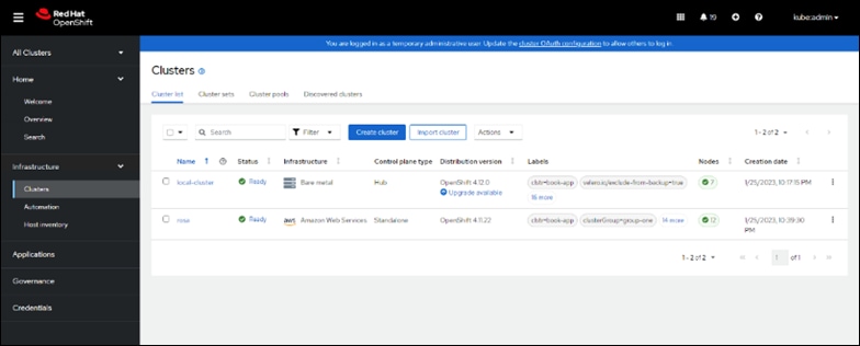
● Multi-cluster management using Red Hat’s cloud-based Hybrid Cloud Console or enterprise-managed Advance Cluster Management (ACM) provides a consolidated view of all clusters, with the ability to easily access and use other K8s technologies and services. OCP clusters can also be individually managed using a web-based cluster console or APIs.
● Persistent storage support – OCP provides support for a broad range of ecosystem storage partners including the Portworx storage used in this solution.
● Scalability – OCP can scale to meet the largest and smallest compute use cases as needed.
● Automate container and application builds, deployments, scaling, cluster management, and more with ease.
● Self-service provisioning – Developers can quickly and easily create applications on demand from the tools they use most, while operations retain full control over the entire environment.
● Source-to-image deployment – OCP provides a toolkit and workflow for producing ready-to-run images by injecting source code into a container and letting the container prepare that source code for execution.
For more information, see: Red Hat OpenShift Container Platform product page on redhat.com.
Kubernetes Infrastructure
Within OpenShift Container Platform, Kubernetes manages containerized applications across a set of CRI-O runtime hosts and provides mechanisms for deployment, maintenance, and application scaling. The CRI-O service packages, instantiates, and runs containerized applications.
A Kubernetes cluster consists of one or more control plane nodes and a set of worker nodes. This solution design includes HA functionality at the hardware as well as the software stack. An OCP cluster is designed to run in HA mode with 3 control plane nodes and a minimum of 2 worker nodes to help ensure that the cluster has no single point of failure.
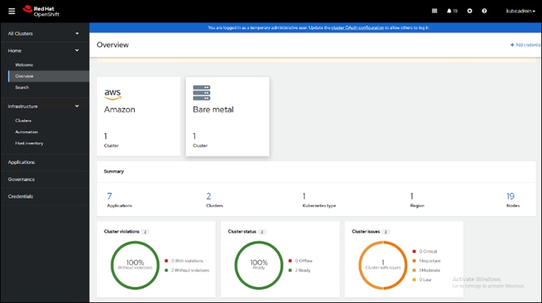
Red Hat Hybrid Cloud Console
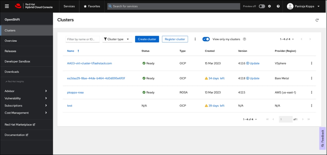
Red Hat Hybrid Cloud Console is a centralized SaaS-based management console for deploying and managing multiple OCP clusters. It is used in this solution to provide consistent container management across a hybrid environment. The SaaS model enables Enterprises to develop, deploy, and innovate faster across multiple infrastructures and quickly take advantage of new capabilities without the overhead of managing the tool. The console gives Enterprises more control and visibility as environments grow and scale. The Hybrid Cloud Console also provides tools to proactively address issues, open and manage support cases, manage cloud costs, subscriptions, and more.
For more information, see: Red Hat Hybrid Cloud Console product page on redhat.com
Consumption Models
Red Hat OpenShift is available as a managed service by Red Hat and major cloud providers or as a self-managed service where the Enterprise manages and maintains the OCP cluster. Red Hat OCP as a managed service is hosted on major public clouds with Red Hat’s expert SRE teams providing a fully managed application platform, enabling the Enterprise to focus on its applications and core business. Red Hat OpenShift is a complete, production-ready application platform with additional services such as CI/CD pipelines, monitoring, security, container registry, service mesh, and more included on top of Kubernetes. Managed cloud-hosted OpenShift services include Red Hat OpenShift Service on AWS, Microsoft Azure Red Hat OpenShift, Red Hat OpenShift Dedicated on Google Cloud or AWS, and Red Hat OpenShift on IBM Cloud.
Installation Options
Red Hat Enterprise Linux CoreOS (RHCOS) is deployed automatically using configurations in the ignition files. The OCP installer creates the Ignition configuration files necessary to deploy the OCP cluster with RHCOS. The configuration is based on the user provided responses to the installer. These files and images are downloaded and installed on the underlying infrastructure by the installer.
● openshift-install is a command line utility for installing openshift in cloud environments and on-prem. It collects information from the user, generates manifests, and uses terraform to provision and configure infrastructure that will compose a cluster.
● Assisted Installer is a cloud-hosted installer available at https://console.redhat.com as both an API and a guided web UI. After defining a cluster, the user downloads a custom “discovery ISO” and boots it on the systems that will be provisioned into a cluster, at which point each system connects to console.redhat.com for coordination. Assisted installer offers great flexibility and customization while ensuring success by running an extensive set of validations prior to installation.
● agent-based installer is a command line utility that delivers the functionality of the Assisted Installer in a stand-alone format that can be run in disconnected and air-gapped environments, creating a cluster without requiring any other running systems besides a container registry.
● Red Hat Advanced Cluster Management for Kubernetes (see the section below) includes the Assisted Installer running on-premises behind a Kubernetes API in addition to a web UI. OpenShift’s bare metal platform features, especially the baremetal-operator, can be combined with the Assisted Installer to create an integrated end-to-end provisioning flow that uses Redfish Virtual Media to automatically boot the discovery ISO on managed systems.
Red Hat Enterprise Linux CoreOS (RHCOS)
RHCOS is a lightweight operating system specifically designed for running containerized workloads. It is based on the secure, enterprise-grade Red Hat Enterprise Linux (RHEL). RHCOS is the default operating system on all Red Hat OCP cluster nodes. RHCOS is tightly controlled, allowing only a few system settings to be modified using the Ignition configuration files. RHCOS is designed to be installed as part of an OCP cluster installation process with minimal user configuration. Once the cluster is deployed, the cluster will fully manage the RHCOS subsystem configuration and upgrades.
RHCOS includes:
● Ignition – for initial bootup configuration and disk related tasks on OCP cluster nodes
Ignition serves as a first boot system configuration utility for initially bringing up and configuring the nodes in the OCP cluster. Starting from a tightly-controlled OS image, the complete configuration of each system is expressed and applied using ignition. It also creates and formats disk partitions, writes files, creates file systems and directories, configures users etc. During a cluster install, the control plane nodes get their configuration file from the temporary bootstrap machine used during install, and the worker nodes get theirs from the control plane nodes. After an OCP cluster is installed, subsequent configuration of nodes is done using the Machine Config Operator to manage and apply ignition.
● CRI-O – Container Engine running on OCP cluster nodes
CRI-O is a stable, standards-based, lightweight container engine for Kubernetes that runs and manages the containers on each node. CRI-O implements the Kubernetes Container Runtime Interface (CRI) for running Open Container Initiative (OCI) compliant runtimes. OCP’s default container runtime is runc. CRI-O has a small footprint and a small attack surface, with an emphasis on security and simplicity. CRI-O is a Cloud Native Computing Foundation (CNCF) incubating project.
● Kubelet – Kubernetes service running on OCP cluster nodes
Kubelet is a Kubernetes service running on every node in the cluster. It communicates with the control plane components and processes requests for running, stopping, and managing container workloads.
● Set of container tools
Container Tools: RHCOS includes a set of container tools (including podman, skopeo, and crictl) for managing containers and container image actions such as start, stop, run, list, remove , build, sign, push, and pull.
● rpm-ostree combines RPM package management with libostree’s immutable content-addressable operating system image management. RHCOS is installed and updated using libostree, guaranteeing that the installed OS is in a known state, with transactional upgrades and support for rollback.
Note: RHCOS was used on all control planes and worker nodes to support the automated OCP 4 deployment.
Red Hat Advanced Cluster Management for Kubernetes (ACM)
Red Hat Advanced Cluster Management for Kubernetes controls clusters and applications from a single console, with built-in security policies. It extends the value of OpenShift by deploying apps, managing multiple clusters, and enforcing policies across multiple clusters at scale. Red Hat’s solution ensures compliance, monitors usage, and maintains consistency.
Running on Red Hat OpenShift, Red Hat Advanced Cluster Management for Kubernetes includes capabilities that unify multi-cluster management, provide policy-based governance, and extend application lifecycle management.
Unified Multi-Cluster Management
● Centrally create, update, and delete Kubernetes clusters across multiple private and public clouds.
● Search, find, and modify any Kubernetes resource across the entire domain.
● Quickly troubleshoot and resolve issues across your federated domain.
● When creating or updating clusters, automate tasks such as configuring cloud-defined storage, static IP addresses, updating network components (like firewalls or load balancers), and more with the integration of Red Hat Ansible Automation Platform.
Policy-based Governance, Risk and Compliance
● Centrally set and enforce policies for security, applications, and infrastructure.
● Quickly visualize detailed auditing on configuration of apps and clusters.
● Immediate visibility into your compliance posture based on your defined standards.
● Automate remediation of policy violations and gather audit information about the clusters for analysis with the integration of Red Hat Ansible Automation Platform.
Advanced Application Lifecycle Management
● Define and deploy applications across clusters based on policy.
● Quickly view service endpoints and pods associated with your application topology—with all the dependencies.
● Automatically deploy applications to specific clusters based on channel and subscription definitions.
● When deploying or updating applications, automate configurations like networking, databases, and more with the integration of Red Hat Ansible Automation Platform.
Multi-cluster Observability for Health and Optimization
● Get an overview of multi-cluster health and optimization using out-of-the-box multi-cluster dashboards with the ability to store long-term data.
● Easily sort, filter, and do a deep scan of individual clusters or, at the aggregated multi-cluster level.
● Get an aggregated view of cluster metrics.
● Troubleshoot faster using the Dynamic Search and Visual Web Terminal capabilities.
Multi-cluster Networking with Submariner
● Provide cross-cluster network infrastructure with Submariner for direct and encrypted communication.
● Use DNS service discovery for Kubernetes clusters connected by Submariner in multi-cluster environments.
● Uniformly manage and observe microservices-based applications network flow for behavioral insight, control, and troubleshooting.
Portworx Enterprise Kubernetes Storage Platform
Portworx Enterprise is the multi cloud ready software defined storage platform for running mission critical applications. Portworx is a fully integrated solution for persistent storage, disaster recovery, data security, cross-cloud data migrations, and automated capacity management for applications.
Portworx provides container optimized storage for applications with no downtime with features like elastic scaling and a high availability solution across nodes/racks/AZs. Portworx is designed to have consistent application performances by storage-aware class-of-service (COS) and application-aware I/O tuning.
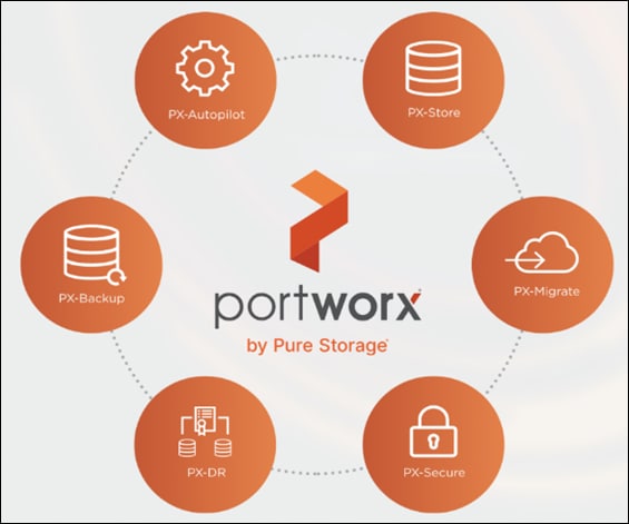
Portworx secures the environment with encryption and access controls, provides cluster-wide encryption with container or storage class based BYOK encryption. Portworx supports Role-based Access Control (RBAC) over both cluster operations and volume operations and integration with active directory and LDAP via OIDC.
For cloud native applications, Portworx allows local, application-consistent/aware snapshots for multi-container applications. Portworx Autopilot (PX-Autopilot) for Capacity Management has the ability to automatically resize individual container volumes or your entire storage pools. Portworx rules- based engine with customization capabilities can optimize apps based on performance requirements. PX-Autopilot can easily integrate with multi clouds like Amazon EBS, Google PD, and Azure Block Storage.
Portworx Backup (PX-Backup) can capture entire applications, including data, application configuration, and Kubernetes objects/Metadata, and move them to any backup location at the click of a button and its point-and-click recovery for any Kubernetes app makes it easy for developers. Portworx Disaster Recovery (PX-DR) has the ability to set DR policies at the container granular level and set multi-site synchronous and asynchronous replication for a near zero RPO DR across a metro area.
This solution explains use cases and features that help administrators deploy and operate a robust Kubernetes stack for their developers.
Use Cases and Features of Portworx Enterprise Kubernetes Storage Platform
PX-Store
● Scalable persistent storage for Kubernetes and provides cloud native storage for applications running in the cloud, on-prem, and in hybrid/multi-cloud environments.
● High Availability across nodes/racks/AZs.
● Multi-writer shared volumes across multiple containers.
● Storage-aware class-of-service (COS) and application aware I/O tuning.
● Aggregated volumes for storage pooling across Hosts and provided volume consistency groups.
● Support for OpenStorage SDK and can be plugged into CSI, Kubernetes, and Docker volumes.
PX-Autopilot
Autopilot is a rule-based engine that responds to changes from a monitoring source. Autopilot allows administrators to specify monitoring conditions along with actions it should take when those conditions occur. Autopilot requires a running Prometheus instance in your cluster.
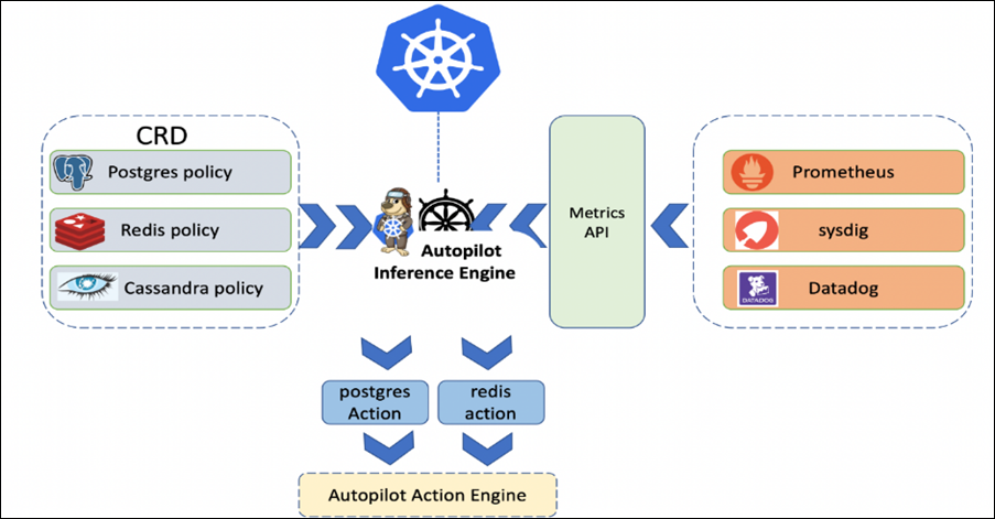
Automatically grow PVCs, expand, and rebalance Portworx storage pool cluster. Portworx APIs are used to expand storage pools across multi-cloud environments like Amazon EBS, Google PD, and Azure Block Storage, VMware vSphere. Scales at the individual volume or entire cluster level and saves money and avoids application outages.
Autopilot monitors the metrics in your cluster (for example, via Prometheus) and once high usage conditions occur, it can resize the PVC.PVC, Namespace selectors, metric conditions are used to resize the action.
AutopilotRule CRD suggests which objects, conditions to monitor, and the corresponding actions to perform. when conditions occur.
An AutopilotRule has the following main parts:
● Selector matches labels on the objects.
● Namespace Selector matches labels on the Kubernetes namespaces.
● Conditions the metrics for the objects to monitor.
● Actions to perform once the metric conditions are met. Action approvals can be done through kubectl or by setting up GitOps and Github.
PX-Backup
Portworx Backup feature allows application level snapshots and can be recovered into any other cluster. PX-backup can be backed up to any public and hybrid cloud location and recovery is as simple as click of a button. Administrators can manage and enforce compliance and governance responsibilities with a single pane of glass for all containerized applications. Enabling application aware backup and fast recovery for even complex distributed applications.
Portworx Backup is capable of backing up the following resources: Persistent Volume (PV), Persistent Volume Claim (PVC), Deployment, StatefulSet, ConfigMap, Service, Secret, DaemonSet, ServiceAccount, Role, RoleBinding, ClusterRole, ClusterRoleBinding and Ingress.
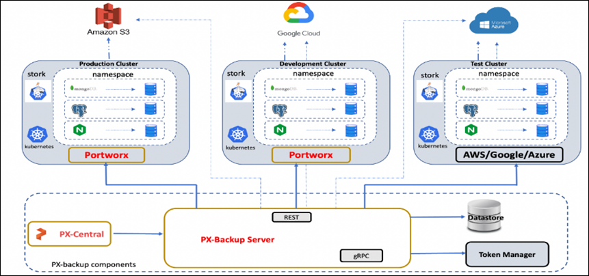
PX-Backup components:
● Portworx Backup server: A gRPC server that implements the basic CRUD operations for objects like Cluster, Backup location, Cloud credential, Schedule policy, Backup, Restore and Backup schedule.
● Application clusters: A cluster in Portworx Backup is any Kubernetes cluster that Portworx Backup makes backups and restores from. It lists all applications and resources available on the cluster. Portworx Backup Server communicates with stork to create application-level backups and it monitors the CRDs on each cluster.
● Datastore: A MongoDB based Database where the Portworx Backup stores objects related to the cluster such as backup location, schedule policies, backup, restore, and backup schedule.
● Token Based Authentication: Communicates with an external service (Okta, KeyCloak, and so on) to validate and authorize tokens that are used for the API calls.
● Backups: Backups in Portworx Backup contain backup images and configuration data.
● Backup locations: A backup location is not tied to any particular cluster and can be used to trigger backups and restores on any cluster. Portworx Backup stores backups on any compatible object storage like AWS S3 or compatible object stores, Azure Blob Storage or Google Cloud Storage.
● Restores: Administrators can restore backups to the original cluster or different clusters, replace applications on the original cluster or restore to a new namespace.
● Schedule Policies: Schedule policies can be created and attached to backups to run them at designated times and designated number of rolling backups.
● Rules: Rules can be used to create commands which run before or after a backup operation is performed.
● Application view: Administrators can interact, create rules, backups with Portworx Backup through a central application view.
PX-Central
Portworx Central on-premises GUI:
● Monitors the clusters using built-in dashboards
● Provides multi-cluster management
● Adds and manages Portworx licenses through the license server
● Views and manages the Portworx volumes and take snapshots.
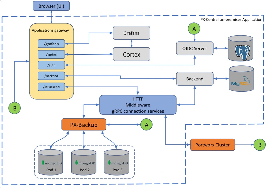
PX-Central Components:
● Application gateway: Uses the Nginx reverse proxy mechanism, where more than one service in the application gateway is exposed on an external network, all these services listen on HTTP or HTTPS.
● OIDC server: Manages the identity of users, groups, and roles of a user. Portworx Central uses KeyCloak (uses postgres as datastore) as a SSO server to enable user authorization.
● Backend service: Laravel PHP based service, manages active users and clusters added on Lighthouse. The backend service provides an option to save states at a user level or global level by making use of a MySQL database.
● Middleware service: A connector service used to interface multiple microservices and third party services to the UI. The middleware passes the token information to the corresponding services, and authorization happens directly at the provider service. The middleware service also provides a common data interface for error or success messages, paginated responses, pagination services and others.
PX-Security
Portworx Security secures the containers with access controls and encryption. It includes cluster wide encryption and BYOK encryption with storage class or container granular based. Role based control for Authorization, Authentication, Ownership and integrates with Active Directory and LDAP.
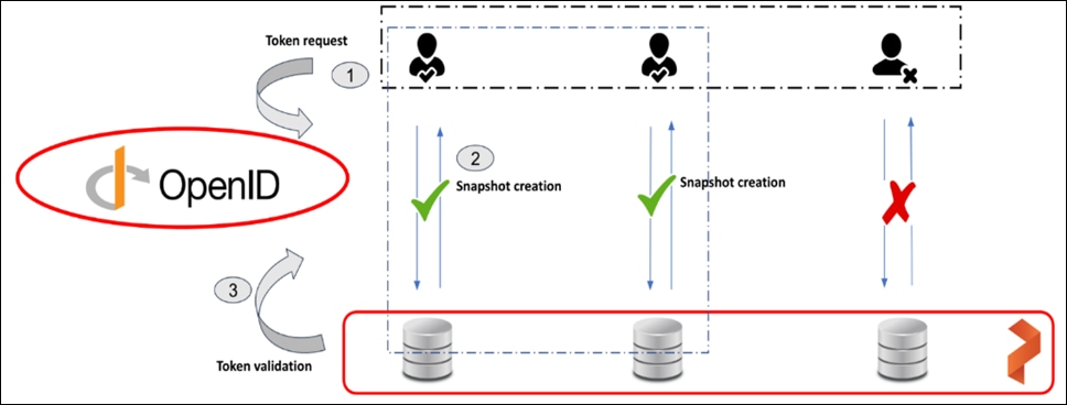
To authenticate users in Portworx, PX-Security supports either OIDC or self-generated tokens. OpenID Connect (or OIDC) is a standard model for user authentication and management and it integrates with SAML 2.0, Active Directory, and/or LDAP. The second model is self-generated token validation. Administrators generate a token using their own token administration application, Portworx provides a method of generating tokens using the Portworx CLI (pxctl).
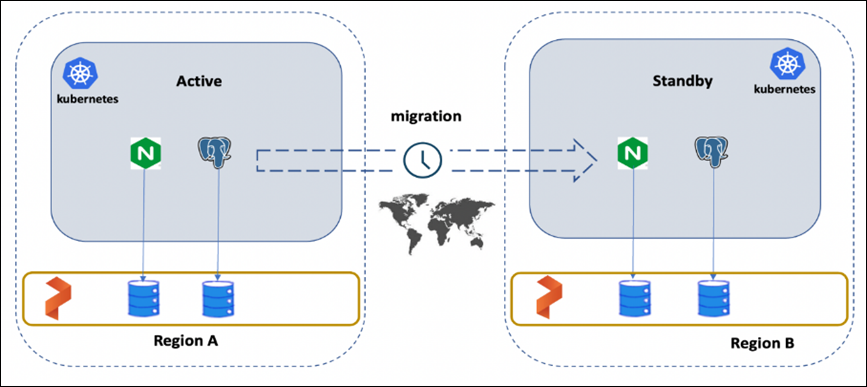
PX-DR
Portworx Disaster Recovery offers a near RPO-zero failover across data centers in a metropolitan area network and in addition to HA within a single datacenter. PX-DR offers continuous incremental-backups and has the ability to set all DP policies at the container granular level.
Portworx provides two primary DR options; Metro DR and asynchronous DR.
● Portworx Metro DR
◦ All the Portworx Nodes in all Kubernetes clusters are in the same Metro Area Network (MAN).
◦ The same cloud region. They can be in different zones.
◦ The same datacenter or data centers that are just 50 miles apart.
◦ The network latency between the nodes is lower than ~10ms.
● Metro DR characteristics
◦ A single Portworx cluster that stretches across multiple Kubernetes clusters.
◦ Portworx installation on all clusters uses a common external key-value store (for example, etcd).
◦ Volumes are automatically replicated across the Kubernetes clusters as they share the same Portworx storage fabric.
◦ This option will have zero RPO and RTO in less than 60 seconds.
◦ witness node is a single virtual machine and a special Portworx storage-less node that participates in quorum but does not store any data.
◦ Metro DR needs a three node etcd cluster for Portworx. One etcd node needs to be running in each data center and one node should be running on the witness node.
● Portworx Asynchronous DR
◦ Nodes in all your Kubernetes clusters are in the different regions or datacenter.
◦ The network latency between the nodes is high.
● Portworx Asynchronous DR characteristics
◦ A separate Portworx cluster installation for each Kubernetes clusters.
◦ Portworx installations on each cluster can use their own key-value store (for example, etcd).
◦ Administrators can create scheduled migrations of applications and volumes between 2 clusters that are paired.
◦ This option will have an RPO of 15 minutes and RTO less than 60 second
PX-Migrate
Portworx migration provides the ability to move or migrate applications between heterogeneous K8s clusters. Apps can be developed in-cloud and can be migrated on-prem or between clusters and a very useful feature during cluster maintenance and upgrades.
● PX-Migrate most used cases
◦ Testing: Administrators can test and validate new versions on the Portworx or the Container cluster versions by seamlessly moving applications across clusters.
◦ Capacity planning: Administrators can free capacity on critical clusters by moving non-critical applications to other secondary clusters.
◦ Development and Testing: Administrators can promote workloads from dev to staging clusters without any disruptions.
◦ Cloud mobility: Move applications and data from an on-prem cluster to a hosted AWS EKS or Google GKE.
◦ Upgrade and Maintenance: Administrators can migrate applications and perform hardware-level upgrades.
● Characteristics of PX-Migrate
◦ Pairing clusters - Establish trust relationship between a pair of clusters.
◦ Administrators can migrate all namespaces or specific namespace from Source to destination clusters.
◦ Migration with Stork on Kubernetes on Kubernetes moves application objects, configuration, data, Kubernetes Objects, Kubernetes Configuration and Portworx volumes.
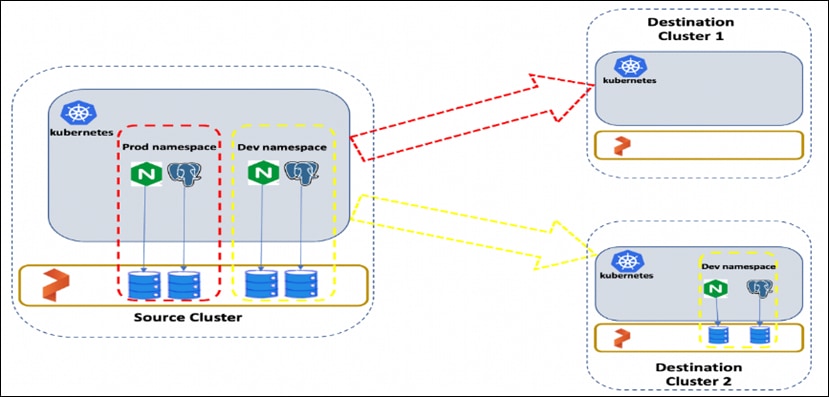
Figure 32 shows the namespace with “dev” is migrated from Source cluster to Destination cluster. Administrators can migrate all namespaces or specific ones.
Portworx STORK
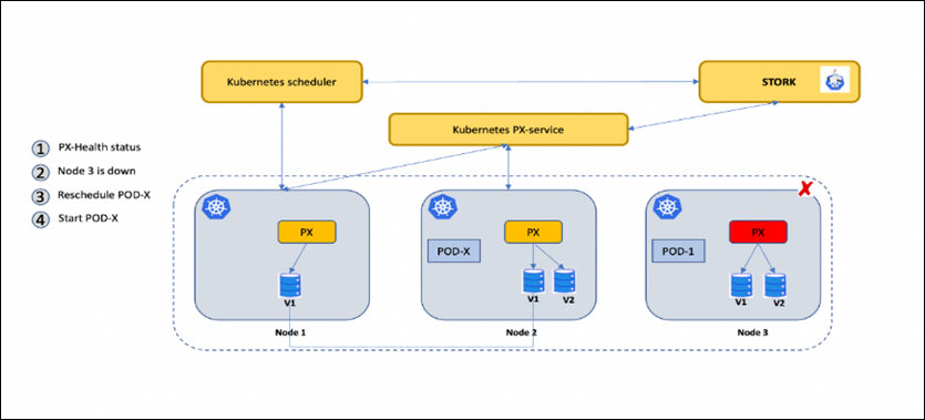
STORK (Storage Orchestrator Runtime for Kubernetes) allows stateful applications to take advantage of scheduler extenders in order to enjoy the benefits of storage-aware scheduling via Kubernetes in production at scale. Using a scheduler extender, STORK provides hyperconvergence, failure-domain awareness, storage health monitoring and snapshot-lifecycle features for stateful applications on Kubernetes.
In Figure 33, you can see how Portworx STORK health monitoring helps to reschedule the PODs to healthy Nodes in the event of a failure. Stork helps in these cases by failing over pods when the storage driver on a node goes into an error or unavailable state and ensures the applications to be truly Highly Available without any user intervention.
Monitoring Portworx Cluster
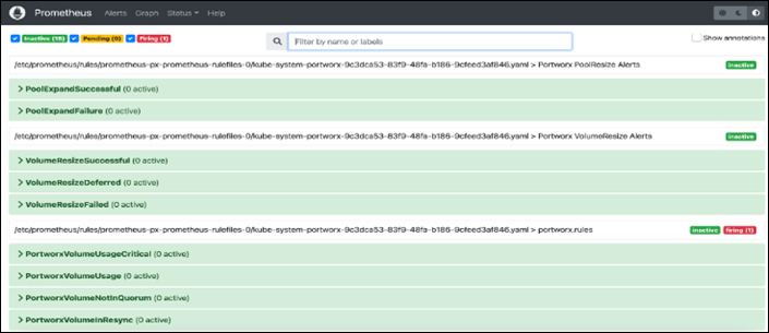
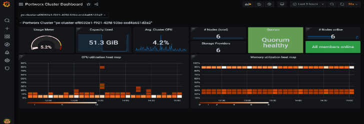
Portworx cluster can be monitored by Prometheus to collect data, Alertmanager to provide notifications and Grafana to visualize your data. Prometheus Alertmanager handles alerts sent from the Prometheus server based on rules you set. You can connect to Prometheus using Grafana to visualize your data. Grafana is a multi-platform open source analytics and interactive visualization web application. It provides charts, graphs, and alerts.
Key highlights of //XL series FlashArray:
● Increased capacity and performance: FlashArray//XL is designed for today’s higher-powered multicore CPUs, which allows FlashArray//XL to increase performance over our FlashArray//X models. Provides more space for fans and airflow, which improves cooling efficiency, and for wider controllers that enable performance to scale today and well into future generations of FlashArray//XL. With greater storage density, FlashArray//XL supports up to 40 DirectFlash Modules in the main chassis.
● Increased connectivity, greater reliability, and improved redundancy: FlashArray//XL doubles the host I/O ports compared to FlashArray//X, for up to 36 ports per controller, and the //XL model provides more expansion slots for configuration flexibility. It doubles the bandwidth for each slot, including full bandwidth for mixed protocols. FlashArray//XL offers multiple 100GbE RDMA over Converged Ethernet (RoCE) links that are very robust to hot-plug and provide faster controller failover speed.
● DirectFlash Modules with distributed NVRAM: DirectFlash Modules include onboard distributed non-volatile random-access memory (DFMD). With DFMD, NVRAM capacity, NVRAM write bandwidth, and array capacity scale with the number of DFMDs, lifting the limit on write throughput.
● DirectCompress Accelerator: Included with every FlashArray//XL shipment, the DirectCompress Accelerator (DCA) increases compression efficiency by offloading inline compression to a dedicated PCIe card. It ensures maximum compression rates, even when the system is under a heavy load, and stretches capacity to reduce overall storage costs and to extend the value of your FlashArray//XL.
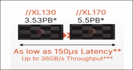
Table 1. FlashArray technical specifications
|
|
Capacity |
Physical |
| //XL170 |
Up to 5.5PB / 5.13PiB effective capacity* |
5-11U; 1850-2355W(nominal-peak) |
| Up to 1.4PB / 1.31PiB raw capacity** |
167lbs (75.7kg) fully loaded;8.72” x 18.94” x 29.72”** |
|
| //XL130 |
Up to 3.53PB / 3.3PiB effective capacity |
5-11U; 1550-2000 watts(nominal-peak) |
| Up to 968TB / 880TiB raw capacity |
167lbs (75.7kg) fully loaded; 8.72” x 18.94” x 29.72 |
|
| DirectFlash Shelf |
Up to 1.9PB effective capacity |
Up to 512TB / 448.2TiB raw capacity |
| 3U; 460-500 watts (nominal–peak) |
87.7lbs (39.8kg) fully loaded; 5.12” x 18.94” x 29.72” |
Table 2. FlashArray Connectivity
| Connectivity |
|
| Onboard Ports
● 2 x 1Gb (RJ45)
|
I/O Expansion Cards (6slots/controller) 2-port 10/25 Gb Ethernet, NVMe/TCP, NVMe/RoCE 2-port 40/100Gb Ethernet, NVMe/TCP, NVMe/RoCE 2-port 16/32/64†Gb FCP, NVMe/FC 4-port 16/32/64 Gb FCP, NVMe/FC |
| Management Ports
● 1 x RJ45 Serial
● 1 x VGA
● 4 x USB 3.0
|
Advantages of using FlashArray as Backend Storage for Portworx Enterprise Storage Platform
Pure Storage FlashArray provides all-flash storage backed by an enterprise-class array with six-nines reliability, data-at-rest encryption, and industry-leading data-reduction technology. Although Portworx supports any storage type including Direct Attached Storage (DAS) and Array based storage, using Portworx replicas to ensure data availability for application pods across nodes, then having all replicas provisioned from the same underlying FlashArray will multiply your standard data-reduction rate, for the application data, by the number of replicas for the persistent volume.
Portworx combined with Pure Storage FlashArray can be used as a cloud storage provider. This allows administrators to store your data on-premises with FlashArray while benefiting from Portworx cloud drive features, automatically provisioning block volumes, Expanding a cluster by adding new drives or expanding existing ones and Support for PX-Backup and Autopilot. Pure Storage FlashArray with Portworx on Kubernetes can attach FlashArray as a Direct Access volume. Used in this way, Portworx directly provisions FlashArray volumes, maps them to a user PVC, and mounts them to pods. FlashArray Direct Access volumes support the CSI operations like filesystem operations. snapshots and QOS.
Container ready infrastructure - Portworx on top of Pure Storage FlashArray to benefit from Kubernetes-native storage and data management. Operate, scale, and secure modern applications and databases on FlashArray and FlashBlade with just a few clicks.
Purity for FlashArray (Purity//FA 6)
Purity is secure, highly scalable, and simple to use, Purity powers all of Pure Storage, including FlashArray//X and FlashArray//XL to deliver comprehensive data services for performance and latency sensitive applications. Purity delivers the industry’s most granular and complete data reduction for unmatched storage efficiency. Purity’s “encrypt everything” approach provides built-in enterprise grade data security without user intervention or key management. Maintain regulatory compliance and help achieve GDPR compliance with FIPS 140-2 validated encryption, and impact-free, AES-256 data-at-rest encryption. Purity ensures business continuity by reducing your risk of downtime while keeping mission-critical applications and data online and accessible. Designed from the ground up for flash, Purity RAID-HA protects against concurrent dual-drive failures and initiates rebuilds automatically within minutes and detects and heals bit-errors. Purity integration with VMware Site Recovery Manager (SRM) lets your automation software orchestrate application recovery and mobility across sites. Purity 6.x delivers additional enhancements, capabilities, and solutions that customers can adopt immediately, non-disruptively, and as part of the Evergreen subscription to innovation.
Pure1
Pure1, the cloud-based as-a-service data-management platform from Pure Storage, raises the bar in what you can expect. Pure1 delivers a single AI-driven hub that’s automated with the Pure1 Meta virtual assistant. You can accomplish common and complex data-management tasks with ease. It’s simple to purchase new or additional services from the service catalog. With Pure1, you can expand anytime, identify problems before they happen, and effortlessly plan for the future.
● Optimize
Pure1 creates a cloud-based storage management tool that’s simple and easy to use without sacrificing enterprise features. With Pure1, you can deliver IT outcomes in seconds vs. hours or days. You can eliminate costly downtime by leveraging predictive analytics and respond to dynamic changes quickly by accessing Pure1 from anywhere in the world.
● Centralized Setup and Monitoring
Setting up Pure1 using the Pure1 portal. As soon as your system is online, Pure1 Meta works in gathering analytics. Live monitoring is available within minutes and accessible from anywhere in the world.
● Full-stack Analysis
Access critical information about the health and functioning of your entire stack, including predictive fault analysis, and alerting.
● Reporting
Pure1 has an intuitive, built-in reporting engine that you can use to generate shareable reports on commonly requested information such as capacity, performance, or even service subscription status.
● Streamline
Elevate your data services experience with Pure1’s built-in AIOps powered by Pure1 Meta. This industry-leading, AI-driven platform for predictive service management ensures a higher level of data availability and performance. You can see all your data service platforms, whether on-premises FlashArray, Cloud Block Store in Azure or Amazon Web Services, or the Portworx container storage platform from one place.
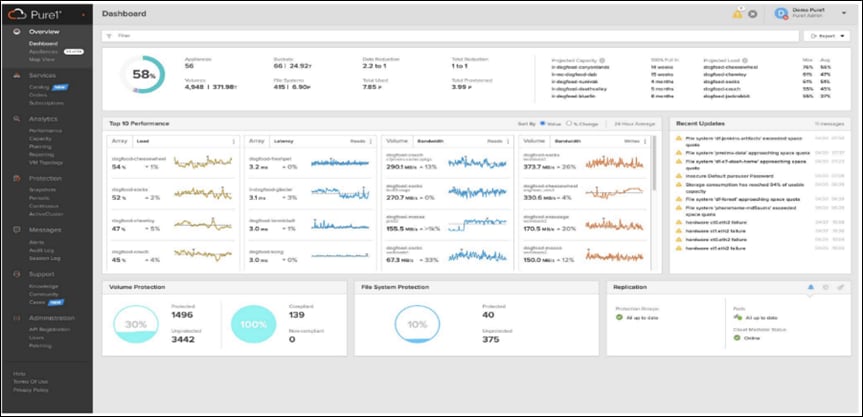
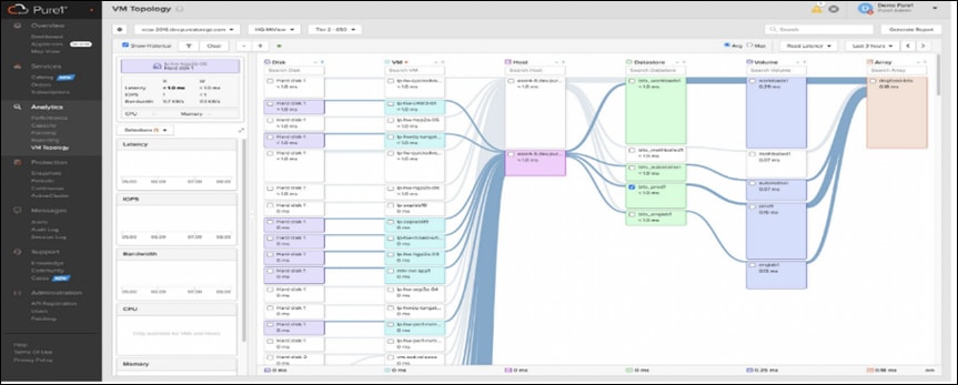
● Intelligent Monitoring and Management
Manage your entire fleet of Pure Storage systems from any device, with just a web browser or the Pure1 mobile application. Pure1 leverages AI to deliver industry-first capabilities that dramatically simplify management and planning. With Pure1, there simply won’t be much for you to do. If something does require attention, the Pure1 mobile app will let you know.
● Analyze
Full-stack analytics (VMA) extends beyond storage, and Pure1 has long featured deep analytics on your storage infrastructure. Pure1 now extends that visibility up the stack to give you deep performance metrics on volumes and VMs in your VMware environments, enabling fast and efficient troubleshooting with visibility throughout the stack. You now have insight into latency, bandwidth, and IOPs of your workflows—and the data point you need to resolve issues quickly and pinpoint latency problems or other bottlenecks.
● Infrastructure Optimization
The Service Assistant regularly checks the Pure1 cloud to determine if the storage infrastructure is running the latest software version. If it is not, it generates alerts to inform the IT team of upgrades to improve operating performance, add new features, and increase reliability. This feature is designed to investigate all Pure portfolio components and is extensible to other alliance offerings. You can expect this feature to expand to support end-to-end infrastructure.
Amazon Web Services (AWS) and Red Hat OpenShift Service on AWS
AWS provides a flexible application computing environment for deploying cloud-native infrastructure and applications. Red Hat OpenShift can accelerate application development and delivery by providing a consistent experience for developers and operators across both on-prem and public cloud. One set of Kubernetes APIs and management tooling, updated on the same schedule, and supported by the same industry-leading vendor, can be deployed across all of enterprise’s cloud and on-premises environments.
AWS is globally available, enabling Enterprises to extend their enterprise deployments to a variety of AWS regions as needed. Red Hat OCP cluster nodes can also be distributed across multiple AWS Availability Zones (AZ) to ensure cluster and application availability.
OCP is available as a managed service on AWS, Red Hat OpenShift Service on AWS (ROSA), and as a self-managed application platform. This solution uses the self-managed service and the openshift-install command line installation method. The automated installation uses several AWS services such as Route 53, DHCP, load balancers, Virtual Private Cloud (VPC) and EC2 instances that are deployed or used as a part of the installation process. Transit Gateways (TGW) attached to the VPC provide connectivity to on-prem resources and services, including K8s clusters and application workloads.
A VPC in AWS provides an isolated virtual networking environment on a shared infrastructure where users can deploy resources to support application workloads. Enterprises can deploy VPCs in AWS cloud and connect them directly to the on-prem datacenter to enable connectivity between applications, services, and resources in each environment. One mechanism for enabling this connectivity is to use a Site-to-Site VPN to establish an IPsec VPN tunnel between the two locations.
Red Hat OpenShift Service on AWS
Red Hat OpenShift Services on AWS (ROSA) is a fully managed application platform that is integrated with AWS and managed by a global team of expert SREs. ROSA enables enterprises to focus on delivering value through their applications and workloads. It’s easy to extend an on-premises OpenShift environment into the public cloud with ROSA’s self-service deployment and robust SLAs.
Infrastructure as Code with Red Hat Ansible
Red Hat Ansible is an open-source tool for Infrastructure as Code (IaC). Ansible is also used for configuration management and application software deployment. Ansible is designed to be agentless, secure, and simple. Ansible available in Red Hat’s Ansible Automation Platform is part of a suite of tools supported by Red Hat. Ansible manages endpoints and infrastructure components in an inventory file, formatted in YAML or INI. The inventory file can be a static file populated by an administrator or dynamically updated. Passwords and other sensitive data can be encrypted using Ansible Vault. Ansible uses playbooks to orchestrate provisioning and configuration management. Playbooks are written in human readable YAML format that is easy to understand. Ansible playbooks are executed against a subset of components in the inventory file. From a control machine, Ansible uses SSH or Windows Remote Management to remotely configure and provision target devices in the inventory based on the playbook tasks.
Ansible is simple and powerful, allowing users to easily manage various physical devices within FlashStack including the configuration of Cisco UCS bare metal servers, Cisco Nexus switches, Pure FlashArray storage and VMware vSphere. Using Ansible’s Playbook-based automation is easy and integrates into your current provisioning infrastructure. This solution offers Ansible Playbooks that are made available from a GitHub repository that customers can access to automate the FlashStack deployment.
VMware vSphere 8.0 has several improvements and simplifications including, but not limited to:
● Limits with vSphere 8 have been increased including number of GPU devices is increased to 8, the number of ESXi hosts that can be managed by Lifecycle Manager is increased from 400 to 1000, the maximum number of VMs per cluster is increased from 8,000 to 10,000, and the number of VM DirectPath I/O devices per host is increased from 8 to 32.
● Security improvements including adding an SSH timeout on ESXi hosts, a TPM Provisioning policy allowing a vTPM to be replaced when cloning VMs, and TLS 1.2 as the minimum supported TLS version.
● Implementation of VMware vMotion Unified Data Transport (UDT) to significantly reduce the time to storage migrate powered off virtual machines.
● Lifecycle Management improvements including VMware vSphere Configuration Profiles as a new alternative to VMware Host Profiles, staging cluster images and remediating up to 10 ESXi hosts in parallel instead of one at a time.
● New Virtual Hardware in VM hardware version 20 supporting the latest guest operating systems, including Windows 11.
● Distributed Resource Scheduler and vMotion improvements.
● Implementation of the VMware Balanced Power Management Policy on each server, which reduces energy consumption with minimal performance compromise.
● Implementation of VMware Distributed Power Management, which along with configuration of the Intelligent Platform Management Interface (IPMI) on each UCS server allows a VMware host cluster to reduce its power consumption by powering hosts on and off based on cluster resource utilization.
For more information about VMware vSphere and its components, go to: https://www.vmware.com/products/vsphere.html
This chapter contains the following:
● Cisco Nexus Ethernet Connectivity
● Cisco MDS SAN Connectivity – Fibre Channel Design
● Cisco UCS X-Series Configuration - Cisco Intersight Managed Mode
● VMware vSphere – ESXi Design
● Pure Storage FlashArray–Storage Design
● Cisco Intersight Integration with FlashStack
● OCP Virtual Networking Design
● Portworx Enterprise Kubernetes Storage Platform Design Considerations
At a high level, the hybrid cloud infrastructure design in this solution consists of an on-prem datacenter, public cloud infrastructure, and a secure network interconnecting the two environments, as shown in Figure 40.
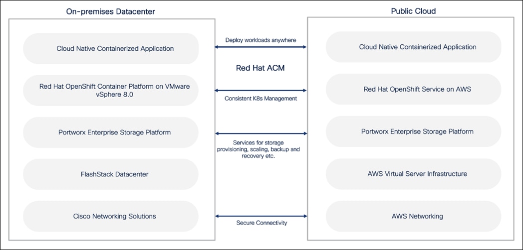
FlashStack Virtual Server Infrastructure (VSI)
The on-premises FlashStack Virtual Server Infrastructure in the solution consists of:
● 6 x Cisco UCS X210c M6 Compute Nodes form VMware vSphere 8.0 cluster. Control plane and worker nodes are running as virtual machines on VMware vSphere 8.0 cluster. There can be more than OCP clusters in a VMware vSphere 8.0 cluster.
● The cluster is deployed and managed from the cloud using Cisco Intersight.
● 2 x Cisco UCS X210c M6 Compute Nodes form a management cluster with VMware vSphere 8.0 cluster hosting services and management components to support the application cluster. The cluster is deployed and managed from the cloud using Cisco Intersight. The services deployed include VMware vCenter managing the application cluster, DNS, DHCP and OCP Installer workstation. The management cluster can also host a management OCP cluster to run services and other components. For example, Red Hat’s Advanced Cluster Manager requires a seed OCP cluster to run on before it can be used for multi-cluster management.
Public Virtual Server Infrastructure
The public Virtual Server Infrastructure in the solution consists of Red Hat OpenShift Service on AWS (ROSA), a fully managed, turnkey application platform.
Network Connectivity
Two redundant IPsec VPN connections provide secure connectivity between the cloud-native environments. The VPN connections are between 2 x CSR1000v routers on-prem and transit gateway routers in the public cloud.
Kubernetes Infrastructure
Red Hat OCP cluster(s) provide a Kubernetes environment for cloud-native applications and use cases. The clusters are deployed on FlashStack Datacenter and on AWS EC2 instances using Red Hat Hybrid Cloud and managed using Red Hat Advanced Cluster Management for Kubernetes.
Portworx Enterprise Kubernetes Storage Platform
Portworx Enterprise provides cloud native storage for applications running in the FlashStack Datacenter and on AWS. Portworx also provides various data services such as:
● PX-DR enables asynchronous disaster recovery for the solution.
● PX-Backup delivers enterprise-grade application and data protection with fast recovery.
● PX Central provides monitoring, metrics, and data management interface for Portworx Enterprise.
Figure 41 illustrates the end-to-end solution that was designed, built, and validated in Cisco internal labs.
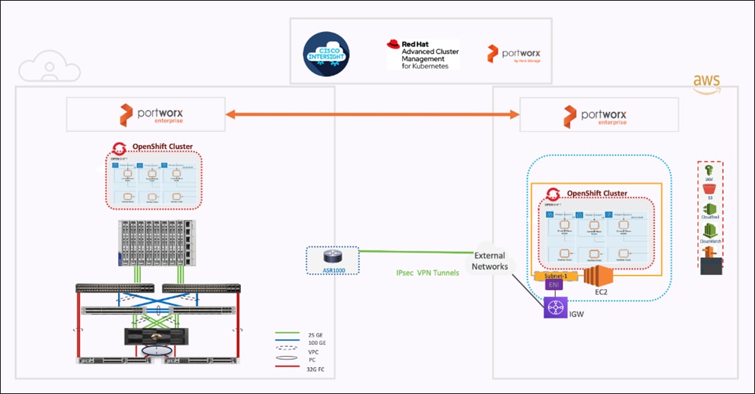
● Cisco UCS X-Series based FlashStack provides customers compute density, expandability, and All flash infrastructure in a single system. Cisco UCS X210c allows customers to utilize the latest hardware innovations for running compute intensive workloads.
● Red Hat Advanced Cluster Management for Kubernetes provides consistent management of OCP clusters with the ability to deploy workloads anywhere, from on-prem to cloud.
● Portworx provides data services across hybrid cloud. Portworx CSI provides dynamic provisioning of persistent storage from FlashStack. Portworx is Red Hat certified and available for deployment on Red Hat’s Operator hub.
● FlashStack and Intersight can quickly deliver a production-ready CI stack for virtualized and containerized workloads.
● Intersight simplifies operations by providing a comprehensive set of day-2 capabilities and tools.
The hybrid cloud infrastructure design in this solution consists of FlashStack Datacenter, AWS public cloud and secure network interconnecting the two environments. Some of the design requirements that this hybrid cloud solution addresses are as follows:
● Central monitoring for clusters, applications, and data.
● Consistent way to access and manage the data, data backup, restore and recovery across hybrid cloud.
● Operational simplicity and agility with the flexibility to deploy and manage workloads anywhere. The on-prem infrastructure that the Enterprise manages, must be easy to deploy and manage without compromising functionality, scale, or performance.
● The infrastructure must also be available as code for integration into existing Enterprise automation or CI/CD pipelines.
Hybrid cloud infrastructure with FlashStack Datacenter aligns with all FlashStack CVDs and meets the following design requirements:
● Resilient design across all layers of the infrastructure with no single point of failure.
● Scalable design with the ability to independently scale compute, storage, and networking as needed.
● Modular design with the ability to upgrade or replace components and sub-systems as needed.
● Flexible design across all layers of the solution that includes sub-system design, individual components used, and storage configuration and connectivity options.
● Operational agility and simplicity through best-of-breed products, SaaS operations, automation, and orchestration tools.
● Incorporates technology and product best practices for the different components in the solution.
For Red Hat OCP 4 integration into a traditional FlashStack solution, the following specific design considerations are also observed:
● Deployment option for one or three control plane nodes, where the option with one control plane node is not recommended for production HA use cases.
● A minimum of 2 worker nodes with ability to increase the nodes as the load requirements increase.
● Automating the FlashStack infrastructure deployment and OCP installation by utilizing Ansible Playbooks to simplify the installation and reduce the deployment time.
● Present persistent storage (volumes) to the containerized applications by utilizing the Portworx CSI.
● Dedicated Cisco UCS vNICs for different traffic needs with UCS Fabric Failover for high availability.
On-premises infrastructure include the FlashStack Datacenter. This FlashStack design utilizes Cisco UCS X-series servers connected to through Cisco UCS Fabric Interconnects and managed with Intersight Infrastructure Manager (IMM).
FlashStack with Cisco UCS X-Series supports both IP-based and Fibre Channel (FC)-based storage access design. For the IP-based solution, iSCSI configuration on Cisco UCS and Pure Storage FlashArray is utilized to set up storage access including boot from SAN configuration for the compute nodes. For the Fibre Channel designs, Pure Storage FlashArray and Cisco UCS X-Series are connected using Cisco MDS 9132T switches and storage access, including boot from SAN, is provided over the Fibre Channel network. The physical connectivity details for both IP and FC designs are explained in the following sections.
IP-based Storage Access: iSCSI
The physical topology for the IP-based FlashStack is shown in Figure 42.
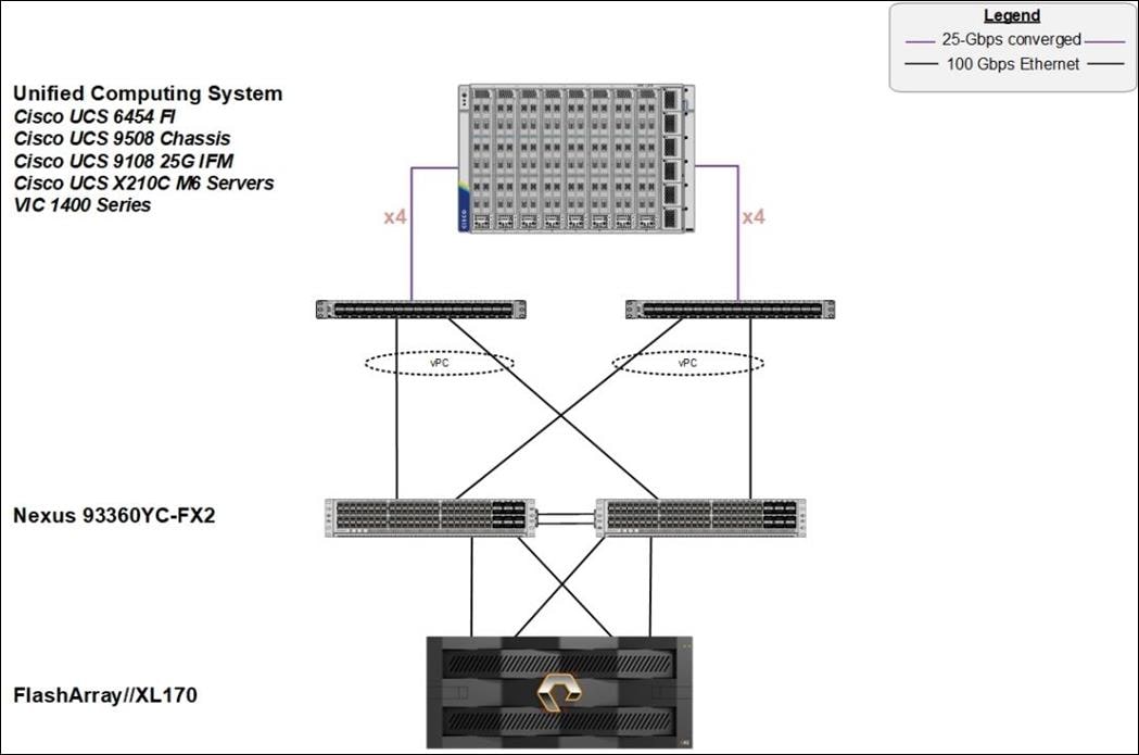
To validate the IP-based storage access in a FlashStack configuration, the components are set up as follows:
● Cisco UCS 6454 Fabric Interconnects provide the chassis and network connectivity.
● The Cisco UCS X9508 Chassis connects to fabric interconnects using Cisco UCSX 9108-25G intelligent fabric modules (IFMs), where four 25 Gigabit Ethernet ports are used on each IFM to connect to the appropriate FI. If additional bandwidth is required, all eight 25G ports can be utilized.
● Cisco UCSX-210c M6 Compute Nodes contain fourth-generation Cisco 14425 virtual interface cards.
● Cisco Nexus 93360YC-FX2 Switches in Cisco NX-OS mode provide the switching fabric.
● Cisco UCS 6454 Fabric Interconnect 100-Gigabit Ethernet uplink ports connect to Cisco Nexus 93360YC-FX2 Switches in a Virtual Port Channel (vPC) configuration.
● The Pure Storage FlashArray//XL170 connects to the Cisco Nexus 93360YC-FX2 switches using four 25-GE ports.
● VMware ESXi 8.0 is installed on Cisco UCSX-210c M6 Compute Nodes to validate the infrastructure.
● Red Hat OpenShift software is installed on VMware vSphere 8.0 cluster.
Fibre Channel-based Storage Access: FC and FC-NVMe
The physical topology of the FlashStack for FC connectivity is shown in Figure 43.
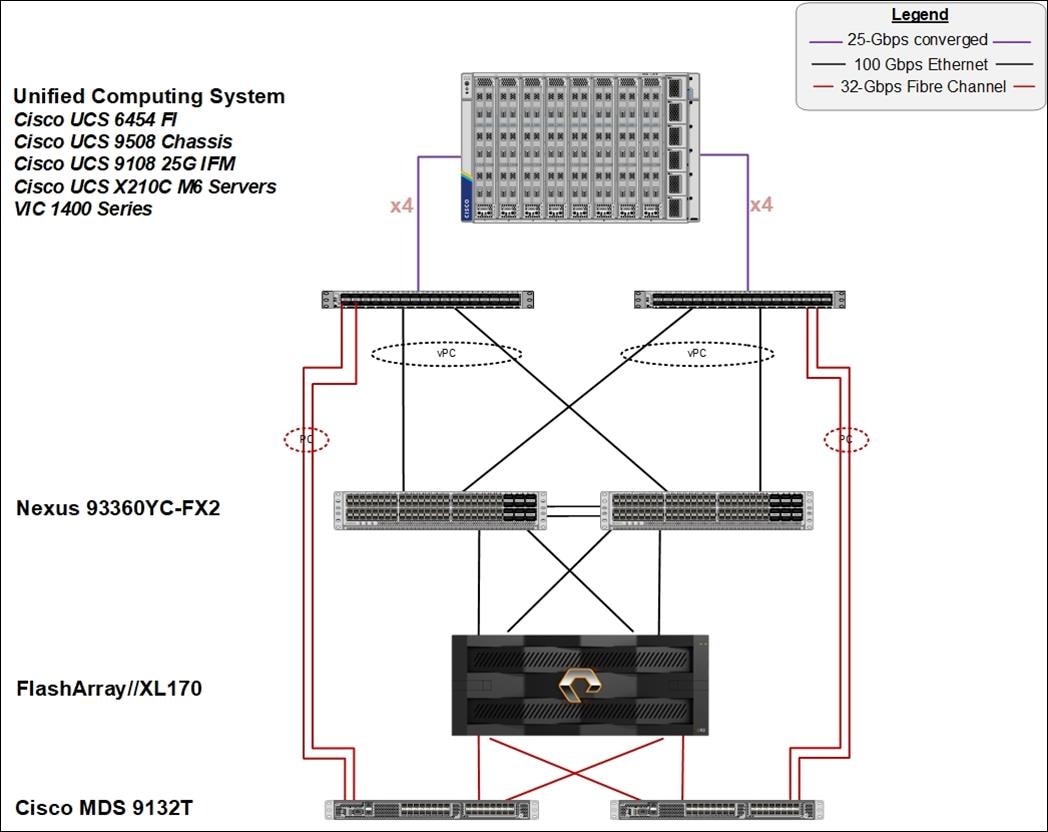
To validate the FC-based storage access in a FlashStack configuration, the components are set up as follows:
● Cisco UCS 6454 Fabric Interconnects provide the chassis and network connectivity.
● The Cisco UCS X9508 Chassis connects to fabric interconnects using Cisco UCSX 9108-25G Intelligent Fabric Modules (IFMs), where four 25 Gigabit Ethernet ports are used on each IFM to connect to the appropriate FI.
● Cisco UCS X210c M6 Compute Nodes contain fourth-generation Cisco 14425 virtual interface cards.
● Cisco Nexus 93360YC-FX2 Switches in Cisco NX-OS mode provide the switching fabric.
● Cisco UCS 6454 Fabric Interconnect 100 Gigabit Ethernet uplink ports connect to Cisco Nexus 93360YC-FX2 Switches in a vPC configuration.
● Cisco UCS 6454 Fabric Interconnects are connected to the Cisco MDS 9132T switches using 32-Gbps Fibre Channel connections configured as a single port channel for SAN connectivity.
● The Pure Storage FlashArray//XL170 connects to the Cisco MDS 9132T switches using 32-Gbps Fibre Channel connections for SAN connectivity.
● VMware ESXi 8.0 is installed on Cisco UCS X210c M6 Compute Nodes to validate the infrastructure.
● Red Hat OpenShift software is installed on VMware vSphere 8.0 cluster.
Table 3 lists the VLANs configured for setting up the FlashStack environment.
| VLAN ID |
Name |
Usage |
| 3 |
Native-VLAN |
Use VLAN 3 as native VLAN instead of default VLAN (1). |
| 1030 |
OOB-MGMT-VLAN |
Out-of-Band Management VLAN to connect the management ports for various devices |
| 1031 |
IB-MGMT-VLAN |
In-Band Management VLAN utilized for all in-band management connectivity for example, ESXi hosts, VM management, and so on. |
| 1032 |
OCP-Data |
Data traffic VLAN from/to RH OCP Virtual Machines |
| 3119 |
iSCSI-A* |
iSCSI-A path for supporting boot-from-san for both Cisco UCS B-Series and Cisco UCS C-Series servers |
| 3219 |
iSCSI-B* |
iSCSI-B path for supporting boot-from-san for both Cisco UCS B-Series and Cisco UCS C-Series servers |
| 3319 |
vMotion |
VMware vMotion traffic. |
| 3419 |
VM-Traffic |
VM data traffic VLAN. |
* iSCSI VLANs are not required if using FC storage connectivity.
Some of the key highlights of VLAN usage are as follows:
● VLAN 1030 allows customers to manage and access out-of-band management interfaces of various devices and is brought into the infrastructure to allow CIMC access to the Cisco UCS servers and is also available to infrastructure virtual machines (VMs). Interfaces in this VLAN are configured with MTU 1500.
● VLAN 1031 is used for in-band management of VMs, hosts, and other infrastructure services. Interfaces in this VLAN are configured with MTU 1500.
● VLAN 1032 is the data traffic network for OCP cluster 1. Interfaces in this VLAN are configured with MTU 9000.
● A pair of iSCSI VLANs (3119 and 3219) is configured to provide access to boot LUNs for ESXi hosts and iSCSI datastores. These VLANs are not needed when configuring Fibre Channel connectivity. Interfaces in these VLANs are configured with MTU 9000.
In FlashStack deployments, each Cisco UCS server equipped with a Cisco Virtual Interface Card (VIC) is configured for multiple virtual Network Interfaces (vNICs), which appear as standards-compliant PCIe endpoints to the OS. The end-to-end logical connectivity including VLAN/VSAN usage between the server profile for an ESXi host and the storage configuration on Pure Storage FlashArray is captured in the following sections.
Logical Topology for IP-based Storage Access
Figure 44 illustrates the end-to-end connectivity design for IP-based storage access.
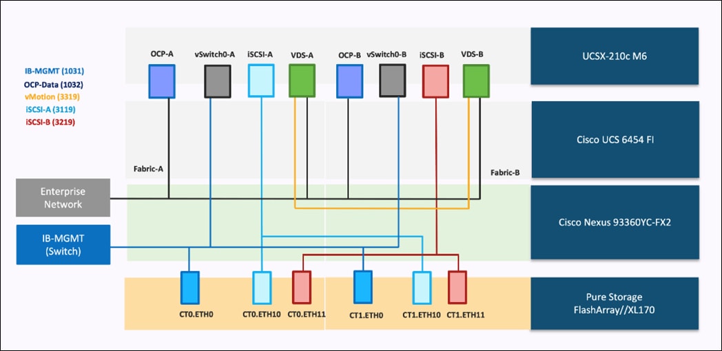
Each ESXi server profile supports:
● Managing the ESXi hosts using a common management segment.
● Diskless SAN boot using iSCSI with persistent operating system installation for true stateless computing.
● Eight vNICs where:
◦ Two redundant vNICs (vSwitch0-A and vSwitch0-B) carry management traffic. The maximum transmission unit (MTU) value for these vNICs is set to 1500.
◦ Two redundant vNICs (OCP-A and OCP-B) carry OCP data traffic. The MTU for the vNICs is set to Jumbo MTU (9000).
◦ The vSphere distributed switch uses two redundant vNICs (VDS-A and VDS-B) to carry VMware vMotion traffic and customer application data traffic. The MTU for the vNICs is set to Jumbo MTU (9000).
◦ The iSCSI-A vSwitch uses one iSCSI-A vNIC to provide access to the iSCSI-A path. The MTU value for the vNIC is set to Jumbo MTU (9000).
◦ The iSCSI-B vSwitch uses one iSCSI-B vNIC to provide access to the iSCSI-B path. The MTU value for this vNIC is set to Jumbo MTU (9000).
● Each ESXi host (compute node) accesses datastores from Pure Storage FlashArray using iSCSI to deploy virtual machines.
Logical Topology for FC-based Storage Access
Figure 45 illustrates the end-to-end connectivity design for FC-based storage access.
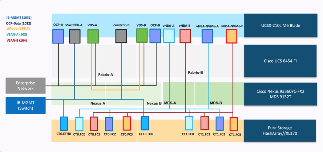
Each ESXi server profile supports:
● Managing the ESXi hosts using a common management segment.
● Diskless SAN boot using Fibre Channel with persistent operating system installation for true stateless computing.
● Six vNICs where:
◦ Two redundant vNICs (vSwitch0-A and vSwitch0-B) carry management traffic. The MTU value for these vNICs is set to 1500.
◦ Two redundant vNICs (OCP-A and OCP-B) carry OCP data traffic. The MTU for the vNICs is set to Jumbo MTU (9000).
◦ The vSphere Distributed switch uses two redundant vNICs (VDS-A and VDS-B) to carry VMware vMotion traffic and customer application data traffic. The MTU for the vNICs is set to Jumbo MTU (9000).
● Four vHBAs where:
◦ One vHBA (vHBA-A) defined on Fabric A provides access to the SAN-A path (FC Initiator).
◦ One vHBA (vHBA-B) defined on Fabric B provides access to the SAN-B path (FC Initiator).
◦ One vHBA (vHBA-NVMe-A) defined on Fabric A provides access to the SAN-A path for NVMe over Fabric traffic (FC-NVMe Initiator).
◦ One vHBA (vHBA-NVMe-B) defined on Fabric B provides access to the SAN-B path for NVMe over Fabric traffic (FC-NVMe Initiator).
● Each ESXi host (compute node) accesses datastores from Pure Storage FlashArray using Fibre Channel to deploy virtual machines.
The Cisco UCS X9508 Chassis is equipped with the Cisco UCSX 9108-25G intelligent fabric modules (IFMs). The Cisco UCS X9508 Chassis connects to each Cisco UCS 6454 FI using four 25GE ports, as shown in Figure 46. If you require more bandwidth, all eight ports on the IFMs can be connected to each FI.
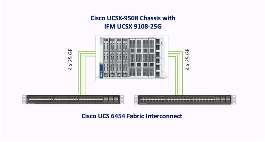
Cisco Nexus Ethernet Connectivity
The Cisco Nexus 93360YC-FX2 device configuration covers the core networking requirements for Layer 2 and Layer 3 communication. Some of the key NX-OS features implemented within the design are:
● Feature interface-vlan – Allows for VLAN IP interfaces to be configured within the switch as gateways.
● Feature HSRP – Allows for Hot Standby Routing Protocol configuration for high availability.
● Feature LACP – Allows for the utilization of Link Aggregation Control Protocol (802.3ad) by the port channels configured on the switch.
● Feature vPC – Virtual Port-Channel (vPC) presents the two Nexus switches as a single “logical” port channel to the connecting upstream or downstream device.
● Feature LLDP - Link Layer Discovery Protocol (LLDP), a vendor-neutral device discovery protocol, allows the discovery of both Cisco devices and devices from other sources.
● Feature NX-API – NX-API improves the accessibility of CLI by making it available outside of the switch by using HTTP/HTTPS. This feature helps with configuring the Cisco Nexus switch remotely using the automation framework.
● Feature UDLD – Enables unidirectional link detection for various interfaces.
Cisco UCS Fabric Interconnect 6454 Ethernet Connectivity
Cisco UCS 6454 FIs are connected to Cisco Nexus 93360YC-FX2 switches using 100GE connections configured as virtual port channels. Each FI is connected to both Cisco Nexus switches using a 100G connection; additional links can easily be added to the port channel to increase the bandwidth as needed. Figure 47 illustrates the physical connectivity details.
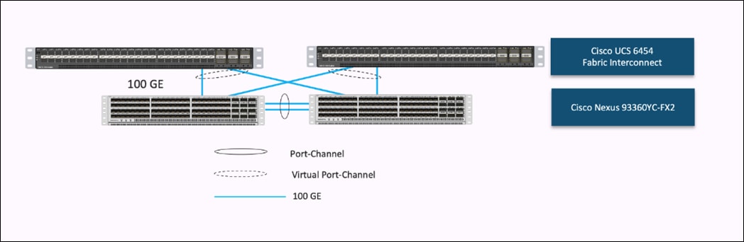
Pure Storage FlashArray//XL170 Ethernet Connectivity
Pure Storage FlashArray controllers are connected to Cisco Nexus 93360YC-FX2 switches using redundant 100-GE. Figure 48 illustrates the physical connectivity details.
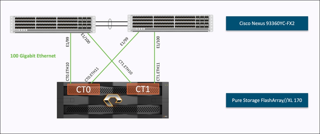
Cisco MDS SAN Connectivity – Fibre Channel Design
The Cisco MDS 9132T is the key design component bringing together the 32Gbps Fibre Channel (FC) capabilities to the FlashStack design. A redundant 32 Gbps Fibre Channel SAN configuration is deployed utilizing two MDS 9132Ts switches. Some of the key MDS features implemented within the design are:
● Feature NPIV – N port identifier virtualization (NPIV) provides a means to assign multiple FC IDs to a single N port.
● Feature fport-channel-trunk – F-port-channel-trunks allow for the fabric logins from the NPV switch to be virtualized over the port channel. This provides nondisruptive redundancy should individual member links fail.
● Smart-Zoning – a feature that reduces the number of TCAM entries by identifying the initiators and targets in the environment.
Cisco UCS Fabric Interconnect 6454 SAN Connectivity
For SAN connectivity, each Cisco UCS 6454 Fabric Interconnect is connected to a Cisco MDS 9132T SAN switch using 2 x 32G Fibre Channel port-channel connection, as shown in Figure 49.
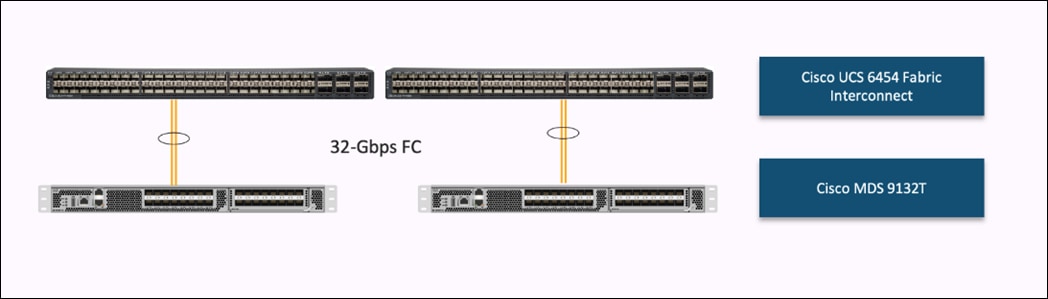
Pure Storage FlashArray//XL170 SAN Connectivity
For SAN connectivity, each FlashArray controller is connected to both of Cisco MDS 9132T SAN switches using 32G Fibre Channel connections, as shown in Figure 50.
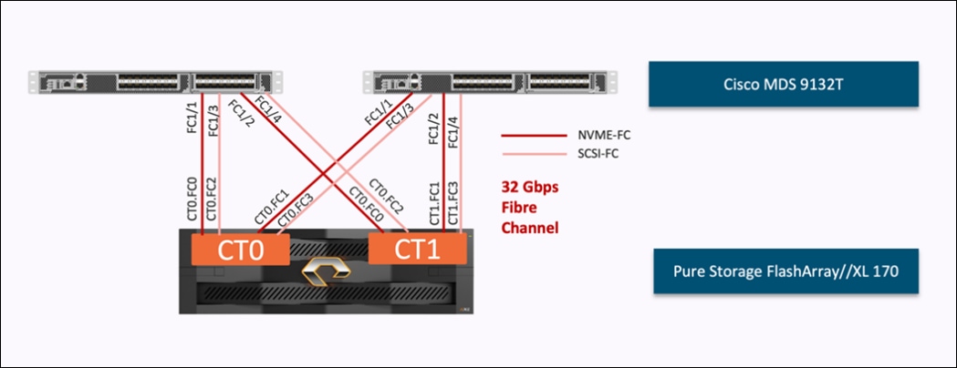
Cisco UCS X-Series Configuration - Cisco Intersight Managed Mode
Cisco Intersight Managed Mode standardizes policy and operation management for Cisco UCS X-Series. The compute nodes in Cisco UCS X-Series are configured using server profiles defined in Cisco Intersight. These server profiles derive all the server characteristics from various policies and templates. At a high level, configuring Cisco UCS using Intersight Managed Mode consists of the steps shown in Figure 51.
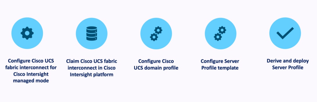
Set Up Cisco UCS Fabric Interconnect for Cisco Intersight Managed Mode
During the initial configuration, for the management mode the configuration wizard enables customers to choose whether to manage the fabric interconnect through Cisco UCS Manager or the Cisco Intersight platform. Customers can switch the management mode for the fabric interconnects between Cisco Intersight and Cisco UCS Manager at any time; however, Cisco UCS FIs must be set up in Intersight Managed Mode (IMM) for configuring the Cisco UCS X-Series system. Figure 52 shows the dialog during initial configuration of Cisco UCS FIs for setting up IMM.
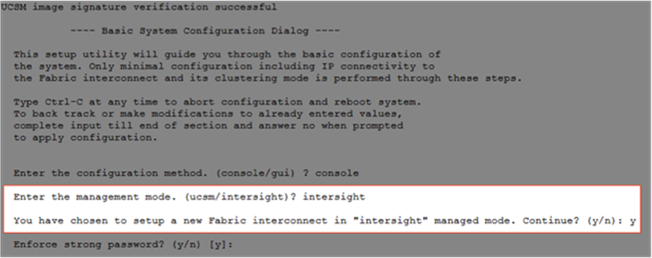
Claim a Cisco UCS Fabric Interconnect in the Cisco Intersight Platform
After setting up the Cisco UCS 6454 Fabric Interconnect for Cisco Intersight Managed Mode, FIs can be claimed to a new or an existing Cisco Intersight account. When a Cisco UCS Fabric Interconnect is successfully added to Cisco Intersight, all future configuration steps are completed in the Cisco Intersight portal.
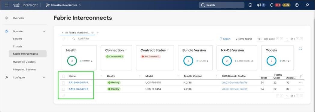
You can verify whether a Cisco UCS Fabric Interconnect is in Cisco UCS Manager managed mode or Cisco Intersight Managed Mode by clicking on the fabric interconnect name and looking at the detailed information screen for the FI, as shown in Figure 54.
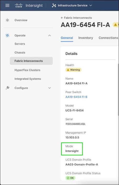
Cisco UCS Chassis Profile
A Cisco UCS Chassis profile configures and associates the chassis policy to a Cisco UCS chassis. The chassis profile feature is available in Intersight only if customers have installed the Intersight Essentials License. The chassis-related policies can be attached to the profile either at the time of creation or later.
The chassis profile in a FlashStack is used to set the power policy for the chassis. By default, Cisco UCS X-Series power supplies are configured in GRID mode, but power policy can be utilized to set the power supplies in non-redundant or N+1/N+2 redundant modes.
Cisco UCS Domain Profile
A Cisco UCS domain profile configures a fabric interconnect pair through reusable policies, allows configuration of the ports and port channels, and configures the VLANs and VSANs to be used in the network. It defines the characteristics of and configures the ports on the fabric interconnects. One Cisco UCS domain profile can be assigned to one fabric interconnect domain.
Some of the characteristics of the Cisco UCS domain profile in the FlashStack environment are:
● A single domain profile is created for the pair of Cisco UCS fabric interconnects.
● Unique port policies are defined for the two fabric interconnects.
● The VLAN configuration policy is common to the fabric interconnect pair because both fabric interconnects are configured for the same set of VLANs.
● The VSAN configuration policies (FC connectivity option) are unique for the two fabric interconnects because the VSANs are unique.
● The Network Time Protocol (NTP), network connectivity, and system Quality-of-Service (QoS) policies are common to the fabric interconnect pair.
After the Cisco UCS domain profile has been successfully created and deployed, the policies including the port policies are pushed to Cisco UCS Fabric Interconnects. Cisco UCS domain profile can easily be cloned to install additional Cisco UCS systems. When cloning the UCS domain profile, the new UCS domains utilize the existing policies for consistent deployment of additional Cisco UCS systems at scale.
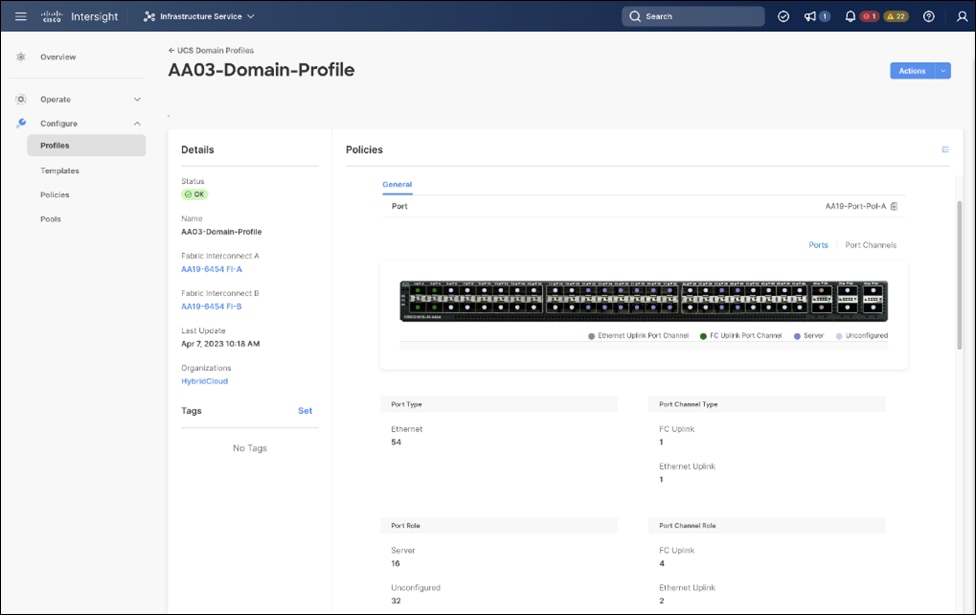
The Cisco UCS X9508 Chassis and Cisco UCS X210c M6 Compute Nodes are automatically discovered when the ports are successfully configured using the domain profile as shown in the following figures:
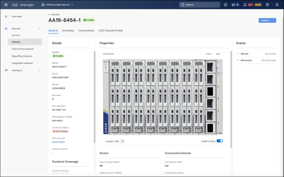
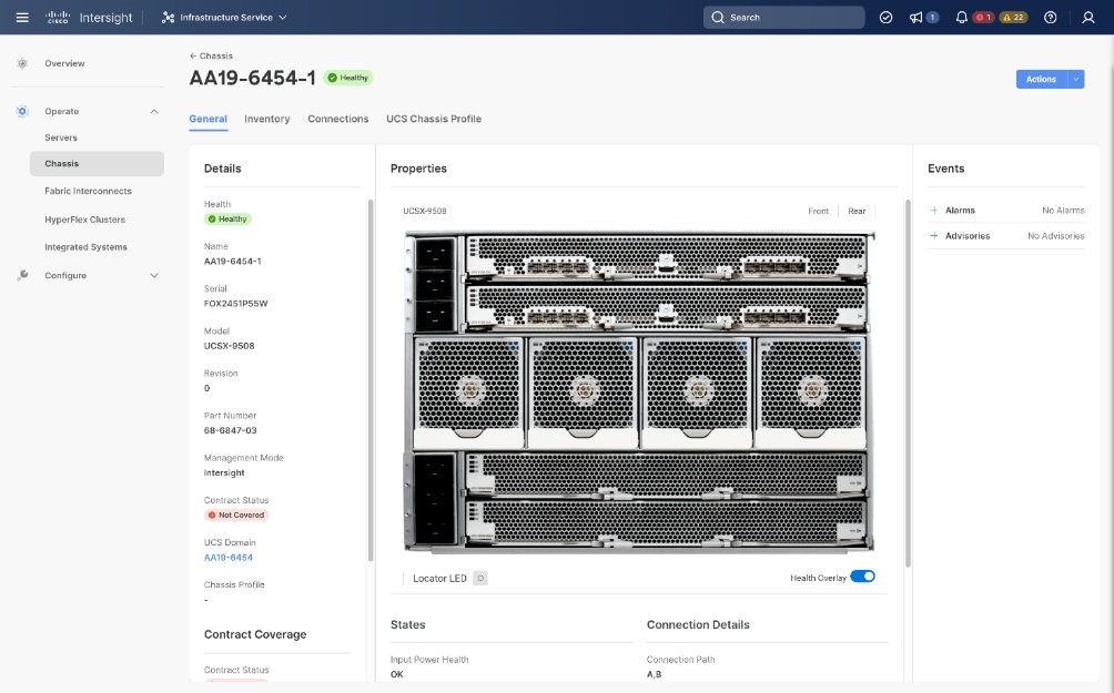
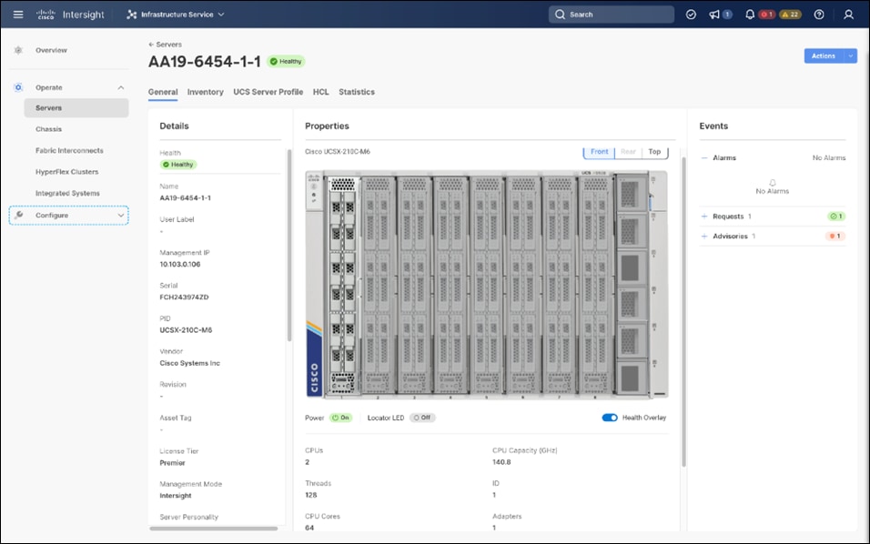
Server Profile Template
A server profile template enables resource management by simplifying policy alignment and server configuration. A server profile template is created using the server profile template wizard. The server profile template wizard groups the server policies into the following four categories to provide a quick summary view of the policies that are attached to a profile:
● Compute policies: BIOS, boot order, and virtual media policies.
● Network policies: adapter configuration, LAN connectivity, and SAN connectivity policies.
◦ The LAN connectivity policy requires you to create Ethernet network policy, Ethernet adapter policy, and Ethernet QoS policy.
◦ The SAN connectivity policy requires you to create Fibre Channel (FC) network policy, Fibre Channel adapter policy, and Fibre Channel QoS policy. SAN connectivity policy is only required for the FC connectivity option.
● Storage policies configure local storage and are not used in FlashStack.
● Management policies: device connector, Intelligent Platform Management Interface (IPMI) over LAN, Lightweight Directory Access Protocol (LDAP), local user, network connectivity, Simple Mail Transfer Protocol (SMTP), Simple Network Management Protocol (SNMP), Secure Shell (SSH), Serial over LAN (SOL), syslog, and virtual Keyboard, Video, and Mouse (KVM) policies
Some of the characteristics of the server profile template for FlashStack are:
● BIOS policy is created to specify various server parameters in accordance with FlashStack best practices.
● Boot order policy defines virtual media (KVM mapper DVD), all SAN paths for Pure Storage FlashArray (iSCSI or Fibre Channel interfaces), and UEFI Shell.
● IMC access policy defines the management IP address pool for KVM access.
● Local user policy is used to enable KVM-based user access.
● For the iSCSI boot from SAN configuration, LAN connectivity policy is used to create eight virtual network interface cards (vNICs) — two for management virtual switch (vSwitch0), two for OpenShift Container Platform data, two for application Virtual Distributed Switch (VDS), and one each for iSCSI A/B vSwitches. Various policies and pools are also created for the vNIC configuration.
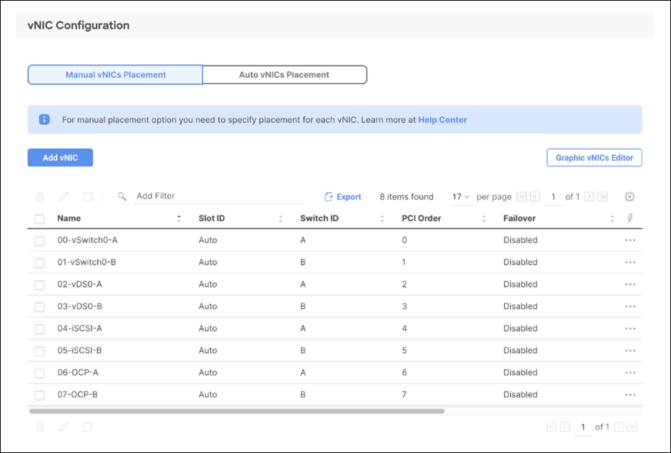
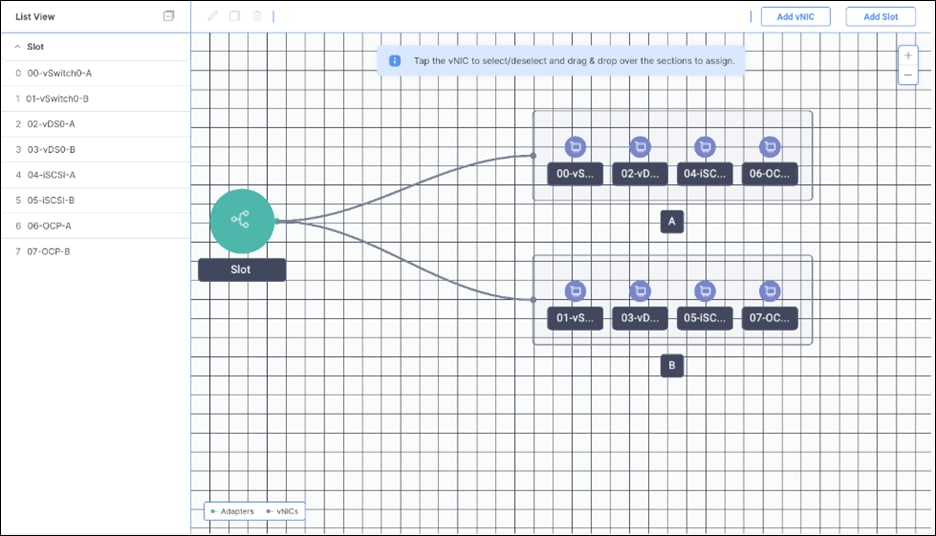
● 4th Generation Cisco UCS VICs supports up to 4096 Receive and Transmit ring sizes. Therefore, the Ethernet Adapter policy can be configured accordingly while creating iSCSI vNICS for optimized performance.
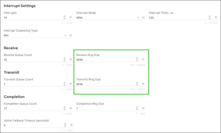
● For the FC boot from SAN configuration, LAN connectivity policy is used to create six vNICs — two for management virtual switches (vSwitch0), two for OpenShift Container Platform data and two for application VDS — along with various policies and pools.
● For the FC connectivity option, SAN connectivity policy is used to create four virtual host bus adapters (vHBAs) — along with various policies and pools. 2 vHBAs (vHBA-A and vHBA-B) are of vHBA type “fc-inititator” and 2 vHBAs (vHBA-NVMe-A and vHBA-NVMe-B) are of vHBA type “fc-nvme-initiator”. The SAN connectivity policy is not required for iSCSI setup.
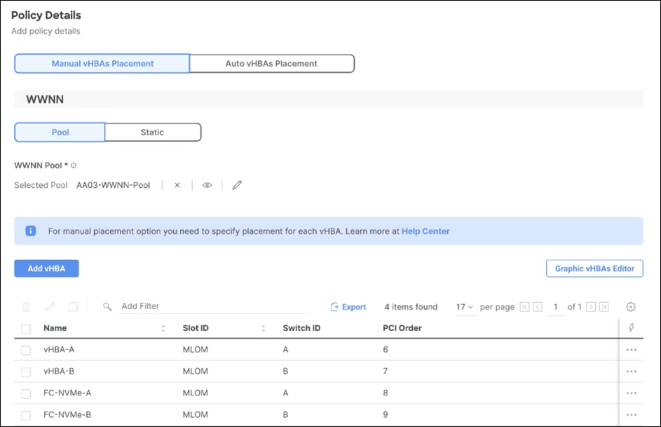
Figure 63 shows various policies associated with the server profile template.
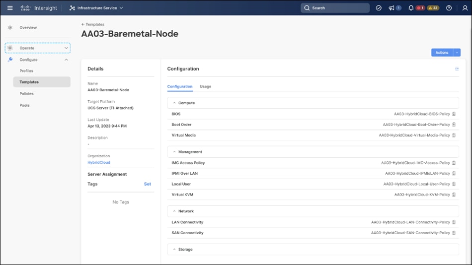
Multiple vNICs (and vHBAs) are created for the ESXi hosts using the Cisco Intersight server profile and are then assigned to specific virtual and distributed switches. The vNIC and (optional) vHBA distribution for the ESXi hosts is as follows:
● Two vNICs (one on each fabric) for vSwitch0 to support core services such as management traffic.
● Two vNICs (one on each fabric) for OCP-Data vSwitch for OpenShift Container Platform data traffic.
● Two vNICs (one on each fabric) for vSphere Virtual Distributed Switch (VDS) to support customer data traffic and vMotion traffic.
● One vNIC each for Fabric-A and Fabric-B for iSCSI stateless boot. These vNICs are only required when iSCSI boot from SAN configuration is desired.
● One vHBA each for Fabric-A and Fabric-B for FC stateless boot. These vHBAs are only required when FC connectivity is desired.
The following figures illustrate how the ESXi vNIC configurations in detail:
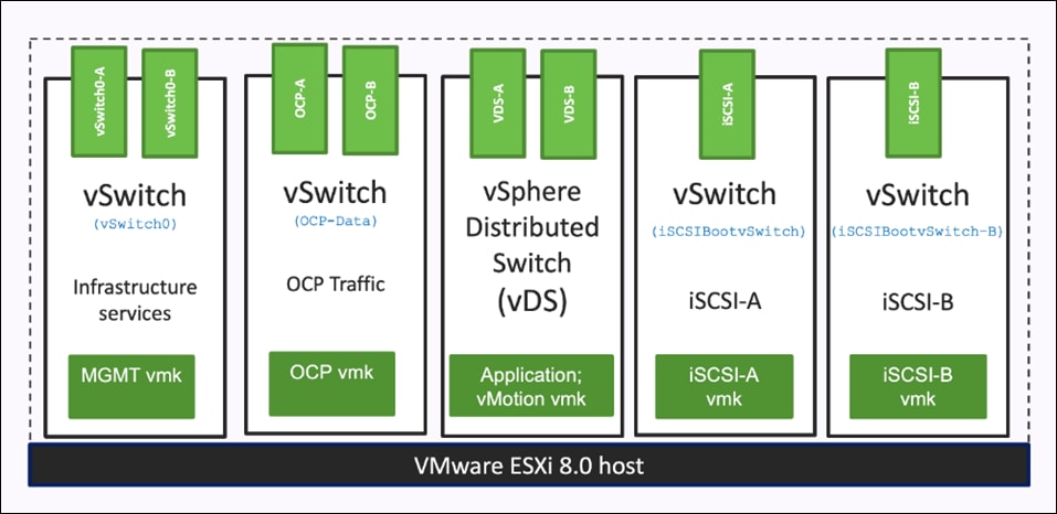
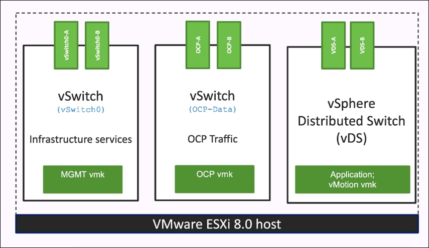
Pure Storage FlashArray – Storage Design
To set up Pure Storage FlashArray you must configure the following items:
● Volumes
◦ ESXi boot LUNs: These LUNs enable ESXi host boot from SAN functionality using iSCSI or Fibre Channel.
◦ The vSphere environment: vSphere uses the infrastructure datastore(s) to store the virtual machines.
● Hosts
◦ All FlashArray ESXi hosts are defined.
◦ Add every active initiator for a given ESXi host.
● Host groups
◦ All ESXi hosts in a VMware cluster are part of the host group.
◦ Host groups are used to mount VM infrastructure datastores in the VMware environment.
The volumes, interfaces, and VLAN/VSAN details are shown in the following figures for iSCSI and Fibre Channel connectivity, respectively.
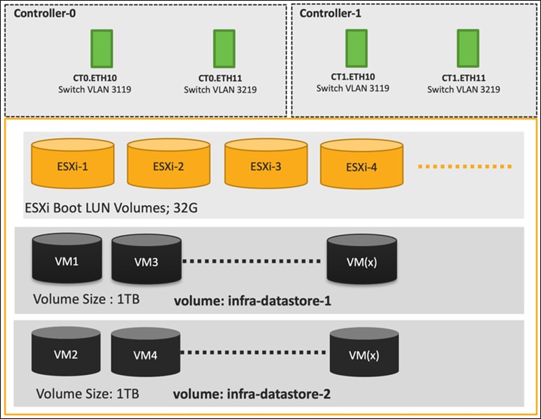
Along with SCSI-FC, solution also implements NVMe using the FC-NVMe protocol over a SAN built using Cisco MDS switches. NVMe initiators consisting of Cisco UCS X210C servers installed with Cisco VIC adapters can access Pure FlashArray NVMe targets over Fibre Channel.
Each port on the Pure FlashArray can be configured as traditional scsi-fc port or as a nvme-fc port to support NVMe end-to-end via fibre channel from the host to storage array. Note that a given FC port is either going to be SCSI or NVMe, not on the FlashArray.
Two ports on each Pure FlashArray controllers are configured as SCSI ports and the other two are configured as NVMe ports in this design validation as shown in Figure 67.
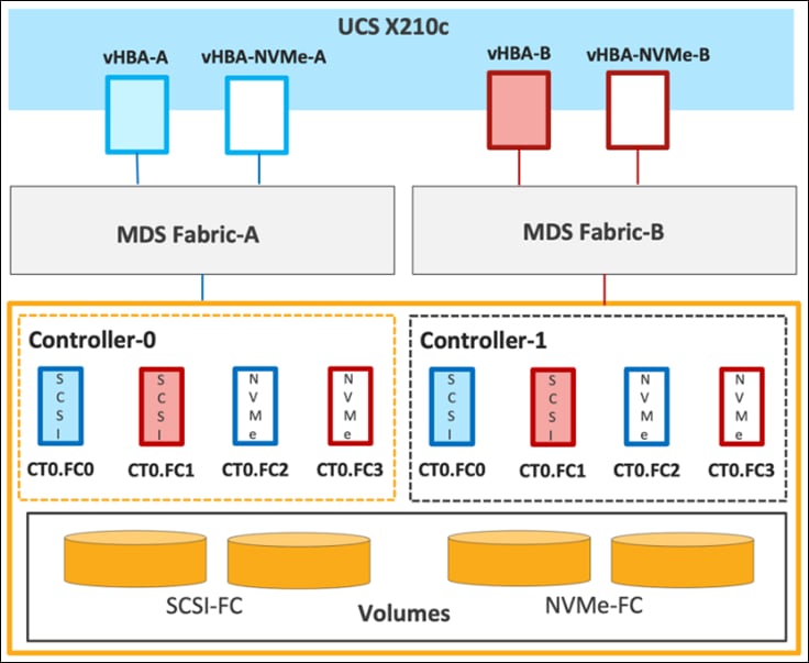
Cisco UCS provides a unified fabric that is an architectural approach delivering flexibility, scalability, intelligence, and simplicity. This flexibility allows Cisco UCS to readily support new technologies such as FC-NVMe seamlessly. In a Cisco UCS service profile, both standard Fibre Channel and FC-NVMe vHBAs can be created.
Both Fibre Channel and FC-NVMe vHBAs can exist in a Cisco UCS service profile on a single server. In the lab validation for this document, four vHBAs (one FC-NVME initiator on each Fibre Channel fabric and one Fibre Channel initiator on each Fibre Channel fabric) were created in each service profile. Each vHBA, regardless of type, was automatically assigned a worldwide node name (WWNN) and a worldwide port name (WWPN). The Cisco UCS fabric interconnects were in Fibre Channel end-host mode (NPV mode) and uplinked through a SAN port channel to the Cisco MDS 9132T switches in NPV mode. Zoning in the Cisco MDS 9132T switches connected the vHBAs to storage targets for both FC-NVMe and Fibre Channel. Single-initiator, multiple-target zones were used for both FCP and FC-NVMe.
The ESXi automatically connects to Pure FlashArray NVMe subsystem and discovers all shared NVMe storage devices that it can reach once the SAN zoning on MDS switches, and the configuration of host/host groups and volumes is completed on the Pure FlashArray.
Pure Storage FlashArray Considerations
Connectivity
● Each FlashArray Controller should be connected to BOTH storage fabrics (A/B).
● Make sure to include I/O Cards which supports 25 GE are installed in original FlashArray BOM
● Pure Storage offers up to 32Gb FC support on the FlashArray//X and 64Gb FC on the latest FlashArray//XL series arrays. Always make sure the correct number of HBAs and SFPs (with appropriate speed) are included in the original FlashArray BOM.
● For NVME-FC, make sure to include the I/O controller interfaces with service “Nvme-fc”.
Host Groups and Volumes
It is a best practice to map Hosts to Host Groups and the Host Groups to Volumes in Purity. This ensures the Volume is presented on the same LUN ID to all hosts and allows for simplified management of ESXi Clusters across multiple nodes.
Size of the Volume
Purity removes the complexities of aggregates and RAID groups. When managing storage, a volume should be created based on the size required and purity takes care of availability and performance via RAID-HD and DirectFlash software. Customers can create 1 10-TB volume or 10 1-TB volumes and the performance and availability for these volumes will always be consistent. This feature allows customers to focus on recoverability, manageability, and administrative considerations of volumes instead of dwelling on availability or performance.
vCenter Deployment Consideration
While hosting the vCenter on the same ESXi hosts that the vCenter will manage is supported, it is a best practice to deploy the vCenter on a separate management infrastructure. The ESXi hosts in this new FlashStack with Cisco UCS X-Series environment can also be added to an existing customer vCenter. The in-band management VLAN will provide connectivity between the vCenter and the ESXi hosts deployed in the new FlashStack environment.
An MTU of 9216 is configured at all network levels to allow jumbo frames as needed by the guest OS and application layer. The MTU value of 9000 is used on all the vSwitches and vSphere Distributed Switches (VDS) in the VMware environment.
Boot From SAN
When utilizing Cisco UCS Server technology with shared storage, it is recommended to configure boot from SAN and store the boot LUNs on remote storage. This enables architects and administrators to take full advantage of the stateless nature of Cisco UCS X-Series Server Profiles for hardware flexibility across the server hardware and overall portability of server identity. Boot from SAN also removes the need to populate local server storage thereby reducing cost and administrative overhead.
UEFI Boot
This validation of FlashStack uses Unified Extensible Firmware Interface (UEFI). UEFI is a specification that defines a software interface between an operating system and platform firmware.
NVMe over Fabrics
NVMe over Fabrics (NVMe-oF) is an extension of the NVMe network protocol to Ethernet and Fibre Channel delivering faster and more efficient connectivity between storage and servers as well as a reduction in CPU utilization of application host servers. This validation of FlashStack supports NVMe over Fibre Channel (NVMe/FC) to provide the high-performance and low-latency benefits of NVMe across fabrics. In this solution, NVMe initiators consisting of Cisco UCS X210c compute nodes access Pure FlashArray NVMe targets over Fibre Channel.
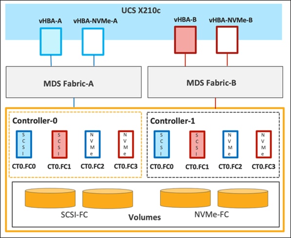
Each port on the Pure FlashArray can be configured as traditional scsi-fc port or as a nvme-fc port to support NVMe end-to-end via fibre channel from the host to storage array. Two ports on each Pure Storage FlashArray controller are configured as SCSI ports and two ports are configured as NVMe ports as shown in Figure 68.
Note: A given FC port on Pure Storage FlashArray can either be configured as FC-SCSI or FC-NVMe port.
In a Cisco UCS server profile, both standard Fibre Channel and FC-NVMe vHBAs can be created. A default Fibre Channel adapter policy named fc-nvme-initiator is preconfigured in Cisco Intersight. This policy contains recommended adapter settings for FC-NVMe. Both Fibre Channel and FC-NVMe vHBAs can exist in a Cisco UCS server profile on a single server.
To support NVMe over Fabric, four vHBAs, two FC-NVME initiators and two Fibre Channel initiators (one on each Fibre Channel fabric), are created for each server profile. Cisco MDS 9132T switches are configured with appropriate zoning to connect the FC-NVMe and Fibre Channel vHBAs to appropriate storage targets. Single-initiator, multiple-target zones are used for both FCP and FC-NVMe. VMware ESXi automatically connects to Pure FlashArray NVMe subsystem and discovers all shared NVMe storage devices that it can reach once the SAN zoning on MDS switches, and the configuration of host/host groups and volumes is completed on the Pure FlashArray.
Cisco Intersight Integration with FlashStack
Cisco Intersight enhances the ability to provide complete visibility, orchestration, and optimization across all elements of FlashStack datacenter. This empowers customers to make intelligent deployment decisions, easy management, optimize cost and performance and maintain supported configurations for their infrastructure.
Cisco Intersight works with Pure Storage FlashArray, VMware vCenter using third-party device connectors. Since third-party infrastructure does not contain any built-in Intersight device connector, Cisco Intersight Assist virtual appliance enables Cisco Intersight to communicate with these non-Cisco devices. Also, Physical, and logical inventories of Ethernet and Storage area networks are available within Intersight.
Note: A single Cisco Intersight Assist virtual appliance can support both Pure Storage FlashArray and VMware vCenter.
Cisco Intersight integration with VMware vCenter, Pure Storage FlashArrays, Nexus and MDS switches enables customers to perform following tasks right from the Intersight dashboard:
● Monitor the virtualization of storage and network environment.
● Add various dashboard widgets to obtain useful at-a-glance information.
● Perform common Virtual Machine tasks such as power on/off, remote console and so on.
● Orchestration of Virtual, Storage and network environment to perform common configuration tasks.
● Extend optimization capability for entire FlashStack datacenter.
The following sections explain the details of these operations. Since Cisco Intersight is a SaaS platform, the monitoring and orchestration capabilities are constantly being added and delivered seamlessly from the cloud.
Note: The monitoring capabilities and orchestration tasks and workflows listed below provide an in-time snapshot for your reference. For the most up to date list of capabilities and features, you should use the help and search capabilities in Cisco Intersight.
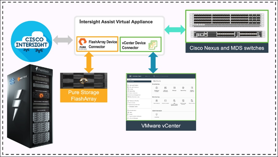
Integrate Cisco Intersight with Pure Storage FlashArray
To integrate Pure Storage FlashArray with the Cisco Intersight platform, you must deploy a Cisco Intersight Assist virtual appliance and claim Pure Storage FlashArray as a target in the Cisco Intersight application, as shown in Figure 70.
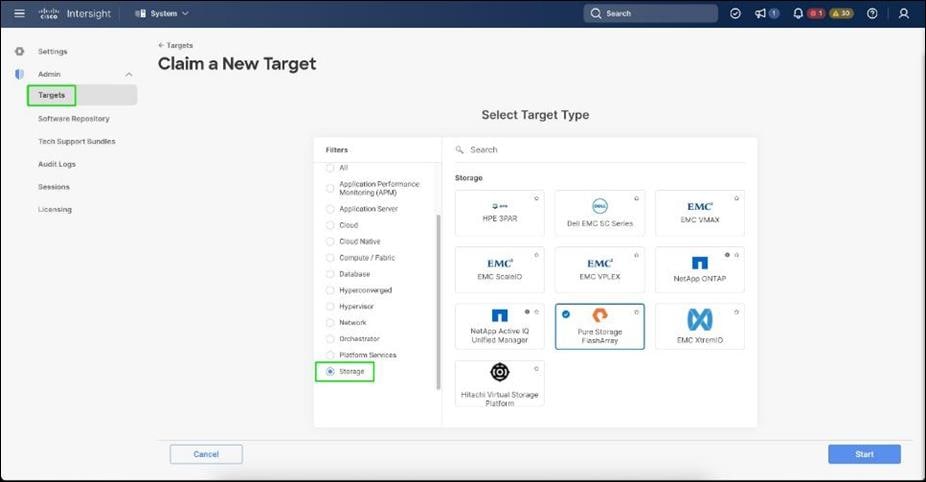
After successfully claiming Pure Storage FlashArray as a target, you can view storage-level information in Cisco Intersight.
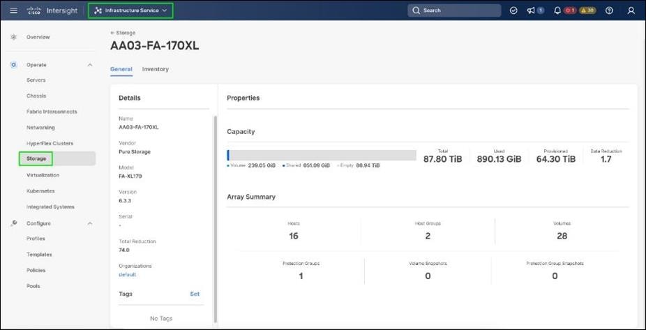
Cisco Intersight Cloud Orchestrator provides various workflows that can be used to automate storage provisioning. Some of the storage workflows available for Pure Storage FlashArray are listed in Figure 72.
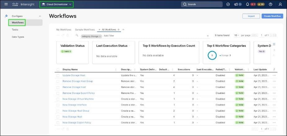
Integrate Cisco Intersight with VMware vCenter
To integrate VMware vCenter with Cisco Intersight, VMware vCenter can be claimed as a target using Cisco Intersight Assist Virtual Appliance, as shown in Figure 73.
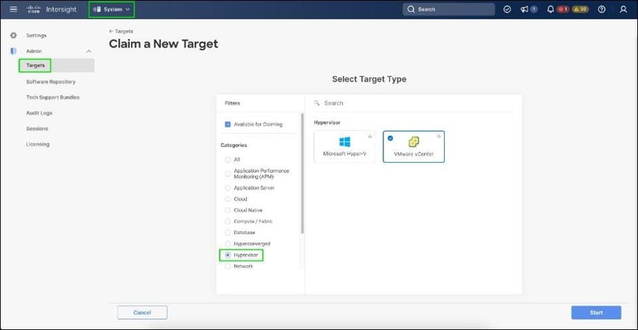
After successfully claiming the VMware vCenter as a target, you can view hypervisor-level information in Cisco Intersight including hosts, VMs, clusters, datastores, and so on.
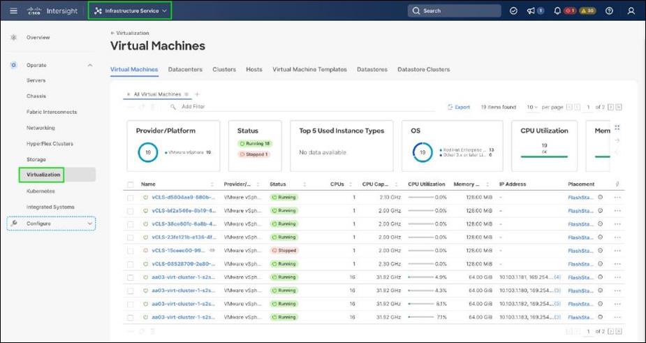
VMware vCenter integration with Cisco Intersight allows you to directly interact with the virtual machines (VMs) from the Cisco Intersight dashboard. In addition to obtaining in-depth information about a VM, including the operating system, CPU, memory, host name, and IP addresses assigned to the virtual machines, you can use Intersight to perform various actions.
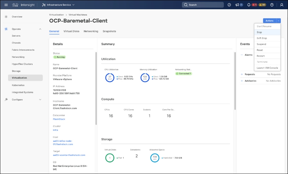
Cisco Intersight Cloud Orchestrator provides various workflows that can be used for the VM and hypervisor provisioning.
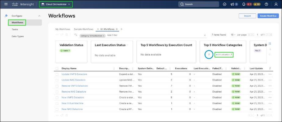
Integrate Cisco Intersight with Nexus and MDS Switches
To integrate Cisco Nexus and MDS switches with Cisco Intersight, Cisco Nexus and MDS switches can be claimed as a target using Cisco Intersight Assist Virtual Appliance deployed earlier.
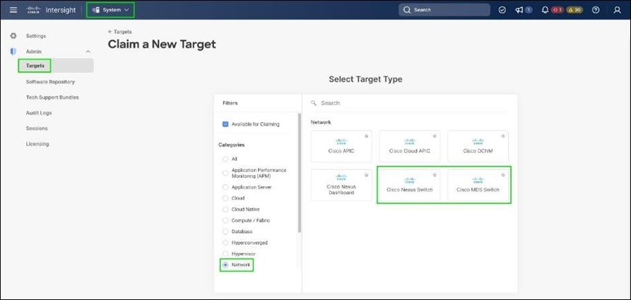
After successfully claiming the Cisco Nexus and MDS switches as targets, you can view their Ethernet and SAN details in Cisco Intersight including Physical and logical inventory.
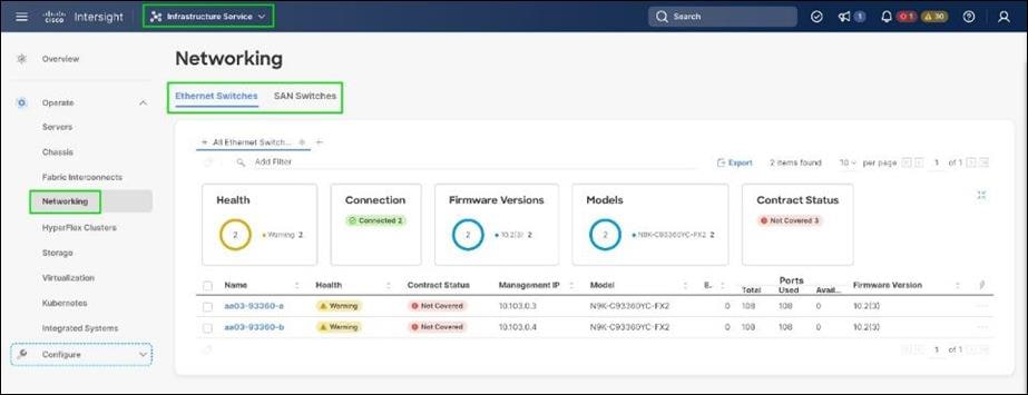
Red Hat OpenShift Container Platform On-Premises
● OpenShift can run on-premises either on a virtualization layer or directly on bare metal. Integration with bare metal includes use of Redfish Virtual Media and/or IPMI to directly control local servers through their baseboard management controllers. OpenShift uses the Metal3 project for Kubernetes-native bare metal management.
● A typical highly-available OpenShift cluster will have three control plane nodes and two or more worker nodes. For a smaller HA footprint, three nodes can each act as part of the control plane and also accept workloads.
● OpenShift includes a rich set of observability features. Metrics, logs, and alerts can be viewed and consumed with built-in features and tools, and they can also be published to a variety of third-party systems.
● On-premises infrastructure is sometimes disconnected or air-gapped for security purposes. OpenShift offers a complete first-class experience for securely deploying clusters and delivering updates to all layers of the cluster infrastructure, including the operating system, core Kubernetes, additional Kubernetes-related components (observability, storage, network management, developer workflows, and so on), management tooling, and optional Kubernetes Operators.
● The systems underlying each node can be optimized using the Node Tuning Operator. The TuneD daemon is used in a similar manner as with Red Hat Enterprise Linux; a performance profile is either created or selected from the list of built-in profiles, and then the TuneD daemon uses that profile on each system to configure kernel features such as CPU assignments and the low-latency and determinism of the realtime kernel.
● Each OpenShift release includes a specific version of RHEL CoreOS and all of the OpenShift components. There is no need to provision and maintain a base operating system, because OpenShift includes the OS in its installation and ongoing management.
● OpenShift Virtualization is an add-on to OpenShift Container Platform that enables virtual machines to be run and managed in Pods alongside containerized workloads. Kubernetes-native APIs enable virtual machines to be created, managed, imported, cloned, and live-migrated to other nodes.
Red Hat OpenShift Service on AWS
● ROSA provides a fully-managed application platform that is seamlessly integrated with AWS services and backed by a global team of SREs.
● ROSA is deployed and billed directly through an AWS account.
● A ROSA cluster can optionally be deployed across multiple availability zones, which enhances the opportunity for the cluster and its workloads to remain highly available through an infrastructure disruption. Best practices should still be followed for application high availability, such as the use of Pod Disruption Budgets, which help keep a service running through voluntary / expected disruption (such as nodes upgrading in-place during a cluster upgrade).
● ROSA has a variety of industry standard security and control certifications, including HIPAA and PCI DSS. A complete list is available in the documentation.
● Auto-scaling can be configured to add and remove compute nodes in a ROSA cluster based on pod scheduling pressure. A minimum and maximum number of compute nodes can be configured to ensure that a predictable footprint remains available.
● The ROSA-CLI is used to deploy Red Hat OpenShift on AWS to the AWS environment.
The OpenShift Container Platform cluster uses a virtualized network for pod and service networks. The OVN-Kubernetes Container Network Interface (CNI) plug-in is a network provider for the default cluster network. A cluster that uses the OVN-Kubernetes network provider also runs Open vSwitch (OVS) on each node. OVN configures OVS on each node to implement the declared network configuration.
The OVN-Kubernetes default Container Network Interface (CNI) network provider implements the following features:
● Uses OVN (Open Virtual Network) to manage network traffic flows. OVN is a community developed, vendor agnostic network virtualization solution.
● Implements Kubernetes network policy support, including ingress and egress rules.
● Uses the Geneve (Generic Network Virtualization Encapsulation) protocol rather than VXLAN to create an overlay network between nodes.
Internal and external OCP Virtual Networking Design is shown in Figure 79.
Control Plane nodes and worker nodes, connect to two networks; OVN-Kubernetes that OpenShift manages and then the physical datacenter network.
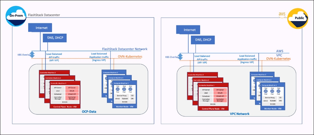
By default, Kubernetes (and OCP) allocates each pod an internal cluster-wide IP address that it can use for Pod-to-Pod communication. Within a Pod, all containers behave as if they’re on the same logical host and communicate with each other using localhost, using the ports assigned to the containers. All containers within a Pod can communicate with each other using the Pod network.
For communication outside the cluster, OCP provides services (node ports, load balancers) and API resources (Ingress, Route) to expose an application or a service outside cluster so that users can securely access the application or service running on the OCP cluster. API resources, Ingress and Routes are used in this solution to expose the application deployed in the OCP cluster.
Portworx Enterprise Kubernetes Storage Platform Design Considerations
Sizing of Disks
When sizing the disks, it is recommended to configure volumes with adequate capacity for any given workload to be deployed in the cluster. If an application requires 500GB of capacity, then configure more than 500GB per node using the configuration wizard. This could be a quantity of four 150GB EBS volumes, or one large 600GB volume.
Additionally, it is recommended to configure PX- Autopilot to protect applications from downtime related to filling the PVCs in use and the Portworx cluster.
Prerequisites for Portworx on VMware vSphere:
● VMware vSphere version 7.0 or newer.
● kubectl configured on the machine having access to the cluster.
● Portworx does not support the movement of VMDK files from the datastores on which they were created.
● Cluster must be running OpenShift 4 or higher and the infrastructure that meets the minimum requirements for Portworx.
● Virtual Machines used for OpenShift nodes for Portworx have Secure Boot disabled.
For more information, see: https://docs.portworx.com/install-portworx/prerequisites/
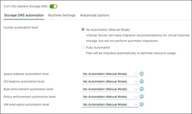
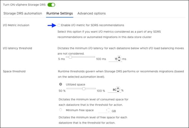
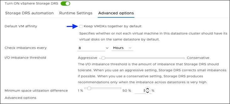
vCenter environment variables and User privileges for Portworx:
● A Kubernetes secret with vCenter User and password.
● Generate a spec of vSphere environment variables like hostname of vCenter, port number, datastore prefix and other variables.
● Generate and apply a spec file.
● Administrator has to create a disk template which Portworx will use the disk template as a reference for creating disks, virtual volumes for PVCs.
Table 4. vCenter User privileges
|
|
|
|
| Allocate space |
Local operations |
Change Configuration |
| Browse datastore |
Reconfigure virtual machine |
Add existing disk |
| Low level file operations |
|
Add new disk |
| Remove file |
Add or remove device |
|
|
|
Advanced configuration |
|
| Change Settings |
||
| Extend virtual disk |
||
| Modify device settings |
||
| Remove disk |
Note: If you create a custom role as shown above, make sure to select “Propagate to children” when assigning the user to the role.
Disk Provisioning of Portworx on Vmware vSphere
● Pure Storage FlashArray XL provides block storage (vVOLs, FC and iSCSI) to ESXi hypervisors.
● VMware vSphere datastores are created on the vCenter and Users can create a vSphere datastore cluster.
● vSphere datastore clusters are accessed by Portworx storage.
● Portworx runs on each Kubernetes worker Node and on each node will create its disk on the configured shared datastores or datastore clusters.
● Portworx will aggregate all of the disks and form a single storage cluster. Administrators can carve PVCs (Persistent Volume Claims), PVs (Persistent Volumes) and Snapshots from this storage cluster.
● Portworx tracks and manages the disks that it creates. In a failure event, if a new VM spins up, then the new VM will be able to attach to the same disk that was previously created by the node on the failed VM.
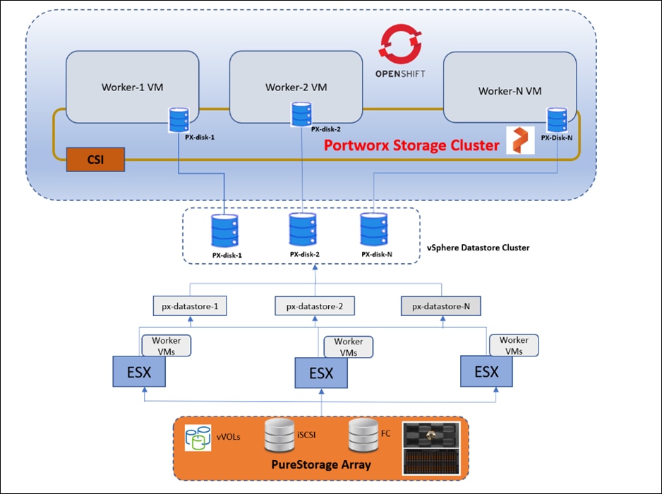
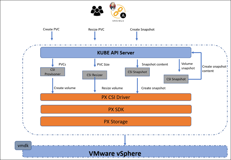
● Portworx provides dynamic disk provisioning on the OpenShift Container Platform running on VMware vSphere.
● Portworx includes a number of default StorageClasses, which can reference with PersistentVolumeClaims (PVCs).
● Portworx CSI driver is API layer in-between the Kubernetes and Portworx SDK.
● Portworx SDK uses either the default gRPC port 9020 or the default REST Gateway port 9021.
● OpenStorage SDK can be plugged into CSI Kubernetes and Docker volumes.
● PX-Storage provides cloud native storage for application running in the cloud, on-prem or hybrid platforms.
● Here PX-Storage communicates with the VMware vSphere vmdk to process the requests.
● Portworx supports:
◦ Provision, attach and mount volumes
◦ CSI snapshots
◦ Stork
◦ Volume expansion or resizing
Deployment Hardware and Software
This chapter contains the following:
It is important to note that the validated FlashStack solution explained in this document adheres to Cisco, Pure Storage, and VMware interoperability matrix to determine support for various software and driver versions. You should use the same interoperability matrix to determine support for components that are different from the current validated design.
Click the following links for more information:
● Pure Storage Interoperability Matrix. Note, this interoperability list will require a support login form Pure:
https://support.purestorage.com/FlashArray/Getting_Started/Compatibility_Matrix
● Pure Storage FlashStack Compatibility Matrix. Note, this interoperability list will require a support login from Pure:
https://support.purestorage.com/FlashStack/Product_Information/FlashStack_Compatibility_Matrix
● Cisco UCS Hardware and Software Interoperability Tool:
http://www.cisco.com/web/techdoc/ucs/interoperability/matrix/matrix.html
● VMware Compatibility Guide:
http://www.vmware.com/resources/compatibility/search.php
Table 5 lists the required hardware components used to build the validated solution. You are encouraged to review your requirements and adjust the size or quantity of various components as needed.
Table 5. FlashStack Datacenter with Red Hat OCP Hardware Components
| Component |
Hardware |
Comments |
|
| Fabric Interconnects |
Two Cisco UCS Fabric Interconnects such as Cisco UCS 6454 FI |
FI generation dependent on the speed requirement. 4th Generation supports 25Gbps and 5th Generation supports 100Gbps end-to-end. |
|
| Pure Storage FlashArray |
Pure Storage FlashArray storage with appropriate capacity and network connectivity such as FlashArray //X50 R3, FlashArray//XL170 |
Customer requirements will determine the amount of storage. The FlashArray should support both 25Gbps or 100 Gbps ethernet and 32Gbps or 6416 Gbps FC connectivity |
|
| Cisco Nexus Switches |
Two Cisco Nexus 93000 series switches such as Cisco Nexus 93360YC-FX2 |
The switch model is dependent on the number of ports and the port speed required for the planned installation. |
|
| Cisco MDS Switches |
Two Cisco MDS 9100 series switches, i.e. MDS 9132T |
The supported port speed of the selected MDS switch must match the port speed of the Fabric Interconnect and the FlashArray. |
|
| Management Cluster Compute |
|||
| Cisco UCS Servers
|
A minimum of two Cisco UCS servers to host management components like Intersight Assist, DHCP, DNS, Active Directory etc
|
To reduce the number of physical servers the use of a supported virtualization software like VMware ESXi is recommended.
|
|
| Red Hat OCP Compute |
|||
| Cisco UCS Chassis |
A minimum of one UCS X9508 chassis |
Single chassis can host up to 8 Cisco UCS X210c compute nodes |
|
| Cisco UCS Compute Nodes |
Cisco UCS X210c compute nodes dependent on the workload planned on the cluster. |
|
|
Table 6 lists the software releases used in the solution. Device drivers, software tools and Cisco Intersight Assist versions will be explained in the deployment guide.
Table 6. Software Components and Hardware
| Component |
Software Version |
|
| Network |
Cisco Nexus9000 C93360YC-FX2 |
10.2(3) |
| Cisco MDS 9132T |
8.4(2c) |
|
| Compute |
Cisco UCS Fabric Interconnect 6454 |
4.2(3b) |
| Cisco UCS UCSX 9108-25G IFM |
4.2(3b) |
|
| Cisco UCS X210C Compute Nodes |
5.0(4a) |
|
| Cisco UCS VIC 14425 installed on X210c |
5.2(3c) |
|
| VMware ESXi |
8.0 |
|
| Storage |
Pure Storage FlashArray//XL170 |
6.3.3 |
| Pure Storage VASA Provider |
3.5 |
|
| Pure Storage Plugin |
5.0.0 |
|
| Kubernetes |
Red Hat OpenShift Container Platform |
4.12 |
| Portworx Enterprise Kubernetes Storage Platform |
2.13 |
|
A repository is created in GitHub which Ansible playbooks to configure all the components of FlashStack including:
● Cisco UCS in Intersight Managed Mode
● Cisco Nexus Switches
● Cisco MDS Switches
● Pure FlashArray
● VMware ESXi
● VMware vCenter
Figure 85 illustrates the FlashStack with X-Series modular platform solution implementation workflow with Ansible.
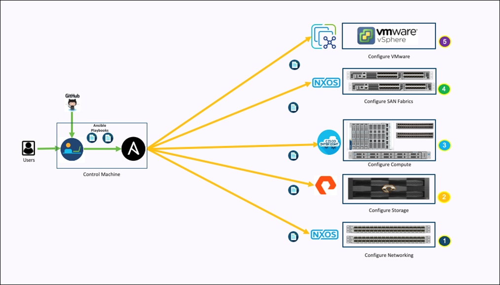
Ansible playbooks to configure the different sections of the solution invoke a set of Roles and consume the associated variables that are required to setup the solution. The variables needed for this solution can be split into two categories – user input and defaults/ best practices. Based on the installation environment customers can choose to modify the variables to suit their requirements and proceed with the automated installation.
Setting up the solution begins with a management workstation that has access to the internet and has a working installation of Ansible. The management workstation runs a variant of Linux or MacOS for ease of use with these command-line-based tools. Instructions for installing the workstation are not included in this document, but the basic installation and configuration of Ansible is explained. The following is a list of prerequisites:
● To use the Ansible playbooks demonstrated in this document, the management workstation must also have a working installation of Git and access to the GitHub repository. The Ansible playbooks used in this document are cloned from the public repositories, located here: https://github.com/ucs-compute-solutions/FlashStack_OCP_vSphere_Ansible
● The Cisco Nexus Switches, Pure Storage and Cisco UCS must be physically racked, cabled, powered, and configured with the management IP addresses before the Ansible-based installation procedure can begin.
● Before running each Ansible Playbook to setup the Network, Storage and Cisco Intersight, various variables must be updated based on the customers environment and specific implementation with values such as the VLANs, pools and ports on Cisco UCS, IP addresses for iSCSI interfaces and values needed for the OCP installation.
For more information, see: Getting Started with Red Hat Ansible
Note: Installing Red Hat OCP and ROSA are performed using automated installers and therefore it will not have the Ansible playbook.
This chapter contains the following:
● Red Hat Open Shift and Red Hat ACM
A high-level overview of the validation for Hybrid Cloud infrastructure solution is provided in this section. Solution validation covers various aspects of the FlashStack Datacenter (Including compute, virtualization, network, and storage), Red Hat OpenShift Container Platform (OCP) and Portworx Enterprise Storage.
The goal of solution validation is to test functional aspects of the design and unless explicitly called out, the performance and scalability is not covered during solution validation. As part of the validation effort, solution validation team identifies the problems, works with the appropriate development teams to fix the problem, and provides work arounds as necessary.
The test scenarios of FlashStack infrastructure are divided into the following broad categories:
● Data path Validation - Ethernet and Fibre Channel data path
● Functional validation – physical and logical setup validation
● Feature verification – feature verification for FlashStack design
● Availability testing – link and device redundancy and high availability testing
Red Hat Open Shift and Red Hat ACM
Test scenarios for Red Hat OpenShift container platform and Red Hat ACM include:
● Application deployment to different clusters across hybrid cloud
● Management of cluster and cluster lifecycle
● Day two operations
● Cloud native storage for applications running in the cloud, on-prem and in hybrid multi-cloud environments
● Kubernetes backup and restore
● Asynchronous disaster recovery
● Centralized monitoring, metrics, and data management
Automation
Infrastructure as a code validation; verify automation and orchestration of solution components.
The Hybrid Cloud infrastructure solution using FlashStack Datacenter, Red Hat OpenShift Container Platform (OCP) and Portworx Enterprise Kubernetes Storage Platform provides a flexible foundational hybrid cloud architecture that enterprises can adopt and standardize on from enterprise edge to core datacenters for containerized workloads.
The solution enables an enterprise-grade Kubernetes environment for an Enterprise’s cloud native efforts across hybrid cloud environment. Solution entitles enterprise level support from Cisco, Pure Storage and Red Hat. Cisco FlashStack is an essential building block that provides the fastest path to hybrid cloud with enterprise-grade, software-defined compute, and storage infrastructure. Coupled with Cisco Intersight, FlashStack can be deployed and managed with simplicity and ease across all Enterprise locations, around the globe. Cisco Intersight can deliver a production-ready Virtual Server Infrastructure (VSI) in less than an hour using a fully automated deployment process. The SaaS model enables install, deploy, monitor, and maintain clusters wherever they reside from a central portal. Intersight offers a comprehensive set of day-2 management capabilities that greatly simplifies and accelerates operations. It includes features such as cluster expansion, full-stack upgrades, day-2 storage management with performance monitoring, connected TAC support, hardware compatibility checks and tools for capacity planning and cluster health checks. Red Hat OpenShift Container Platform provides an enterprise-grade Kubernetes platform with consistent management and development experience across a hybrid environment for both operations and development teams. Portworx offers enterprises with persistent storage, backup and disaster recovery and automated capacity management for Kubernetes apps.
Some of the key advantages of integrating Cisco UCS X-Series and Cisco Intersight into the FlashStack infrastructure are:
● Enables End-to-end 25/40/100G Ethernet and 32/64G Fibre Channel
● Simpler and programmable infrastructure
● Power and cooling innovations and better airflow
● Fabric innovations for heterogeneous compute and memory composability
● Innovative cloud operations providing continuous feature delivery
● Future-ready design built for investment protection
This appendix contains the following:
● Compute
● Portworx
● Network
● Storage
GitHub repository for solution deployment: https://github.com/ucs-compute-solutions/FlashStack_OCP_vSphere_Ansible
Cisco Intersight: https://www.intersight.com
Cisco Intersight Managed Mode: https://www.cisco.com/c/en/us/td/docs/unified_computing/Intersight/b_Intersight_Managed_Mode_Configuration_Guide.html
Cisco Unified Computing System: http://www.cisco.com/en/US/products/ps10265/index.html
Cisco UCS 6500 Series Fabric Interconnects: https://www.cisco.com/c/en/us/products/collateral/servers-unified-computing/ucs6536-fabric-interconnect-ds.html
Documentation: https://docs.openshift.com/
Red Hat OpenShift Container Platform: https://www.redhat.com/en/technologies/cloud-computing/openshift/container-platform
Red Hat Hybrid Cloud Console: https://cloud.redhat.com/
Red Hat Advanced Cluster Management for Kubernetes: https://www.redhat.com/en/technologies/management/advanced-cluster-management
Red Hat OpenShift Service on AWS: https://aws.amazon.com/rosa/
Documentation: https://docs.portworx.com/
Portworx release notes: https://docs.portworx.com/release-notes/portworx/#2-13-2
Cisco Nexus 9000 Series Switches: http://www.cisco.com/c/en/us/products/switches/nexus-9000-series-switches/index.html
Cisco MDS 9132T Switches: https://www.cisco.com/c/en/us/products/collateral/storage-networking/mds-9100-series-multilayer-fabric-switches/datasheet-c78-739613.html
Pure Storage FlashArray//X: https://www.purestorage.com/products/nvme/flasharray-x.html
Pure Storage FlashArray//XL: https://www.purestorage.com/products/nvme/flasharray-xl.html
VMware vCenter Server: http://www.vmware.com/products/vcenter-server/overview.html
VMware vSphere: https://www.vmware.com/products/vsphere
Cisco UCS Hardware Compatibility Matrix: https://ucshcltool.cloudapps.cisco.com/public/
VMware and Cisco Unified Computing System: http://www.vmware.com/resources/compatibility
Pure Storage Interoperability Matrix. Note, this interoperability list will require a support login form Pure: https://support.purestorage.com/FlashArray/Getting_Started/Compatibility_Matrix
Pure Storage FlashStack Compatibility Matrix. Note, this interoperability list will require a support login from Pure: https://support.purestorage.com/FlashStack/Product_Information/FlashStack_Compatibility_Matrix
Paniraja Koppa, Technical Marketing Engineer, Cisco Systems, Inc.
Paniraja Koppa is a member of Cisco’s Cloud and Compute group with a primary focus on data center and cloud technologies. In his current role, he works on design and development, best practices, optimization, automation and technical content creation of compute and hybrid cloud solutions. Prior to this, he has led QA efforts for four new virtual adapter cards for Cisco UCS. He also worked as technical consulting engineer in the data center virtualization space. Paniraja holds a master’s degree in computer science. He has presented several papers at international conferences and speaker at events like Cisco Live US and Europe, Open Infrastructure Summit, and other partner events.
Michael Hrivnak, Senior Principal Software Engineer, Red Hat
Michael Hrivnak is a Senior Principal Software Engineer and Software Architect at Red Hat, where he’s been focused on container technology since 2014. He’s been a leader in developing early registry and distribution technology, the Operator SDK, and Kubernetes-native infrastructure management, especially on bare metal. Michael has presented training and seminars around the world, and today he enjoys solving industry-specific problems with partners as a member of Red Hat’s Ecosystem Engineering group.
Vijay Kulari, Senior Solutions Architect, Pure Storage, Inc.
Vijay Kulari works at Pure Storage and is part of the Solutions team with a primary focus on data center, container and VMware, cloud, and storage technologies.
Acknowledgements
For their support and contribution to the design, validation, and creation of this Cisco Validated Design, the author would like to thank:
● Chris O'Brien, Director, UCS Solutions, Cisco Systems, Inc.
● Rohit Mittal, Product Manager, Cisco Systems, Inc.
● Ulrich Kleidon, Principal Engineer, Cisco Systems, Inc.
● Archana Sharma, Technical Leader, Cisco Systems, Inc.
● Lester Claudio, Senior Principal Software Engineer, Red Hat
● Yevgeny Shnaidman, Principal Software Engineer, Red Hat
● Geet Jain, QA Engineer, Portworx, PureStorage
● Sanjay Naikwadi, Solution Architect, Portworx, PureStorage
● Joe Houghes, Senior Systems Engineer, Pure Storage Inc.
● Craig Waters, Technical Director, Cisco Solutions, Pure Storage Inc.
For comments and suggestions about this guide and related guides, join the discussion on Cisco Community at https://cs.co/en-cvds.
CVD Program
ALL DESIGNS, SPECIFICATIONS, STATEMENTS, INFORMATION, AND RECOMMENDATIONS (COLLECTIVELY, "DE-SIGNS") IN THIS MANUAL ARE PRESENTED "AS IS," WITH ALL FAULTS. CISCO AND ITS SUPPLIERS DISCLAIM ALL WAR-RANTIES, INCLUDING, WITHOUT LIMITATION, THE WARRANTY OF MERCHANTABILITY, FITNESS FOR A PARTICULAR PURPOSE AND NONINFRINGEMENT OR ARISING FROM A COURSE OF DEALING, USAGE, OR TRADE PRACTICE. IN NO EVENT SHALL CISCO OR ITS SUPPLIERS BE LIABLE FOR ANY INDIRECT, SPECIAL, CONSEQUENTIAL, OR INCIDENTAL DAMAGES, INCLUDING, WITHOUT LIMITATION, LOST PROFITS OR LOSS OR DAMAGE TO DATA ARISING OUT OF THE USE OR INABILITY TO USE THE DESIGNS, EVEN IF CISCO OR ITS SUPPLIERS HAVE BEEN ADVISED OF THE POSSIBILITY OF SUCH DAMAGES.
THE DESIGNS ARE SUBJECT TO CHANGE WITHOUT NOTICE. USERS ARE SOLELY RESPONSIBLE FOR THEIR APPLICA-TION OF THE DESIGNS. THE DESIGNS DO NOT CONSTITUTE THE TECHNICAL OR OTHER PROFESSIONAL ADVICE OF CISCO, ITS SUPPLIERS OR PARTNERS. USERS SHOULD CONSULT THEIR OWN TECHNICAL ADVISORS BEFORE IMPLE-MENTING THE DESIGNS. RESULTS MAY VARY DEPENDING ON FACTORS NOT TESTED BY CISCO.
CCDE, CCENT, Cisco Eos, Cisco Lumin, Cisco Nexus, Cisco StadiumVision, Cisco TelePresence, Cisco WebEx, the Cisco logo, DCE, and Welcome to the Human Network are trademarks; Changing the Way We Work, Live, Play, and Learn and Cisco Store are service marks; and Access Registrar, Aironet, AsyncOS, Bringing the Meeting To You, Catalyst, CCDA, CCDP, CCIE, CCIP, CCNA, CCNP, CCSP, CCVP, Cisco, the Cisco Certified Internetwork Expert logo, Cisco IOS, Cisco Press, Cisco Systems, Cisco Systems Capital, the Cisco Systems logo, Cisco Unified Computing System (Cisco UCS), Cisco UCS B-Series Blade Servers, Cisco UCS C-Series Rack Servers, Cisco UCS S-Series Storage Servers, Cisco UCS Manager, Cisco UCS Management Software, Cisco Unified Fabric, Cisco Application Centric Infrastructure, Cisco Nexus 9000 Series, Cisco Nexus 7000 Series. Cisco Prime Data Center Network Manager, Cisco NX-OS Software, Cis-co MDS Series, Cisco Unity, Collaboration Without Limitation, EtherFast, EtherSwitch, Event Center, Fast Step, Follow Me Browsing, FormShare, GigaDrive, HomeLink, Internet Quotient, IOS, iPhone, iQuick Study, LightStream, Linksys, MediaTone, MeetingPlace, MeetingPlace Chime Sound, MGX, Networkers, Networking Academy, Network Registrar, PCNow, PIX, PowerPanels, ProConnect, ScriptShare, SenderBase, SMARTnet, Spectrum Expert, StackWise, The Fastest Way to Increase Your Internet Quotient, TransPath, WebEx, and the WebEx logo are registered trade-marks of Cisco Systems, Inc. and/or its affiliates in the United States and certain other countries. (LDW_P6)
All other trademarks mentioned in this document or website are the property of their respective owners. The use of the word partner does not imply a partnership relationship between Cisco and any other company. (0809R)