FlashStack Data Protection with Veeam
Available Languages
Bias-Free Language
The documentation set for this product strives to use bias-free language. For the purposes of this documentation set, bias-free is defined as language that does not imply discrimination based on age, disability, gender, racial identity, ethnic identity, sexual orientation, socioeconomic status, and intersectionality. Exceptions may be present in the documentation due to language that is hardcoded in the user interfaces of the product software, language used based on RFP documentation, or language that is used by a referenced third-party product. Learn more about how Cisco is using Inclusive Language.
- US/Canada 800-553-2447
- Worldwide Support Phone Numbers
- All Tools
 Feedback
 Feedback

FlashStack Data Protection with Veeam
Deployment Guide for FlashStack Data Protection with Veeam on Cisco UCS S3260 Storage Server, Cisco UCS C240 All Flash Rack Server, and Pure Storage Flash Array//C with Cisco UCS C220 Rack Server
Published: April 2021
![]()
In partnership with:
![]()
![]()
About the Cisco Validated Design Program
The Cisco Validated Design (CVD) program consists of systems and solutions designed, tested, and documented to facilitate faster, more reliable, and more predictable customer deployments. For more information, go to:
http://www.cisco.com/go/designzone.
ALL DESIGNS, SPECIFICATIONS, STATEMENTS, INFORMATION, AND RECOMMENDATIONS (COLLECTIVELY, "DESIGNS") IN THIS MANUAL ARE PRESENTED "AS IS," WITH ALL FAULTS. CISCO AND ITS SUPPLIERS DISCLAIM ALL WARRANTIES, INCLUDING, WITHOUT LIMITATION, THE WARRANTY OF MERCHANTABILITY, FITNESS FOR A PARTICULAR PURPOSE AND NONINFRINGEMENT OR ARISING FROM A COURSE OF DEALING, USAGE, OR TRADE PRACTICE. IN NO EVENT SHALL CISCO OR ITS SUPPLIERS BE LIABLE FOR ANY INDIRECT, SPECIAL, CONSEQUENTIAL, OR INCIDENTAL DAMAGES, INCLUDING, WITHOUT LIMITATION, LOST PROFITS OR LOSS OR DAMAGE TO DATA ARISING OUT OF THE USE OR INABILITY TO USE THE DESIGNS, EVEN IF CISCO OR ITS SUPPLIERS HAVE BEEN ADVISED OF THE POSSIBILITY OF SUCH DAMAGES.
THE DESIGNS ARE SUBJECT TO CHANGE WITHOUT NOTICE. USERS ARE SOLELY RESPONSIBLE FOR THEIR APPLICATION OF THE DESIGNS. THE DESIGNS DO NOT CONSTITUTE THE TECHNICAL OR OTHER PROFESSIONAL ADVICE OF CISCO, ITS SUPPLIERS OR PARTNERS. USERS SHOULD CONSULT THEIR OWN TECHNICAL ADVISORS BEFORE IMPLEMENTING THE DESIGNS. RESULTS MAY VARY DEPENDING ON FACTORS NOT TESTED BY CISCO.
CCDE, CCENT, Cisco Eos, Cisco Lumin, Cisco Nexus, Cisco StadiumVision, Cisco TelePresence, Cisco WebEx, the Cisco logo, DCE, and Welcome to the Human Network are trademarks; Changing the Way We Work, Live, Play, and Learn and Cisco Store are service marks; and Access Registrar, Aironet, AsyncOS, Bringing the Meeting To You, Catalyst, CCDA, CCDP, CCIE, CCIP, CCNA, CCNP, CCSP, CCVP, Cisco, the Cisco Certified Internetwork Expert logo, Cisco IOS, Cisco Press, Cisco Systems, Cisco Systems Capital, the Cisco Systems logo, Cisco Unified Computing System (Cisco UCS), Cisco UCS B-Series Blade Servers, Cisco UCS C-Series Rack Servers, Cisco UCS S-Series Storage Servers, Cisco UCS Manager, Cisco UCS Management Software, Cisco Unified Fabric, Cisco Application Centric Infrastructure, Cisco Nexus 9000 Series, Cisco Nexus 7000 Series. Cisco Prime Data Center Network Manager, Cisco NX-OS Software, Cisco MDS Series, Cisco Unity, Collaboration Without Limitation, EtherFast, EtherSwitch, Event Center, Fast Step, Follow Me Browsing, FormShare, GigaDrive, HomeLink, Internet Quotient, IOS, iPhone, iQuick Study, LightStream, Linksys, MediaTone, MeetingPlace, MeetingPlace Chime Sound, MGX, Networkers, Networking Academy, Network Registrar, PCNow, PIX, PowerPanels, ProConnect, ScriptShare, SenderBase, SMARTnet, Spectrum Expert, StackWise, The Fastest Way to Increase Your Internet Quotient, TransPath, WebEx, and the WebEx logo are registered trademarks of Cisco Systems, Inc. and/or its affiliates in the United States and certain other countries.
All other trademarks mentioned in this document or website are the property of their respective owners. The use of the word partner does not imply a partnership relationship between Cisco and any other company. (0809R)
© 2021 Cisco Systems, Inc. All rights reserved.
Cisco Validated Designs include systems and solutions that are designed, tested, and documented to facilitate and improve customer deployments. These designs incorporate a wide range of technologies and products into a portfolio of solutions that have been developed to address the business needs of customers. Cisco, Pure and Veeam have partnered to deliver this document, which serves as a specific step-by-step guide for implementing FlashStack© Data Protection with Veeam. This Cisco Validated Design (CVD) provides an efficient architectural design that is based on customer requirements. The solution that follows is a validated approach for deploying Cisco, Pure Storage, and Veeam technologies as a shared, high performance, resilient, data protection solution.
This document includes a reference architecture and design guide for a complete set of data protection options for FlashStack. These options, combined with Veeam Backup & Replication v11, using Pure FlashArray//C, Cisco UCS C240 AFF Rack Server or Cisco UCS S3260 Storage Server as on-premises backup storage targets. FlashStack with Veeam Data Protection provides an end-to-end solution that includes backup, restores and archive to on-premises and public cloud
FlashStack provides pre-integrated, pre-validated converged infrastructure that combines compute, network, and storage—into a platform designed for business-critical applications and a wide variety of workloads. This platform delivers maximum performance, increased flexibility, and rapid scalability. It enables rapid, confident deployment as well as reducing the management overhead consumed by things like, patch upgrades and system updates.
Modern infrastructure also needs modern data protection, and Veeam’s data protection platform integrates backup and replication with advanced monitoring, analytics and intelligent automation and data re-use. Veeam® Backup & Replication™ helps businesses achieve comprehensive data protection for ALL workloads including virtual, physical, file and cloud. With a single console, Veeam achieves fast, flexible, and reliable backup, recovery and virtual machine replication of all applications and data, on-premises or in the cloud.
This solution works with FlashStack to deliver performance and features to help ensure that your data and applications are available while also unleashing the power of backup data through data re-use use cases.
A CVD and pre-validated reference architectures facilitate faster, more reliable, and more predictable customer deployments:
● Each CVD has been extensively tested, validated, and documented by Cisco and partner experts.
● CVDs minimize both integration, deployment, and performance risks to ensure always-on availability for enterprise applications.
From design to configuration, instructions to bill of materials (BOMs), CVDs provide everything businesses need to deploy the solutions in the most efficient manner.
Figure 1 illustrates on the deployment model for FlashStack data protection with Veeam using three backup target options elaborated in this solution.
Figure 1. High-level Deployment Model – FlashStack Data Protection with Veeam
The audience for this document includes, but is not limited to, sales engineers, field consultants, professional services, IT and data protection managers, partner engineers, and customers who want to take advantage of an infrastructure built to deliver IT efficiency and enable IT innovation.
This document provides a step-by-step design, configuration, and implementation guide for the Cisco Validated Design for FlashStack Data Protection with Veeam for virtualized workloads. This document offers three backup target architectures: Cisco UCS S3260 Storage Server, Cisco UCS C240 All Flash rack server, and Pure Flash Array//C with a Cisco UCS C220 M5 rack server. The choice for any of these data protection Infrastructure platforms, depends on backup and restore requirements, backup throughput, storage efficiency and capacity.
This is the first release of Cisco Validated Design for FlashStack data protection with Veeam.
It incorporates the following features:
● Cisco UCS S3260 Storage Server
● Cisco UCS C240 All Flash Rack Server
● Cisco UCS C220 Rack Server,
● Support for the Cisco UCS 4.1(3b) release
● Veeam Backup & Replication v11
● Support for the latest release of Pure Storage FlashArray//C60 345TB hardware and Purity//FA v6.1.3
● Backup of FlashStack environment through Fibre Channel with Veeam/Pure Storage snapshot integration
● Pure Storage Universal Storage API Plug-In for Veeam Backup & Replication 1.2.45
● Restore through Veeam SAN Mode
● VMware vSphere 7.0 GA Hypervisor
This solution for FlashStack data protection with Veeam Backup & Replication v11, delivers reliable and fast backup and restore of virtual infrastructure provisioned on FlashStack environment. This solution protects workloads on FlashStack and provides a choice of backup targets to run Veeam backups and replicas. The target storage and the Veeam services can consolidate on any of the following backup infrastructure platforms:
● Cisco UCS S3260 Storage Server running Veeam services on the compute node with 56 top load NL-SAS drives as the Veeam Backup Repository
● Cisco UCS C240 All Flash Rack Server running Veeam services, equipped with 24 front load SSDs as the Veeam Backup Repository
● Pure Storage FlashArray//C as the Veeam Backup Repository with Cisco UCS C220 Rack Server providing computing power for running Veeam Services
Customers can choose any of the above backup infrastructure platforms with key determining factors such as Recovery Point Objective (RPO), Recovery Time Objective (RTO) and data efficiency of stored backups. All of the platforms unleash the key features provided through a three-way solution between Cisco, Veeam and Pure Storage. Some of the key features universal to all the three platforms are as follows
● Veeam’s integration with Pure Storage snapshot technology, enabling backup from storage snapshot of any volume, without worrying about pausing workloads and with zero overhead
● Veeam Direct SAN Access mode, leveraging VMware API for Data Protection (VADP) to transport VM data directly from and to FC, FCoE and iSCSI storage over the SAN. The Direct SAN access transport method provides the fastest data transfer speed and produces no load on the production workloads or networks.
● Ease of management with scalability of compute and storage elements through with Cisco UCS Manager 4.0 (UCSM) and Cisco Intersight
● Backup of virtual infrastructure on Flash Stack through Fibre Channel
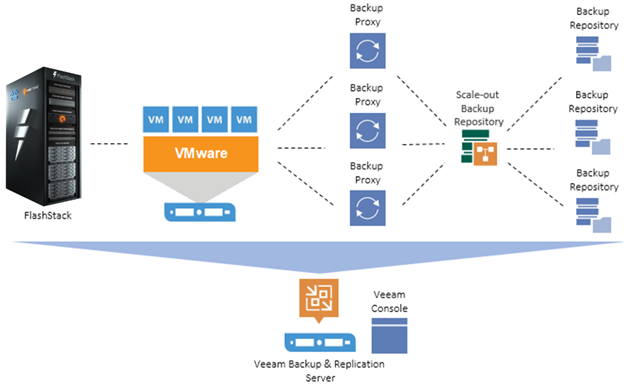
Figure 2 illustrate the high-level Solution Architecture providing protection of FlashStack environment with Veeam v11.
Figure 2. High-level Solution Architecture – FlashStack Data Protection with Veeam
The key features and benefits of the above three backup infrastructure platforms with Veeam are detailed in the following sections.
FlashArray//C: Fast Restores with Storage Efficiency (Dedupe and Compression)
Veeam, with FlashArray//C from Pure Storage, and Cisco UCS C220 M5 servers, delivers maximum flash-based performance that can handle multiple workloads, while paired with Pure Storage data efficiency features. This solution offers storage capacity without compromise, along with flash-based performance at close to disk economics. It targets multiple workloads and large-scale deployments featuring:
● All-QLC flash storage for cost-effective, capacity-oriented workloads
● Advanced data services and technologies for guaranteed data efficiency
● Scale-up, scale-out architecture to meet the capacity expansion requirements of data-intensive workloads
● Non-disruptive, Evergreen architecture that eliminates risky, complex, and costly upgrades
Cisco UCS C240 All Flash Rack Server: Fast Restores and High Backup Throughput
Veeam, with Cisco UCS C240 M5 all-flash storage servers, delivers the performance and flexibility needed to run and support virtually any workload, while meeting the requirements of a sophisticated data protection environment. It features:
● Architectural and compute flexibility
● Multiple workload capability
● Best-in-class backup and restore performance
● Scale-out capability
Cisco UCS S3260 Storage Server: Dense Platform with Optimal Restores and High Backup Throughput
Veeam, with Cisco UCS S3260 M5 storage servers, delivers superior performance with massive scale-up and scale-out capability and disk economics. This solution includes Cisco Intersight or UCS Manager to reduce cost of ownership, simplify management, and deliver consistent policy-based deployments and scalability.
This dense storage platform, combined with FlashStack and Veeam, offers massive storage capacity and high backup throughput for multiple workloads. You can run Veeam components such as Backup Proxy, Veeam Console and Backup Repository on a single compute and storage platform with the ability to scale both compute and storage through Veeam Scale-Out Backup Repositories (SOBR).
You can deploy a scale-out backup storage platform on a cluster of Cisco UCS S3260 storage servers, providing an S3 archive target for the Veeam Capacity tier. The Capacity Tier features Scale-Out Backup Repositories (SOBR) architecture, which makes it possible to immediately copy new backups, and to move older backups to more cost-effective cloud or on-premises object storage. Archiving backup in the Capacity Tier can result in up to 10X savings on long-term data retention costs and help you align with compliance requirements by storing data as long as needed.
Each rack server in the design is redundantly connected to the managing Fabric Interconnects (FI) with two ports to each FI. Ethernet traffic from the upstream network and Fibre Channel frames coming from the FlashArray are converged within the fabric interconnect to be both Ethernet and Fibre Channel over Ethernet and transmitted to the UCS server.
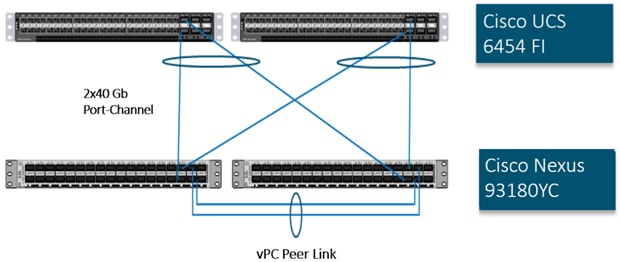
These connections from the 4th Gen UCS 6454 Fabric Interconnect to the Cisco UCS C220, Cisco UCS C240 Rack Server, and Cisco UCS S3260 storage server are detailed in Figure 3.
Figure 3. Compute Connectivity
Each rack and storage server in the design is redundantly connected to the managing fabric interconnects with two ports to each Fabric Interconnect (FI). Ethernet traffic from the upstream network and Fibre Channel frames coming from the FlashArray are converged within the fabric interconnect to be both Ethernet and Fibre Channel over Ethernet and transmitted to the UCS server.
The layer 2 network connection to each Fabric Interconnect is implemented as Virtual Port Channels (vPC) from the upstream Cisco Nexus Switches. In the switching environment, the vPC provides the following benefits:
● Allows a single device to use a Port Channel across two upstream devices
● Eliminates Spanning Tree Protocol blocked ports and use all available uplink bandwidth
● Provides a loop-free topology
● Provides fast convergence if either one of the physical links or a device fails
● Helps ensure high availability of the network
The upstream network switches can connect to the Cisco UCS 6454 Fabric Interconnects using 10G, 25G, 40G, or 100G port speeds. In this design, the 40G ports from the 40/100G ports on the 6454 (1/49-54) were used for the virtual port channels.
Figure 4. Network Connectivity
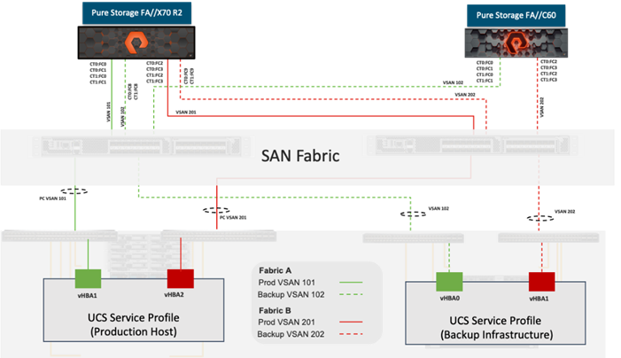
Fibre Channel Storage Connectivity
The Pure Storage FlashArray//X platform and FlashArray//C platform are connected through both MDS 9132Ts to their respective Fabric Interconnects in a traditional air-gapped A/B fabric design. The Fabric Interconnects are configured in N-Port Virtualization (NPV) mode, known as FC end host mode in UCSM. The MDS has N-Port ID Virtualization (NPIV) enabled. This allows F-port channels to be used between the Fabric Interconnect and the MDS, providing the following benefits:
● Increased aggregate bandwidth between the fabric interconnect and the MDS
● Load balancing across the FC uplinks
● High availability in the event of a failure of one or more uplinks
The FlashArray//X platform hosts the source virtual infrastructure and FlashArray//C platform is provisioned with Veeam Backup Repository. Both the platforms share 2xMDS 9132T switches.
Figure 5. Fibre Channel Logical Design
End-to-End Physical Connectivity
The FC end-to-end path in the design is a traditional air-gapped fabric with identical data path through each fabric as detailed below:
● Each Cisco UCS Server is equipped with a Cisco UCS VIC 1400 Series adapter
● Cisco UCS C-Series Rack Servers are equipped with Cisco UCS VIC 1457 and Cisco UCS S-Series Storage server is equipped with a Cisco UCS VIC 1455 providing 2x25Gbe to Fabric Interconnect A and 2x25Gbe to Fabric Interconnect B
● Each Cisco UCS 6454 FI connects to the MDS 9132T for the respective SAN fabric using an F-Port channel
● The Pure Storage FlashArray//X70 R2 and FlashArray//C are connected to both MDS 9132T switches to provide redundant paths through both fabrics
Figure 6. FC End-to-End Data Path
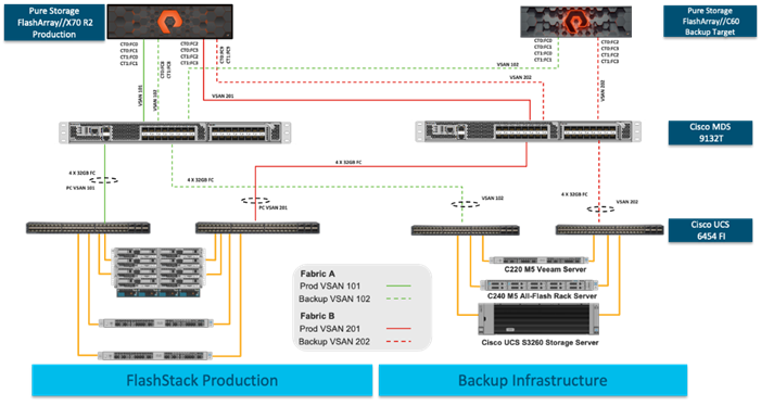
The components of this integrated architecture shown in Figure 6 are:
● Cisco Nexus 93180YC-FX – 10/25/40/100Gbe capable, LAN connectivity to the Cisco UCS compute resources
● Cisco UCS 6454 Fabric Interconnect – Unified management of Cisco UCS compute, and the compute’s access to storage and networks
● Cisco UCS C-Series – High powered rack server, with fast storage
● Cisco UCS S-Series – High powered dense storage platform with two compute nodes
● Cisco MDS 9132T – 32Gb Fibre Channel connectivity within the architecture, as well as interfacing to resources present in an existing data center
● Pure Storage FlashArray//X70 R2 – part of FlashStack environment providing storage for virtual infrastructure hosted on Cisco UCS B Series Server with Cisco UCS 5108 chassis
● Pure Storage FlashArray//C60 – Veeam Backup Repository
● Cisco UCS S3260 Storage server – Veeam Backup Repository
● Cisco UCS C240 All Flash rack server– Veeam Backup Repository
● Cisco UCS C220 rack server – Veeam Backup Server with Veeam Backup Repository on FlashArray//C60
Solution Reference Architecture
Figure 7 illustrates the data protection of FlashStack with Veeam architecture used in this validated design to support fast, reliable, and dense backup targets for virtual infrastructure deployed on FlashStack environment. It follows Cisco configuration requirements to deliver highly available and scalable architecture.
Figure 7. FlashStack Data Protection with Veeam Solution Reference Architecture
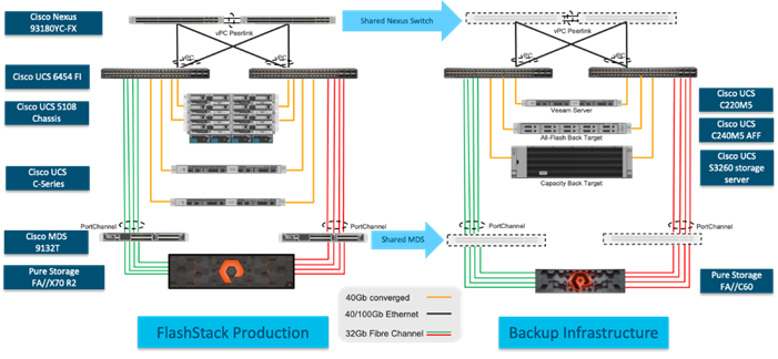
The reference hardware configuration includes:
● Two Cisco Nexus 93180YC-FX switches
● Two Cisco MDS 9132T 32-Gb Fibre Channel switches
● Two Cisco UCS 6454 Fabric Interconnects
● One Cisco UCS 5108 Blade Chassis
● Four Cisco UCS B200 M5 Blade Servers (virtual infrastructure)
● One Cisco UCS C240 M5 All Flash Rack Server providing compute and storage resources for Veeam services
● One Cisco UCS S3260 Storage Server one single compute node providing compute and storage resources for Veeam services
● One Pure Storage FlashArray//X70 R2 (FlashStack environment hosting virtual infrastructure)
● One Pure Storage FlashArray//C providing storage resource for Veeam Backup Repository with Veeam Services running on a Cisco UCS C220 rack server
This document guides you through the detailed steps for deploying the base architecture. This procedure explains everything from physical cabling to network, compute, and storage device configurations.
What is FlashStack?
The FlashStack platform, developed by Cisco and Pure Storage, is a flexible, integrated infrastructure solution that delivers pre-validated storage, networking, and server technologies. Cisco and Pure Storage have carefully validated and verified the FlashStack solution architecture and its many use cases while creating a portfolio of detailed documentation, information, and references to assist customers in transforming their data centers to this shared infrastructure model.
FlashStack is a best practice data center architecture that includes the following components:
● Cisco Unified Computing System
● Cisco Nexus Switches
● Cisco MDS Switches
● Pure Storage FlashArray & FlashBlade
Figure 8. FlashStack Systems Components
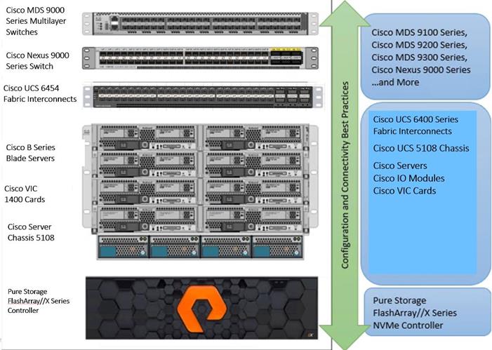
As shown in Figure 8, these components are connected and configured according to best practices of both Cisco and Pure Storage and provide the ideal platform for running a variety of enterprise workloads (for example, databases) with confidence. FlashStack can scale up for greater performance and capacity (adding compute, network, or storage resources individually as needed), or it can scale out for environments that require multiple consistent deployments.
The reference architecture covered in this document leverages the Pure Storage FlashArray//X70 R2 Controller with NVMe based DirectFlash modules for storage, Cisco UCS B200 M5 Blade Server for compute, Cisco Nexus 9000, and Cisco MDS 9100 Series for the switching element and Cisco Fabric Interconnects 6300 Series for system management. As shown in Figure 8, FlashStack architecture can maintain consistency at scale. Each of the component families shown in the FlashStack (Cisco UCS, Cisco Nexus, Cisco MDS, Cisco FI and Pure Storage) offers platform and resource options to scale the infrastructure up or down, while supporting the same features and functionality that are required under the configuration and connectivity best practices of FlashStack.
FlashStack provides a jointly supported solution by Cisco and Pure Storage. Providing a carefully validated architecture built on superior compute, world-class networking, and the leading innovations in all flash storage. The portfolio of validated offerings from FlashStack includes but is not limited to the following:
● Consistent Performance and Scalability
◦ Consistent sub-millisecond latency with 100 percent NVMe enterprise flash storage
◦ Consolidate hundreds of enterprise-class applications in a single rack
◦ Scalability through a design for hundreds of discrete servers and thousands of virtual machines, and the capability to scale I/O bandwidth to match demand without disruption
◦ Repeatable growth through multiple FlashStack CI deployments
● Operational Simplicity
◦ Fully tested, validated, and documented for rapid deployment
◦ Reduced management complexity
◦ No storage tuning or tiers necessary
◦ 3x better data reduction without any performance impact
● Lowest TCO
◦ Dramatic savings in power, cooling, and space with Cisco UCS and 100% flash
◦ Industry leading data reduction
◦ Free FlashArray controller upgrades every three years with Pure’s Evergreen Gold Subscription
● Mission Critical and Enterprise Grade Resiliency
◦ Highly available architecture with no single point of failure
◦ Non-disruptive operations with no downtime
◦ Upgrade and expand without downtime or performance loss
◦ Native data protection capabilities: snapshots and replication
Cisco and Pure Storage have also built a robust and experienced support team focused on FlashStack solutions, from customer account and technical sales representatives to professional services and technical support engineers. The support alliance between Pure Storage and Cisco gives customers and channel services partners direct access to technical experts who collaborate with cross vendors and have access to shared lab resources to resolve potential issues.
This section describes the components used in the solution outlined in this solution.
Cisco Intersight Cloud Based Management
Cisco Intersight is Cisco’s new systems management platform that delivers intuitive computing through cloud-powered intelligence. This platform offers a more intelligent level of management that enables IT organizations to analyze, simplify, and automate their environments in ways that were not possible with prior generations of tools. This capability empowers organizations to achieve significant savings in Total Cost of Ownership (TCO) and to deliver applications faster, so they can support new business initiates. The advantages of the model-based management of the Cisco UCS platform plus Cisco Intersight are extended to Cisco UCS servers.
The Cisco UCS platform uses model-based management to provision servers and the associated storage and fabric automatically, regardless of form factor. Cisco Intersight works in conjunction with Cisco UCS Manager and the Cisco® Integrated Management Controller (IMC). By simply associating a model-based configuration with a resource through service profiles, your IT staff can consistently align policy, server personality, and workloads. These policies can be created once and used repeatedly by IT staff with minimal effort to deploy servers. The result is improved productivity and compliance and lower risk of failures due to inconsistent configuration.
Cisco Intersight is integrated with data center, hybrid cloud platforms, and services to securely deploy and manage infrastructure resources across data center and edge environments. In addition, Cisco will provide future integrations to third-party operations tools to allow customers to use their existing solutions more effectively.
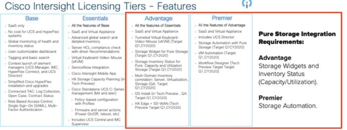
Pure Storage FlashArray with Intersight
The Cisco Intersight Premier edition offers private-cloud Infrastructure-as-a-Service (IaaS) orchestration across Cisco UCS, HyperFlex, and third-party endpoints including VMWare vCenter and Pure Storage. This feature, called Cisco Intersight Orchestrator, enables you to create and execute workflows in Cisco Intersight. For example, provisioning a Pure Storage FlashArray or deploying a new virtual machine from a template could involve multiple tasks, but with Cisco Intersight Orchestrator, the administrator has a workflow designer to visualize a workflow definition and monitor the execution of that workflow on any infrastructure element.
Figure 9. Example of User-Customizable Cisco Intersight Dashboard for Cisco UCS Domain
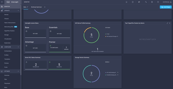
Figure 10. Cisco UCS Manager Device Connector Example
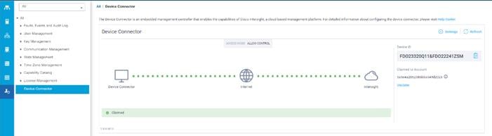
Figure 11. Cisco Intersight License
Cisco Unified Computing System
Cisco UCS Manager (UCSM) provides unified, embedded management of all software and hardware components of the Cisco Unified Computing System™ (Cisco UCS) through an intuitive GUI, a CLI, and an XML API. The manager provides a unified management domain with centralized management capabilities and can control multiple chassis and thousands of virtual machines.
Cisco UCS is a next-generation data center platform that unites computing, networking, and storage access. The platform, optimized for virtual environments, is designed using open industry-standard technologies and aims to reduce total cost of ownership (TCO) and increase business agility. The system integrates a low-latency; lossless 40 Gigabit Ethernet unified network fabric with enterprise-class, x86-architecture servers. It is an integrated, scalable, multi-chassis platform in which all resources participate in a unified management domain.
Cisco Unified Computing System Components
The main components of Cisco UCS are:
● Compute: The system is based on an entirely new class of computing system that incorporates blade servers based on Intel® Xeon® Scalable Family processors.
● Network: The system is integrated on a low-latency, lossless, 25-Gbe unified network fabric. This network foundation consolidates LANs, SANs, and high-performance computing (HPC) networks, which are separate networks today. The unified fabric lowers costs by reducing the number of network adapters, switches, and cables needed, and by decreasing the power and cooling requirements.
● Virtualization: The system unleashes the full potential of virtualization by enhancing the scalability, performance, and operational control of virtual environments. Cisco security, policy enforcement, and diagnostic features are now extended into virtualized environments to better support changing business and IT requirements.
● Storage access: The system provides consolidated access to local storage, SAN storage, and network-attached storage (NAS) over the unified fabric. With storage access unified, Cisco UCS can access storage over Ethernet, Fibre Channel, Fibre Channel over Ethernet (FCoE), and Small Computer System Interface over IP (iSCSI) protocols. This capability provides customers with choices for storage access and investment protection. In addition, server administrators can pre-assign storage-access policies for system connectivity to storage resources, simplifying storage connectivity and management and helping increase productivity.
● Management: Cisco UCS uniquely integrates all system components, enabling the entire solution to be managed as a single entity by Cisco UCS Manager. Cisco UCS Manager has an intuitive GUI, a CLI, and a robust API for managing all system configuration processes and operations.
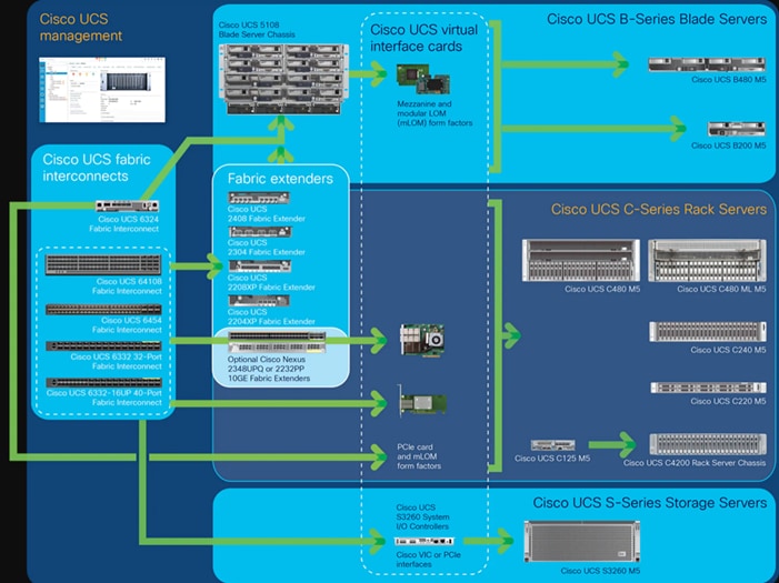
Figure 12. Cisco Data Center Overview
Cisco UCS is designed to deliver the following benefits:
● Reduced TCO and increased business agility
● Increased IT staff productivity through just-in-time provisioning and mobility support
● A cohesive, integrated system that unifies the technology in the data center; the system is managed, serviced, and tested as a whole
● Scalability through a design for hundreds of discrete servers and thousands of virtual machines and the capability to scale I/O bandwidth to match demand
● Industry standards supported by a partner ecosystem of industry leaders
Cisco UCS Manager provides unified, embedded management of all software and hardware components of the Cisco Unified Computing System across multiple chassis, rack servers, and thousands of virtual machines. Cisco UCS Manager manages Cisco UCS as a single entity through an intuitive GUI, a CLI, or an XML API for comprehensive access to all Cisco UCS Manager Functions.
The Cisco UCS 6400 Series Fabric Interconnects are a core part of the Cisco Unified Computing System, providing both network connectivity and management capabilities for the system. The Cisco UCS 6400 Series offer line-rate, low-latency, lossless 10/25/40/100 Gigabit Ethernet, Fibre Channel over Ethernet (FCoE), and Fibre Channel functions.
The Cisco UCS 6400 Series provides the management and communication backbone for the Cisco UCS B-Series Blade Servers, Cisco UCS 5108 B-Series Server Chassis, Cisco UCS Managed C-Series Rack Servers, and Cisco UCS S-Series Storage Servers. All servers attached to a Cisco UCS 6400 Series Fabric Interconnect become part of a single, highly available management domain. In addition, by supporting a unified fabric, Cisco UCS 6400 Series Fabric Interconnect provides both the LAN and SAN connectivity for all servers within its domain.
From a networking perspective, the Cisco UCS 6400 Series use a cut-through architecture, supporting deterministic, low-latency, line-rate 10/25/40/100 Gigabit Ethernet ports, switching capacity of 3.82 Tbps for the 6454, 7.42 Tbps for the 64108, and 200 Gbe bandwidth between the Fabric Interconnect 6400 series and the IOM 2408 per 5108 blade chassis, independent of packet size and enabled services. The product family supports Cisco low-latency, lossless 10/25/40/100 Gigabit Ethernet unified network fabric capabilities, which increase the reliability, efficiency, and scalability of Ethernet networks. The fabric interconnect supports multiple traffic classes over a lossless Ethernet fabric from the server through the fabric interconnect. Significant TCO savings come from an FCoE-optimized server design in which Network Interface Cards (NICs), Host Bus Adapters (HBAs), cables, and switches can be consolidated.
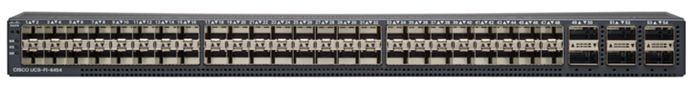
Figure 13. Cisco UCS 6400 Series Fabric Interconnect – 6454 Front View
Figure 14. Cisco UCS 6400 Series Fabric Interconnect – 6454 Rear View
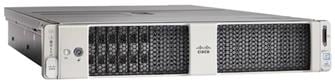
Cisco UCS S3260 Storage Server
The Cisco UCS S3260 Storage Server is a modular, high-density, high-availability dual-node rack server well suited for service providers, enterprises, and industry-specific environments. It addresses the need for dense, cost-effective storage for the ever-growing amounts of data. Designed for a new class of cloud-scale applications and data-intensive workloads, it is simple to deploy and excellent for big data, software-defined storage, and data-protection environments.
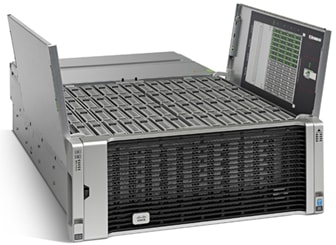
Figure 15. Cisco UCS S3260 Storage Server
The Cisco UCS S3260 server helps you achieve the highest levels of data availability and performance. With dual-node capability that is based on the 2nd Gen Intel® Xeon® Scalable and Intel Xeon Scalable processor, it features up to 840 TB of local storage in a compact 4-Rack-Unit (4RU) form factor. The drives can be configured with enterprise-class Redundant Array of Independent Disks (RAID) redundancy or with a pass-through Host Bus Adapter (HBA) controller. Network connectivity is provided with dual-port 40-Gbps nodes in each server, with expanded unified I/O capabilities for data migration between Network-Attached Storage (NAS) and SAN environments. This storage-optimized server comfortably fits in a standard 32-inch-depth rack, such as the Cisco® R 42610 Rack.
You can deploy Cisco UCS S-Series Storage Servers as standalone servers or as part of a Cisco UCS managed environment to take advantage of Cisco® standards-based unified computing innovations that can help reduce your TCO and increase your business agility.
The Cisco UCS S3260 uses a modular server architecture that, using Cisco’s blade technology expertise, allows you to upgrade the computing or network nodes in the system without the need to migrate data from one system to another. It delivers the following:
● Dual 2-socket server nodes based on 2nd Gen Intel Xeon Scalable and Intel Xeon Scalable processors with up to 48 cores per server node
● Up to 1.5 TB of DDR4 memory per M5 server node and up to 1 TB of Intel Optane™ DC Persistent Memory
● Support for high-performance Nonvolatile Memory Express (NVMe) and flash memory
● Massive 840-TB data storage capacity that easily scales to petabytes with Cisco UCS Manager software
● Policy-based storage management framework for zero-touch capacity on demand
● Dual-port 40-Gbps system I/O controllers with a Cisco UCS Virtual Interface Card 1300 platform embedded chip or PCIe-based system I/O controller for Quad Port 10/25G Cisco VIC 1455 or Dual Port 100G Cisco VIC 1495
● Unified I/O for Ethernet or Fibre Channel to existing NAS or SAN storage environments
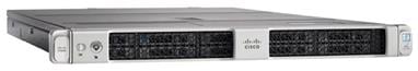
Cisco UCS C240 All Flash Rack Server
The Cisco UCS C240 M5 Rack Server is a 2-socket, 2-Rack-Unit (2RU) rack server offering industry-leading performance and expandability. It supports a wide range of storage and I/O-intensive infrastructure workloads, from big data and analytics to collaboration. Cisco UCS C-Series Rack Servers can be deployed as standalone servers or as part of a Cisco Unified Computing System™ (Cisco UCS) managed environment to take advantage of Cisco’s standards-based unified computing innovations that help reduce customers’ Total Cost of Ownership (TCO) and increase their business agility.
Figure 16. Cisco UCS C240 SFF Rack Server (All Flash)
In response to ever-increasing computing and data-intensive real-time workloads, the enterprise-class Cisco UCS C240 M5 server extends the capabilities of the Cisco UCS portfolio in a 2RU form factor. It incorporates the Intel® Xeon® Scalable processors, supporting up to 20 percent more cores per socket, twice the memory capacity, and five times more.
Non-Volatile Memory Express (NVMe) PCI Express (PCIe) Solid-State Disks (SSDs) compared to the previous generation of servers. These improvements deliver significant performance and efficiency gains that will improve your application performance. The Cisco UCS C240 M5 delivers outstanding levels of storage expandability with exceptional performance, with:
The latest second-generation Intel Xeon Scalable CPUs, with up to 28 cores per socket, provide the following:
● Supports the first-generation Intel Xeon Scalable CPU, with up to 28 cores per socket
● Support for the Intel Optane DC Persistent Memory (128G, 256G, 512G)[1]
● Up to 24 DDR4 DIMMs for improved performance including higher density DDR4 DIMMs
● Up to 26 x 2.5-inch SAS and SATA HDDs and SSDs and up to 4 NVMe PCIe drives
● Support for 12-Gbps SAS modular RAID controller in a dedicated slot, leaving the remaining PCIe Generation 3.0 slots available for other expansion cards
● Modular LAN-On-Motherboard (mLOM) slot that can be used to install a Cisco UCS Virtual Interface Card (VIC) without consuming a PCIe slot, supporting dual 10- or 40-Gbps network connectivity
● Dual embedded Intel x550 10GBASE-T LAN-On-Motherboard (LOM) ports
● Modular M.2 or Secure Digital (SD) cards that can be used for boot
Cisco UCS C220 SFF Rack Server
The Cisco UCS C220 M5 Rack Server is among the most versatile general-purpose enterprise infrastructure and application servers in the industry. It is a high-density 2-socket rack server that delivers industry-leading performance and efficiency for a wide range of workloads, including virtualization, collaboration, and bare-metal applications. The Cisco UCS C-Series Rack Servers can be deployed as standalone servers or as part of the Cisco Unified Computing System™ (Cisco UCS) to take advantage of Cisco’s standards-based unified computing innovations that help reduce customers’ Total Cost of Ownership (TCO) and increase their business agility.
Figure 17. Cisco UCS C220 SFF Rack Server
The Cisco UCS C220 M5 server extends the capabilities of the Cisco UCS portfolio in a 1-Rack-Unit (1RU) form factor. It incorporates the Intel® Xeon® Scalable processors, supporting up to 20 percent more cores per socket, twice the memory capacity, 20 percent greater storage density, and five times more PCIe NVMe Solid-State Disks (SSDs) compared to the previous generation of servers. These improvements deliver significant performance and efficiency gains that will improve your application performance. The Cisco UCS C220 M5 delivers outstanding levels of expandability and performance in a compact package, with:
● Latest (second generation) Intel Xeon Scalable CPUs with up to 28 cores per socket
● Supports first-generation Intel Xeon Scalable CPUs with up to 28 cores per socket
● Up to 24 DDR4 DIMMs for improved performance
● Support for the Intel Optane DC Persistent Memory (128G, 256G, 512G)
● Up to 10 Small-Form-Factor (SFF) 2.5-inch drives or 4 Large-Form-Factor (LFF) 3.5-inch drives (77 TB storage capacity with all NVMe PCIe SSDs)
● Support for 12-Gbps SAS modular RAID controller in a dedicated slot, leaving the remaining PCIe Generation 3.0 slots available for other expansion cards
● Modular LAN-On-Motherboard (mLOM) slot that can be used to install a Cisco UCS Virtual Interface Card (VIC) without consuming a PCIe slot
● Dual embedded Intel x550 10GBASE-T LAN-On-Motherboard (LOM) ports
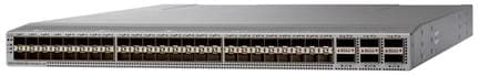
Cisco Nexus 93180YC-FX Switches
The 93180YC-EX Switch provides a flexible line-rate Layer 2 and Layer 3 feature set in a compact form factor. Designed with Cisco Cloud Scale technology, it supports highly scalable cloud architectures. With the option to operate in Cisco NX-OS or Application Centric Infrastructure (ACI) mode, it can be deployed across enterprise, service provider, and Web 2.0 data centers, and provides the following:
● Architectural Flexibility
◦ Includes top-of-rack or middle-of-row fiber-based server access connectivity for traditional and leaf-spine architectures
◦ Leaf node support for Cisco ACI architecture is provided in the roadmap
◦ Increase scale and simplify management through Cisco Nexus 2000 Fabric Extender support
● Feature Rich
◦ Enhanced Cisco NX-OS Software is designed for performance, resiliency, scalability, manageability, and programmability
◦ ACI-ready infrastructure helps users take advantage of automated policy-based systems management
◦ Virtual Extensible LAN (VXLAN) routing provides network services
◦ Rich traffic flow telemetry with line-rate data collection
◦ Real-time buffer utilization per port and per queue, for monitoring traffic micro-bursts and application traffic patterns
● Highly Available and Efficient Design
◦ High-density, non-blocking architecture
◦ Easily deployed into either a hot-aisle and cold-aisle configuration
◦ Redundant, hot-swappable power supplies and fan trays
● Simplified Operations
◦ Power-On Auto Provisioning (POAP) support allows for simplified software upgrades and configuration file installation
◦ An intelligent API offers switch management through remote procedure calls (RPCs, JSON, or XML) over a HTTP/HTTPS infrastructure
◦ Python Scripting for programmatic access to the switch command-line interface (CLI)
◦ Hot and cold patching, and online diagnostics
● Investment Protection
A Cisco 40 Gbe bidirectional transceiver allows reuse of an existing 10 Gigabit Ethernet multimode cabling plant for 40 Gigabit Ethernet Support for 1 Gbe and 10 Gbe access connectivity for data centers migrating access switching infrastructure to faster speed. The following are supported:
● 1.8 Tbps of bandwidth in a 1 RU form factor
● 48 fixed 1/10/25-Gbe SFP+ ports
● 6 fixed 40/100-Gbe QSFP+ for uplink connectivity
● Latency of less than 2 microseconds
● Front-to-back or back-to-front airflow configurations
● 1+1 redundant hot-swappable 80 Plus Platinum-certified power supplies
● Hot swappable 3+1 redundant fan trays
Figure 18. Cisco Nexus 93180YC-EX Switch
Cisco MDS 9132T 32-Gb Fiber Channel Switch
The next-generation Cisco® MDS 9132T 32-Gb 32-Port Fibre Channel Switch (Figure 19) provides high-speed Fibre Channel connectivity from the server rack to the SAN core. It empowers small, midsize, and large enterprises that are rapidly deploying cloud-scale applications using extremely dense virtualized servers, providing the dual benefits of greater bandwidth and consolidation.
Small-scale SAN architectures can be built from the foundation using this low-cost, low-power, non-blocking, line-rate, and low-latency, bi-directional airflow capable, fixed standalone SAN switch connecting both storage and host ports.
Medium-size to large-scale SAN architectures built with SAN core directors can expand 32-Gb connectivity to the server rack using these switches either in switch mode or Network Port Virtualization (NPV) mode.
Additionally, investing in this switch for the lower-speed (4- or 8- or 16-Gb) server rack gives you the option to upgrade to 32-Gb server connectivity in the future using the 32-Gb Host Bus Adapter (HBA) that are available today. The Cisco® MDS 9132T 32-Gb 32-Port Fibre Channel switch also provides unmatched flexibility through a unique port expansion module (Figure 19) that provides a robust cost-effective, field swappable, port upgrade option.
This switch also offers state-of-the-art SAN analytics and telemetry capabilities that have been built into this next-generation hardware platform. This new state-of-the-art technology couples the next-generation port ASIC with a fully dedicated Network Processing Unit designed to complete analytics calculations in real time. The telemetry data extracted from the inspection of the frame headers are calculated on board (within the switch) and, using an industry-leading open format, can be streamed to any analytics-visualization platform. This switch also includes a dedicated 10/100/1000BASE-T telemetry port to maximize data delivery to any telemetry receiver including Cisco Data Center Network Manager.
Figure 19. Cisco 9132T 32-Gb MDS Fibre Channel Switch
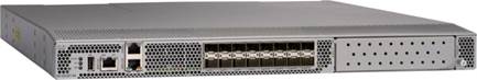
Figure 20. Cisco MDS 9132T 32-Gb 16-Port Fibre Channel Port Expansion Module
● Features
◦ High performance: MDS 9132T architecture, with chip-integrated nonblocking arbitration, provides consistent 32-Gb low-latency performance across all traffic conditions for every Fibre Channel port on the switch.
◦ Capital Expenditure (CapEx) savings: The 32-Gb ports allow users to deploy them on existing 16- or 8-Gb transceivers, reducing initial CapEx with an option to upgrade to 32-Gb transceivers and adapters in the future.
◦ High availability: MDS 9132T switches continue to provide the same outstanding availability and reliability as the previous-generation Cisco MDS 9000 Family switches by providing optional redundancy on all major components such as the power supply and fan. Dual power supplies also facilitate redundant power grids.
◦ Pay-as-you-grow: The MDS 9132T Fibre Channel switch provides an option to deploy as few as eight 32-Gb Fibre Channel ports in the entry-level variant, which can grow by 8 ports to 16 ports, and thereafter with a port expansion module with sixteen 32-Gb ports, to up to 32 ports. This approach results in lower initial investment and power consumption for entry-level configurations of up to 16 ports compared to a fully loaded switch. Upgrading through an expansion module also reduces the overhead of managing multiple instances of port activation licenses on the switch. This unique combination of port upgrade options allow four possible configurations of 8 ports, 16 ports, 24 ports and 32 ports.
◦ Next-generation Application-Specific Integrated Circuit (ASIC): The MDS 9132T Fibre Channel switch is powered by the same high-performance 32-Gb Cisco ASIC with an integrated network processor that powers the Cisco MDS 9700 48-Port 32-Gb Fibre Channel Switching Module. Among all the advanced features that this ASIC enables, one of the most notable is inspection of Fibre Channel and Small Computer System Interface (SCSI) headers at wire speed on every flow in the smallest form-factor Fibre Channel switch without the need for any external taps or appliances. The recorded flows can be analyzed on the switch and also exported using a dedicated 10/100/1000BASE-T port for telemetry and analytics purposes.
◦ Intelligent network services: Slow-drain detection and isolation, VSAN technology, Access Control Lists (ACLs) for hardware-based intelligent frame processing, smartzoning and fabric wide Quality of Service (QoS) enable migration from SAN islands to enterprise-wide storage networks. Traffic encryption is optionally available to meet stringent security requirements.
◦ Sophisticated diagnostics: The MDS 9132T provides intelligent diagnostics tools such as Inter-Switch Link (ISL) diagnostics, read diagnostic parameters, protocol decoding, network analysis tools, and integrated Cisco Call Home capability for greater reliability, faster problem resolution, and reduced service costs.
◦ Virtual machine awareness: The MDS 9132T provides visibility into all virtual machines logged into the fabric. This feature is available through HBAs capable of priority tagging the Virtual Machine Identifier (VMID) on every FC frame. Virtual machine awareness can be extended to intelligent fabric services such as analytics[1] to visualize performance of every flow originating from each virtual machine in the fabric.
◦ Programmable fabric: The MDS 9132T provides powerful Representational State Transfer (REST) and Cisco NX-API capabilities to enable flexible and rapid programming of utilities for the SAN as well as polling point-in-time telemetry data from any external tool.
◦ Single-pane management: The MDS 9132T can be provisioned, managed, monitored, and troubleshot using Cisco Data Center Network Manager (DCNM), which currently manages the entire suite of Cisco data center products.
◦ Self-contained advanced anticounterfeiting technology: The MDS 9132T uses on-board hardware that protects the entire system from malicious attacks by securing access to critical components such as the bootloader, system image loader and Joint Test Action Group (JTAG) interface.
Pure Storage acquired Compuverde in 2019, and they’ve been integrating this technology into the Purity//FA operating system. They emphasize “integrating”, because they incorporated key parts of it into Purity to give you the advantages of native files alongside blocks.
The SMB and NFS protocols bring consolidated storage to the Purity//FA operating system, complementing its block capabilities, while the file system offers features like directory snapshots and directory-level performance and space monitoring.
Moreover, Purity includes enterprise-grade data security, modern data protection options, and complete business continuity and global disaster recovery through ActiveCluster multi-site stretch cluster and ActiveDR* for continuous replication with near zero RPO. All these features are included with every array.
Figure 21. FlashArray//C Specifications
Table 1. FlashArray Connectivity (Applicable for both FA//X and FA//C)
| ONBOARD PARTS (PER CONTROLLER) |
HOST I/O CARDS (3 SLOTS/CONTROLLER) |
|
| 2 x 1/10/25Gb Ethernet 2 x 1/10/25Gb Ethernet Replication 2 x 1Gb Management Ports |
2-port 10GBase-T Ethernet 2-port 1/10/25Gb Ethernet 2-port 40Gb Ethernet 2-port 25/100Gb NVMe/RoCE |
2-port 16/32Gb SCSI FC and NVMe-FC 4-port 16/32Gb SCSI FC and NVMe-FC |
Customers can deploy storage once and enjoy a subscription to continuous innovation through Pure’s Evergreen Storage ownership model: expand and improve performance, capacity, density, and/or features for 10 years or more – all without downtime, performance impact, or data migrations. Pure has disrupted the industry’s 3-5-year rip-and-replace cycle by engineering compatibility for future technologies right into its products, notably nondisruptive capability to upgrade from //M to //X with NVMe, DirectMemory, and NVMe-oF capability.
Pure1, a cloud-based management, analytics, and support platform, expands the self-managing, plug-n-play design of Pure all-flash arrays with the machine learning predictive analytics and continuous scanning of Pure1 Meta™ to enable an effortless, worry-free data platform.
In the Cloud IT operating model, installing, and deploying management software is an oxymoron: you simply login. Pure1 Manage is SaaS-based, allowing you to manage your array from any browser or from the Pure1 Mobile App – with nothing extra to purchase, deploy, or maintain. From a single dashboard you can manage all your arrays, with full visibility on the health and performance of your storage.
Pure1 Analyze delivers true performance forecasting – giving customers complete visibility into the performance and capacity needs of their arrays – now and in the future. Performance forecasting enables intelligent consolidation and unprecedented workload optimization.
Pure combines an ultra-proactive support team with the predictive intelligence of Pure1 Meta to deliver unrivaled support that’s a key component in our proven FlashArray 99.9999% availability. Customers are often surprised and delighted when we fix issues they did not even know existed.
The foundation of Pure1 services, Pure1 Meta is global intelligence built from a massive collection of storage array health and performance data. By continuously scanning call-home telemetry from Pure’s installed base, Pure1 Meta uses machine learning predictive analytics to help resolve potential issues and optimize workloads. The result is both a white glove customer support experience and breakthrough capabilities like accurate performance forecasting.
Meta is always expanding and refining what it knows about array performance and health, moving the Data Platform toward a future of self-driving storage.
Pure1 helps you narrow down the troubleshooting steps in your virtualized environment. VM Analytics provides you with a visual representation of the IO path from the VM all the way through to the FlashArray. Other tools and features guide you through identifying where an issue might be occurring in order to help eliminate potential candidates for a problem.
VM Analytics doesn’t only help when there’s a problem. The visualization allows you to identify which volumes and arrays particular applications are running on. This brings the whole environment into a more manageable domain.
Veeam Backup & Replication is a 4-in-1 solution combining backup, replication, storage snapshots, and Continuous Data Protection (CDP) under a single platform, delivering faster and more flexible data protection, recovery, and retention options. Veeam Backup & Replication can protect all enterprise workloads, including virtual, physical, cloud, and file for organizations operating out of their own data centers, public cloud, managed cloud, or any combination.
For this CVD, Veeam Backup & Replication was configured to protect VMware virtual machines (VMs) running on FlashStack. When protecting VMs, Veeam Backup & Replication operates at the virtualization layer and uses an image-based approach for VM backup. When backup jobs are run, Veeam retrieves the VM data leveraging two things. First, the VMware API for Data Protection (VADP). Second, Veeam storage snapshot integration with the Pure Storage FlashArray//X that provides the storage for the FlashStack environment. Veeam Backup & Replication leverages a vSphere snapshot for point-in-time backup and application-aware processing. Once Veeam creates the application-aware VMware snapshot, it then orchestrates a transactionally consistent storage snapshot on the Pure Storage FlashArray//X. Veeam then removes the VMware snapshot to minimize the impact of backup on the production virtual workloads and backs up the data from the FlashArray//X storage snapshot over the storage network (for example, Fibre Channel or iSCSI).
Veeam Backup & Replication creates image-based backups that can be used for all types of recovery, including:
● Instant VM Recovery enables you to instantly start a VM directly from a backup file
● Application-Item Recovery leverages Veeam Explorers to enable granular restore of application-specific items
● Full VM recovery enables you to recover a VM from a backup file to its original, or another, location
● VM file recovery enables you to recover separate VM files (for example, virtual disks, configuration files)
● Instant VM Disk Recovery enables you to recover a specific hard drive of a VM from the backup file and attach it to the original VM, or a new VM
● Windows file-level recovery enables you to recover individual Windows guest OS files (from FAT, NTFS, and ReFS file systems)
● Multi-OS file-level recovery enables you to recover files from 15 different guest OS file systems
Veeam Backup & Replication uses the same image-level backup for all data recovery operations. You can restore VMs, VM files and drives, application objects, and individual guest OS files to the most recent state or any available restore point.
In addition to being able to provide these capabilities from backup files, Veeam Backup & Replication can also provide many of these recoveries from Veeam orchestrated storage snapshots on the FlashStack.
Veeam Explorers are powerful recovery tools included in Veeam Backup & Replication. Customers can restore granular application items, directly from Veeam backups or orchestrated storage snapshots. Veeam has application-specific Explorers for the following enterprise applications:
● Microsoft Active Directory: Search and restore all Active Directory object types (e.g., users, groups, computer accounts, contacts, expiring links), Group Policy Objects (GPOs), Active Directory-integrated Microsoft DNS records, and Configuration Partition objects.
● Microsoft Exchange: Get instant visibility into Exchange backups, advanced search capabilities, and quick recovery of individual Exchange items (for example, emails, contacts, notes), online archive mailboxes, purges folder support, and hard-deleted (such as permanently deleted) items; eDiscovery features include detailed export reports and export size estimation based on query search criteria.
● Microsoft SharePoint: Get instant visibility into SharePoint backups, search for and quickly restore full SharePoint sites, item permissions, and specific files. Export recovered items directly to their original SharePoint server or send them as an email attachment.
● Microsoft SQL Server: Get fast transaction and table-level recovery of SQL databases, including agentless transaction log backup and replay, so you can restore your SQL databases to a precise point in time and achieve low Recovery Time and Point Objectives (RTPO).
● Oracle: Get transaction-level recovery of Oracle databases including agentless transaction log backup, so you can restore your Oracle databases to a precise point in time, self-service restore, and restore via PowerShell.
![]() Each Explorer has a corresponding user guide.
Each Explorer has a corresponding user guide.
With instant VM recovery, you can immediately restore a VM into your production environment by running it directly from the backup file. Instant VM recovery helps improve recovery time objectives (RTO), minimize disruption and downtime of production VMs. It is like having a "temporary spare" for a VM; users remain productive while you can troubleshoot an issue with the failed VM.
When instant VM recovery is performed, Veeam Backup & Replication uses the Veeam vPower technology to mount a VM image to an ESX(i) host directly from a compressed and deduplicated backup file. Since there is no need to extract the VM from the backup file and copy it to production storage, you can restart a VM from any restore point (incremental or full) in a matter of minutes.
After the VM is back online you can use VMware storage vMotion to migrate the VM back to production storage.
Veeam Backup & Replication can help you to restore specific VM files (for example, vmdk, vmx) if any of these files are deleted or the datastore is corrupted. This option provides a great alternative to full VM restore, for example, when your VM configuration file is missing, and you need to restore it. Instead of restoring the whole VM image to the production storage, you can restore the specific VM file only. Another data recovery option provided by Veeam Backup & Replication is restore of a specific hard drive of a VM. If a VM hard drive becomes corrupted for some reason (for example, with a virus), you can restore it from the image-based backup to any good-to-know point in time.
Continuous Data Protection (CDP)
Eliminate downtime and minimize data loss for Tier-1 VMware vSphere workloads and perform immediate recoveries to the latest state or desired point in time with the built-in CDP functionality, achieving the most stringent RTOs and RPOs.
Veeam CDP implementations include:
● No VM snapshots — Veeam CDP captures all write I/O directly in the data path with the VMware-certified I/O filter driver, eliminating the need to create VM snapshots as with classic replication jobs. And with I/O-level tracking, only the data changed is sent over to a DR site, as opposed to larger virtual disk blocks returned by the changed block tracking.
● No workload or hardware dependency — Protect any OS and applications that can run within a vSphere VM. And unlike storage-based replication, Veeam CDP works across all types of storage arrays, hyperconverged storage solutions, and even local vSphere ESXi storage.
● Asynchronous replication — Unlike synchronous array-based replication, Veeam CDP can be used across any distance while requiring significantly lower bandwidth, thanks to I/O consolidation, when the same block is overwritten multiple times, and network traffic compression.
● Policy-based protection — Unlike with regular replication jobs, you don’t have to worry about scheduling at all. Just define the required RPO (maximum data loss allowed in case of a disaster) and the CDP policy will take care of performing the sync cycles as needed. Also, to reduce monitoring events spam, you can define acceptable RPO violation thresholds so that sporadic connectivity issues do not result in alarms.
● Flexible retention — Separately define short-term retention, allowing crash-consistent restores to a point in time with RPO period granularity, and long-term retention policy with optional periodic application-consistent restore points providing an additional layer of protection.
● Flexible deployment models — Depending on the amount of data under protection, you can opt for virtual CDP proxies or use dedicated physical CDP proxies to completely offload all data processing overhead from your vSphere hosts, removing impact to your VM consolidation ratio. In either case, only one proxy per vSphere cluster is required with additional proxies providing redundancy and increased scalability.
● Deployment assistant — A built-in deployment calculator removes the guesswork by looking at the historical I/O of all VMs selected for protection in the CDP policy to estimate required bandwidth to achieve the specified RPO and evaluates whether your currently selected CDP proxy resources are sufficient for the historical I/O change rate.
● No additional licensing — Veeam CDP is included in the Veeam Universal License along with existing data protection methods for vSphere VMs: host-based backup or replication, agent-based backup, application-level backup, and storage snapshots. And just as before, using multiple protection methods on the same VM does not consume additional licenses.
![]() Veeam CDP functionality requires deploying the I/O filter to both the source and target vSphere cluster. This can be done by right-clicking the cluster in the newly added clusters tree view on the Backup Infrastructure tab.
Veeam CDP functionality requires deploying the I/O filter to both the source and target vSphere cluster. This can be done by right-clicking the cluster in the newly added clusters tree view on the Backup Infrastructure tab.
Veeam Replication can be used for workloads that require RPOs better than recovery from backup, but not the near-zero RPOs of Veeam CDP. Veeam Replication complements image-based backup and CDP with image-based replication. Replication is the process of copying a VM from its primary location (source host) to a destination location (target host). Veeam Backup & Replication creates an exact copy of the VM (replica), registers it on the target host, and maintains it in sync with the original VM.
Replication provides tier-2 recovery time objectives (RTOs) and recovery point objectives (RPOs). Veeam Backup & Replication provides the means to perform both onsite replication for high availability (HA) scenarios and remote (offsite) replication for disaster recovery (DR) scenarios. To facilitate replication over WAN or slower connections, Veeam Backup & Replication optimizes traffic transmission, by filtering out unnecessary data blocks (such as duplicate data blocks, zero data blocks, or blocks of swap files) and compresses replica traffic. Veeam Backup & Replication also allows you to apply network throttling rules to prevent replication jobs from consuming the entire bandwidth available in your environment.
WAN accelerators are optional components in the Veeam infrastructure. You can use WAN accelerators if you replicate VMs or send Backup Copies over a slow connection or over the WAN.
In the replication and Backup Copy process, WAN accelerators are responsible for global data caching and deduplication. To use WAN acceleration, you must deploy two WAN accelerators in the following manner:
● The source WAN accelerator must be deployed on the source side, close to the Veeam Backup Proxy running the source-side Data Mover Service.
● The target WAN accelerator must be deployed in the target side, close to the Veeam Backup Proxy running the target-side Data Mover Service.
In case of software or hardware malfunction, you can quickly recover a corrupted VM by failing over to its replica. When you perform failover, a replicated VM takes over the role of the original VM. You can fail over to the latest state of a replica or to any of its good known restore points.
In Veeam Backup & Replication, failover is a temporary intermediate step that should be further finalized. Veeam Backup & Replication offers the following options for different disaster recovery scenarios:
· You can perform permanent failover to leave the workload on the target host and let the replica VM act as the original VM. Permanent failover is suitable if the source and target hosts are nearly equal in terms of resources and are located on the same HA site.
· You can perform failback to recover the original VM on the source host or in a new location. Failback is used in case you failed over to a DR site that is not intended for continuous operations and would like to move the operations back to the production site when the consequences of a disaster are eliminated.
Veeam Backup & Replication supports failover and failback operations for one VM and for several VMs. In case one or several hosts fail, you can use failover plans to restore operations with minimum downtime.
Failover-Plans
If you have several VMs running interdependent applications, you need to failover them one by one, as a group. To do this automatically, you can prepare a failover plan.
In a failover plan, you set the order in which VMs must be processed and time delays for VMs. The time delay is an interval of time for which Veeam Backup & Replication must wait before starting the failover operation for the next VM in the list. It helps to ensure that some VMs, such as a DNS server, is already running at the time the dependent VMs start. The failover plan must be created in advance. In case the primary VM group goes offline, you can start the corresponding failover plan manually. When you start the procedure, you can choose to fail over to the latest state of a VM replica or to any of its good known restore points.
Planned Failover
If you know that your primary VMs are about to go offline, you can proactively switch the workload to their replicas. A planned failover is smooth manual switching from a primary VM to its replica with minimum interruption in operation. You can use the planned failover, for example, if you plan to perform datacenter migration, maintenance, or software upgrade of the primary VMs. You can also perform planned failover if you have advance notice of a disaster approaching (for example, Hurricane) that will require taking the primary servers offline.
Failback
If you want to resume operation of a production VM, you can fail back to it from a VM replica. When you perform failback, you get back from the VM replica to the original VM, shift your I/O and processes from the target host to the production host and return to the normal operation mode.
If you managed to restore operation of the source host, you can switch from the VM replica to the original VM on the source host. If the source host is not available, you can restore the original VM to a new location and switch back to it.
Veeam Availability Suite
Veeam Availability Suite combines the backup, replication, storage snapshots, and CDP capabilities of Veeam Backup & Replication with the advanced monitoring, reporting, and capacity planning functionality of Veeam ONE. Veeam Availability Suite delivers everything you need to reliably protect and manage your Cisco FlashStack virtual environment. Veeam Backup & Replication is a modular solution that lets you build a scalable backup infrastructure for environments of different sizes and configurations. The installation package of Veeam Backup & Replication includes a set of components that you can use to configure the backup infrastructure. Some components are mandatory and provide core functionality; some components are optional and can be installed to provide additional functionality for your business and deployment needs. You can co-install all Veeam Backup & Replication components on the same machine, physical or virtual, or you can set them up separately for a more scalable approach
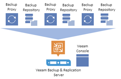
Figure 22 shows an overview on the main Veeam components.
Figure 22. Veeam Backup & Replication Components
Backup Server
The Veeam Backup Server can run on a Windows-based physical or virtual machine on which Veeam Backup & Replication is installed. It is the core component in the backup infrastructure that fills the role of the “configuration and control center.” The backup server performs all types of administrative activities:
● Coordinate’s backup, storage snapshots, CDP, replication, recovery verification, and restore tasks
● Controls job scheduling and resource allocation
● Manages all Backup Proxy and Backup Repository servers and other components of the backup infrastructure
The Veeam Backup Server is used to set up and manage backup infrastructure components as well as specify global settings for the backup infrastructure.
Figure 23. Veeam Backup Server Management
In addition to its primary functions, a newly deployed backup server also performs the roles of the default Backup Proxy and the Backup Repository.
The backup server uses the following services and components:
● Veeam Backup Service is a Windows service that coordinates all operations performed by Veeam Backup & Replication such as backup, storage snapshots, CDP, replication, recovery verification and restore tasks. The Veeam Backup Service runs under the Local System account or account that has the Local Administrator permissions on the backup server.
● Veeam Backup Shell provides the application user interface and allows user access to the application's functionality.
● Veeam Guest Catalog Service is a Windows service that manages guest OS file system indexing for VMs and replicates system index data files to enable search through guest OS files. Index data is stored in the Veeam Backup Catalog — a folder on the backup server. The Veeam Guest Catalog Service running on the backup server works in conjunction with search components installed on Veeam Backup Enterprise Manager and (optionally) a dedicated Microsoft Search Server.
● Veeam Backup SQL Database is used by Veeam Backup Service, Veeam Backup Shell, and Veeam Guest Catalog Service to store data about the backup infrastructure, jobs, sessions, and so on. The database instance can be located on a SQL Server installed either locally (on the same machine where the backup server is running) or remotely.
● Backup Proxy Services. In addition to dedicated services, the backup server runs a set of data mover services.
Backup Proxy
The Backup Proxy is an architecture component that sits between the data source and backup target and is used to process jobs and deliver backup traffic. In particular, the Backup Proxy tasks include retrieving VM data from the production storage, optionally compressing, deduplicating, and encrypting the data, then sending it to the Backup Repository (for example, if you run a backup job) or to another Backup Proxy (for example, if you run a replication job). As the data handling task is assigned to the Backup Proxy, the backup server becomes the “point of control” for dispatching jobs to Backup Proxy servers.
The role of a Backup Proxy can be assigned to a Windows or Linux server (physical or virtual) in your environment. You can deploy Backup Proxies both in the primary site and in remote sites. To optimize performance of several concurrent jobs, you can scale-out to use multiple Backup Proxies. In this case, Veeam Backup & Replication will distribute the backup workload between available Backup Proxies.
Figure 24. Veeam Distributed Proxy Server Deployment
Using Veeam Backup Proxies lets you easily scale your backup infrastructure up and down based on your demands. Backup Proxies run light-weight services that take a few seconds to deploy from the Veeam console. The primary role of the Backup Proxy is to provide an optimal route for backup traffic and enable efficient data transfer.
The Veeam Backup Proxy uses the Veeam Data Mover Service is responsible for deploying and coordinating executable modules that act as "data movers" and perform main job activities on behalf of Veeam Backup & Replication, such as communicating with VMware Tools, copying VM files, performing data deduplication and compression and so on.
Backup Repository
A Backup Repository is a location used by Veeam Backup & Replication jobs to store backup files and metadata for replicated VMs.
You can configure one of the following types of Backup Repositories:
● Microsoft Windows server with local or directly attached storage. The storage can be a local disk, directly attached disk-based storage (such as a USB hard drive), or iSCSI/FC SAN LUN in case the server is connected to the SAN fabric.
● Linux server with local, directly attached storage, SAN storage or mounted NFS. The storage can be a local disk, directly attached disk-based storage (such as a USB hard drive), NFS share, or iSCSI/FC SAN LUN in case the server is connected to the SAN fabric.
● Hardened backup repository is a Linux-based backup repository with an option for switching on native Linux immutability. Immutability protects your data from loss as a result of malware activity by temporarily prohibiting the deletion of data.
● CIFS (SMB) share. SMB share cannot host Veeam Data Mover Services. For this reason, data to the SMB share is written from the gateway server. By default, this role is performed by a Backup Proxy that is used by the job for data transport.
● NFS share. NFS share cannot host Veeam Data Mover Services. For this reason, data to the NFS share is written from the gateway server. By default, this role is performed by a Backup Proxy that is used by the job for data transport.
● Deduplicating storage appliance. Veeam Backup & Replication supports different deduplicating storage appliances.
Scale-Out Backup Repository
A scale-Out Backup Repository is a repository system with horizontal scaling support for multi-tier storage of data. The Scale-Out Backup Repository consists of one or more Backup Repositories called the performance tier and can be expanded with object storage repositories for long-term and archive storage: capacity tier and archive tier. All the storage devices and systems inside the Scale-Out Backup Repository are joined into a system.
The main capabilities of Scale-Out Backup Repositories are:
● It provides a convenient way of managing the backup storage.
● The Scale-Out Backup Repository can be expanded at any moment: if the performance extents of your Scale-Out Backup Repository run out of space, you can add a new performance extent to the existing Scale-Out Backup Repository. The free space on this storage system will be added to the capacity of the Scale-Out Backup Repository. As a result, you will not have to move backups to a backup repository of a larger size.
● It supports any backup target supported by Veeam: Windows or Linux servers with local or DAS storage, network shares, deduplicating storage appliances. All the features of any storage device or system are preserved.
● It allows you to set up granular performance policies.
● It provides practically unlimited cloud-based storage capacity. Veeam Backup & Replication can offload data from Backup Repository extents to the cloud object storage for long-term retention.
● A Scale-Out Backup Repository can comprise different tiers or logical levels of storage.
● Performance tier is the level used for fast access to the data. It consists of one or more Backup Repositories called performance extents that live in your datacenter.
● Capacity tier is an additional level for storing data that needs to be accessed less frequently. However, you still can restore your data directly from it. The capacity tier consists of a cloud-based or on-premises object storage repository called a capacity extent.
● Archive tier is an additional level for archive storage of infrequently accessed data. Applicable data from the capacity tier can be transported to the archive tier. For restore from the archive tier, data must undergo a preparation process.
Backup & Replication Console
The Veeam Backup & Replication console is a client-side component that provides access to the backup server. The console is installed locally on the backup server by default. You can also use it in a standalone mode by installing the console on a workstation and access Veeam Backup & Replication remotely over the network. The console lets you log into Veeam Backup & Replication and perform all data protection and disaster recovery operations as if you are working on the backup server.
Figure 25. Veeam Backup & Replication Console
You can install as many remote consoles as you need so that multiple users can access Veeam Backup & Replication simultaneously. Veeam Backup & Replication prevents concurrent modifications on the backup server.
The Veeam Backup Proxy is an architecture component that sits between the backup server and other components of the backup infrastructure. While the backup server administers tasks, the proxy processes jobs and delivers backup traffic.
Basic Backup Proxy tasks include the following:
● Retrieving VM data from the production storage
● Compressing
● Deduplicating
● Encrypting
● Sending it to the backup repository (for example, if you run a backup job) or another Backup Proxy (for example, if you run a replication job)
Transport Modes
Job efficiency and time required for job completion greatly depend on the transport mode. The transport mode is a method that is used by the Veeam Data Mover Service to retrieve VM data from the source and write VM data to the target. Depending on your backup architecture, a Backup Proxy can use one of the following data transport modes:
● Direct storage access
● Virtual appliance
● Network (NBD)
If the VM disks are located on the storage system and the storage system is added to the Veeam Backup & Replication console, the Backup Proxy can also use the Backup from Storage Snapshots mode.
You can explicitly select the transport mode or let Veeam Backup & Replication automatically choose the mode.
Figure 26. Veeam Backup & Replication Transport Modes
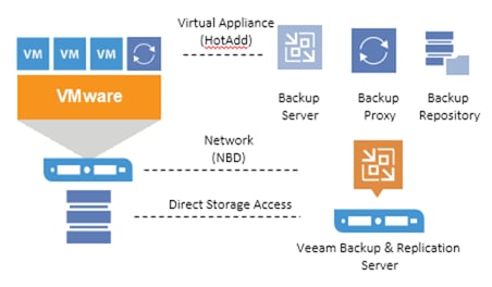
In the Direct storage access mode, Veeam Backup & Replication reads/writes data directly from/to the storage system where VM data or backups are located.
The Virtual appliance mode is recommended if the role of a Backup Proxy is assigned to a VM. In the Virtual appliance mode, Veeam Backup & Replication uses the VMware SCSI HotAdd capability that allows attaching devices to a VM while the VM is running. During backup, replication or restore disks of the processed VM are attached to the backup proxy. VM data is retrieved or written directly from/to the datastore, instead of going through the network.
The Network mode can be used with any infrastructure configuration. In this mode, data is retrieved via the ESX(i) host over the LAN using the Network Block Device protocol (NBD).
When estimating the amount of required disk space, you should know the following:
● Number of VMs to backup
● Total size of VMs and the data change rate
● Frequency of backups
● Retention period for backups
● Will jobs use forward or forever-forward incremental
● Frequency of active and synthetic fulls
It is important to understand the specific environment to find out possible exceptions:
● Data reduction thanks to compression and deduplication is usually 2:1 or more; it's common to see 3:1 or better, but you should always be conservative when estimating required space.
● Typical daily change rate is between 2 and 5% in a mid-size or enterprise environment; this can greatly vary among servers; some servers show much higher values. If possible, run monitoring tools like Veeam ONE to have a better understanding of the real change rate values.
● Include additional space for one-off full backups.
● Include additional space for backup chain transformation. For instance, with forward forever incremental, add at least the size of a full backup multiplied by 1.25x.
● Using the numbers above, you can estimate the required disk space for any job. Besides, always leave plenty of extra headroom for future growth, additional full backups, moving VMs, restoring VMs from tape.
![]() A repository sizing tool that can be used for estimation is available at http://rps.dewin.me/rpc/. Note that this tool is not officially supported by Veeam, and it should be used "as is", but it is nonetheless heavily used by Veeam Architects and regularly updated.
A repository sizing tool that can be used for estimation is available at http://rps.dewin.me/rpc/. Note that this tool is not officially supported by Veeam, and it should be used "as is", but it is nonetheless heavily used by Veeam Architects and regularly updated.
Deployment Hardware and Software
Table 2 and Table 3 lists the software revisions and physical components used throughout this document.
|
|
Components |
Software Version |
Comments |
| Compute & Storage |
Cisco UCS S3260 M5 Storage Server |
4.1(3b) |
Cisco UCS S3260 Storage Server is directly managed through Fabric Interconnect with local Veeam Repository |
|
|
Cisco UCS C240 All Flash Server |
4.1(3b) |
Cisco UCS C240 Rack Server with 24 x SSDs with local Veeam Repository |
|
|
Cisco UCS C220 Rack Server |
4.1(3b) |
Cisco UCS C220 Rack Server, SAN Boot from FlashArray//C |
|
|
Pure Storage FlashArray//C 60 |
Purity//FA 6.1.3 |
Pure Storage FlashArray//C as Veeam Repository |
|
|
Pure Storage FlashArray//X70R2 |
Purity//FA 6.1.3 |
Pure Storage FlashArray//X, storage for FlashStack |
| Management |
Cisco UCS Manager |
4.1(3b) |
Cisco UCS Management for all servers directly attached to Fabric Interconnects |
| Backup and Replication |
Veeam Availability Suite |
11.0.0.837 |
Configured with Veeam Backup Server, Veeam Backup Proxy, Veeam Backup Repository |
|
|
Operating System |
Windows 2019 Data Center Edition |
Version 1809, OS Build (17763.1098) |
| Virtualization |
VMware vSphere |
VMware ESXi, 7.0.1, 16850804 |
|
|
|
VMware vCenter |
vCenter 7.0.0 (Build 16323968) |
|
| Network |
Cisco Nexus 93180YC-FX |
NXOS: version 9.3(4) |
Cisco Platform Switch for ToR, |
|
|
Cisco MDS 9132T (32X32G ports) |
8.2(1) |
Cisco Platform Switch for Fibre Channel |
|
|
Cisco UCS 6454 FI |
4.1(3b) |
Fabric Interconnect with embedded Cisco UCS Manager for Cisco UCS S3260 Storage Server, Cisco UCS C240 All Flash Server, and Cisco UCS C220 Rack Server |
Table 3. Veeam Deployment Hardware Components
| Component |
Hardware Required |
| Fabric Interconnects |
2 Cisco UCS 6454 Fabric Interconnects |
| Servers |
1 Cisco UCS S3260 Storage Server with 56X8 TB (NL-SAS 7.2k) |
|
|
1 Cisco UCS C240 Rack Server with 24X1.9 TB SSD (Enterprise Value 6G SATA SSD) |
|
|
1 Cisco UCS C220 Rack Server with no disk (SAN Boot) |
| Storage |
1 FlashArray//C 60 for Veeam Backup Repository |
For complete server specifications and more information, please refer to the following links:
Cisco Fabric Interconnect 6454
Cisco UCS S3260 M5 Storage Server
The VLAN configuration recommended for the environment includes a total of six VLANs as outlined in Table 4.
Table 4. VLANs Configured in this Study
| VLAN Name |
VLAN ID |
VLAN Purpose |
| Default |
1 |
Native VLAN |
| In-Band-Mgmt |
215 |
In-Band management interfaces |
| Infra-Mgmt |
215 |
Infrastructure Virtual Machines |
| VCC/VM-Network |
215 |
Veeam Network interfaces |
| OOB-Mgmt |
15 |
Out of Band management interfaces |
Two virtual SANs were configured for communications and fault tolerance in this design to support backup traffic, as listed in Table 5.
Table 5. VSANs Configured in this Study
| VSAN Name |
VSAN ID |
Purpose |
| VSAN 102 |
102 |
VSAN for Primary SAN communication |
| VSAN 202 |
202 |
VSAN for Secondary SAN communication |
Cisco UCS systems and the Veeam software must be properly licensed for all software features in use, and for all ports in use on the Cisco UCS Fabric Interconnects. Please contact your resale partner or your direct Cisco and Veeam sales teams to ensure you order all the necessary and appropriate licenses for your solution.
![]() Veeam Universal Licenses include support for Veeam storage snapshot Integration.
Veeam Universal Licenses include support for Veeam storage snapshot Integration.
This section details the configuration and tuning that was performed on the individual components to produce a complete, validated solution.
The following sections detail the physical connectivity configuration of the solution deployed to protect the FlashStack environment.
The information provided in this section is a reference for cabling the physical equipment in this Cisco Validated Design environment. To simplify cabling requirements, the tables include both local and remote device and port locations.
This section describes the cabling required to protect a FlashStack environment. The key assumptions are as follows:
● Customers already have a pre-configured FlashStack environment
● Backup infrastructure has a separate pair of Cisco UCS Fabric Interconnect connected to Cisco MDS 9132T and Cisco Nexus TOR switches
● Cisco MDS 9132T and Cisco Nexus TOR switches are shared across the FlashStack environment and backup infrastructure.
● Customers have a choice to protect the FlashStack environment through Veeam Backup & Replication Server, with the following storage and compute targets:
◦ Cisco UCS S3260 storage server, providing both compute and storage for the Veeam Backup & Replication Server.
◦ Cisco UCS C240 All Flash Server with 24 SSDs, providing both compute and storage for the Veeam Backup & Replication Server.
◦ Cisco UCS C220 Rack Server connected to a FlashArray//C through Fibre Channel. Cisco UCS C220 Rack Server provides compute and FlashArray//C provides storage for the Veeam Backup & Replication Server.
The tables in this section list the details for the prescribed and supported configuration of the Pure Storage FlashArray//X70 R2 and Pure Storage FlashArray//C60 storage array to the Cisco 6454 Fabric Interconnects through Cisco MDS 9132T 32-Gb FC switches.
![]() This document assumes that out-of-band management ports are plugged into an existing management infrastructure at the deployment site. These interfaces will be used in various configuration steps.
This document assumes that out-of-band management ports are plugged into an existing management infrastructure at the deployment site. These interfaces will be used in various configuration steps.
![]() Be sure to follow the cabling directions in this section. Failure to do so will result in necessary changes to the deployment procedures that follow because specific port locations are mentioned.
Be sure to follow the cabling directions in this section. Failure to do so will result in necessary changes to the deployment procedures that follow because specific port locations are mentioned.
Figure 27 shows a cabling diagram for a configuration using the Cisco Nexus 9000, Cisco MDS 9100 Series, and Pure Storage FlashArray//X70 R2.
Figure 27. FlashStack Data Protection with Veeam Solution Cabling Diagram
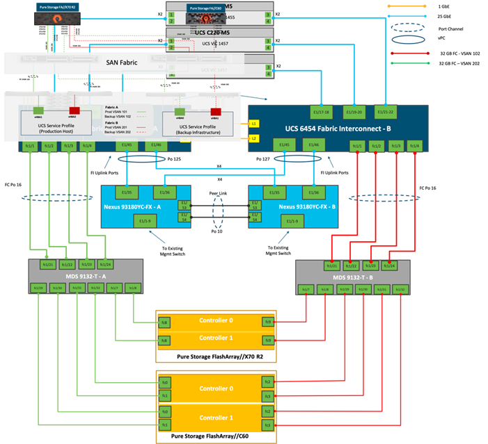
Cisco Unified Computing System Base Configuration
This section details the Cisco UCS configuration that was done as part of the infrastructure build out. The racking, power, and installation of the chassis are described in the Cisco UCS Manager Getting Started Guide and it is beyond the scope of this document. For more information about each step, refer to the following document, Cisco UCS Manager - Configuration Guides.
Cisco UCS Manager Software Version 4.1(3b)
This document assumes you are using Cisco UCS Manager Software version 4.1(3b). To upgrade the Cisco UCS Manager software and the Cisco UCS 6454 Fabric Interconnect software to a higher version of the firmware,) refer to Cisco UCS Manager Install and Upgrade Guides.
Configure Fabric Interconnects at Console
To configure the fabric Interconnects, follow these steps:
1. Connect a console cable to the console port on what will become the primary fabric interconnect.
2. If the fabric interconnect was previously deployed and you want to erase it to redeploy, follow these steps:
a. Login with the existing user name and password:
# connect local-mgmt
# erase config
# yes (to confirm)
3. After the fabric interconnect restarts, the out-of-box first time installation prompt appears, type “console” and press Enter.
4. Follow the Initial Configuration steps as outlined in Cisco UCS Manager Getting Started Guide. When configured, log into UCSM IP Address through Web interface to perform base Cisco UCS configuration.
Configure Fabric Interconnects for a Cluster Setup
To configure the Cisco UCS Fabric Interconnects, follow these steps:
1. Verify the following physical connections on the fabric interconnect:
a. The management Ethernet port (mgmt0) is connected to an external hub, switch, or router
b. The L1 ports on both fabric interconnects are directly connected to each other
c. The L2 ports on both fabric interconnects are directly connected to each other
2. Connect to the console port on the first Fabric Interconnect.
3. Review the settings on the console. Answer yes to Apply and Save the configuration.
4. Wait for the login prompt to make sure the configuration has been saved to Fabric Interconnect A.
5. Configure the first Fabric Interconnect, using the following example as a guideline:
---- Basic System Configuration Dialog ----
This setup utility will guide you through the basic configuration of
the system. Only minimal configuration including IP connectivity to
the Fabric interconnect and its clustering mode is performed through these steps.
Type Ctrl-C at any time to abort configuration and reboot system.
To back track or make modifications to already entered values,
complete input till end of section and answer no when prompted
to apply configuration.
Enter the configuration method. (console/gui) ? console
Enter the setup mode; setup newly or restore from backup. (setup/restore) ? setup
You have chosen to setup a new Fabric interconnect. Continue? (y/n): y
Enforce strong password? (y/n) [y]: y
Enter the password for "admin":
Confirm the password for "admin":
Is this Fabric interconnect part of a cluster(select 'no' for standalone)? (yes/no) [n]: yes
Enter the switch fabric (A/B) []: A
Enter the system name: AA12-DP-FI6454
Physical Switch Mgmt0 IP address : 192.168.164.62
Physical Switch Mgmt0 IPv4 netmask : 255.255.255.0
IPv4 address of the default gateway : 192.168.164.254
Cluster IPv4 address : 192.168.164.61
Configure the DNS Server IP address? (yes/no) [n]: yes
DNS IP address : 171.70.168.183
Configure the default domain name? (yes/no) [n]: yes
Default domain name : DP1.lab.cisco.com
Join centralized management environment (UCS Central)? (yes/no) [n]: no
Following configurations will be applied:
Switch Fabric=A
System Name=AA12-DP-FI6454
Enforced Strong Password=no
Physical Switch Mgmt0 IP Address=192.168.164.62
Physical Switch Mgmt0 IP Netmask=255.255.255.0
Default Gateway=192.168.164.254
Ipv6 value=0
DNS Server=171.70.168.183
Domain Name=DP1.lab.cisco.com
Cluster Enabled=yes
Cluster IP Address=192.168.164.61
NOTE: Cluster IP will be configured only after both Fabric Interconnects are initialized
Apply and save the configuration (select 'no' if you want to re-enter)? (yes/no): yes
Applying configuration. Please wait.
Configuration file – Ok
6. Connect the console port on the second Fabric Interconnect, configure secondary FI.
7. Configure the second Fabric Interconnect, using the following example as a guideline:
---- Basic System Configuration Dialog ----
This setup utility will guide you through the basic configuration of
the system. Only minimal configuration including IP connectivity to
the Fabric interconnect and its clustering mode is performed through these steps.
Type Ctrl-C at any time to abort configuration and reboot system.
To back track or make modifications to already entered values,
complete input till end of section and answer no when prompted
to apply configuration.
Enter the configuration method. (console/gui) ? console
Installer has detected the presence of a peer Fabric interconnect. This Fabric interconnect will be added to the cluster. Continue (y/n) ? y
Enter the admin password of the peer Fabric interconnect:
Connecting to peer Fabric interconnect... done
Retrieving config from peer Fabric interconnect... done
Peer Fabric interconnect Mgmt0 IPv4 Address: 192.168.164.62
Peer Fabric interconnect Mgmt0 IPv4 Netmask: 255.255.255.0
Cluster IPv4 address : 192.168.164.61
Peer FI is IPv4 Cluster enabled. Please Provide Local Fabric Interconnect Mgmt0 IPv4 Address
Physical Switch Mgmt0 IP address : 192.168.164.63
Apply and save the configuration (select 'no' if you want to re-enter)? (yes/no): yes
Applying configuration. Please wait.
Configuration file – Ok
To log into the Cisco Unified Computing System (Cisco UCS) environment, follow these steps:
1. Open a web browser and navigate to the Cisco UCS Fabric Interconnect cluster address previously configured.
2. Click the Launch UCS Manager link to download the Cisco UCS Manager software. If prompted, accept the security certificates.
Figure 28. Cisco UCS Manager Web Interface
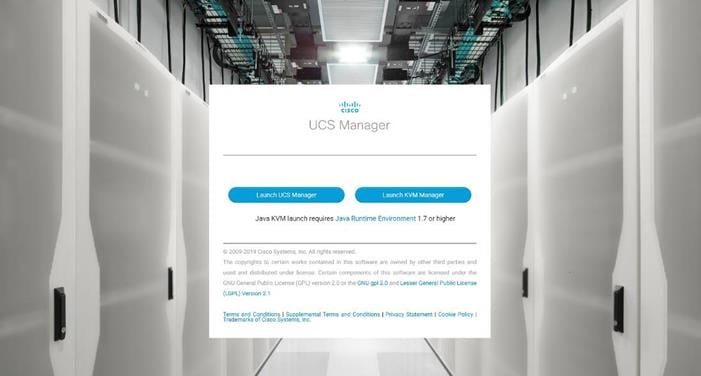
3. When prompted, enter the username and password enter the password. Click Log In to login to Cisco UCS Manager.
Figure 29. Cisco UCS Manager Web Interface after Login
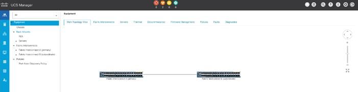
Configure Base Cisco Unified Computing System
The following are the high-level steps involved for a Cisco UCS configuration:
1. Configure Fabric Interconnects for a Cluster Setup.
2. Set Fabric Interconnects to Fibre Channel End Host Mode.
3. Synchronize Cisco UCS to NTP.
4. Configure Fabric Interconnects for Chassis and Blade Discovery:
a. Configure Global Policies
b. Configure Server Ports
5. Configure LAN and SAN on Cisco UCS Manager:
a. Configure Ethernet LAN Uplink Ports
b. Create Uplink Port Channels to Cisco Nexus Switches
c. Configure FC SAN Uplink Ports
d. Configure VLAN
e. Configure VSAN
6. Configure IP, UUID, Server, MAC, WWNN and WWPN Pools:
a. IP Pool Creation
b. UUID Suffix Pool Creation
c. Server Pool Creation
d. MAC Pool Creation
e. WWNN and WWPN Pool Creation
7. Set Jumbo Frames in both the Cisco Fabric Interconnect.
8. Configure Server BIOS Policy.
9. Create Adapter Policy.
10. Configure Update Default Maintenance Policy.
11. Configure vNIC and vHBA Template.
12. Create Server Boot Policy for SAN Boot.
Details for each step are discussed in the following sections.
To synchronize the Cisco UCS environment to the NTP server, follow these steps:
1. In Cisco UCS Manager, in the navigation pane, click the Admin tab.
2. Select All > Time Zone Management.
3. In the Properties pane, select the appropriate time zone in the Time Zone menu.
4. Click Save Changes and then click OK.
5. Click Add NTP Server.
6. Enter the NTP server IP address and click OK.
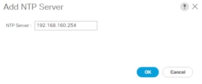
7. Click OK to finish.
8. Repeat steps 1-7 to configure additional NTP servers.
9. Click Save Changes.
Figure 30. Synchronize Cisco UCS Manager to NTP
Configure Fabric Interconnects for Chassis and Server Discovery
Cisco UCS 6454 Fabric Interconnects are configured for redundancy. It provides resiliency in case of failures. The first step is to establish connectivity between blades and Fabric Interconnects.
The chassis discovery policy determines how the system reacts when you add a new chassis. We recommend using the platform max value as shown. Using platform max helps ensure that Cisco UCS Manager uses the maximum number of IOM uplinks available.
To configure global policies, follow these steps:
1. In Cisco UCS Manager, go to Equipment > Policies > Global Policies > Chassis/FEX Discovery Policies. As shown in the screenshot below, for Action select “Platform Max” from the drop-down list and set Link Grouping to Port Channel.
2. Click Save Changes.
3. Click OK.
Figure 31. UCS Global Policy
Fabric Ports: Discrete versus Port Channel Mode
Figure 32 illustrates the advantage of Discrete versus Port-Channel mode in UCSM.
Figure 32. Port Channel versus Discrete Mode
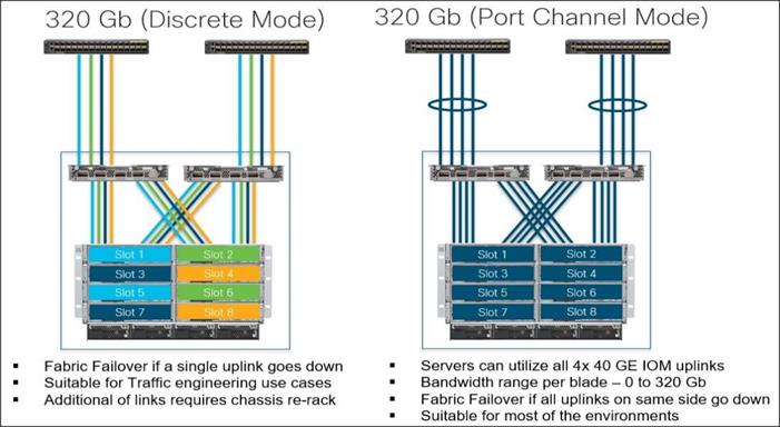
Set Fabric Interconnects to Fibre Channel End Host Mode
In order to configure the FC Uplink ports connected to the Cisco UCS MDS 9132T 32-Gb FC switch, set the Fabric Interconnects to the Fibre Channel End Host Mode. Verify that the fabric interconnects are operating in “FC End-Host Mode.”
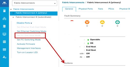
![]() The fabric interconnect automatically reboots if switched to operational mode; perform this task on one FI first, wait for the FI to come up and repeat this process on the second FI.
The fabric interconnect automatically reboots if switched to operational mode; perform this task on one FI first, wait for the FI to come up and repeat this process on the second FI.
Configure FC SAN Uplink Ports
To configure Fibre Channel Uplink ports, follow these steps:
1. Go to Equipment > Fabric Interconnects > Fabric Interconnect A > General tab > Actions pane, click Configure Unified Ports.
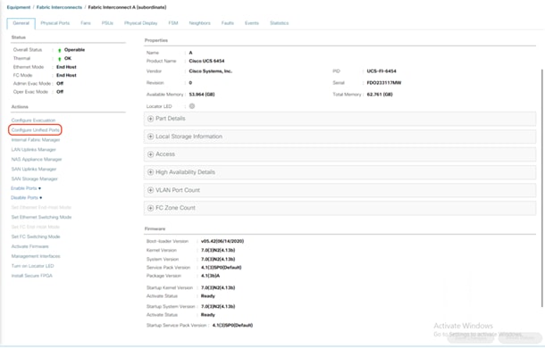
2. Click Yes to confirm in the pop-up window.
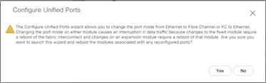
3. Move the slider to the right.
4. Click OK.
![]() Ports to the right of the slider will become FC ports. For our study, we configured the first four ports (Ports are configured in sets of 4 ports) on the FI as FC Uplink ports.
Ports to the right of the slider will become FC ports. For our study, we configured the first four ports (Ports are configured in sets of 4 ports) on the FI as FC Uplink ports.
![]() Applying this configuration will cause the immediate reboot of the fabric interconnect and/or the expansion module(s).
Applying this configuration will cause the immediate reboot of the fabric interconnect and/or the expansion module(s).
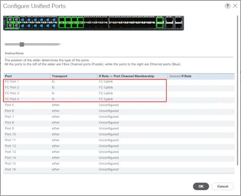
5. Click Yes to apply the changes.
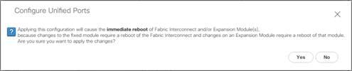
6. Click OK to proceed.
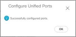
7. After the FI reboot, your FC Ports configuration will look like Figure 33.
8. Repeat steps 1-7 on Fabric Interconnect B.
Figure 33. FC Uplink Ports on Fabric Interconnect A
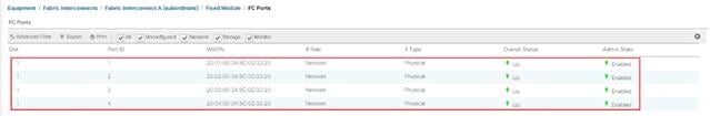
Configure Server Ports
Configure the server ports to initiate chassis and blade discovery. To configure server ports, follow these steps:
1. Go to Equipment > Fabric Interconnects > Fabric Interconnect A > Fixed Module > Ethernet Ports.
2. Select the ports (for this solution ports are 17-24) which are connected to the Cisco IO Modules of the two B-Series 5108 Chassis.
3. Right-click and select “Configure as Server Port.”
Figure 34. Configure Server Port on Cisco UCS Manager Fabric Interconnect for Chassis/Server Discovery
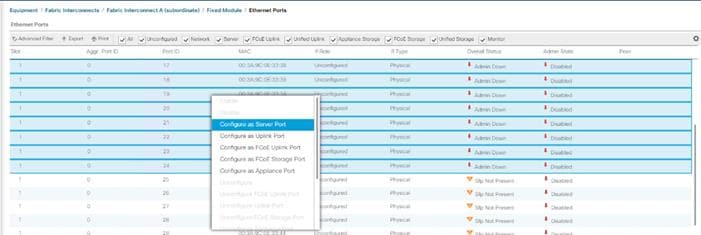
4. Click Yes to confirm and click OK.
5. Repeat steps 1-4 to configure the Server Port on Fabric Interconnect B.
When configured, the server port will look like Figure 35 on both Fabric Interconnects.
Figure 35. Server Ports on Fabric Interconnect A
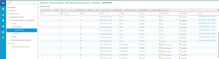
6. After configuring Server Ports, acknowledge both the Chassis. Go to Equipment >Chassis > Chassis 1 > General > Actions > select “Acknowledge Chassis”. Similarly, acknowledge the chassis 2-4.
7. After acknowledging both the chassis, re-acknowledge all the servers placed in the chassis. Go to Equipment > Chassis 1 > Servers > Server 1 > General > Actions > select Server Maintenance > select option “Re-acknowledge” and click OK. Repeat this process to re-acknowledge all eight Servers.
8. When the acknowledgement of the Servers is completed, verify the Port-channel of Internal LAN. Go to the LAN tab > Internal LAN > Internal Fabric A > Port Channels as shown in Figure 36.
Figure 36. Internal LAN Port Channels
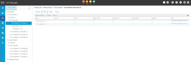
Configure Ethernet LAN Uplink Ports
To configure network ports that are used to uplink the Fabric Interconnects to the Cisco Nexus switches, follow these steps:
1. In Cisco UCS Manager, in the navigation pane, click the Equipment tab.
2. Select Equipment > Fabric Interconnects > Fabric Interconnect A > Fixed Module.
3. Expand Ethernet Ports.
4. Select ports (for this solution ports are 49-50) that are connected to the Nexus switches, right-click them, and select Configure as Network Port.
Figure 37. Network Uplink Port Configuration on Fabric Interconnect Configuration
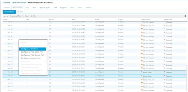
5. Click Yes to confirm ports and click OK.
6. Verify the Ports connected to Cisco Nexus upstream switches are now configured as network ports.
7. Repeat steps 1-6 for Fabric Interconnect B. The screenshot below shows the network uplink ports for Fabric A.
Figure 38. Network Uplink Port on Fabric Interconnect
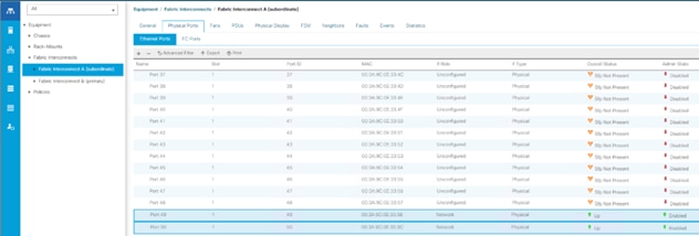
You have now created two uplink ports on each Fabric Interconnect as shown above. These ports will be used to create Virtual Port Channel in the next section.
Create Uplink Port Channels to Cisco Nexus Switches
In this procedure, two port channels were created, one from Fabric A to both Cisco Nexus 93180YC-FX switches and one from Fabric B to both Cisco Nexus 93180YC-FX switches. To configure the necessary port channels in the Cisco UCS environment, follow these steps:
1. In Cisco UCS Manager, click the LAN tab in the navigation pane.
2. Click LAN > LAN Cloud >Fabric A.
3. Right-click Port Channels.
4. Select Create Port Channel.
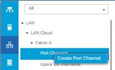
5. Enter 125 as the unique ID of the port channel and name of the port channel.
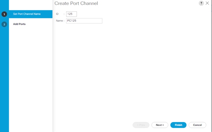
6. Click Next.
7. Select Ethernet ports 45-46 for the port channel.
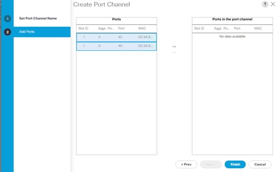
8. Click Finish.
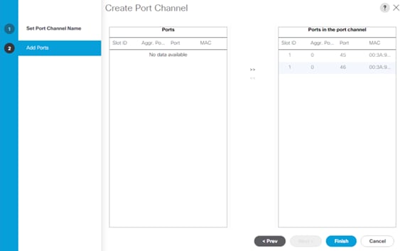
9. Click OK.
10. Repeat steps 1-9 for the Port Channel configuration on FI-B.
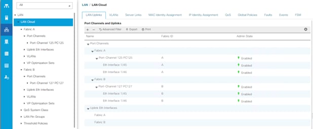
Configure VLAN
To configure the necessary virtual local area networks (VLANs) for the Cisco UCS environment, follow these steps:
1. In Cisco UCS Manager, click the LAN tab in the navigation pane.
2. Click LAN > LAN Cloud.
3. Right-click VLANs.
4. Select Create VLANs.
5. Enter Backup_Infra as the name of the VLAN to be used for Public Network Traffic.
6. Keep the Common/Global option selected for the scope of the VLAN.
7. Enter 215 as the ID of the VLAN ID.
8. Keep the Sharing Type as None.
9. Click OK.
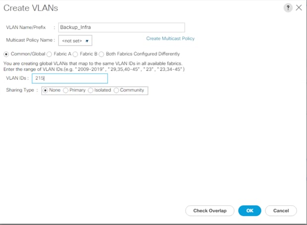
10. Repeat steps 1-9 to create required VLANs. Figure 39 shows the VLANs configured for this solution.
Figure 39. VLANs Configured for this Solution
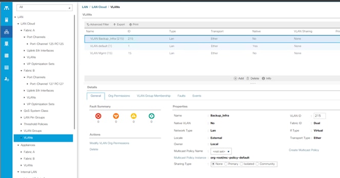
![]() IMPORTANT! Create both VLANs with global access across both fabric interconnects. This makes sure the VLAN identity is maintained across the fabric interconnects in case of a NIC failover.
IMPORTANT! Create both VLANs with global access across both fabric interconnects. This makes sure the VLAN identity is maintained across the fabric interconnects in case of a NIC failover.
Configure VSAN
To configure the necessary virtual storage area networks (VSANs) for the Cisco UCS environment, follow these steps:
1. In Cisco UCS Manager, click the SAN tab in the navigation pane.
2. Select SAN > SAN Cloud.
3. Under VSANs, right-click VSANs.
4. Select Create VSANs.
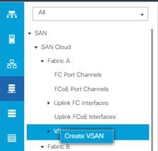
5. Enter the name of the VSAN, such as FS-Backup-A.
![]() In this solution, we created two VSANs; VSAN FS-Backup -A 102 on the Cisco UCS Fabric A and VSAN FS-Backup -B 202 on the Cisco UCS Fabric B for SAN Boot and Storage Access.
In this solution, we created two VSANs; VSAN FS-Backup -A 102 on the Cisco UCS Fabric A and VSAN FS-Backup -B 202 on the Cisco UCS Fabric B for SAN Boot and Storage Access.
6. Select Disabled for FC Zoning.
![]() In this solution, we used two Cisco MDS 9132T 32-Gb switches that provide Fibre Channel zoning.
In this solution, we used two Cisco MDS 9132T 32-Gb switches that provide Fibre Channel zoning.
7. Select Fabric A for the scope of the VSAN:
a. Enter 102 as VSAN ID and FCoE VLAN ID.
b. Click OK.
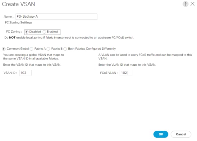
8. Repeat steps 1-7 to create the VSANs necessary for this solution.
Figure 40 shows VSAN 102 and 102 configured for this solution.
Figure 40. VSANs Configured for this Solution
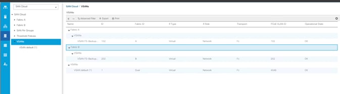
Create FC Port Channels to Cisco MDS Fibre Channel Switches
In this procedure, two port channels were created one from Fabric A to Cisco MDS 9132T-A switch and one from Fabric B to Cisco MDS 9132T-B Fibre Channel switches. To configure the necessary port channels in the Cisco UCS environment, follow these steps:
1. In Cisco UCS Manager, click the SAN tab in the navigation pane.
2. Click SAN > SAN Cloud >Fabric A.
3. Right-click FC Port Channels.
4. Select Create FC Port Channel.
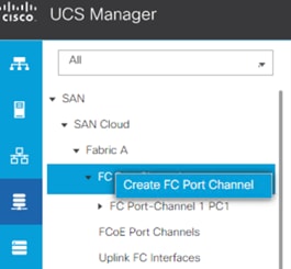
5. Use the default ID as 1 and name of the FC port channel.
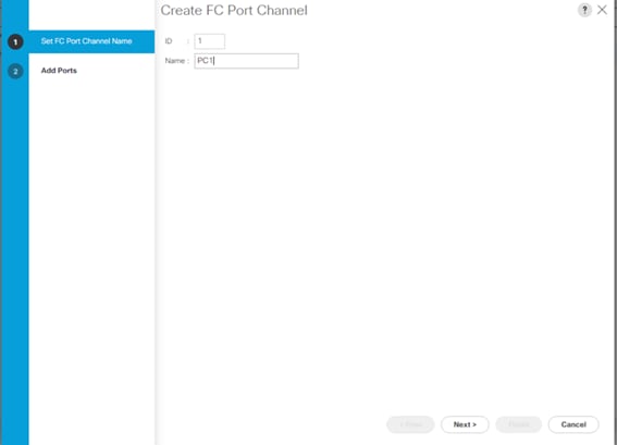
6. Click Next.
7. Select FC ports 1-4 for the port channel and Select Port Channel Admin Speed as 32Gbps.
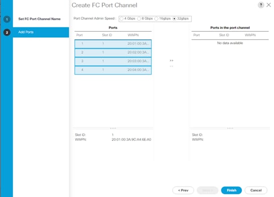
8. Add the ports in the Port Channel by select ‘>>’ marker and click Finish. The screenshot below illustrates FC port channel with FC ports 1-4 on Fabric A.
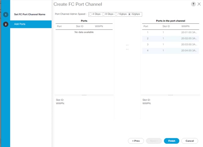
9. Select VSAN 102 and click Save Changes.
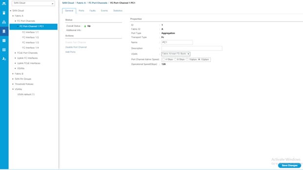
10. Repeat steps 1-9 for the FC Port Channel configuration on FI-B. Screenshot below illustrates FC port channel on Fabric A and Fabric B.
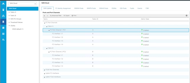
Create New Sub-Organization
To configure the necessary Sub-Organization for the Cisco UCS environment, follow these steps:
1. In Cisco UCS Manager, click the Servers tab in the navigation pane.
2. Select root > Sub-Organization.
3. Right-click Sub-Organization.
4. Enter the name of the Sub-Organization.
5. Click OK.
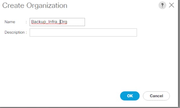
![]() You will create pools and policies required for this solution under the newly created “Backup_infra_Org” sub-organization.
You will create pools and policies required for this solution under the newly created “Backup_infra_Org” sub-organization.
Configure IP, UUID, Server, MAC, WWNN, and WWPN Pools
IP Pool Creation
An IP address pool on the out of band management network must be created to facilitate KVM access to each compute node in the Cisco UCS domain. To create a block of IP addresses for server KVM access in the Cisco UCS environment, follow these steps:
1. In Cisco UCS Manager, in the navigation pane, click the LAN tab.
2. Click Pools > root > Sub-Organizations > Backup_Infra_Org > IP Pools > click Create IP Pool.
3. Select the option Sequential to assign IP in sequential order then click Next.
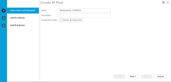
4. Click Add IPv4 Block.
5. Enter the starting IP address of the block and the number of IP addresses required, and the subnet and gateway information as shown below.
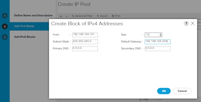
UUID Suffix Pool Creation
To configure the necessary universally unique identifier (UUID) suffix pool for the Cisco UCS environment, follow these steps:
1. In Cisco UCS Manager, click the Servers tab in the navigation pane.
2. Click Pools > root > Sub-Organization > Backup_Infra_Org.
3. Right-click UUID Suffix Pools and then select Create UUID Suffix Pool.
4. Enter the name of the UUID name.
5. Optional: Enter a description for the UUID pool.
6. Keep the prefix at the derived option and select Sequential in as Assignment Order then click Next.
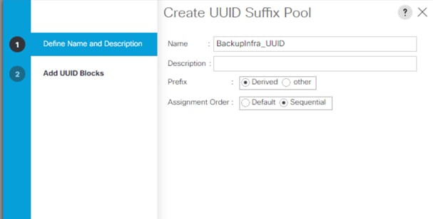
7. Click Add to add a block of UUIDs.
8. Create a starting point UUID as per your environment.
9. Specify a size for the UUID block that is sufficient to support the available blade or server resources.
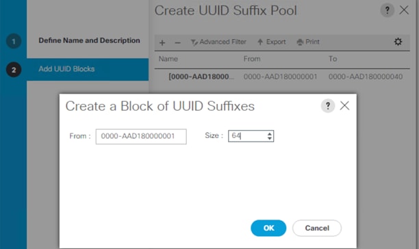
MAC Pool Creation
To configure the necessary MAC address pools for the Cisco UCS environment, follow these steps:
1. In Cisco UCS Manager, click the LAN tab in the navigation pane.
2. Click Pools > root > Sub-Organization > Backup_Infra_Org > right-click MAC Pools under the root organization.
3. Click Create MAC Pool to create the MAC address pool.
4. Enter name for MAC pool. Select Assignment Order as “Sequential.”
5. Enter the seed MAC address and provide the number of MAC addresses to be provisioned.
6. Click OK and then click Finish.
7. In the confirmation message, click OK.
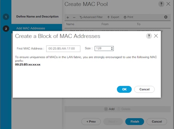
8. Create MAC Pool B and assign unique MAC Addresses as shown below.
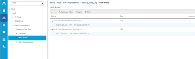
WWNN and WWPN Pool Creation
To configure the necessary WWNN pools for the Cisco UCS environment, follow these steps:
1. In Cisco UCS Manager, click the SAN tab in the navigation pane.
2. Click Pools > Root > Sub-Organization > Backup_Infra_Org > WWNN Pools > right-click WWNN Pools > select Create WWNN Pool.
3. Assign a name and select the Assignment Order as sequential:
a. Click Next and then click Add to add block of Ports.
b. Enter Block for WWN and size of WWNN Pool as shown below.
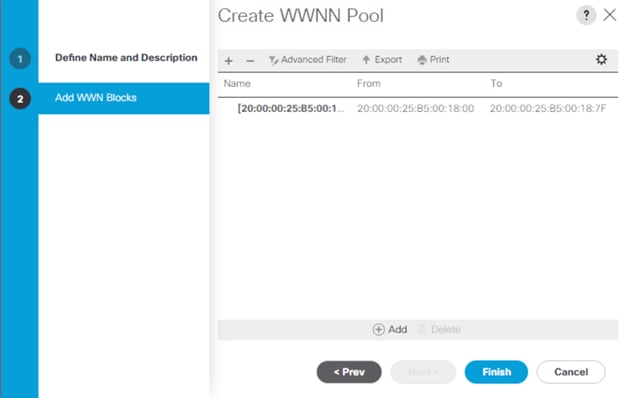
c. Click OK and then click Finish.
To configure the necessary WWPN pools for the Cisco UCS environment, follow these steps:
![]() We created two WWPN as WWPN-A Pool and WWPN-B as World Wide Port Name as shown below. These WWNN and WWPN entries will be used to access storage through SAN configuration.
We created two WWPN as WWPN-A Pool and WWPN-B as World Wide Port Name as shown below. These WWNN and WWPN entries will be used to access storage through SAN configuration.
1. In Cisco UCS Manager, click the SAN tab in the navigation pane.
2. Select Pools > Root > Sub-Organization > Backup_Infra_Org >WWPN Pools > right-click WWPN Pools > select Create WWPN Pool.
3. Assign name and Assignment Order as sequential.
4. Click Next and then click Add to add block of Ports.
5. Enter Block for WWN and size.
6. Click OK and then click Finish.
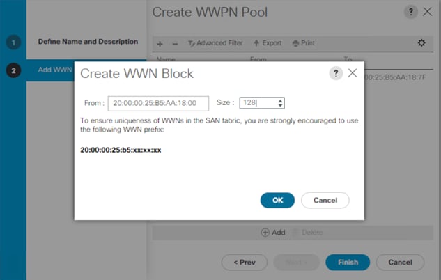
7. Configure the WWPN-B Pool and assign the unique block IDs as shown below.
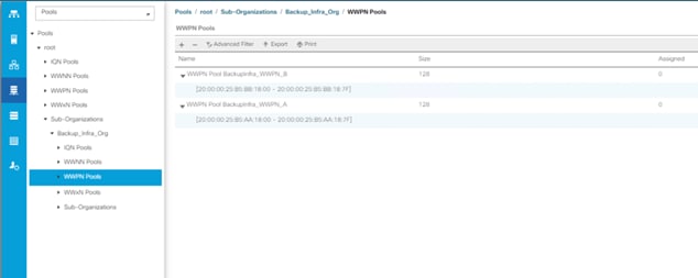
Set Jumbo Frames in both the Cisco Fabric Interconnect
To configure jumbo frames and enable quality of service in the Cisco UCS fabric, follow these steps:
1. In Cisco UCS Manager, click the LAN tab in the navigation pane.
2. Select LAN > LAN Cloud > QoS System Class.
3. In the right pane, click the General tab.
4. On the Best Effort row, enter 9216 in the box under the MTU column.
5. Click Save Changes.
6. Click OK.
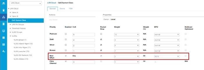
Firmware management policies allow the administrator to select the corresponding packages for a given server configuration. These policies often include packages for adapter, BIOS, board controller, FC adapters, host bus adapter (HBA) option ROM, and storage controller properties.
To create a firmware management policy for a given server configuration in the Cisco UCS environment, follow these steps:
1. In Cisco UCS Manager, click the Servers tab in the navigation pane.
2. Select root > Sub-Organization > Backup_Infra_Org > Host Firmware Packages.
3. Right-click Host Firmware Packages.
4. Select Create Host Firmware Package.
5. Enter name of the host firmware package.
6. Leave Simple selected.
7. Select the version 4.1(3b) for both the Blade Package.
8. Deselect Local Disk
9. Click OK to create the host firmware package.
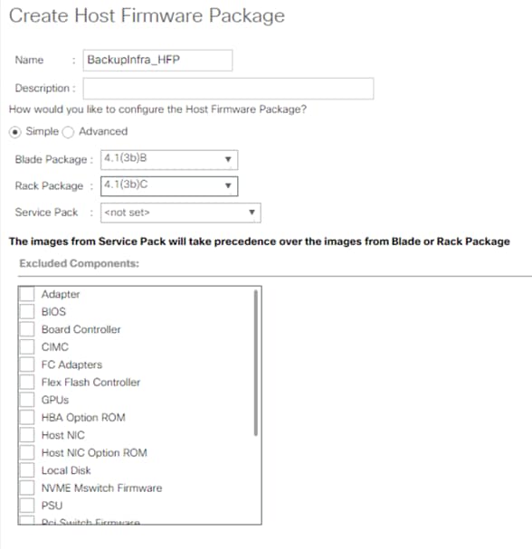
Create Network Control Policy for Cisco Discovery Protocol
To create a network control policy that enables Cisco Discovery Protocol (CDP) on virtual network ports, follow these steps:
1. In Cisco UCS Manager, click the LAN tab in the navigation pane.
2. Click Policies > root > Sub-Organization > Backup_Infra_Org > Network Control Policies.
3. Right-click Network Control Policies.
4. Click Create Network Control Policy.
5. Enter policy name.
6. Select the Enabled option for “CDP.”
7. Click OK to create the network control policy.
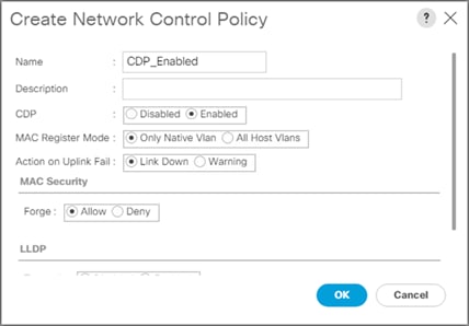
To create a power control policy for the Cisco UCS environment, follow these steps:
1. In Cisco UCS Manager, click the Servers tab in the navigation pane.
2. Click Policies > root > Sub-Organization > Backup_Infra_Org > Power Control Policies.
3. Right-click Power Control Policies.
4. Click Create Power Control Policy.
5. Select Fan Speed Policy as “Max Power.”
6. Enter NoPowerCap as the power control policy name.
7. Change the power capping setting to No Cap.
8. Click OK to create the power control policy.
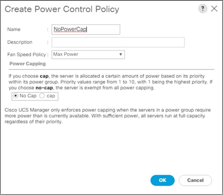
To create a server BIOS policy for the Cisco UCS environment, follow these steps:
1. In Cisco UCS Manager, click the Servers tab in the navigation pane.
2. Click Policies > root > Sub-Organization > Backup_Infra_Org > BIOS Policies.
3. Right-click BIOS Policies.
4. Click Create BIOS Policy.
5. Enter BackupInfra_BIOS as the BIOS policy name.
6. Keep options under Main” tab as Platform dependent.
7. Click Finish to create the BIOS policy.
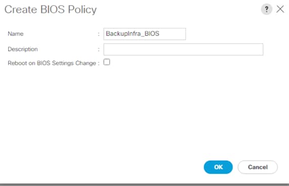
8. Go to Advanced options > Processor.
Table 6 lists the details of the Processor Options.
Table 6. Processor BIOS Options
| Processor options |
Value |
| Energy Efficient Turbo |
Disabled |
| Package C State Limit |
Co C1State |
| Autonomous Core C State |
Disabled |
| Processor C State |
Disabled |
| Processor C1E |
Disabled |
| Processor C3 Report |
Disabled |
| Processor C6 Report |
Disabled |
| Processor C7 Report |
Disabled |
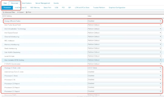
9. Go to Advanced tab > RAS Memory.
10. Select Maximum Performance Value for Memory RAS Configuration row.
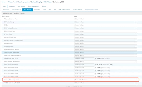
11. Click Save Changes.
12. Click OK.
![]() The recommended BIOS settings are critical for maximum Veeam Backup Performance on the Cisco UCS Servers.
The recommended BIOS settings are critical for maximum Veeam Backup Performance on the Cisco UCS Servers.
To update the default Maintenance Policy, follow these steps:
1. In Cisco UCS Manager, click the Servers tab in the navigation pane.
2. Click Policies > root > Sub-Organization > FlashStack-CVD > Maintenance Policies.
3. Right-click Maintenance Policies to create a new policy.
4. Enter name for Maintenance Policy
5. Change the Reboot Policy to User Ack.
6. Click Save Changes.
7. Click OK to accept the change.
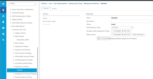
To create multiple virtual network interface card (vNIC) templates for the Cisco UCS environment, follow these steps:
1. In Cisco UCS Manager, click the LAN tab in the navigation pane.
2. Click Policies > root > Sub-Organization > Backup_Infra_Org > vNIC Template.
3. Right-click vNIC Templates.
4. Click Create vNIC Template.
5. Enter name for vNIC template.
6. Keep Fabric A selected. Select Enable Failover checkbox.
7. For Redundancy Type, Select “No Redundancy.”
8. Select Updating Template as the Template Type.
9. Under VLANs, select the checkboxes for desired VLANs to add as part of the vNIC Template.
10. Set Native-VLAN as the native VLAN.
11. For MTU, enter 9000.
12. In the MAC Pool list, select MAC Pool configure for Fabric A.
13. In the Network Control Policy list, select CDP_Enabled.
14. Click OK to create the vNIC template.
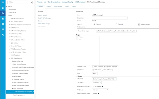
Create Ethernet Adapter Policy
To create ethernet adapter policy, follow these steps:
1. In Cisco UCS Manager, click the Servers tab in the navigation pane.
2. Select Policies > root > Sub-Organizations > Backup_Infra_Org.
3. Right-click Adapter Policies and select Ethernet Adapter Policy.
4. For the name enter veeam_adaptorpol.
5. Enter Transmit Queues = Receive Queues = 8, Ring Size = 4096.
6. Enter Completion Queues = 16 and Interrupts = 32.
7. Under Options, ensure Receive Side Scaling (RSS) is enabled.
8. Click OK.
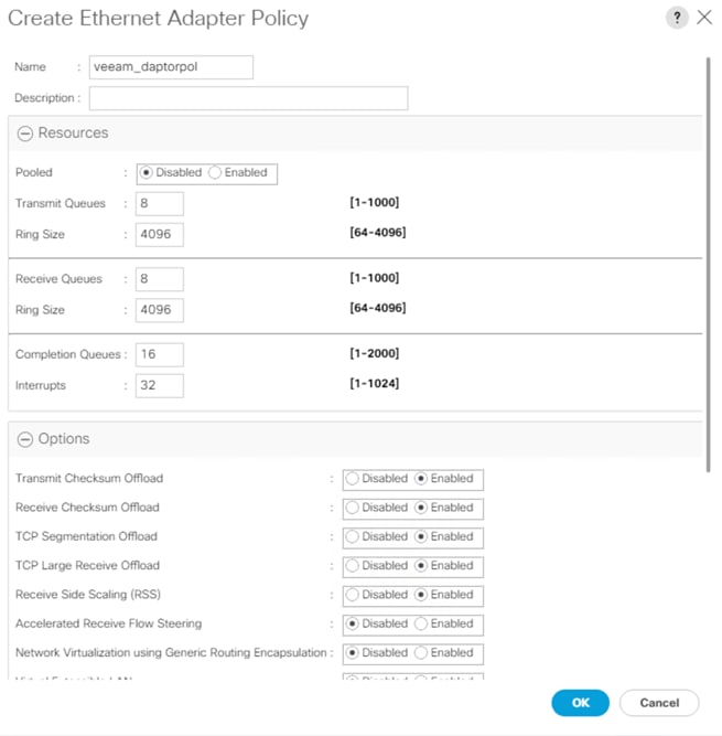
![]() To enable maximum throughout, it is recommended to change the default size of Rx and Tx Queues. RSS should be enabled, since it allows the distribution of network receive processing across multiple CPUs in a multiprocessor.
To enable maximum throughout, it is recommended to change the default size of Rx and Tx Queues. RSS should be enabled, since it allows the distribution of network receive processing across multiple CPUs in a multiprocessor.
To create FC adapter policy, follow these steps:
1. In Cisco UCS Manager, click the Servers tab in the navigation pane.
2. Select Policies > root > Sub-Organizations > Backup_Infra_Org.
3. Right-click Adapter Policies and select Fibre Channel Adapter Policy.
4. For the name enter veeam_fc_adp_pol.
5. Keep the Resources to default.
6. Under Options, Edit the Port Down time Timeout and Link Down Timeout to 10000 msec.
7. Click OK.
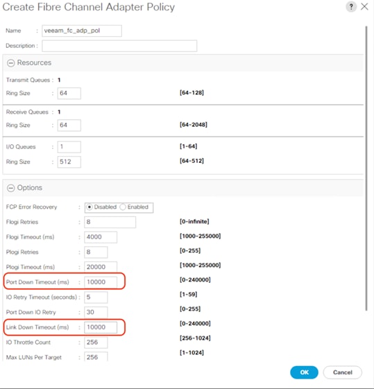
![]() To ensure no loss of IO during either FlashArray Controller or Cisco MDS failure, customers should apply the recommended Fibre Channel Adapter policy to vHBA.
To ensure no loss of IO during either FlashArray Controller or Cisco MDS failure, customers should apply the recommended Fibre Channel Adapter policy to vHBA.
To create multiple virtual host bus adapter (vHBA) templates for the Cisco UCS environment, follow these steps:
1. In Cisco UCS Manager, click the SAN tab in the navigation pane.
2. Click Policies > root > Sub-Organization > Backup_Infra_Org- > vHBA Template.
3. Right-click vHBA Templates.
4. Click Create vHBA Template.
5. Enter vHBA-A as the vHBA template name.
6. Keep Fabric A selected.
7. Select VSAN created for Fabric A from the drop-down list.
8. Change to Updating Template.
9. For Max Data Field keep 2048.
10. Select WWPN Pool for Fabric A (created earlier) for our WWPN Pool.
11. Leave the remaining fields as-is.
12. Click OK.
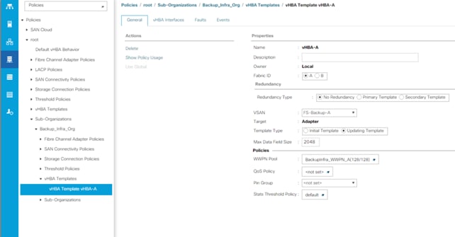
13. Repeat steps 1-12 to create a vHBA Template for Fabric B.
Create Server Boot Policy for SAN Boot
![]() Create Server Boot Policy for SAN Boot, applies only for customers deploying Veeam Backup & Replication Server on Cisco UCS C220 rack server with SAN Boot and Veeam Backup Repository on Pure Storage FlashArray//C.
Create Server Boot Policy for SAN Boot, applies only for customers deploying Veeam Backup & Replication Server on Cisco UCS C220 rack server with SAN Boot and Veeam Backup Repository on Pure Storage FlashArray//C.
In this configuration guide, there are three different Backup Storage Targets for Veeam. SAN Boot Policy applies only when customers are using FlashArray//C as the Veeam Backup Repository. SAN Boot Policy does not apply when customers choose to use either Cisco UCS S3260 storage Server or Cisco UCS C240 All Flash Rack Server as Veeam Storage Repository.
The Cisco UCS C220 M5 server deployed with Veeam Backup Proxy and Veeam Management Console for backup to FlashArray//C is set to boot from SAN for this Cisco Validated Design as part of the Service Profile template. The benefits of booting from SAN are numerous; disaster recovery, lower cooling, and power requirements for each server since a local drive is not required, and better performance, to name just a few.
![]() It is strongly recommended that you use “Boot from SAN” to realize the full benefits of Cisco UCS stateless computing features, such as service profile mobility.
It is strongly recommended that you use “Boot from SAN” to realize the full benefits of Cisco UCS stateless computing features, such as service profile mobility.
![]() This process applies to a Cisco UCS environment in which the storage SAN ports are configured as explained in the following section.
This process applies to a Cisco UCS environment in which the storage SAN ports are configured as explained in the following section.
![]() A Local disk configuration for the Cisco UCS is necessary if the servers in the environments have a local disk.
A Local disk configuration for the Cisco UCS is necessary if the servers in the environments have a local disk.
![]() SAN Boot Policy applies only when customers are using FlashArray//C as the Veeam Backup Repository
SAN Boot Policy applies only when customers are using FlashArray//C as the Veeam Backup Repository
To configure Local disk policy, follow these steps:
1. Go to tab Servers > Policies > root > Sub-Organization > Backup_Infra_Org- > right-click Local Disk Configuration Policy > Enter “SAN-Boot” as the local disk configuration policy name and change the mode to “No Local Storage.”
2. Click OK to create the policy.
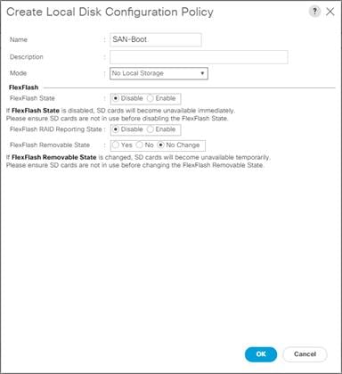
As shown in the screenshot below, the Pure Storage FlashArray//C has eight active FC connections that pair with the Cisco MDS 9132T 32-Gb switches.
Four FC ports are connected to Cisco MDS-A and the other Four FC ports are connected to Cisco MDS-B Switches. All FC ports are 32 Gb/s. The SAN Port CT0.FC0 and CT0.FC1 of Pure Storage FlashArray//C Controller 0 is connected to Cisco MDS Switch A. SAN port CT0.FC2 and CT0.FC3 is connected to MDS Switch B.
The SAN Port CT1.FC0 and CT1.FC1 of Pure Storage FlashArray//C Controller 1 is connected to Cisco MDS Switch A. SAN port CT1.FC2 and CT1.FC3 is connected to MDS Switch B.
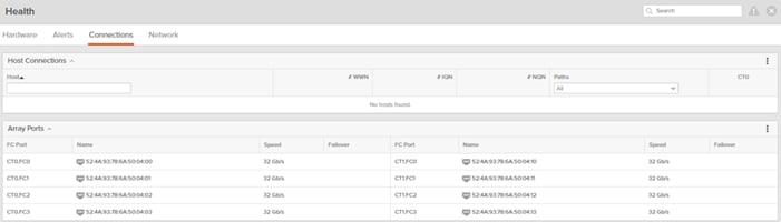
Create SAN Policy A
The SAN-A boot policy configures the SAN Primary's primary-target to be port CT0.FC0 on the Pure Storage FlashArray//C cluster and SAN Primary's secondary-target to be port CT1.FC0 on the Pure Storage cluster. Similarly, the SAN Secondary’s primary-target should be port CT1.FC2 on the Pure Storage cluster and SAN Secondary's secondary-target should be port CT0.FC2 on the Pure Storage cluster.
To create SAN policy A, follow these steps:
1. Log into the storage controller and verify all the port information is correct. This information can be found in the Pure Storage GUI under System > Connections > Target Ports.
2. You have to create a SAN Primary (hba0) and a SAN Secondary (hba1) in SAN-A Boot Policy by entering WWPN of Pure Storage FC Ports as explained in the following section.
To create Boot Policies for the Cisco UCS environments, follow these steps:
1. Go to Cisco UCS Manager and then go to Servers > Policies > root > Sub Organization > Backup_Infra-Org > Boot Policies. Right-click and select Create Boot Policy.
2. Enter SAN-A as the name of the boot policy.
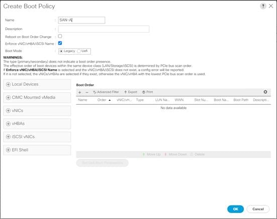
3. Expand the Local Devices drop-down list and Choose Add CD/DVD.
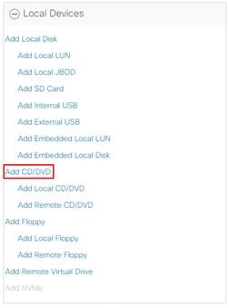
4. Expand the vHBAs drop-down list and Choose Add SAN Boot.
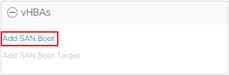
![]() The SAN boot paths and targets will include primary and secondary options in order to maximize resiliency and number of paths.
The SAN boot paths and targets will include primary and secondary options in order to maximize resiliency and number of paths.
5. In the Add SAN Boot dialog box, for Type select “Primary” and name vHBA as “vHBA0.” Click OK to add SAN Boot.
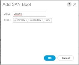
6. Select add SAN Boot Target.
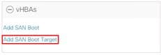
7. Keep 1 as the value for Boot Target LUN. Enter the WWPN for FC port CT0.FC0 of Pure Storage FlashArray//C and add SAN Boot Primary Target.
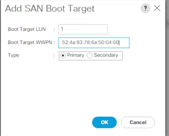
8. Add a secondary SAN Boot target into same hba0, enter the boot target LUN as 1 and WWPN for FC port CT1.FC0 of Pure Storage FlashArray//C, and add SAN Boot Secondary Target.
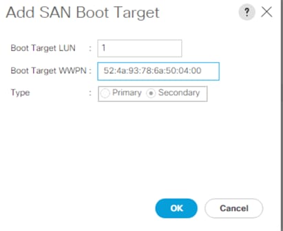
9. From the vHBA drop-down list and choose Add SAN Boot. In the Add SAN Boot dialog box, enter "vHBA1" in the vHBA field. Click OK to SAN Boot, then choose Add SAN Boot Target.
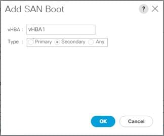
10. Keep 1 as the value for the Boot Target LUN. Enter the WWPN for FC port CT1.FC2 of Pure Storage FlashArray//C and add SAN Boot Primary Target.

11. Add a secondary SAN Boot target into same vhba1 and enter the boot target LUN as 1 and WWPN for FC port CT0.FC2 of Pure Storage FlashArray//C and add SAN Boot Secondary Target.
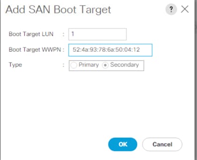
12. Click Save Changes.
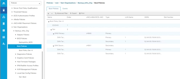
13. After creating the FC boot policy, you can view the boot order in the Cisco UCS Manager GUI. To view the boot order, navigate to Servers > Policies > Boot Policies. Click Boot Policy SAN-Boot-A to view the boot order in the right pane of the Cisco UCS Manager as shown below:
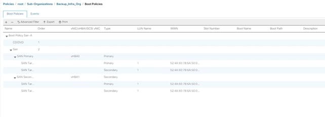
![]() For this solution, we created a single Boot Policy as “SAN-A”. For Service Profile of C220 Rack Server with Veeam Backup and Replication Server with Pure StorageFlashArray//C as the storage target, we will assign SAN-A as the SAN Boot Policy.
For this solution, we created a single Boot Policy as “SAN-A”. For Service Profile of C220 Rack Server with Veeam Backup and Replication Server with Pure StorageFlashArray//C as the storage target, we will assign SAN-A as the SAN Boot Policy.
![]() Cisco UCS S3260 storage server and Cisco UCS C240 M5 All Flash Rack Server are provisioned with local disk. Veeam Backup & Replication Server will boot from local disk installed on the Rear drive slots on each of the two servers.
Cisco UCS S3260 storage server and Cisco UCS C240 M5 All Flash Rack Server are provisioned with local disk. Veeam Backup & Replication Server will boot from local disk installed on the Rear drive slots on each of the two servers.
Configure and Create a Chassis Profile Template
Create Chassis Firmware Packages
To create S3260 Chassis Firmware packages, follow these steps:
1. In the Navigation pane, click the Chassis tab.
2. In the Chassis tab, expand Policies > root > sub-Organizations > Backup_Infra_Org.
3. Right-click Chassis Firmware Packages and select Create Chassis Firmware Packages.
4. Enter Chassis_FW as the Package name.
5. Select 4.1(3b)C from the Chassis Package drop-down list.
6. Uncheck Local Disk.
7. Click OK.
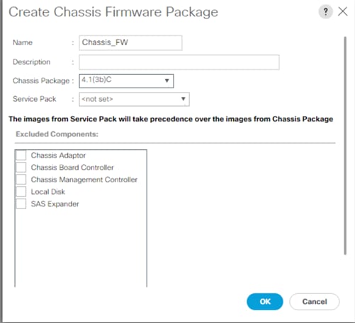
You can assign disk drives to the server nodes using disk zoning. Disk zoning can be performed on the controllers in the same server or on the controllers on different servers.
The S3260 Storage server node is equipped with 56 top load drives and a dual-chip controller with 4G flash-backed write cache for each controller. To utilize the 4G cache on both chips, customers need to assign 28 disks to each chip of the controller. This will require creating a Veeam Scale Out Backup Repository across two RAID60 disk group volumes.
Some of the benefits of having two disk RAID 60 volumes of 28 disk each are as follows:
● Utilize 4G cache on each chip of the dual-chip RAID controller, leading to much higher Veeam Backup throughput on a Scale Out Backup Repository. The performance section elaborates on the performance benefits of this configuration compared to a single RIAD60 volume across 56 drives on Cisco UCS S3260 storage server
● In the event of disk failures on any of the disk volumes, customers can expect better disk failure recovery times with the benefit of narrowing the disk failure to either one of the disk volumes.
Customers looking to avoid Veeam Scale out Repository can assign all 56 disks to a single chip of dual-chip RAID controller and create a RAID60 Volume across 56 drives on Cisco UCS S3260 storage server. Please refer to the “Disk Zoning” section of the Cisco HyperFlex Core and Edge Multisite Protection with Veeam deployment guide.
To create S3260 Disk Zoning Policy, follow these steps:
1. In the Navigation pane, click Chassis.
2. Expand Policies > root > Sub-Organizations > Backup_Infra_Org.
3. Right-click Disk Zoning Policies and choose Create Disk Zoning Policy.
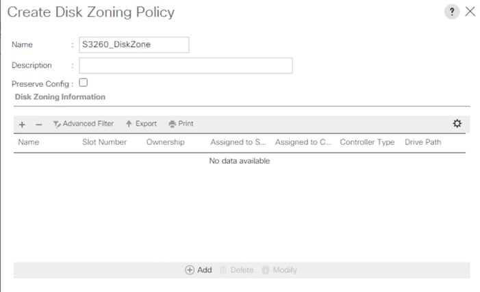
4. Enter S3260_DiskZone as the Disk Zone Name.
5. In the Disk Zoning Information Area, click Add.
6. Select Ownership as Dedicated.
7. Select Server as 1 (disk is assigned to node 1 of the S3260 Storage server).
8. Select Controller as 1.
9. Slot range as 1-28 (in the present setup there are 56 X8 TB SAS drives).
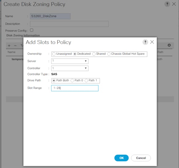
10. Click OK
11. Repeat steps 5-9 and select Server as 1 and Controller as 2 and Slot Range as 29-56, as shown below:
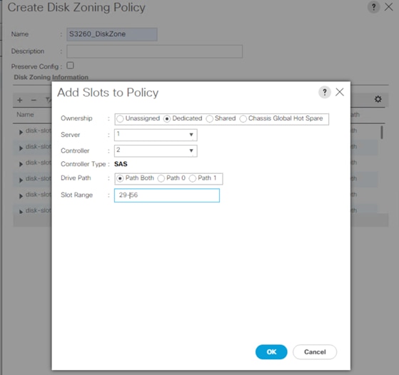
12. Click OK and again OK.
The actual disk zoning configuration with different chips on dual RAID controller is detailed below:
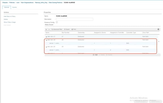
![]() Customers selecting a single large repository for Veeam on S3260 storage server, should assign all disk (1-56) to Server 1 and Controller 1.
Customers selecting a single large repository for Veeam on S3260 storage server, should assign all disk (1-56) to Server 1 and Controller 1.
Set Cisco UCS S3260 Disk to Unconfigured Good
To prepare all disks from the Cisco UCS S3260 Storage Servers for storage profiles, the disks have to be converted from JBOD to Unconfigured Good. To convert the disks, follow these steps:
1. Select the Equipment tab in the left pane of the Cisco UCS Manager GUI.
2. Go to Equipment >Chassis > Chassis 1 > Storage Enclosures > Enclosure1.
3. Select disks and right-click Set JBOD to Unconfigured Good.
Create Disk Group Policy for Cisco UCS S3260 Storage Server
A storage profile encapsulates the storage requirements for one or more service profiles. LUNs configured in a storage profile can be used as boot LUNs or data LUNs and can be dedicated to a specific server. You can also specify a local LUN as a boot device. The introduction of storage profiles allows you to do the following:
● Configure multiple virtual drives and select the physical drives that are used by a virtual drive. You can also configure the storage capacity of a virtual drive.
● Configure the number, type, and role of disks in a disk group.
● Associate a storage profile with a service profile
The Cisco UCS Manager Storage Profile and Disk Group Policies are utilized to define storage disks, disk allocation, and management in the Cisco UCS S3260 system. You would create two disk Group Policies as follows:
● RAID 1 from two Rear SSDs for OS Boot
● Two RAID60 across 1-28 disk and 29-56 disk as defined under Disk Zoning Policy. Table 7 lists the RAID Policies which can be configured on Cisco UCS S3260.
● Customers looking to avoid Veeam Scale-Out Repository can assign all 56 disks to a single chip of dual-chip RAID controller and create a RAID60 Volume across 56 drives on S3260 storage server. Please refer to the “Create Disk Group Policy” section of the Cisco HyperFlex Core and Edge Multisite Protection with Veeam deployment guide.
● RAID Configurations are elaborated in Table 7, and the table Row marked in BOLD is followed in the present deployment
Table 7. RAID Group Configuration on Cisco UCS S3260
| # Disk |
RAID Group |
# SPANs |
# Disk per SPAN |
# Global Hot Spares |
Veeam Repository Type |
| 14 |
RAID 6 |
NA |
NA |
1 |
Single Repository |
| 28 |
RAID 60 |
2 |
13 |
2 |
Single Repository |
| 42 |
1 x RAID 60 |
3 |
13 |
3 |
Single Repository |
| 56 |
2 x RAID 60 |
2 |
13 |
4 |
Veeam Scale-Out Repository |
| 56 |
1 x RAID60 |
4 |
13 |
4 |
Single Repository |
To create the Disk Group Policy, follow these steps:
1. In Cisco UCS Manager, click the Storage tab in the navigation pane.
2. Select Storage Policies > root >Sub-Organizations > Backup_Infra_Org >Disk Group Policies.
3. Right Click on Disk Group Policy and Select Create Disk Group Policy.
4. For the name enter S3260_RAID1_OS.
a. Select RAID Level as RAID1 Mirrored.
b. Number of drives as 2 and Drive Type as SSD.
c. Strip Size = 64KB, Access Policy = Read Write, Write Cache Policy = Write Back Good BBU, IO Policy = Direct, Drive Cache = Direct.
d. Click OK.
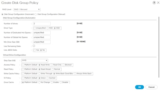
e. Create a second Disk Group Policy with RAID 60, with drives on slot 1-28. Name the Disk Group Policy as ‘S3260_RD60_1-28
f. For 28 DISK configurations of RAID60, we would have 2 SPANs and each SPAN would have 13 disks.
g. Remaining 2 DISK are allocated for Global Hot Spares.
h. For the name enter S3260RD60-1-28, Select RAID60 from RAID Level and opt for Manual Disk Group Configuration.
i. Click Add, Enter Slot Number as 1, Role as Normal and Span ID as 0.

j. Repeat step d, for Slot numbers 2 to 13 with Span ID 0.
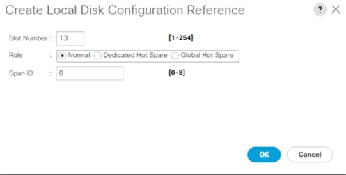
k. For Slot 14, Select Role as Global Hot Spare and Span Id as unspecified.
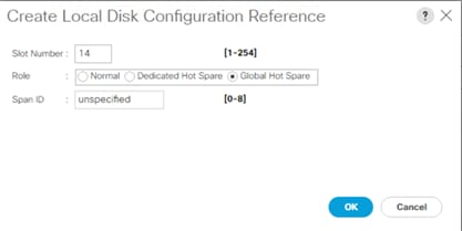
l. Repeat steps d and e, for Slot 15 to Slot 27 and enter Span ID as 1.
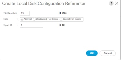
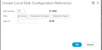
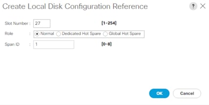
m. For Slot 28, select Role as Global Hot Spare and leave the Span ID as unspecified.
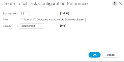
n. Configure Virtual Drive Configuration as detailed below:
i. Select Strip Size as 256KB
ii. Access Policy as Read Write
iii. Read Policy as Read Ahead
iv. Write Cache Policy as Write Back Good BBU
v. IO Policy as Direct
vi. Drive Cache Policy as Platform Default
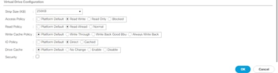
o. Click OK and then click Save the Disk Group Policy. The Disk Group Policy with RAID 60 for 1-28 drives is shown below:
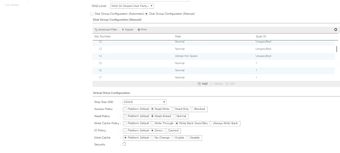
p. Create a third Disk Group Policy with RAID 60, with drives on slot 29-56. Name the Disk Group Policy as ‘S3260_RD60_29-56:
i. For 28 DISK configurations of RAID60, we would have 2 SPANs and each SPAN would have 13 disks.
ii. Remaining 2 DISK are allocated for Global Hot Spares.
iii. For the name enter S3260_RD60-29-56, Select RAID60 from RAID Level and opt for Manual Disk Group Configuration.
iv. Click Add, Enter Slot Number as 29, Role as Normal and Span ID as 0.
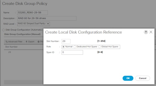
q. Repeat step d, for Slot numbers 30 to 41 with Span ID 0.
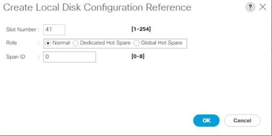
r. For Slot 42, select Role as Global Hot Spare and Span Id as unspecified.
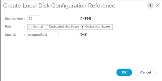
s. Repeat steps d and e, for Slot 43 to Slot 55 and enter Span ID as 1.

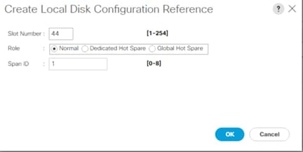
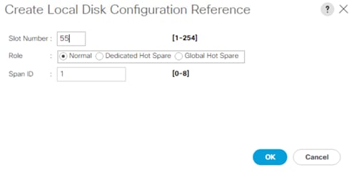
t. For Slot 56, select Role as Global Hot Spare and leave the Span ID as unspecified.

u. Enter the information for the Virtual Drive Configuration:
i. Select Strip Size as 256KB
ii. Access Policy as Read Write
iii. Read Policy as Read Ahead
iv. Write Cache Policy as Write Back Good BBU
v. IO Policy as Direct
vi. Drive Cache Policy as Platform Default

v. Click OK and click Save. The disk group policy with the RAID 60 for 1-28 drives is shown below:
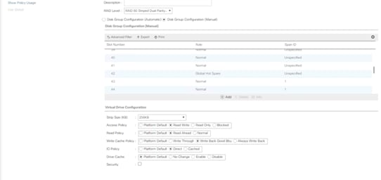
Table 8 lists the RAID configuration and suggested virtual drive configuration for Cisco UCS S3260 Storage Server and Cisco UCS C240 LFF Rack Server.
Table 8. RAID Configuration for Cisco UCS S3260 and Cisco UCS C240 M5 LFF Server
|
|
Small – 1 |
Small – 2 |
Medium -1 |
Medium -2 |
Large -1 |
Large-2 |
Max performance |
| Raw Capacity |
96 TB |
144 TB |
140TB |
280 TB |
560 TB |
1680 TB |
45 TB |
| Storage |
12 x 8-TB SAS 7200-rpm drives
96 TB raw capacity |
12 x 12-TB SAS 7200-rpm drives
144 TB raw capacity |
14 x 10-TB SAS 7200-rpm drives
140 TB raw capacity |
28 x 10-TB SAS 7200-rpm drives
280 TB raw capacity |
56 x 10-TB SAS 7200-rpm drives
560 TB raw capacity |
168 x 10-TB SAS 7200-rpm drives
1680 TB raw capacity |
24 X 1.9 Enterprise Value SATA SSD
45 TB raw capacity
|
| Servers |
1 Cisco UCS C240 M5 (LFF) |
1 Cisco UCS C240 M5 (LFF) |
1 Cisco UCS S3260 |
1 Cisco UCS S3260 |
1 Cisco UCS S3260 |
3x Cisco UCS S3260 |
1x C240 All Flash Rack Server |
| CPU |
Intel Xeon processor 4214R (12 cores, 2.4 GHz, and 100W) |
Intel Xeon processor 4214 (12 cores, 2.3 GHz, and 105W) |
Intel Xeon processor 6226R (32 cores, 2.9 GHz, and 150W) |
Intel Xeon processor 6226R (32 cores, 2.9 GHz, and 150W) |
Intel Xeon processor 6226R (32 cores, 2.9 GHz, and 150W) |
Intel Xeon processor 6226R (96 cores, 2.9 GHz, and 150W) |
Intel Xeon processor 6226R (32 cores, 2.9 GHz, and 150W) |
| Memory |
128 GB |
128 GB |
384 GB |
384 GB |
384 GB |
384 GB per server |
384 GB |
| RAID Cache |
2 GB |
2 GB |
2 x 4GB |
2 x 4GB |
2 x 4 GB |
2 x 4 GB |
2 GB |
| RAID |
RAID 6 |
RAID 6 |
RAID 60 |
RAID 60 |
RAID 60 |
2 x RAID 60 |
RAID 6 |
| Maximum Bandwidth |
2x 40 Gbps 4x 25 Gbps |
2x 40 Gbps 4x 25 Gbps |
2x 40 Gbps 4x 25 Gbps |
2x 40 Gbps 4x 25 Gbps |
2x 40 Gbps 4x 25 Gbps |
2x 40 Gbps 4x 25 Gbps |
2x 40 Gbps 4x 25 Gbps |
Create Storage Profile for Cisco UCS S3260 Storage Server
To create Storage Profile for Cisco UCS S3260, follow these steps:
1. In Cisco UCS Manager, click the Storage tab in the navigation pane.
2. Select Storage Profiles > root >Sub-Organizations >Backup_Infra_Org.
3. Right-click and select Create Storage Profile.
4. For the name enter S3260_Str_Prf_1.
5. Click Add.

6. For the name enter OS_Boot.
7. Check Expand to Available; this creates a single lun with maximum space available.
8. From the Select Disk Group Configuration drop-down list, select S3260_Raid1_OS and click OK.
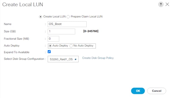
9. Click Add.
10. For the name enter Veeam_Rep1; this is the LUN used by Veeam Repository created on RAID60 volume across disk slot 1-28
11. Check Expand to Available and From the Select Disk Group Configuration drop-down list, select S3260_RD60-1-28.
12. Click OK.
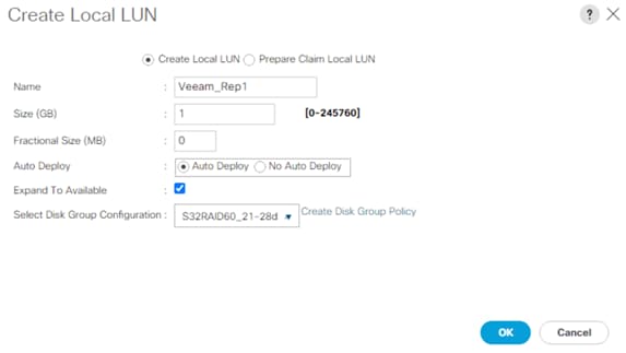
13. Click Add.
14. For the name enter Veeam_Rep2; this is the LUN used by Veeam Repository created on RAID60 volume across disk slot 29-56.
15. Check Expand to Available and from the Select Disk Group Configuration drop-down list, select S3260_RD60-1-28.
16. Click OK.
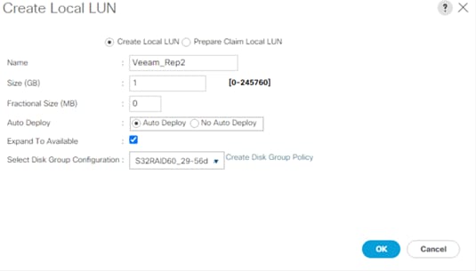
17. Click OK.
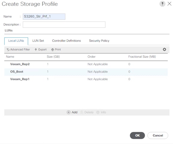
Create Disk Group Policy for Cisco UCS C240 All Flash Rack Server
![]() This section only applies to a deployment when customers deploy Cisco UCS C240 All Flash Server as Veeam Backup and Replication Server with local backup repository.
This section only applies to a deployment when customers deploy Cisco UCS C240 All Flash Server as Veeam Backup and Replication Server with local backup repository.
Create a Disk Group Policy for Cisco UCS C240 All Flash Server with the following:
● RAID 1 from two Rear SSDs for OS Boot
● RAID6 for front 24 SSD drives
Table 9 lists the RAID Policies which can be configured on Cisco UCS C240 All Flash rack server.
Table 9. RAID Group Configuration on Cisco UCS S3260
| # Disk |
RAID Group |
# SPANs |
# Disk per SPAN |
# Global Hot Spares |
| 24 |
RAID 6 |
NA |
NA |
1 |
To create Disk Group Policy, follow these steps:
1. In Cisco UCS Manager, click the Storage tab in the navigation pane.
2. Select Storage Policies > root >Sub-Organizations > Backup_Infra_Org >Disk Group Policies.
3. Right-click the Disk Group Policy and select Create Disk Group Policy.
4. For the name enter C240AFF_RAID1_OS.
5. Select RAID Level as RAID1 Mirrored.
6. Select Disk Group Configuration (Manual).
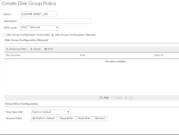
7. Click Add and for the Slot number enter 25 then click OK.
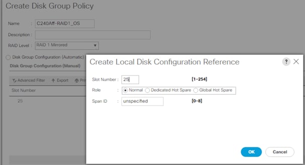
8. Click Add and for the Slot number enter 26 the click OK.
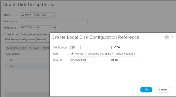
9. Strip Size = 64KB, Access Policy = Read Write, Write Cache Policy = Write Back Good BBU, IO Policy = Direct, Drive Cache = Direct.
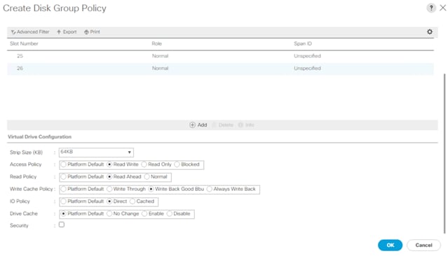
10. Create a second Disk Group Policy with RAID 6. This will be utilized as Veeam Storage Repository.
11. Create a RAID6 with 24 SSDs.
12. For 24 DISK configurations of RAID6, go to Storage Policies > root >Sub-Organizations > Backup_Infra_Org >Disk Group Policies.
13. Right-click Disk Group Policy and select Create Disk Group Policy.
14. For the RAID Level enter Raid6 Striped Dual Parity
15. For the number of drives enter 23, for the Drive Type select SSD and for the Number of Global Hot Spares enter 1. This configuration will utilize 24 disks in the system
16. In Virtual Drive Configuration:
a. For the RAID Level select RAID6 Striped Dual Parity
b. For Use JBOD Disk select Yes
c. For the Strip Size select 256KB
d. For the Access Policy select Read Write
e. For the Read Policy select Read Ahead
f. For the Write Cache Policy select Write Back Good BBU
g. For the IO Policy select Direct
h. For the Drive Cache Policy select Platform Default
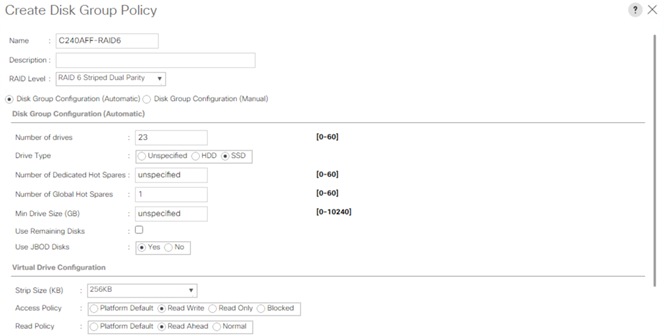
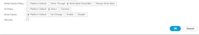
17. Click OK.
Create Storage Profile for Cisco UCS C240 All Flash Rack Server
![]() This section only applies to a deployment when customers deploy Cisco UCS C240 All Flash Server as Veeam Backup and Replication Server with local backup repository.
This section only applies to a deployment when customers deploy Cisco UCS C240 All Flash Server as Veeam Backup and Replication Server with local backup repository.
To create Storage Profile for Cisco UCS C240 Rack Server equipped with 24 front SSD and 2 Rear SSD for Boot, follow these steps:
1. In Cisco UCS Manager, click the Storage tab in the navigation pane.
2. Go to Storage Profiles > root >Sub-Organizations >Backup_Infra_Org.
3. Right-click and click Create Storage Profile.
4. For the name enter C240AFF_Str_Prf1.
5. Click Add.
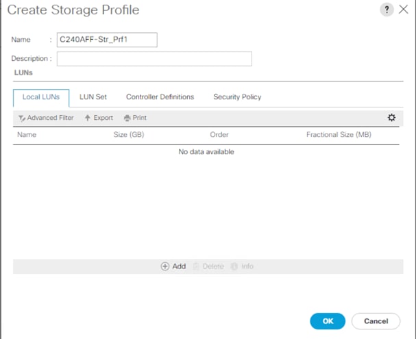
6. For the name enter OS_Boot.
7. Check Expand to Available; this creates a single LUN with maximum space available.
8. For Select Disk Group Configuration, select C240Aff-Raid1_OS and click OK.
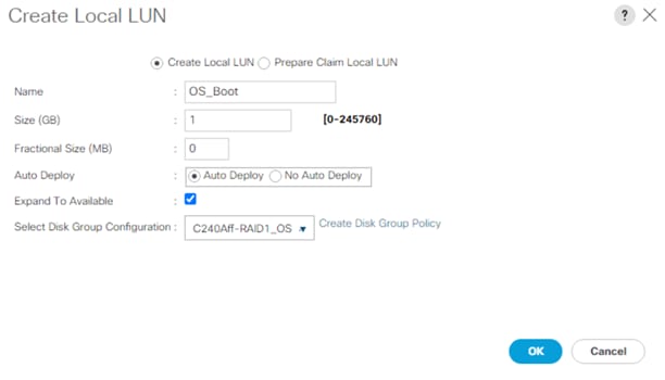
9. Click Add.
10. For the name enter Veeam_Rep; this is the LUN used by Veeam Repository.
11. Check Expand to Available and for the Select Disk Group Configuration, select C240AFF-RAID6.
12. Click OK.
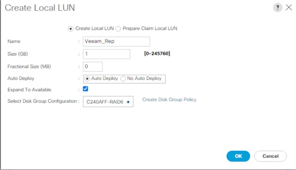
i. Click OK.
Configure Cisco UCS C240 All Flash Rack Server
This section details the configuration of the Cisco UCS Service Profiles Templates and Cisco UCS Service Profiles specific to the Cisco UCS C240 All Flash Rack Server.
Create a Service Profile Template for Cisco UCS C240 All Flash Rack Server
With a service profile template, you can quickly create several service profiles with the same basic parameters, such as the number of vNICs and vHBAs, and with identity information drawn from the same pools.
![]() If you need only one service profile with similar values to an existing service profile, you can clone a service profile in the Cisco UCS Manager GUI.
If you need only one service profile with similar values to an existing service profile, you can clone a service profile in the Cisco UCS Manager GUI.
For example, if you need several service profiles with similar values to configure servers to host database software, you can create a service profile template, either manually or from an existing service profile. You then use the template to create the service profiles.
Cisco UCS supports the following types of service profile templates:
● Initial template: Service profiles created from an initial template inherit all the properties of the template. However, after you create the profile, it is no longer connected to the template. If you need to make changes to one or more profiles created from this template, you must change each profile individually.
● Updating template: Service profiles created from an updating template inherit all the properties of the template and remain connected to the template. Any changes to the template automatically update the service profiles created from the template.
To create the service profile template, follow these steps:
1. In Cisco UCS Manager, click the Servers tab in the navigation pane.
2. Go to Service Profile Templates > root >Sub-Organizations > Backup_Infra_Org.
3. Right-click the Sub Organization.
4. Select Create Service Profile Template to open the Create Service Profile Template wizard.
5. Enter C240AFF_SP_Template1 for the name of the service profile template.
6. Select the option Updating Template.
7. Under UUID, select UUID_Pool for the UUID pool.
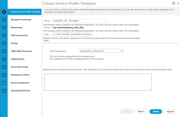
8. Click Next.
9. Under Storage Provisioning, click the Storage Profile Policy Tab and select C240Aff-Str_Prf1 (previously created).
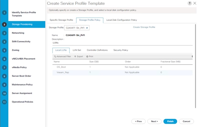
10. Click Next.
11. Under Network, keep the default setting for Dynamic vNIC Connection Policy.
12. For How would you like to configure LAN connectivity, select Expert Mode. Click Add.
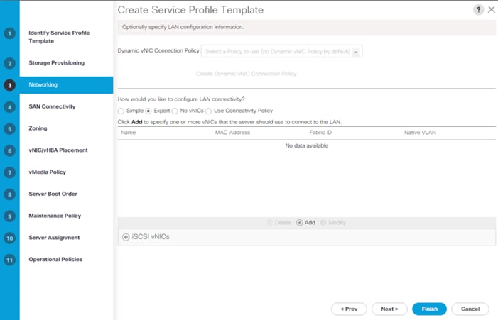
13. Click Add.
14. Under the Create vNIC option, for the name enter vnic_Mgmt.
15. Select use vNIC Template and choose vNICTemplate_A.
16. Under Adapter Policy, select veeam_adaptorpol and click OK.
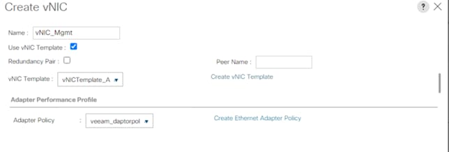

Table 10 lists the details of vNIC.
| vNIC |
Description |
| vnic_mgmt |
Required to manage the Veeam Backup and Replication Server, connect to vCenter, ESXi Host and Pure Storage FlashArray//X management. |
17. Click Next.
18. In the SAN Connectivity menu, select Expert to configure as SAN connectivity. Select BackupInfra_WWNN (WWNN (World Wide Node Name) pool, which you previously created. Click Add to add vHBAs.
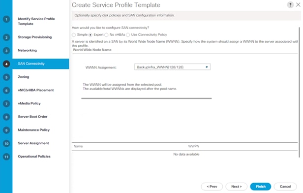
The following two HBAs are created. Select the adapter Policy ‘Veeam_fc_adp_pol’.
● vHBA0 using vHBA Template vHBA-A
● vHBA1 using vHBA Template vHBA-B
Figure 41. vHBA0
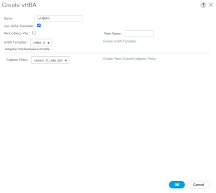
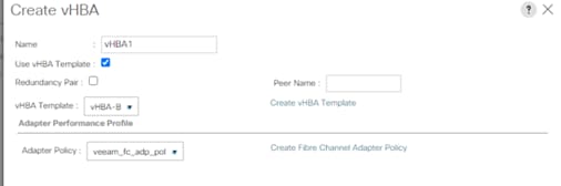
Figure 43. All vHBAs
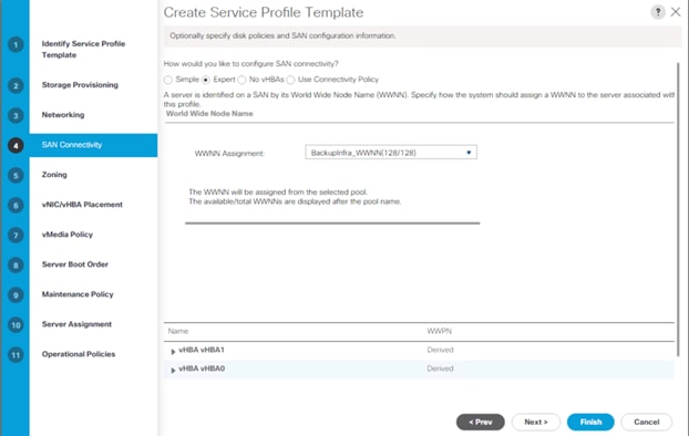
19. Skip zoning. For this configuration, the Cisco MDS 9132T 32-Gb is used for zoning.
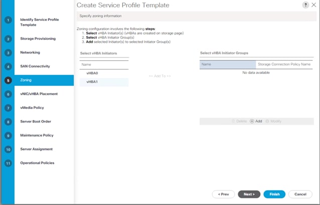
20. In the Select Placement list, leave the placement policy as Let System Perform Placement.
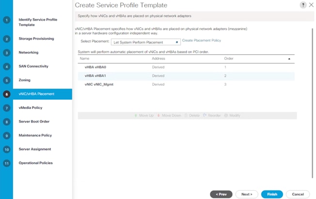
21. Click Next.
22. From the vMedia Policy, leave as default.
23. Click Next.
24. Choose Default Boot Policy.
25. Under Maintenance Policy, change the Maintenance Policy to UserAck.
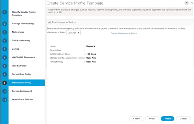
26. Click Next.
27. In the Pool Assignment list, leave it as Assign Later.
28. Under Firmware Management, select BackupInfra_FMW.
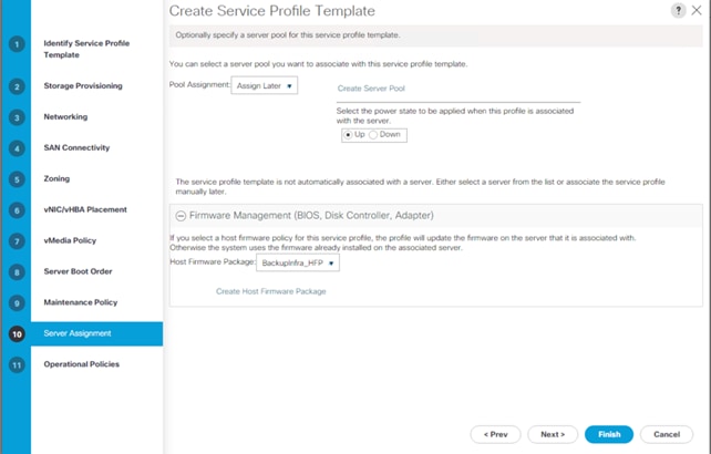
29. Click Next.
30. Configure the Operational Policies:
a. From the BIOS Policy list, select BackupInfra_BIOS.
b. Expand the Power Control Policy Configuration and from the Power Control Policy list select NoPowerCap.
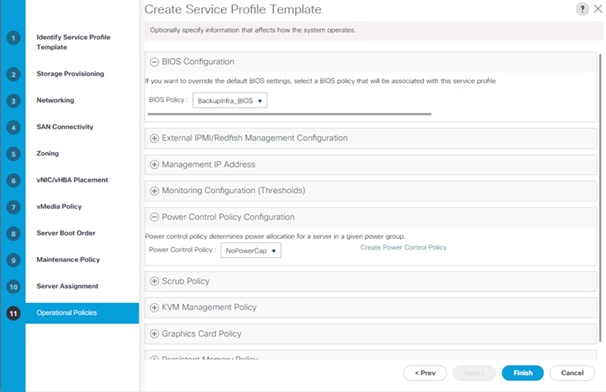
c. Expand Management IP address and select BackupInfra_KVMPool.
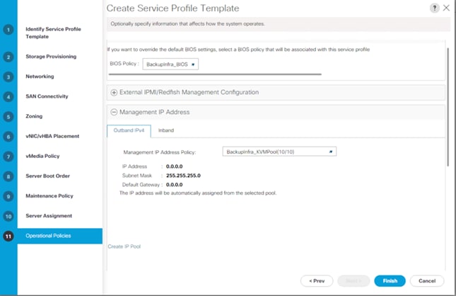
d. Click Finish to create the service profile template.
e. Click OK.
Clone and Associate Service Profile from Template to Cisco UCS C240 All Flash Rack Server
To clone the Service Profile template, follow these steps:
1. In the Cisco UCS Manager, go to Servers > Service Profile Templates > root > Sub Organization > Backup_Infra_Org > Service Template C240AFF_SP_Template1 and right-click Create a Clone as shown below.
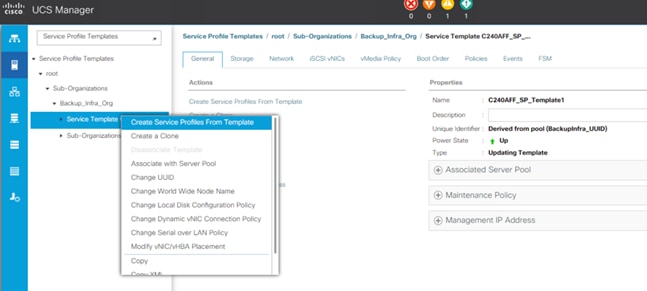
2. Enter the Naming Prefix, Name Suffix Starting Number, and Number of Instance. In this solution, we are creating a Service Profile for one Cisco UCS C240 All Flash Rack Server. Click OK.
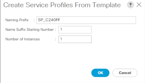
![]() Since we didn’t create a Server Pool, we manually associated the Service Profile (SP_C240AFF1) to the available Cisco UCS C240 All Flash Rack Server.
Since we didn’t create a Server Pool, we manually associated the Service Profile (SP_C240AFF1) to the available Cisco UCS C240 All Flash Rack Server.
3. In the Cisco UCS Manager, go to Servers > Service Profile > root > Sub Organization > Backup_Infra_Org > SP_C240AFF1 and right-click and select change Service Profile Association.
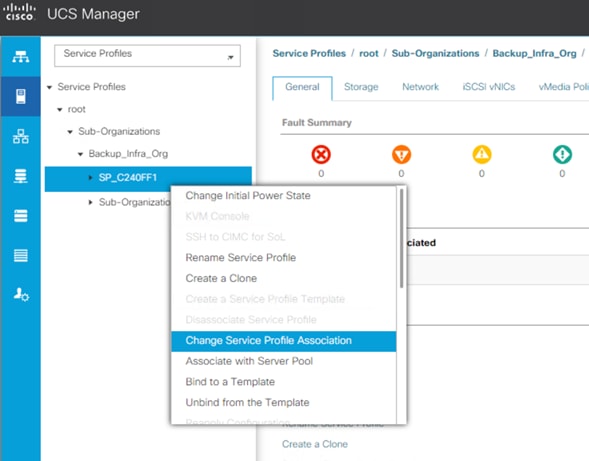
4. In Server Assignment drop-down list, select Existing Server and select UCSC-C240-M5SX server.
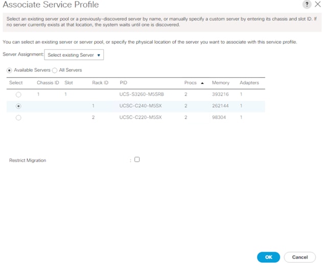
5. Click OK.
You can see the Service Profile Association Status in the FSM tab.
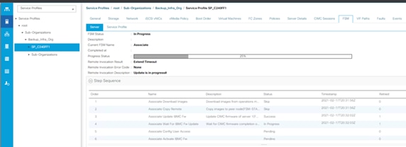
6. Verify the server is associated and the Firmware is upgraded to 4.1(2b) as defined in the Host Firmware Package.
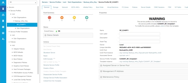
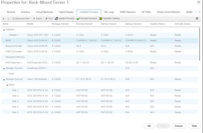
Cisco UCS S3260 Storage Server Configuration
This section details configuration of Cisco UCS Chassis/Service Profiles Templates and Cisco UCS Chassis/Service Profiles specific to Cisco UCS S3260 Storage Server.
Create Chassis Profile Template
A chassis profile defines the storage, firmware, and maintenance characteristics of a chassis. A chassis profile includes four types of information:
● Chassis definition—Defines the specific chassis to which the profile is assigned.
● Maintenance policy—Includes the maintenance policy to be applied to the profile.
● Firmware specifications—Defines the chassis firmware package that can be applied to a chassis through this profile.
● Disk zoning policy—Includes the zoning policy to be applied to the storage disks.
To create Chassis Profile Template for Cisco UCS S3260 storage server, follow these steps:
1. In Cisco UCS Manager, click the Chassis tab in the navigation pane.
2. Go to Chassis Profile Templates > root > Sub-Organizations > Backup_Infra_Org.
3. Right-click and select Create Chassis Profile Template.
4. For the name enter S3260_Chs_Tmplte.
5. Select Type as Updating Template.
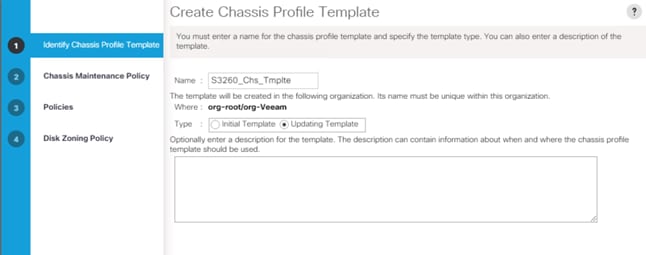
6. Select default for the Maintenance Policy and click Next.
7. For the Chassis Firmware Package, select S3260_FW_Package.
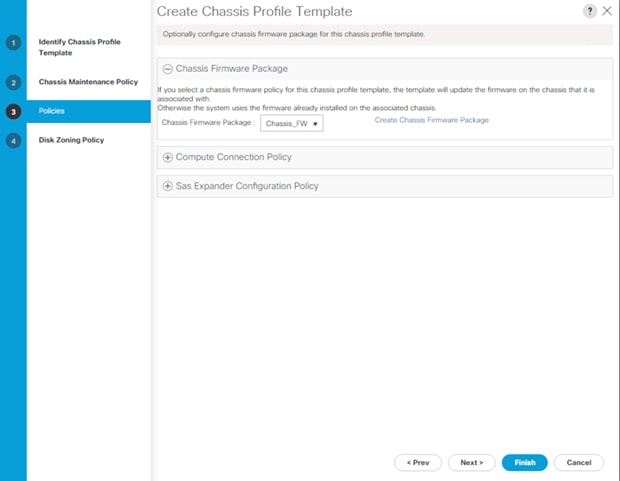
8. For the Disk Zoning Policy, select S3260_DiskZone and click Finish.
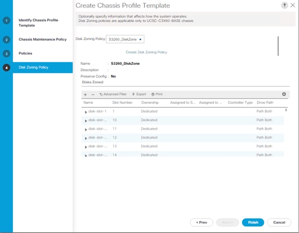
Create a Service Profile Template for Cisco UCS S3260 Storage Server
To create the service profile template for Server node on Cisco UCS S3260 Storage Server, follow these steps:
1. In Cisco UCS Manager, click the Servers tab in the navigation pane.
2. Go to Service Profile Templates > root >Sub-Organizations > Backup_Infra_Org.
3. Right-click the Sub Organization.
4. Select Create Service Profile Template to open the Create Service Profile Template wizard.
5. Enter C240AFF_SP_Template1 for the name of the service profile template.
6. Select the Updating Template option.
7. Under UUID, select UUID_Pool for the UUID pool.
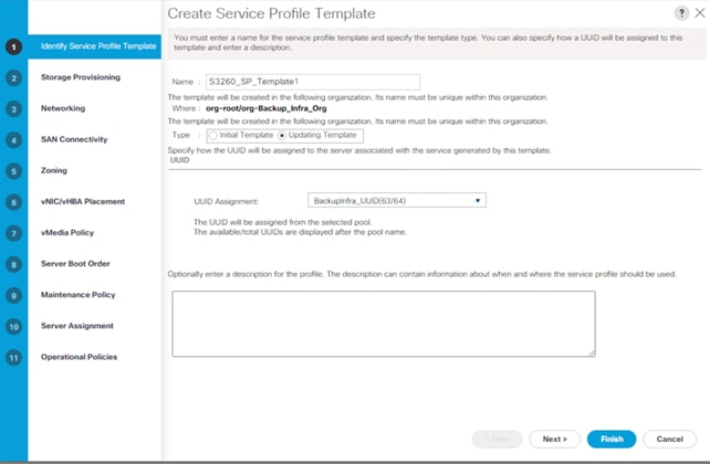
8. Click Next.
9. Under Storage Provisioning, click the Storage Profile Policy tab and select S3260_Str_Prf1_.
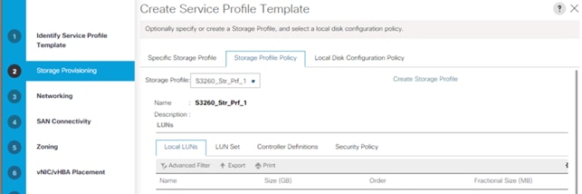
10. Click Next.
11. Under Network, keep the default setting for the Dynamic vNIC Connection Policy.
12. For How would you like to configure LAN connectivity, select Expert Mode. Click Add.
13. Click Add.
14. Under Create vNIC option, for the name enter vnic_Mgmt.
15. Select use vNIC Template and choose vNICTemplate_A.
16. Under Adapter Policy Select veeam_adaptorpol and click OK.

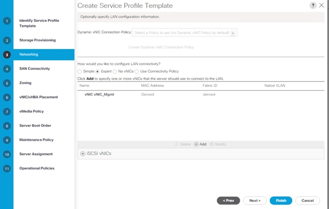
Table 11 lists the details of the configured vNIC.
| vNIC |
Description |
| vnic_mgmt |
Required to manage the Veeam Backup and Replication Serve, connect to vCenter, ESXi Host, and Pure Storage FlashArray//X management. |
17. Click Next.
18. In the SAN Connectivity menu, select Expert to configure as SAN connectivity. Select BackupInfra_WWNN (WWNN (World Wide Node Name) pool, which you previously created. Click Add to add vHBAs.
19. The following two HBAs were created. Select adapter Policy as Veeam_fc_adp_pol:
● vHBA0 using vHBA Template vHBA-A
● vHBA1 using vHBA Template vHBA-B
Figure 44. vHBA0

Figure 45. vHBA1

Figure 46. All vHBAs
20. Skip zoning. For this Configuration, the Cisco MDS 9132T 32-Gb is used for zoning.
21. In the Select Placement list, leave the placement policy as Let System Perform Placement.

22. Click Next.
23. From the vMedia Policy, leave as default.
24. Click Next.
25. Choose Default Boot Policy.
26. Under Maintenance Policy, change the Maintenance Policy to UserAck.
27. Click Next.
28. In the Pool Assignment list, keep Assign Later.
29. From Firmware Management, select BackupInfra_FMW.
30. Click Next.
31. Configure the Operational Policies:
a. In the BIOS Policy list, select BackupInfra_BIOS.
b. Expand the Power Control Policy Configuration and select NoPowerCap from the Power Control Policy list.
c. Expand Management IP address and select BackupInfra_KVMPool.
32. Click Finish to create the service profile template.
33. Click OK.
Create Chassis Profile for Cisco UCS S3260 Storage Server
To create chassis profile from the chassis profile template, follow these steps:
1. Click the Chassis tab in the navigation pane.
2. Go to Chassis Profile Templates > root > Sub-Organizations > Backup_Infra_Org > Chassis Profile Template Chassis_Template.
3. Right-click Chassis Profile Template Chassis_S3260_Chs_Tmplte and select Create Chassis Profiles from Template.
4. Enter S3260_ChassisSP for the Chassis profile prefix.
5. Enter 1 for the Name Suffix Starting Number and 1 as Number of Instances.
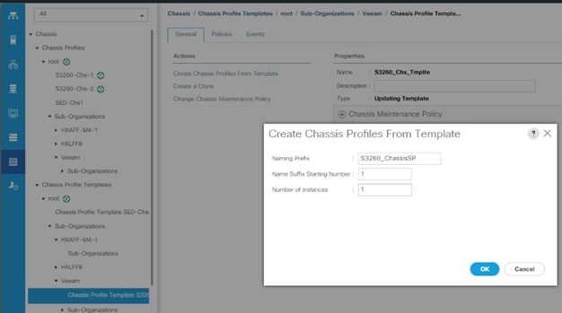
The screenshot below displays the S3260_ChassisSP1 under Chassis > root > Sub-Organizations > Veeam > Chassis Profile.
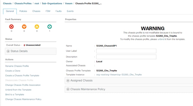
Associate Chassis Profile to Cisco UCS S3260 Chassis
To Associate Chassis Profile to Cisco UCS S3260 Chassis, follow these steps:
1. Click the Chassis tab in the navigation pane.
2. Go to Chassis Profiles > root > Sub-Organizations > Veeam.
3. Right-click S3260_Chassis_SP1 and select Change Chassis Profile Association.
4. In the Assignment tab, select Existing Chassis.
5. Select the existing chassis.
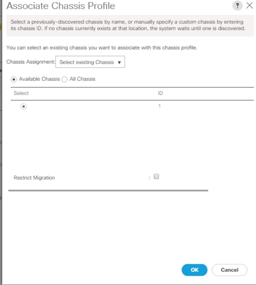
6. Click OK. A user Acknowledgement warning appears, click Yes.
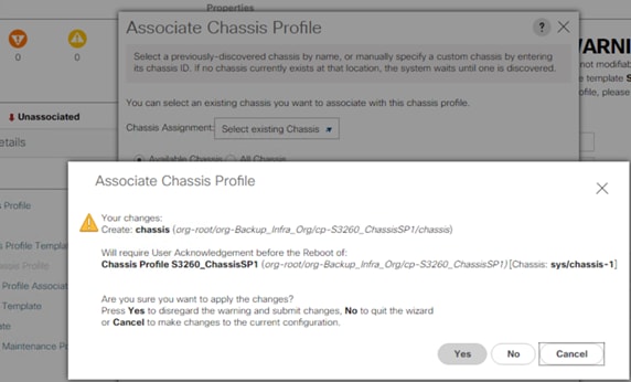
![]() Since you selected User Ack for the Maintenance Policy, you need to acknowledge the Chassis Reboot for Chassis Profile Association.
Since you selected User Ack for the Maintenance Policy, you need to acknowledge the Chassis Reboot for Chassis Profile Association.
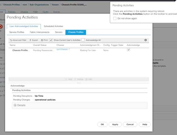
From the FSM tab you can see the Association Status.
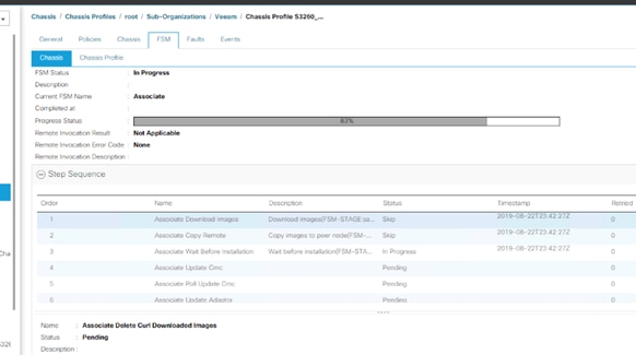
When the Chassis is Associated you will see the assigned status as Assigned.
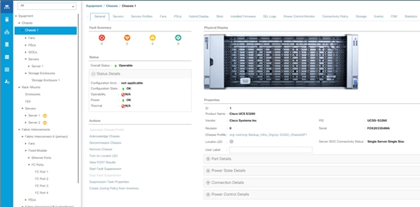
7. Click the Equipment tab and go to Chassis > Chassis 1and then click the Firmware tab. Ensure Chassis Firmware is updated to 4.1(2b) as defined in the Chassis Firmware Package.
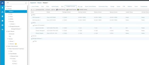
Create Service Profiles for Cisco UCS S3260 Storage Server
This section describes how to create the Service Profile for the Compute Node on the Cisco UCS S3260 Storage server.
To create service profiles from the service profile template, follow these steps:
1. On Servers tab in the navigation pane.
2. Select Service Profile Templates > root > Sub-Organizations > Veeam > Service Template S3260_SP_Template.
3. Right-click S3260_SP_Template and select Create Service Profiles from Template.
4. For the Naming Prefix, enter SP_S3260_node.
5. For the Name Suffix Starting Number, enter 1.
6. For the Number of Instances, enter 1.
7. Click OK to create the service profile.
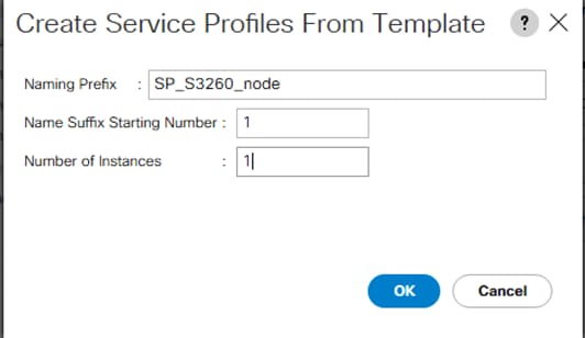
8. Click OK in the confirmation message.
Associate Service Profile to Server Node of Cisco UCS S3260 Chassis
Adding the compute node of the Cisco UCS S3260 chassis to the Server Pool and associated this pool to Service Profile template, the association of server Service Profile to compute node is automatic. If there is no unassociated compute node in the Server Pool, you will need to add a node to server pool which would allow association to Service Profile.
To associate the service profile to the server node of the Cisco UCS S3260 chassis, follow these steps:
1. Go to Server Tab > Servers >Sub Organization > Backup_Infra_Org . Right-click SP_S3260_Profile1. Select Change Service Profile Association option.
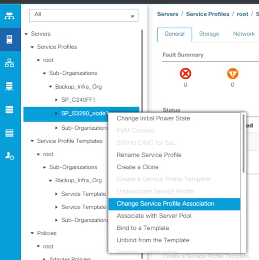
2. From the Server Assignment, select Existing Server from the drop-down list and Select Chassis 1/Slot1 for the compute node. Click OK. A Warning is displayed for creation of Boot Lun on Rear Drives of S3260 chassis. Click Yes.
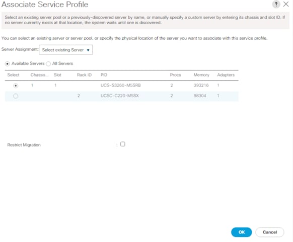
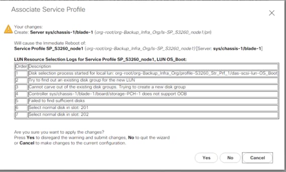
3. Click the FSM tab and monitor the Service Profile Association.
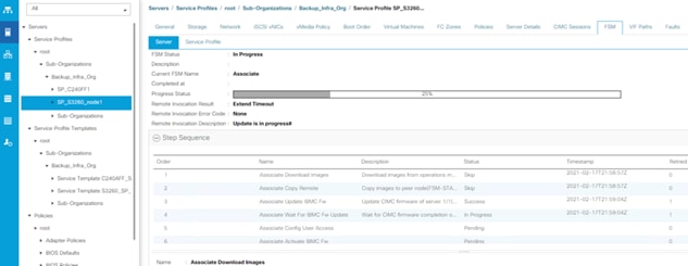
4. When the Service Profile Association is complete, confirm that the overall status is OK.
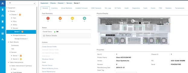
5. Verify the Server node is upgraded with the latest Firmware as detailed in the Host Firmware Package.
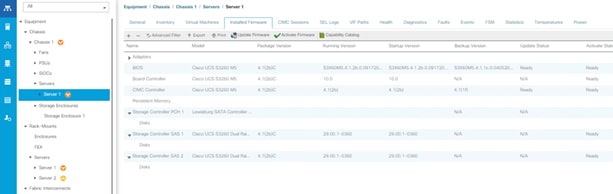
6. Verify the Boot LUN and Veeam Backup Repository LUN under Storage tab of Service Profile.
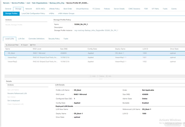
Configure Cisco UCS C220 Server with Pure Storage FlashArray//C as Target Veeam Repository
This section details configuration of Cisco UCS Service Profiles Templates and Cisco UCS Service Profiles specific to Cisco UCS C220 Rack Server with Pure Storage FlashArray//C as the Veeam Backup Repository.
The service profile templates enable policy-based server management that helps ensure consistent server resource provisioning suitable to meet predefined workload needs.
You will create a single Service Profile template; C220-FlashArrayC-Template which uses the boot policy “SAN-A” utilizing FC ports from Pure Storage for high-availability in case the FC links become inaccessible.
Create Service Profile Template
To create a service profile template, follow these steps:
1. In the Cisco UCS Manager, go to Servers > Service Profile Templates > root Sub Organization > Backup_Infra_Org > and right-click Create Service Profile Template.
2. Enter the Service Profile Template name, select the UUID Pool that was previously created and click Next.
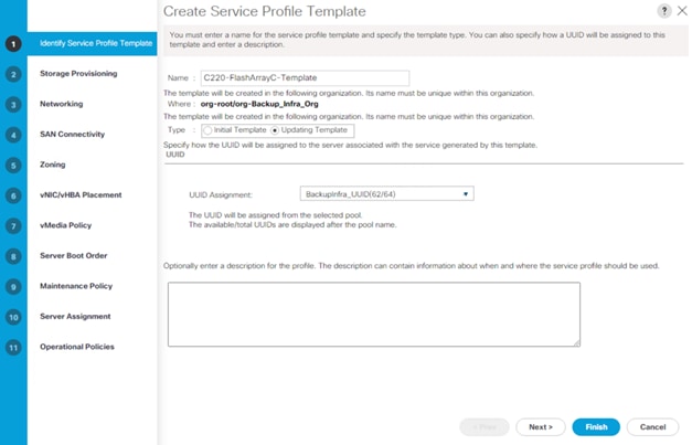
3. From the Local Disk Configuration Policy, for Local Storage select No Local Storage. Ensure there is no local disk in the Cisco UCS C220 rack server.
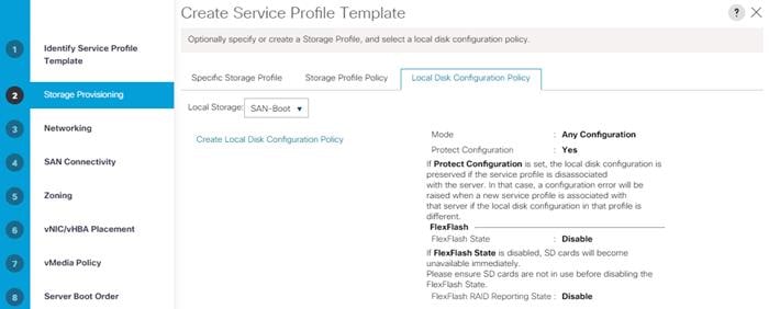
4. In the networking window, select Expert and click Add to create vNICs.
5. For the vNIC Template, select vNIC-Template-A and for the Adapter Policy select veeam_AdaptorPolicy. This vNIC is required to manage the Veeam Backup and Replication Server, connect to vCenter, ESXi Host and Pure Storage FlashArray//X, and Pure Storage FlashArray//C management.
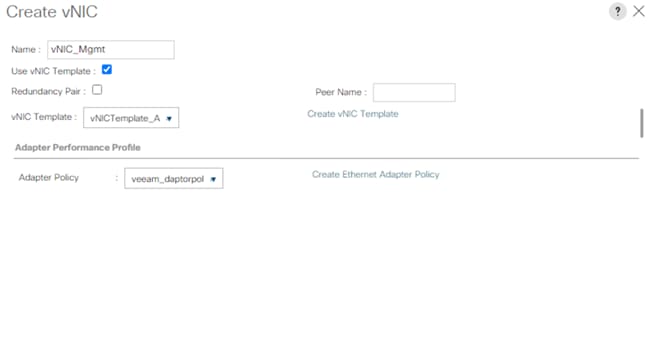
6. When the vNICs are created, you need to create vHBAs. Click Next.
7. In the SAN Connectivity menu, select Expert to configure as SAN connectivity. Select WWNN (World Wide Node Name) pool (BackupInfra_WWNN), which you previously created. Click Add to add vHBAs.
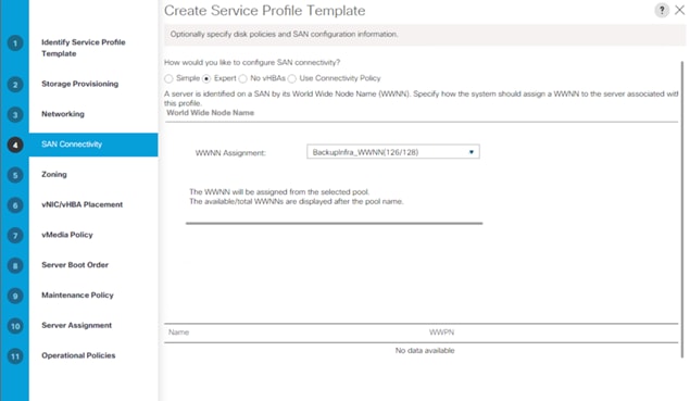
The following four HBAs were created:
● vHBA0 using vHBA Template vHBA-A and adapter Policy as ‘Veeam_FC_ADP_Pol’.
● vHBA1 using vHBA Template vHBA-B and adapter Policy as ‘Veeam_FC_ADP_Pol’.
Figure 47. vHBA0

Figure 48. vHBA1
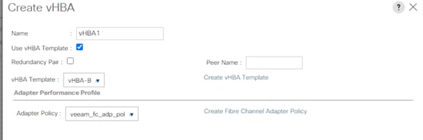
Figure 49. All vHBAs
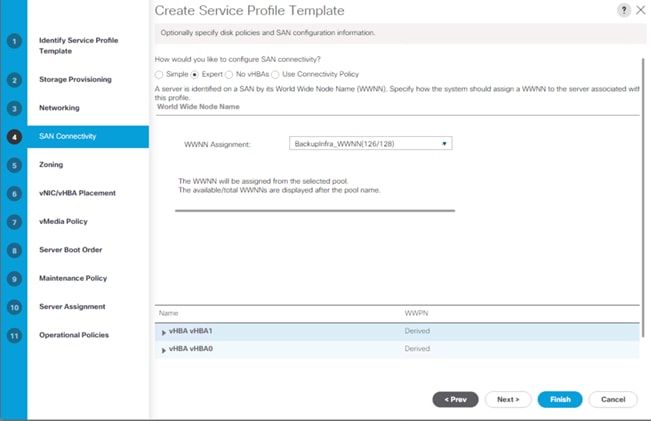
8. Skip zoning. For this solution, the Cisco MDS 9132T 32-Gb is used for zoning.
9. From the Select Placement, select the default option Let System Perform Placement.
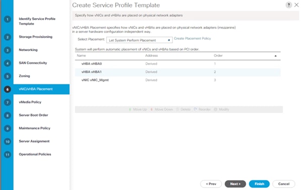
10. For the Server Boot Policy, select SAN-A.
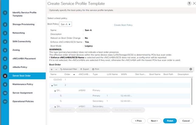
The default setting was retained for the remaining maintenance and assignment policies in the configuration. However, they may vary from site-to-site depending on workloads, best practices, and policies. For example, we created a maintenance policy, BIOS policy, and Power Policy.
11. Select UserAck maintenance policy, which requires user acknowledgement prior rebooting server when making changes to policy or pool configuration tied to a service profile.
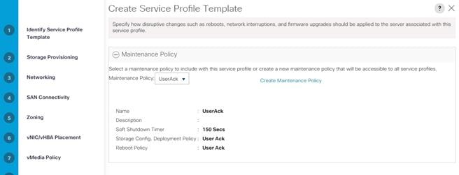
12. On the same page you can configure “Host firmware Package Policy” which keeps the firmware in sync when associated with the server.
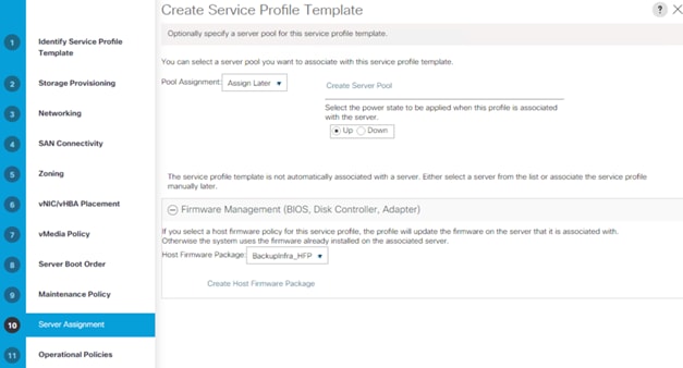
![]() On the Operational Policy page, we configured BIOS policy for Cisco UCS C220 rack server, Power Control Policy with “NoPowerCap” for maximum performance and BackupInfra_KVMPool for Management IP Address .
On the Operational Policy page, we configured BIOS policy for Cisco UCS C220 rack server, Power Control Policy with “NoPowerCap” for maximum performance and BackupInfra_KVMPool for Management IP Address .
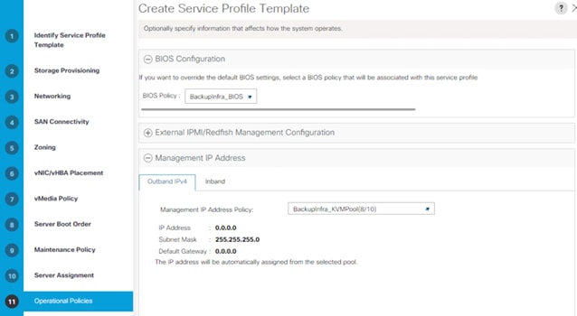
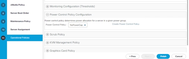
13. Click Finish to create service profile template C220-FlashArrayC-Template.
Create Service Profiles from Template and Associate to Servers
Create Service Profiles from Template
To create Service Profile from Template, follow these steps:
1. Go to the Servers tab > Service Profiles > root > Sub-Organization > Backup_Infra_Org and right-click Create Service Profiles from Template.
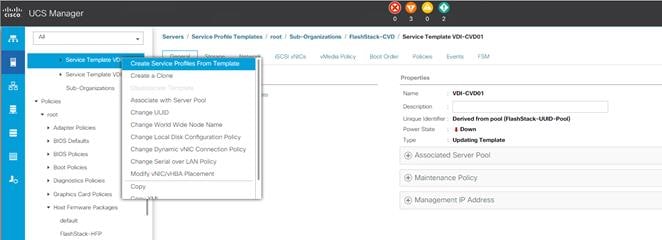
2. Select C220-FlashArrayC-Template for the Service profile template which you created earlier and name the service profile SP-C220-FlashArrayC. To create single service profiles, enter 1 for the Number of Instances.
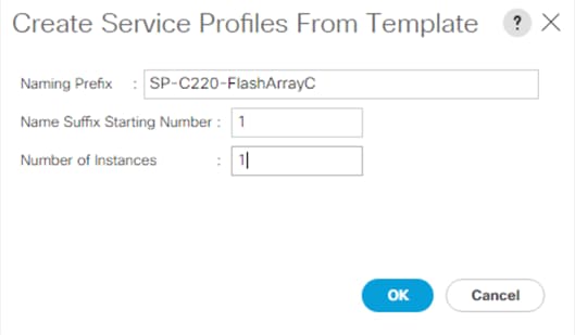
3. When the service profile is created, we would manually associate it to an available C220 server.
![]() In this solution, we used a Cisco UCS C220 M5 server with no local storage as a compute node for the Veeam Backup and Replication Server. This server will boot from SAN and has a Veeam Backup Repository on Pure Storage FlashArray//C. You can use any Cisco UCS B-Series or Cisco UCS C-Series server with no local storage. The CPU and memory configuration of the server should adhere to the performance guidelines from Veeam and Pure Storage.
In this solution, we used a Cisco UCS C220 M5 server with no local storage as a compute node for the Veeam Backup and Replication Server. This server will boot from SAN and has a Veeam Backup Repository on Pure Storage FlashArray//C. You can use any Cisco UCS B-Series or Cisco UCS C-Series server with no local storage. The CPU and memory configuration of the server should adhere to the performance guidelines from Veeam and Pure Storage.
Associate Service Profiles
To associate service profiles, follow these steps:
1. In the Cisco UCS Manager, go to Servers > Service Profile > root > Sub Organization > Backup_Infra_Org > SP-C220-FlashArrayC-1 and right-click and select change Service Profile Association.
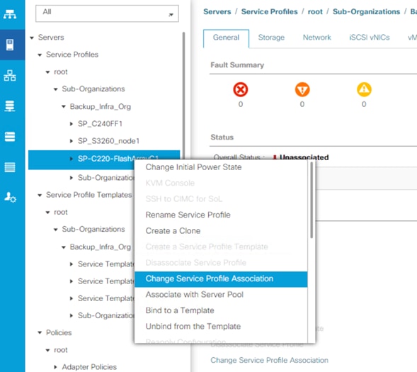
2. From the Server Assignment drop-down list, select Existing Server and select UCSC-C220-M5SX server. Click OK.
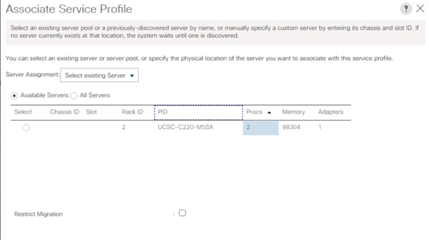
You can verify the Service Profile Association Status in the FSM Tab.
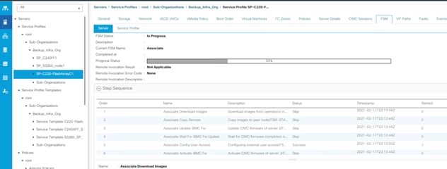
Verify the server is associated and the Firmware is upgraded to 4.1(3b) as defined in the Host Firmware Package.
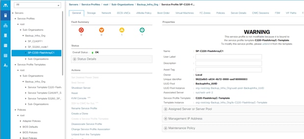
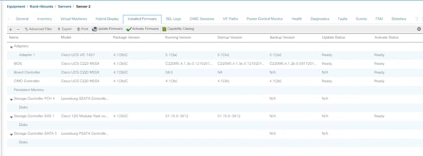
Configure Cisco Nexus 93180YC-FX Switches
The following section details the steps for the Nexus 93180YC-FX switch configuration.
Configure Global Settings for Cisco Nexus A and Cisco Nexus B
To set global configuration, follow these steps on both Cisco Nexus switches:
1. Log in as admin user into the Nexus Switch A and run the following commands to set global configurations and jumbo frames in QoS:
conf terminal
policy-map type network-qos jumbo
class type network-qos class-default
mtu 9216
exit
class type network-qos class-fcoe
pause no-drop
mtu 2158
exit
exit
system qos
service-policy type network-qos jumbo
exit
copy running-config startup-config
2. Log in as admin user into the Nexus Switch B and run the same above commands to set global configurations and jumbo frames in QoS.
Configure VLANs for Cisco Nexus A and Cisco Nexus B Switches
To create the necessary virtual local area networks (VLANs), follow these steps on both Cisco Nexus switches.
![]() We created VLAN 215 and native VLAN 2.
We created VLAN 215 and native VLAN 2.
1. Log in as admin user into the Nexus Switch A.
2. Create VLAN 215:
config terminal
VLAN 215
name IB-MGMT-VLAN
no shutdown
exit
copy running-config startup-config
3. Log in as admin user into the Nexus Switch B and create VLANs.
Virtual Port Channel (vPC) Summary for Data and Storage Network
In the Cisco Nexus 93180YC-FX switch topology, a single vPC feature is enabled to provide HA, faster convergence in the event of a failure, and greater throughput. Cisco Nexus 93180YC-FX vPC configurations with the vPC domains and corresponding vPC names and IDs are listed in Table 12.
| vPC Domain |
vPC Name |
vPC ID |
| 10 |
Peer-Link |
10 |
| 10 |
vPC Port-Channel to FI-A |
125 |
| 10 |
vPC Port-Channel to FI-B |
127 |
As listed in Table 12, a single vPC domain with Domain ID 10 is created across two Cisco Nexus 93180YC-FX member switches to define vPC members to carry specific VLAN network traffic. In this topology, we defined the following vPCs:
● vPC ID 10 is defined as Peer link communication between two Nexus switches in Fabric A and B.
● vPC IDs 125 and 127 are defined for traffic from Cisco UCS fabric interconnects.
Cisco Nexus 93180YC-FX Switch Cabling Details
The following tables list the cabling information.
Table 13. Cisco Nexus 93180YC-FX-A Cabling Information
| Local Device |
Local Port |
Connection |
Remote Device |
Remote Port |
| Cisco Nexus 93180YC-FX Switch A
|
Eth1/35 |
25Gbe |
Cisco UCS fabric interconnect B |
Eth1/45 |
| Eth1/36 |
25Gbe |
Cisco UCS fabric interconnect A |
Eth1/45 |
|
| Eth1/49 |
40Gbe |
Cisco Nexus 93180YC-FX B |
Eth1/49 |
|
| Eth1/50 |
40Gbe |
Cisco Nexus 93180YC-FX B |
Eth1/50 |
|
| MGMT0 |
1Gbe |
Gbe management switch |
Any |
Table 14. Cisco Nexus 93180YC-FX-B Cabling Information
| Local Device |
Local Port |
Connection |
Remote Device |
Remote Port |
| Cisco Nexus 93180YC-FX Switch B
|
Eth1/35 |
25Gbe |
Cisco UCS fabric interconnect B |
Eth1/46 |
| Eth1/36 |
25Gbe |
Cisco UCS fabric interconnect A |
Eth1/46 |
|
| Eth1/49 |
40Gbe |
Cisco Nexus 93180YC-FX A |
Eth1/49 |
|
| Eth1/50 |
40Gbe |
Cisco Nexus 93180YC-FX A |
Eth1/50 |
|
| MGMT0 |
Gbe |
Gbe management switch |
Any |
Cisco UCS Fabric Interconnect 6454 Cabling
The following tables list the FI 6454 cabling information.
Table 15. Cisco UCS Fabric Interconnect (FI) A Cabling Information
| Local Device |
Local Port |
Connection |
Remote Device |
Remote Port |
| Cisco UCS FI-6454-A |
FC 1/1-4 |
32G FC |
Cisco MDS 9132T 32-Gb-A |
FC 1/13-16 |
| Eth1/45 |
25Gbe |
Cisco Nexus 93180YC-FX Switch A |
Eth1/35 |
|
| Eth1/46 |
25Gbe |
Cisco Nexus 93180YC-FX Switch B |
Eth1/35 |
|
| Mgmt 0 |
1Gbe |
Management Switch |
Any |
|
| L1 |
1Gbe |
Cisco UCS FI - A |
L1 |
|
| L2 |
1Gbe |
Cisco UCS FI - B |
L2 |
Table 16. Cisco UCS Fabric Interconnect (FI) B Cabling Information
| Local Device |
Local Port |
Connection |
Remote Device |
Remote Port |
| Cisco UCS FI-6454-B |
FC 1/1-4 |
32Gb FC |
Cisco MDS 9132T 32-Gb-B |
FC 1/13-16 |
| Eth1/45 |
25Gbe |
Cisco Nexus 93180YC-FX Switch A |
Eth1/36 |
|
| Eth1/46 |
25Gbe |
Cisco Nexus 93180YC-FX Switch B |
Eth1/36 |
|
| Mgmt 0 |
1Gbe |
Management Switch |
Any |
|
| L1 |
1Gbe |
Cisco UCS FI - A |
L1 |
|
| L2 |
1Gbe |
Cisco UCS FI - B |
L2 |
Create vPC Peer-Link Between the Two Nexus Switches
To create the vPC Peer-Link, follow these steps:
1. Log in as admin user into the Cisco Nexus Switch A.
![]() For vPC 10 as Peer-link, we used interfaces 49-50 for Peer-Link. You may choose the appropriate number of ports for your needs.
For vPC 10 as Peer-link, we used interfaces 49-50 for Peer-Link. You may choose the appropriate number of ports for your needs.
2. To create the necessary port channels between devices, run the following commands on both Cisco Nexus switches:
config terminal
feature vpc
feature lacp
vpc domain 10
peer-keepalive destination 10.2.164.54 source 10.2.164.53
exit
interface port-channel 10
description VPC peer-link
switchport trunk native vlan 2
switchport trunk allowed vlan 215
spanning-tree port type network
vpc peer-link
exit
interface Ethernet1/49
switchport mode trunk
switchport trunk native vlan 2
switchport trunk allowed vlan 215,1130,1301
channel-group 10 mode active
no shutdown
exit
interface Ethernet1/50
switchport mode trunk
switchport trunk native vlan 2
switchport trunk allowed vlan 215,1130,1301
channel-group 10 mode active
no shutdown
exit
copy running-config startup-config
3. Log in as admin user into the Nexus Switch B and repeat the above steps to configure second Nexus switch.
![]() Make sure to change the peer-keepalive destination and source IP address appropriately for Nexus Switch B.
Make sure to change the peer-keepalive destination and source IP address appropriately for Nexus Switch B.
Create vPC Configuration Between Cisco Nexus 93180YC-FX and Fabric Interconnects
Create and configure vPC 11 and 12 for data network between the Cisco Nexus switches and fabric interconnects.
To create the necessary port channels between devices, follow these steps on both Cisco Nexus switches:
1. Log in as admin user into Nexus Switch A and enter the following:
config terminal
interface port-channel125
description AA11-FS-DP-UCS-a
switchport mode trunk
switchport trunk native vlan 2
switchport trunk allowed vlan 215
spanning-tree port type edge trunk
mtu 9216
state enabled
vpc 125
no shutdown
exit
interface port-channel127
description AA11-FS-DP-UCS-b
switchport mode trunk
switchport trunk native vlan 2
switchport trunk allowed vlan 215
spanning-tree port type edge trunk
mtu 9216
state enabled
vpc 127
no shutdown
exit
interface Ethernet1/35
description AA11-FS-DP-UCS-a:1/45
switchport mode trunk
switchport trunk native vlan 2
switchport trunk allowed vlan 215
mtu 9216
channel-group 125 mode active
no shutdown
exit
interface Ethernet1/36
description AA11-FS-DP-UCS-b:1/45
switchport mode trunk
switchport trunk native vlan 2
switchport trunk allowed vlan 215
mtu 9216
channel-group 127 mode active
no shutdown
exit
copy running-config startup-config
2. Log in as admin user into the Cisco Nexus Switch B and complete the following for the second switch configuration:
config terminal
interface port-channel125
description AA11-FS-DP-UCS-a
switchport mode trunk
switchport trunk native vlan 2
switchport trunk allowed vlan 215
spanning-tree port type edge trunk
mtu 9216
state enabled
vpc 125
no shutdown
exit
interface port-channel127
description AA11-FS-DP-UCS-b
switchport mode trunk
switchport trunk native vlan 2
switchport trunk allowed vlan 215
spanning-tree port type edge trunk
mtu 9216
state enabled
vpc 127
no shutdown
exit
interface Ethernet1/35
description AA11-FS-DP-UCS-a:1/46
switchport mode trunk
switchport trunk native vlan 2
switchport trunk allowed vlan 215
mtu 9216
channel-group 125 mode active
no shutdown
exit
interface Ethernet1/36
description AA11-FS-DP-UCS-b:1/46
switchport mode trunk
switchport trunk native vlan 2
switchport trunk allowed vlan 215
mtu 9216
channel-group 127 mode active
no shutdown
exit
copy running-config startup-config
Verify All vPC Status is Up on Both Cisco Nexus Switches
Figure 50 shows the verification of the vPC status on both Cisco Nexus Switches.
Figure 50. vPC Description for Cisco Nexus Switch A and B
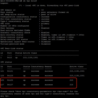
Configure Pure Storage FlashArray//C
FlashArray Initial Configuration
Gather the information listed in Table 17 to enable the installation and configuration of Pure Storage FlashArray//C. An official representative of Pure Storage will help rack and configure the new installation of the FlashArray//C.
Table 17. Startup Configuration for FlashArray//C
| Array Settings |
Variable Name |
| Array Name (Hostname for Pure Array): |
<<var_flasharray_hostname>> |
| Virtual IP Address for Management: |
<<var_flasharray_vip>> |
| Physical IP Address for Management on Controller 0 (CT0): |
<<var_contoller-1_mgmt_ip >> |
| Physical IP Address for Management on Controller 1 (CT1): |
<<var_contoller-2_mgmt_ip>> |
| Netmask: |
<<var_contoller-1_mgmt_mask>> |
| Gateway IP Address: |
<<var_contoller-1_mgmt_gateway>> |
| DNS Server IP Address(es): |
<<var_nameserver_ip>> |
| DNS Domain Suffix: (Optional) |
<<var_dns_domain_name>> |
| NTP Server IP Address or FQDN: |
<<var_oob_ntp>> |
| Email Relay Server (SMTP Gateway IP address or FQDN): (Optional) |
<<var_smtp_ip>> |
| Email Domain Name: |
<<var_smtp_domain_name>> |
| Alert Email Recipients Address(es): (Optional) |
|
| HTTP Proxy Server ad Port (For Pure1): (Optional) |
|
| Time Zone: |
<<var_timezone>> |
![]() When the FlashArray has completed the initial configuration, it is important to configure the Cloud Assist phone-home connection to provide the best proactive support experience possible. Furthermore, this will enable the analytics functionalities provided by Pure1.
When the FlashArray has completed the initial configuration, it is important to configure the Cloud Assist phone-home connection to provide the best proactive support experience possible. Furthermore, this will enable the analytics functionalities provided by Pure1.
The Alerts sub-view is used to manage the list of addresses to which Purity delivers alert notifications, and the attributes of alert message delivery. You can designate up to 19 alert recipients. The Alert Recipients section displays a list of email addresses that are designated to receive Purity alert messages. Up to 20 alert recipients can be designated. The list includes the built-in flasharray-alerts@purestorage.com address, which cannot be deleted.
The email address that Purity uses to send alert messages includes the sender domain name and is comprised of the following components:
<Array_Name>-<Controller_Name>@<Sender_Domain_Name>.com
To add an alert recipient, follow these steps:
1. Click Settings.
2. In the Alert Watchers section, enter the email address of the alert recipient and click the + icon.
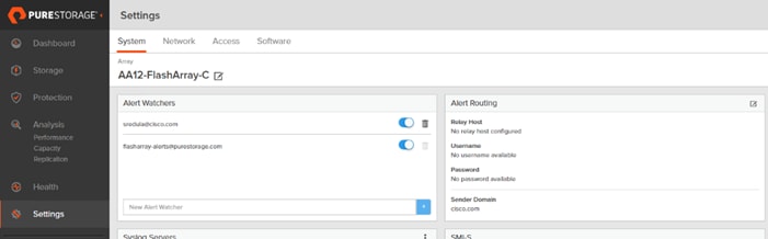
The Relay Host section displays the hostname or IP address of an SMTP relay host if one is configured for the array. If you specify a relay host, Purity routes the email messages via the relay (mail forwarding) address rather than sending them directly to the alert recipient addresses.
In the Sender Domain section, the sender domain determines how Purity logs are parsed and treated by Pure Storage Support and Escalations. By default, the sender domain is set to the domain name please-configure.me.
![]() It is crucial that you set the sender domain to the correct domain name. If the array is not a Pure Storage test array, set the sender domain to the actual customer domain name. For example, mycompany.com.
It is crucial that you set the sender domain to the correct domain name. If the array is not a Pure Storage test array, set the sender domain to the actual customer domain name. For example, mycompany.com.
The Pure1 Support section manages settings for Phone Home, Remote Assist, and Support Logs.
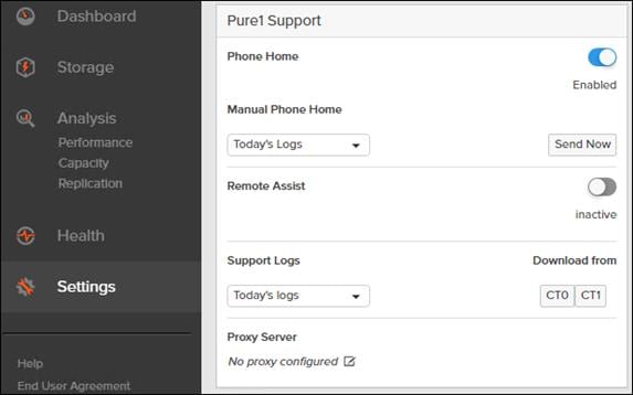
The phone home facility provides a secure direct link between the array and the Pure Storage Technical Support web site. The link is used to transmit log contents and alert messages to the Pure Storage Support team so that when diagnosis or remedial action is required, complete recent history about array performance and significant events is available. By default, the phone home facility is enabled. If the phone home facility is enabled to send information automatically, Purity transmits log and alert information directly to Pure Storage Support via a secure network connection. Log contents are transmitted hourly and stored at the support web site, enabling detection of array performance and error rate trends. Alerts are reported immediately when they occur so that timely action can be taken.
Phone home logs can also be sent to Pure Storage Technical support on demand, with options including Today's Logs, Yesterday's Logs, or All Log History.
The Remote Assist section displays the remote assist status as "Connected" or "Disconnected." By default, remote assist is disconnected. A connected remote assist status means that a remote assist session has been opened, allowing Pure Storage Support to connect to the array. Disconnect the remote assist session to close the session.
The Support Logs section allows you to download the Purity log contents of the specified controller to the current administrative workstation. Purity continuously logs a variety of array activities, including performance summaries, hardware and operating status reports, and administrative actions.
Configure DNS Server IP Addresses
To configure the DNS server IP addresses, follow these steps:
1. Click Settings > Network.
2. In the DNS section, hover over the domain name and click the pencil icon. The Edit DNS dialog box appears.
3. Fill-in the following fields:
a. Domain: Specify the domain suffix to be appended by the array when doing DNS lookups.
b. NS#: Specify up to three DNS server IP addresses for Purity to use to resolve hostnames to IP addresses. Enter one IP address in each DNS# field. Purity queries the DNS servers in the order that the IP addresses are listed.
4. Click Save.
The Directory Service manages the integration of FlashArray with an existing directory service. When the Directory Service sub-view is configured and enabled, the FlashArray leverages a directory service to perform user account and permission level searches. Configuring the directory services is OPTIONAL.
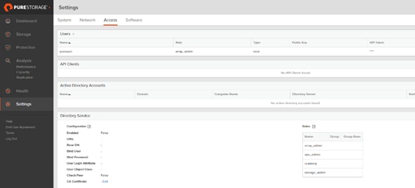
The FlashArray is delivered with a single local user, named pureuser, with array-wide (Array Admin) permissions.
To support multiple FlashArray users, integrate the array with a directory service, such as Microsoft Active Directory or OpenLDAP.
Role-based access control is achieved by configuring groups in the directory that correspond to the following permission groups (roles) on the array:
● Read Only Group. Read Only users have read-only privilege to run commands that convey the state of the array. Read Only uses cannot alter the state of the array.
● Storage Admin Group. Storage Admin users have all the privileges of Read Only users, plus the ability to run commands related to storage operations, such as administering volumes, hosts, and host groups. Storage Admin users cannot perform operations that deal with global and system configurations.
● Array Admin Group. Array Admin users have all the privileges of Storage Admin users, plus the ability to perform array-wide changes. In other words, Array Admin users can perform all FlashArray operations.
1. Click Settings > Access.
2. Click the ![]() icon in the Directory Services panel:
icon in the Directory Services panel:
a. Enabled: Select the check box to leverage the directory service to perform user account and permission level searches.
b. URI: Enter the comma-separated list of up to 30 URIs of the directory servers. The URI must include a URL scheme (ldap, or ldaps for LDAP over SSL), the hostname, and the domain. You can optionally specify a port. For example, ldap://ad.company.com configures the directory service with the hostname "ad" in the domain "company.com" while specifying the unencrypted LDAP protocol.
c. Base DN: Enter the base distinguished name (DN) of the directory service. The Base DN is built from the domain and should consist only of domain components (DCs). For example, for ldap://ad.storage.company.com, the Base DN would be: DC=storage,DC=company,DC=com.
d. Bind User: Username used to bind to and query the directory. For Active Directory, enter the username - often referred to as sAMAccountName or User Logon Name - of the account that is used to perform directory lookups. The username cannot contain the characters " [ ] : ; | = + * ? < > / \ and cannot exceed 20 characters in length. For OpenLDAP, enter the full DN of the user. For example, CN=John,OU=Users,DC=example,DC=com.
e. Bind Password: Enter the password for the bind user account.
f. Group Base: Enter the organizational unit (OU) to the configured groups in the directory tree. The Group Base consists of OUs that, when combined with the base DN attribute and the configured group CNs, complete the full Distinguished Name of each groups. The group base should specify "OU=" for each OU and multiple OUs should be separated by commas. The order of OUs should get larger in scope from left to right. In the following example, SANManagers contains the sub-organizational unit PureGroups: "OU=PureGroups,OU=SANManagers".
g. Array Admin Group: Common Name (CN) of the directory service group containing administrators with full privileges to manage the FlashArray. Array Admin Group administrators have the same privileges as pureuser. The name should be the Common Name of the group without the "CN=" specifier. If the configured groups are not in the same OU, also specify the OU. For example, "pureadmins,OU=PureStorage", where pureadmins is the common name of the directory service group.
h. Storage Admin Group: Common Name (CN) of the configured directory service group containing administrators with storage related privileges on the FlashArray. The name should be the Common Name of the group without the "CN=" specifier. If the configured groups are not in the same OU, also specify the OU. For example, "pureusers,OU=PureStorage", where pureusers is the common name of the directory service group.
i. Read Only Group: Common Name (CN) of the configured directory service group containing users with read-only privileges on the FlashArray. The name should be the Common Name of the group without the "CN=" specifier. If the configured groups are not in the same OU, also specify the OU. For example, "purereadonly,OU=PureStorage", where purereadonly is the common name of the directory service group.
j. Check Peer: Select the check box to validate the authenticity of the directory servers using the CA Certificate. If you enable Check Peer, you must provide a CA Certificate.
k. CA Certificate: Enter the certificate of the issuing certificate authority. Only one certificate can be configured at a time, so the same certificate authority should be the issuer of all directory server certificates. The certificate must be PEM formatted (Base64 encoded) and include the "-----BEGIN CERTIFICATE-----" and "-----END CERTIFICATE-----" lines. The certificate cannot exceed 3000 characters in total length.
3. Click Save.
4. Click Test to test the configuration settings. The LDAP Test Results pop-up window appears. Green squares represent successful checks. Red squares represent failed checks.
Self-Signed Certificate
Purity creates a self-signed certificate and private key when you start the system for the first time. The SSL Certificate sub-view allows you to view and change certificate attributes, create a new self-signed certificate, construct certificate signing requests, import certificates and private keys, and export certificates.
Creating a self-signed certificate replaces the current certificate. When you create a self-signed certificate, include any attribute changes, specify the validity period of the new certificate, and optionally generate a new private key.
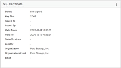
When you create the self-signed certificate, you can generate a private key and specify a different key size. If you do not generate a private key, the new certificate uses the existing key.
You can change the validity period of the new self-signed certificate. By default, self-signed certificates are valid for 3650 days.
CA-Signed Certificate
Certificate authorities (CA) are third party entities outside the organization that issue certificates. To obtain a CA certificate, you must first construct a certificate signing request (CSR) on the array.
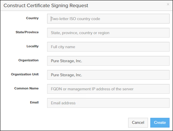
The CSR represents a block of encrypted data specific to your organization. You can change the certificate attributes when you construct the CSR; otherwise, Purity will reuse the attributes of the current certificate (self-signed or imported) to construct the new one. Note that the certificate attribute changes will only be visible after you import the signed certificate from the CA.
Send the CSR to a certificate authority for signing. The certificate authority returns the SSL certificate for you to import. Verify that the signed certificate is PEM formatted (Base64 encoded), includes the "-----BEGIN CERTIFICATE-----" and "-----END CERTIFICATE-----" lines, and does not exceed 3000 characters in total length. When you import the certificate, also import the intermediate certificate if it is not bundled with the CA certificate.
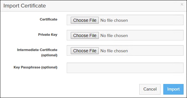
If the certificate is signed with the CSR that was constructed on the current array and you did not change the private key, you do not need to import the key. However, if the CSR was not constructed on the current array or if the private key has changed since you constructed the CSR, you must import the private key. If the private key is encrypted, also specify the passphrase.
Cisco MDS 9132T 32-Gb FC Switch Configuration
Table 18 and Table 19 list the ports utilized between the Cisco MDS 9132T 32-Gb switch and the Cisco 6454 Fabric Interconnects and Pure Storage FlashArray//C storage and FlashArray//X70 R2 production storage array ports used dedicatedly for backup.
![]() We used four 32Gb FC connections from each fabric interconnect to each MDS switch, two 32Gb FC connections from Pure Storage FlashArray//X array controller to each MDS switch and four 32Gb FC connections from Pure Storage FlashArray//C array controller. The FlashStack//X connectivity for production is not discussed in this document, please refer to the FlashStack VSI CVD for detailed information.
We used four 32Gb FC connections from each fabric interconnect to each MDS switch, two 32Gb FC connections from Pure Storage FlashArray//X array controller to each MDS switch and four 32Gb FC connections from Pure Storage FlashArray//C array controller. The FlashStack//X connectivity for production is not discussed in this document, please refer to the FlashStack VSI CVD for detailed information.
Table 18. Cisco MDS 9132T-A Cabling Information
| Local Device |
Local Port |
Connection |
Remote Device |
Remote Port |
| Cisco MDS 9132T-A |
FC1/7 |
32Gb FC |
Pure Storage FlashArray//X 70 R2 Controller 0 |
CT0.FC8 |
| FC1/8 |
32Gb FC |
Pure Storage FlashArray//X 70 R2Controller 1 |
CT1.FC8 |
|
| FC1/29 |
32Gb FC |
Pure Storage FlashArray//C Controller 0 |
CT0.FC0 |
|
| FC1/30 |
32Gb FC |
Pure Storage FlashArray//C Controller 0 |
CT0.FC1 |
|
| FC1/31 |
32Gb FC |
Pure Storage FlashArray//C Controller 1 |
CT0.FC0 |
|
| FC1/32 |
32Gb FC |
Pure Storage FlashArray//C Controller 1 |
CT1.FC1 |
|
| FC1/21 |
32Gb FC |
Cisco 6454 Fabric Interconnect-A |
FC1/1 |
|
| FC1/22 |
32Gb FC |
Cisco 6454 Fabric Interconnect-A |
FC1/2 |
|
| FC1/23 |
32Gb FC |
Cisco 6454 Fabric Interconnect-A |
FC1/3 |
|
| FC1/24 |
32Gb FC |
Cisco 6454 Fabric Interconnect-A |
FC1/4 |
Table 19. Cisco MDS 9132T-B Cabling Information
| Local Device |
Local Port |
Connection |
Remote Device |
Remote Port |
| Cisco MDS 9132T-A |
FC1/7 |
32Gb FC |
Pure Storage FlashArray//X Controller 0 |
CT0.FC9 |
| FC1/8 |
32Gb FC |
Pure Storage FlashArray//X Controller 1 |
CT1.FC9 |
|
| FC1/29 |
32Gb FC |
Pure Storage FlashArray//C Controller 0 |
CT0.FC2 |
|
| FC1/30 |
32Gb FC |
Pure Storage FlashArray//C Controller 0 |
CT0.FC3 |
|
| FC1/31 |
32Gb FC |
Pure Storage FlashArray//C Controller 1 |
CT0.FC2 |
|
| FC1/32 |
32Gb FC |
Pure Storage FlashArray//C Controller 1 |
CT1.FC3 |
|
| FC1/21 |
32Gb FC |
Cisco 6454 Fabric Interconnect-B |
FC1/1 |
|
| FC1/22 |
32Gb FC |
Cisco 6454 Fabric Interconnect-B |
FC1/2 |
|
| FC1/23 |
32Gb FC |
Cisco 6454 Fabric Interconnect-B |
FC1/3 |
|
| FC1/24 |
32Gb FC |
Cisco 6454 Fabric Interconnect-B |
FC1/4 |
Configure Feature for MDS Switch A and MDS Switch B
To set feature on MDS Switches, follow these steps on both MDS switches:
1. Log in as admin user into MDS Switch A:
config terminal
feature npiv
feature telnet
feature fport-channel-trunk
switchname FlashStack-MDS-A
copy running-config startup-config
2. Log in as admin user into MDS Switch B. Repeat the steps above on MDS Switch B.
Configure Individual Ports on Switch A
To configure individual ports and port-channels for Switch A, follow these steps:
1. Log in as admin user into MDS Switch A:
2. From the global configuration mode, run the following commands:
interface fc1/7
switchport description FlashArray-CT0FC8-DP
no shutdown
exit
interface fc1/8
switchport description FlashArray-CT1FC8-DP
no shutdown
exit
interface fc1/21
switchport description AA11-FS-DP-UCS-a:1/1
channel-group 16
no shutdown
exit
interface fc1/22
switchport description AA11-FS-DP-UCS-a:1/2
channel-group 16
no shutdown
exit
interface fc1/23
switchport description AA11-FS-DP-UCS-a:1/3
channel-group 16
no shutdown
exit
interface fc1/24
switchport description AA11-FS-DP-UCS-a:1/4
channel-group 16
no shutdown
exit
interface port-channel16
channel mode active
switchport description AA11-FS-DP-UCS-a
switchport speed 32000
no shutdown
exit
interface fc1/29
switchport description FlashArray-C-CT0FC0
no shutdown
exit
interface fc1/30
switchport description FlashArray-C-CT0FC1
no shutdown
exit
interface fc1/31
switchport description FlashArray-C-CT1FC0
no shutdown
exit
interface fc1/32
switchport description FlashArray-C-CT1FC1
no shutdown
exit
Configure Individual Ports on Switch B
To configure individual ports and port-channels for Switch B, follow these steps:
1. Log in as admin user into MDS Switch B:
2. From the global configuration mode, run the following commands:
interface fc1/7
switchport description FlashArray-CT0FC9-DP
no shutdown
exit
interface fc1/8
switchport description FlashArray-CT1FC9-DP
no shutdown
exit
interface fc1/21
switchport description AA11-FS-DP-UCS-b:1/1
channel-group 16
no shutdown
exit
interface fc1/22
switchport description AA11-FS-DP-UCS-b:1/2
channel-group 16
no shutdown
exit
interface fc1/23
switchport description AA11-FS-DP-UCS-b:1/3
channel-group 16
no shutdown
exit
interface fc1/24
switchport description AA11-FS-DP-UCS-b:1/4
channel-group 16
no shutdown
exit
interface port-channel16
channel mode active
switchport description AA11-FS-DP-UCS-b
switchport speed 32000
no shutdown
exit
interface fc1/29
switchport description FlashArray-C-CT0FC2
no shutdown
exit
interface fc1/30
switchport description FlashArray-C-CT0FC3
no shutdown
exit
interface fc1/31
switchport description FlashArray-C-CT1FC2
no shutdown
exit
interface fc1/32
switchport description FlashArray-C-CT1FC3
no shutdown
exit
Configure VSANs for MDS Switch A and MDS Switch B
To create VSANs, follow these steps:
1. Log in as admin user into MDS Switch A. Create VSAN 102 for Backup Traffic:
config terminal
vsan database
vsan 102
vsan 102 name Backup-Fabric-A
exit
zone smart-zoning enable vsan 102
vsan database
vsan 102 interface fc1/29-32
vsan 102 interface fc1/21-24
vsan 102 interface fc1/7-8
exit
copy running-config startup-config
2. Log in as admin user into MDS Switch B. Create VSAN 202 for Backup Traffic:
config terminal
vsan database
vsan 202
vsan 202 name Backup-Fabric-B
exit
zone smart-zoning enable vsan 202
vsan database
vsan 202 interface fc1/29-32
vsan 102 interface fc1/21-24
vsan 102 interface fc1/7-8
exit
copy running-config startup-config
To create PWWNs of FlashArray//X, FlashArray//C controller ports, and the vHBA ports of the Veeam hosts, follow these steps:
1. Gather the WWPN of the FlashArray adapters using the show flogi database command on each switch and create a spreadsheet to reference when creating device aliases on each MDS.
For MDS 9132T-A:
show flogi database
AA12-FS-9132T-1# sh flogi database
fc1/7 102 0x3a0080 52:4a:93:75:f2:e3:d5:08 52:4a:93:75:f2:e3:d5:08
fc1/8 102 0x3a00a0 52:4a:93:75:f2:e3:d5:18 52:4a:93:75:f2:e3:d5:18
fc1/29 102 0x3a0000 52:4a:93:78:6a:50:04:00 52:4a:93:78:6a:50:04:00
fc1/30 102 0x3a0020 52:4a:93:78:6a:50:04:01 52:4a:93:78:6a:50:04:01
fc1/31 102 0x3a0040 52:4a:93:78:6a:50:04:10 52:4a:93:78:6a:50:04:10
fc1/32 102 0x3a0060 52:4a:93:78:6a:50:04:11 52:4a:93:78:6a:50:04:11
port-channel16 102 0x3a00c0 24:01:00:3a:9c:a4:6e:a0 20:66:00:3a:9c:a4:6e:a1
port-channel16 102 0x3a00c2 20:00:00:25:b5:aa:18:02 20:00:00:25:b5:00:18:02
port-channel16 102 0x3a00c3 20:00:00:25:b5:aa:18:00 20:00:00:25:b5:00:18:00
port-channel16 102 0x3a00c4 20:00:00:25:b5:aa:18:01 20:00:00:25:b5:00:18:01
2. Match these values to their sources from the Purity command line output gained from a ssh connection to the FlashArray//X70 R2 and FlashArray//C using the pureuser account:
pureuser@AA12-FlashArray-C> pureport list
Name WWN Portal IQN NQN Failover
CT0.FC0 52:4A:93:78:6A:50:04:00 - - - -
CT0.FC1 52:4A:93:78:6A:50:04:01 - - - -
CT0.FC2 52:4A:93:78:6A:50:04:02 - - - -
CT0.FC3 52:4A:93:78:6A:50:04:03 - - - -
CT1.FC0 52:4A:93:78:6A:50:04:10 - - - -
CT1.FC1 52:4A:93:78:6A:50:04:11 - - - -
CT1.FC2 52:4A:93:78:6A:50:04:12 - - - -
CT1.FC3 52:4A:93:78:6A:50:04:13 - - - -
3. Match these values to the UCS Service Profile vHBA listing for each host found within Servers > Service Profiles > <Service Profile of Source Host> > Storage > vHBAs:
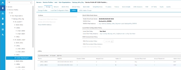
4. Record the values to be used for zoning and host mapping from MDS 9132T A and MDS 9132T B:
Table 20. PWWNs of FlashArray’s and Veeam Hosts on MDS 9132T A
| Switch/Port |
Description |
Customer WWPN/PWWN |
| FC1/7 |
FlashArray//C - CT0.FC0 |
52:4A:93:75:F2:E3:D5:18 |
| FC1/8 |
FlashArray//C - CT0.FC1 |
52:4A:93:75:F2:E3:D5:19 |
| FC1/29 |
FlashArray//C - CT0.FC0 |
52:4A:93:78:6A:50:04:00 |
| FC1/30 |
FlashArray//C - CT0.FC1 |
52:4A:93:78:6A:50:04:01 |
| FC1/31 |
FlashArray//C - CT1.FC0 |
52:4A:93:78:6A:50:04:10 |
| FC1/32 |
FlashArray//C - CT1.FC1 |
52:4A:93:78:6A:50:04:11 |
| port-channel16 |
Veeam-C220-HBA1 |
20:00:00:25:b5:00:18:00 |
| port-channel16 |
Veeam-C240-HBA1 |
20:00:00:25:b5:00:18:01 |
| port-channel16 |
Veeam-S3260-HBA1 |
20:00:00:25:b5:00:18:02 |
Cisco MDS 9132T A
To create device aliases for Fabric A that will be used to create zones, follow this step:
1. Log in as admin user and run the following commands:
device-alias mode enhanced
device-alias database
device-alias name Veeam-C220 pwwn <Veeam-C220-wwpn>
device-alias name Veeam-C240 pwwn <Veeam-C240-wwpn>
device-alias name Veeam-S3260 pwwn <Veeam-C240-wwpn>
device-alias name FlashArray-C-CT0FC0 pwwn <FlashArray-C-CT0FC0-wwpn>
device-alias name FlashArray-C-CT0FC1 pwwn <FlashArray-C-CT0FC1-wwpn>
device-alias name FlashArray-C-CT1FC0 pwwn <FlashArray-C-CT1FC0-wwpn>
device-alias name FlashArray-C-CT1FC1 pwwn <FlashArray-C-CT1FC1-wwpn>
device-alias name FlashArray-CT0FC8-DP pwwn <FlashArray-X-CT0FC8-wwpn>
device-alias name FlashArray-CT1FC8-DP pwwn <FlashArray-X-CT1FC8-wwpn>
device-alias commit
Cisco MDS 9132T B
To create device aliases for Fabric A that will be used to create zones, follow this step:
1. Log in as admin user and run the following commands:
device-alias mode enhanced
device-alias database
device-alias name Veeam-C220 pwwn <Veeam-C220-wwpn>
device-alias name Veeam-C240 pwwn <Veeam-C240-wwpn>
device-alias name Veeam-S3260 pwwn <Veeam-C240-wwpn>
device-alias name FlashArray-C-CT0FC2 pwwn <FlashArray-C-CT0FC2-wwpn>
device-alias name FlashArray-C-CT0FC3 pwwn <FlashArray-C-CT0FC3-wwpn>
device-alias name FlashArray-C-CT1FC2 pwwn <FlashArray-C-CT1FC2-wwpn>
device-alias name FlashArray-C-CT1FC3 pwwn <FlashArray-C-CT1FC3-wwpn>
device-alias name FlashArray-CT0FC9-DP pwwn <FlashArray-X-CT0FC9-wwpn>
device-alias name FlashArray-CT1FC9-DP pwwn <FlashArray-X-CT1FC9-wwpn>
device-alias commit
Create and Configure Fiber Channel Zoning
This procedure sets up the Fibre Channel connections between the Cisco MDS 9132T 32-Gb switches, the Cisco UCS Fabric Interconnects, and the Pure Storage FlashArray//C system.
Cisco MDS 9132T A
To create and configure the fiber channel zoning, follow this step:
1. Log in as admin user and run the following commands:
configure terminal
zone name Veeam-Host-C220 vsan 102
member device-alias Veeam-C220 init
member device-alias FlashArray-C-CT0FC0 target
member device-alias FlashArray-C-CT0FC1 target
member device-alias FlashArray-C-CT1FC0 target
member device-alias FlashArray-C-CT1FC1 target
member device-alias FlashArray-CT0FC8-DP target
member device-alias FlashArray-CT1FC8-DP target
zone name Veeam-Host-C240 vsan 102
member device-alias Veeam-C240 init
member device-alias FlashArray-CT0FC8-DP target
member device-alias FlashArray-CT1FC8-DP target
exit
zone name Veeam-Host-S3260 vsan 102
member device-alias Veeam-S3260 init
member device-alias FlashArray-CT0FC8-DP target
member device-alias FlashArray-CT1FC8-DP target
exit
zoneset name FS-Veeam-Fabric-A vsan 102
member Veeam-Host-C220
member Veeam-Host-C240
member Veeam-Host-S3260
exit
zoneset activate name FS-Veeam-Fabric-A vsan 102
show zoneset active
copy r s
Cisco MDS 9132T B
To create and configure the fiber channel zoning, follow this step:
1. Log in as admin user and run the following commands:
configure terminal
zone name Veeam-Host-C220 vsan 202
member device-alias Veeam-C220 init
member device-alias FlashArray-C-CT0FC2 target
member device-alias FlashArray-C-CT0FC3 target
member device-alias FlashArray-C-CT1FC2 target
member device-alias FlashArray-C-CT1FC3 target
member device-alias FlashArray-CT0FC9-DP target
member device-alias FlashArray-CT1FC9-DP target
exit
zone name Veeam-Host-C240 vsan 202
member device-alias Veeam-C240 init
member device-alias FlashArray-CT0FC9-DP target
member device-alias FlashArray-CT1FC9-DP target
exit
zone name Veeam-Host-S3260 vsan 202
member device-alias Veeam-S3260 init
member device-alias FlashArray-CT0FC9-DP target
member device-alias FlashArray-CT1FC9-DP target
exit
zoneset name FS-Veeam-Fabric-A vsan 202
member Veeam-Host-C220
member Veeam-Host-C240
member Veeaam-Host-S3260
exit
zoneset activate name FS-Veeam-Fabric-B vsan 202
show zoneset active
copy r s
FlashArray Storage Configuration
This section details the following key aspects to configure Data Protection on FlashStack with Veeam:
● Configuration of Pure Storage FlashArray//C for Veeam Backup & Replication Server on C220 Rack Server. This includes creation of Boot Volume and Veeam Backup Repository on FlashArray//C. This is configured on FlashArray//C web portal.
● Registration of Hosts on FlashArray//X deployed on FlashStack environment hosting virtual infrastructure. This includes Cisco UCS S3260 Storage server, Cisco UCS C250 All Flash Rack server, and Cisco UCS C220 Rack server. This step allows restore of Veeam backups in Direct SAN Access Mode. This is configured on FlashArray//X web portal deployed in the FlashStack environment. For more details on Veeam Direct SAN Access Mode, refer Data Restore in Direct SAN Access Mode
Veeam Host Registration on Pure Storage FlashArray//C
To register Veeam Host, allowing access to storage from FlashArray//C for SAN Boot, and Veeam Backup Repository, follow these steps:
1. Host entries can be made from the Pure Storage Web Portal from the STORAGE tab, by selecting the + box under Hosts appearing in the right side of the page:
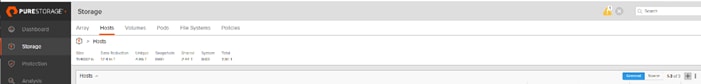
2. After clicking the Create Host option, a pop-up will appear to create an individual host entry on the FlashArray:
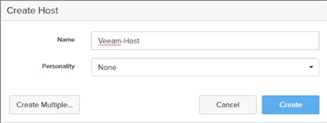
3. Enter the host name and click Create to add the host.
4. For the host previously created, select the host from within the STORAGE tab, and click the Host Ports tab within the individual host view. From the Host Ports tab select the gear icon drop-down and select Configure Fibre Channel WWNs
5. Select the PWWNs of the Veeam Host and click Add.
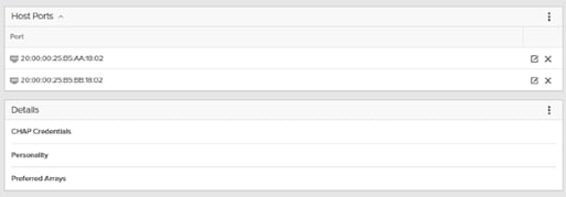
![]() This section is specific for customers using Veeam backup repository on Pure Storage FlashArray//C
This section is specific for customers using Veeam backup repository on Pure Storage FlashArray//C
![]() Make sure the zoning has been setup to include the WWNs details of the initiators along with the target, without which the SAN boot will not work.
Make sure the zoning has been setup to include the WWNs details of the initiators along with the target, without which the SAN boot will not work.
![]() WWNs will appear only if the appropriate FC connections were made, and the zones were setup on the underlying FC switch.
WWNs will appear only if the appropriate FC connections were made, and the zones were setup on the underlying FC switch.
![]() Alternatively, the WWN can be added manually by clicking the + in the Selected WWNs section and manually inputting the blade’s WWNs.
Alternatively, the WWN can be added manually by clicking the + in the Selected WWNs section and manually inputting the blade’s WWNs.
Create Volumes for Veeam Host
Fibre Channel Boot LUNs are mapped on the Pure Storage FlashArray//C using the assigned Initiator PWWN to the provisioned service profiles for Cisco UCS C220 Rack Server. This information can be found within the service profile located within the Cisco UCS Manager. To locate the PWWN within the Service profile, follow these steps:
1. In Cisco UCS Manager, click the Servers tab in the navigation pane.
2. Click Servers > Service Profiles > root > Sub-Organization > Backup_Infra_Org- > SP-C220-FlashArrayC1.
3. Click vHBA.
4. From the right pane, identify the WWPN for vHBA0 and vHBA1, as shown below:
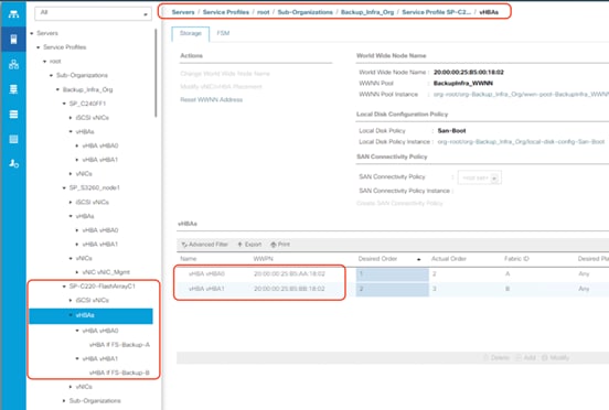
To create private boot volumes for each ESXi Host, follow these steps in the Pure Storage Web Portal:
1. Click Storage > Volumes.
2. Click the + icon in the Volumes Panel.
A pop-up will appear to create a volume on the FlashArray.
3. Enter the Volume name and provisioned for the boot volume.
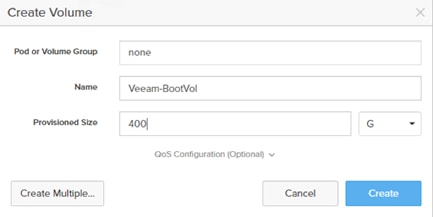
4. Create another volume for Veeam backup repository.
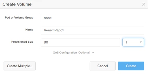
5. Click Create to provision the volume to be used as backup data repository.
6. Go back to the Hosts section under the Storage tab. Click one of Veeam hosts and select the gear icon drop-down list within the Connected Volumes tab within that host.
7. From the drop-down list, select Connect Volumes and a pop-up will appear.
8. Select the Boot and Data repository volumes created earlier and click Connect. Make sure the SAN Boot Volumes has the LUN ID “1” since this is important while configuring Boot from SAN. You will also configure the LUN ID as “1” when configuring Boot from SAN policy in Cisco UCS Manager.
![]() More LUNs can be connected by adding a connection to existing or new volume(s) to an existing node.
More LUNs can be connected by adding a connection to existing or new volume(s) to an existing node.
Veeam Hosts Registration on FlashArray//X 70
To configure Veeam Hosts backup targets registration (Cisco UCS C220 M5, C240 M5, and S3260 M5) to access production storage from FlashArray//X, follow these steps:
1. Host entries can be made from the Pure Storage Web Portal from the STORAGE tab, by clicking the + box under Hosts appearing in the right side of the page:
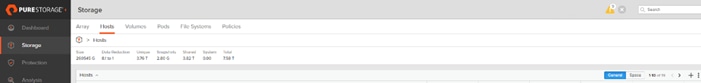
After clicking the Create Host option, a pop-up will appear to create an individual host entry on the FlashArray:
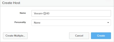
2. Enter the host name and Click Create to add the hosts.
3. Click the Create Host option again to create two additional hosts, the UCS C220 and UCS S3260.
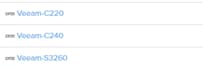
4. For each host created, select the host from within the STORAGE tab, and click the Host Ports tab within the individual host view. From the Host Ports tab click the gear icon drop-down list and select Configure Fibre Channel WWNs
5. Select the PWWNs of the Veeam Hosts and click Add.
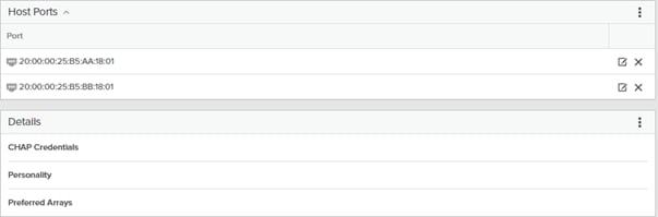
![]() Make sure the zoning has been setup to include the WWNs details of the initiators along with the target, without which the SAN boot will not work.
Make sure the zoning has been setup to include the WWNs details of the initiators along with the target, without which the SAN boot will not work.
![]() WWNs will appear only if the appropriate FC connections were made, and the zones were setup on the underlying FC switch.
WWNs will appear only if the appropriate FC connections were made, and the zones were setup on the underlying FC switch.
![]() Alternatively, the WWN can be added manually by clicking the + in the Selected WWNs section and manually inputting the blade’s WWNs.
Alternatively, the WWN can be added manually by clicking the + in the Selected WWNs section and manually inputting the blade’s WWNs.
Map Production Volumes for Veeam Hosts
VMware datastore LUNs will be mapped to the Veeam Hosts to access production data via SAN.
To map volumes for each Veeam Host, follow these steps in the Pure Storage Web Portal:
1. Go to the Volumes section under the Storage tab. Click one of datastore volumes and click the gear icon drop-down list within the Connected Hosts tab within that volume.
2. From the drop-down list, click Connect, and a pop-up will appear.
3. Select the three Veeam hosts created to access the production data from production FlashStack and click Connect.
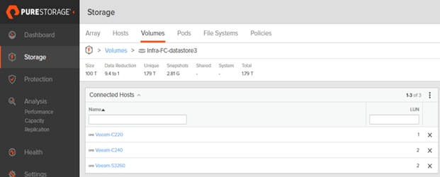
Install and Configure Windows OS
This section explains how to install Windows Server 2019 for the Veeam Backup and Replication Server. This deployment guide describes three different deployments:
● Veeam on Cisco UCS S3260 Storage Server: In this deployment, Windows OS is deployed on the RAID1 volume created on the REAR SSDS of the server. In the configuration section, you can view the details about Virtual Drive creation for Windows OS installation.
● Veeam on Cisco UCS C240 All Flash Rack Server: Similar to Cisco UCS S3260 Storage Server, Windows OS is deployed on the RAID1 volume created on the REAR SSDS of the server.
● Veeam on Cisco UCS C220 Rack Server with Pure Storage FlashArray//C: In this configuration, Cisco UCS C220 Rack Server provides compute with SAN Boot of the Windows OS from Pure Storage FlashArray//C. The Veeam Backup Repository resides on Pure Storage FlashArray//C, mounted as a volume on Windows OS.
Install Windows OS on Cisco UCS S3260 and Cisco UCS C240 Server
To install and configure Windows 2019, follow these steps:
1. In the Navigation pane, click the Server tab.
2. From the Servers tab, expand Service Profiles > root > Sub-Organizations > Backup_Infra_Org >SP_C240AFF1.
3. Click KVM console and select the KVM Out of Band IP.
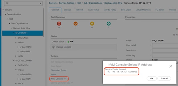
4. In KVM Console, go to the Virtual Media tab and select Activate Virtual Devices.
5. From the Virtual Media tab, click MAP CD/DVD and browse to Windows 2019 Installer and Map Device.

6. Reset the server and wait for the ISO image to load.
7. Install Windows 2019.
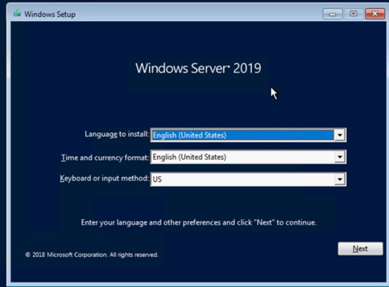
8. Click the Drive0. This drive is RAID1 config created from the two SSD in the rear of S3260 chassis and C240 All Flash rack server.
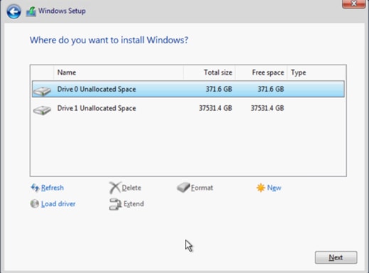
![]() The drive size shown in the figure above is specific to Cisco UCS C240 All Flash Rack Server, Drive size would be different for Cisco UCS S3260 Storage Server.
The drive size shown in the figure above is specific to Cisco UCS C240 All Flash Rack Server, Drive size would be different for Cisco UCS S3260 Storage Server.
9. Click Next and complete Windows 2019 installation.
San Boot Windows OS from Pure Storage FlashArray//C
To install Windows OS through SAN Boot from FlashArray//C, follow these steps:
1. From the Cisco UCS Manager navigation pane, click the Equipment tab.
2. Go to Servers > Service Profiles > root > Sub-Organizations > Backup_Infra_Org > SP-C220-FlashArrayC1
3. Click KVM console and click the KVM Out of Band IP.
4. Click Activate Virtual Devices and then select CD/DVD.
![]()
5. Mount the Windows OS ISO image.
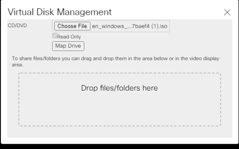
6. Reset the Server and ensure the Pure WWNs are iterated during the sever boot process.
7. Continue with Windows OS Installation. On the Disk selection windows, you will see that no disk is identified for the OS Install. At this point, you need to install the Cisco VIC Fibre Channel driver for Windows 2019.
8. Unmap the Windows ISO.
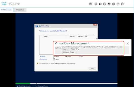
9. Map the Windows driver that can be downloaded from Cisco downloads. Ensure the Windows drivers specific to UCSM 4.1(3b) are used to install Cisco VIC drivers. The drivers can be downloaded from Cisco UCS C Series Windows driver downloads (ucs-cxxx-drivers-windows.4.1.3b.iso)for Firmware 4.1(3b).
10. Click Select drivers and browse to the Cisco VIC Storage drivers for Windows 2019 on the drivers ISO.
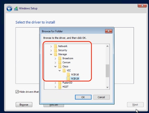
11. Click Rescan and ensure fnic drivers for Windows 2019 are identified.
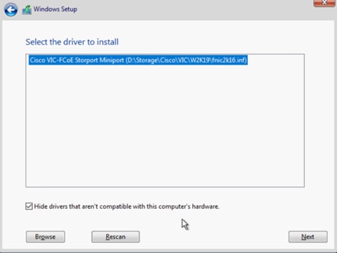
12. Click Next and verify that the Boot volume on Pure Storage FlashArray//C is identified. Select the 400G volume identified for boot.
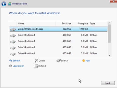
13. Remount the Windows OS ISO and proceed with the OS installation on Cisco UCS C220 rack server with boot volume on FlashArray//C.
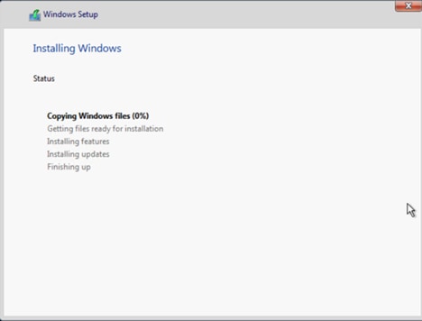
The Windows drivers for Cisco VIC for Cisco UCS 4.1(3b) can be downloaded from Cisco Software Downloads. For detailed steps on updated Cisco enic and fnic drivers, please refer the latest VIC Driver installation guide for Cisco UCS Manager 4.0. Make sure to update the Intel chip set drivers available in the Cisco drivers for windows for Cisco UCS 4.1(3b). When the drivers are updated, the Windows Device Manager should identify the Cisco VIC.
![]() The details of this section is common to Veeam Server Deployments across Cisco UCS S3260 storage server, Cisco UCS C240 All Flash Rack Server, and Cisco UCS C220 Rack server with Fibre Channel connectivity to Pure Storage FlashArray//C.
The details of this section is common to Veeam Server Deployments across Cisco UCS S3260 storage server, Cisco UCS C240 All Flash Rack Server, and Cisco UCS C220 Rack server with Fibre Channel connectivity to Pure Storage FlashArray//C.
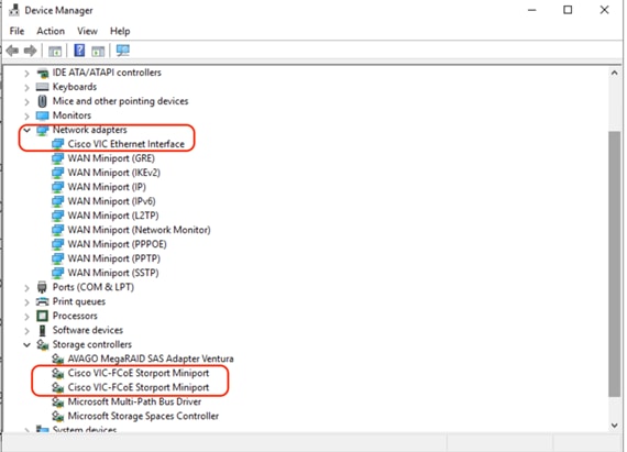
Configure Network for Veeam Backup Server
Adding a management network for each host configured with Veeam Backup & Replication Server is necessary for managing the host. This network should be accessible to the following:
● vCenter Server on FlashStack
● FlashArray//X management network configured on FlashStack deployment
The Network connections for the present setup are displayed below:
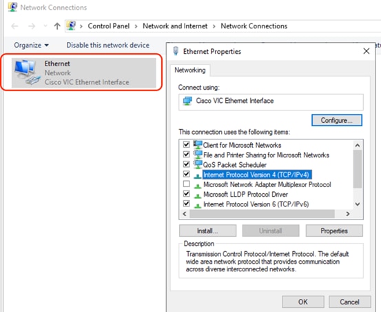
This section explains the key task required to configure the Windows Multipath to allow maximum Fibre Channel throughput and protection from I/O path failures.
![]() The details of this section is common to the Veeam Backup Server Deployments across Cisco UCS S3260 storage server, Cisco US C240 All Flash Rack Server, and Cisco UCS C220 rack server with Fibre Channel connectivity to Pure Storage FlashArray//C.
The details of this section is common to the Veeam Backup Server Deployments across Cisco UCS S3260 storage server, Cisco US C240 All Flash Rack Server, and Cisco UCS C220 rack server with Fibre Channel connectivity to Pure Storage FlashArray//C.
To configure Multipath-IO, follow these steps:
1. Under Windows Server Manager Dashboard, Select Add Roles and Features:
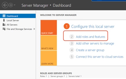
2. Click Next, accept the default settings, and from the Select Server Roles option, check the File and Storage Services.
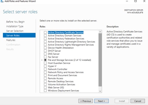
3. Click Next and select Multipath I/O feature.
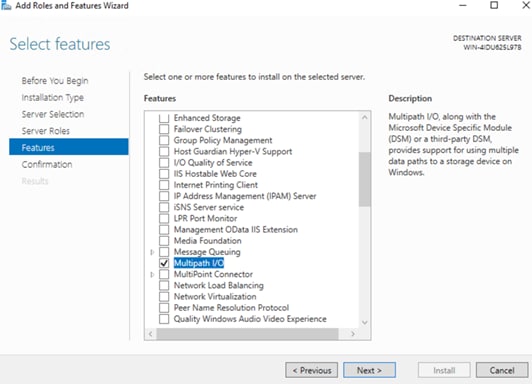
4. Install multipath I/O feature and reboot the Windows Server.
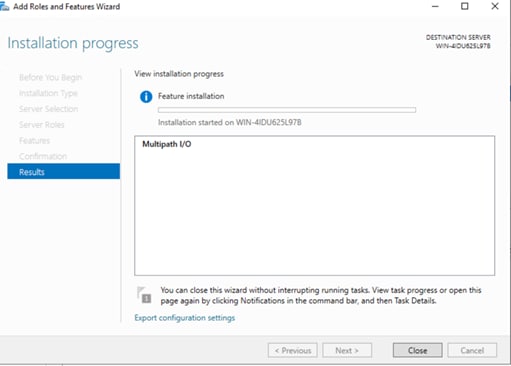
5. When the server comes back online, configure the MPIO specific to Pure Storage FlashArray as detailed in Configuring Multipath-IO for Windows Server (https://support.purestorage.com/Solutions/Microsoft_Platform_Guide/Multipath-IO_and_Storage_Settings/Configuring_Multipath-IO). Confirm proper configuration of Pure Storage FlashArray device under Windows MPIO tool.
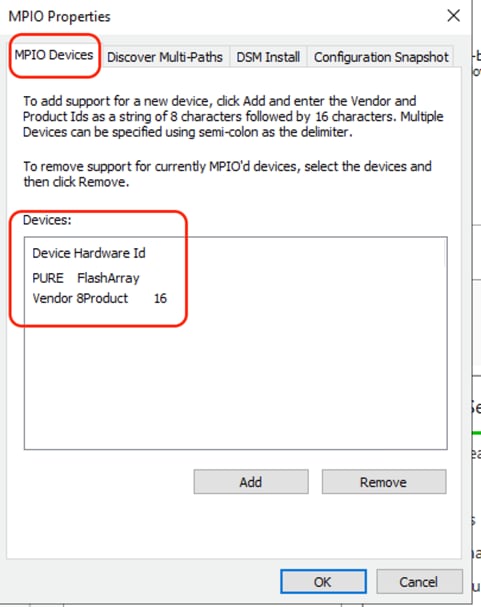
Windows Server Disk Configuration
To configure ReFS File System on the Disk Volumes across each of the configurations, follow these steps:
1. Go to Server Manager > File and Storage Services.
2. Navigate to Volumes > Disks and select the volume with Partition type as Unknown.
3. Create New Volume, Click Next until you reach Select File System settings window.
4. Select File System type is ReFS and Allocation Unit Size as 64K, shown below.
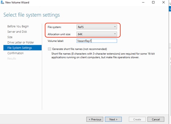
5. Click Next and then click Finish Creating ReFS File System.
The key characteristics for the disk configuration for each of the different deployments for FlashStack Protection are described below:
● Cisco UCS S3260 Storage Server: This configuration utilizes two Rear SSD drives for boot and installation of the Veeam Backup and Replication Server and 56 top load drives on S3260 Storage Server. RAID1 is created across the Rear Boot drive. As detailed in the previous sections, two RAID60 volumes are created across 28 disks each. This allows to utilize the 4G cache on each chip of the dual-chip RAID controller and provides maximum backup throughout across a Veeam Scale-Out Backup Repository. File and Storage Services volumes utilized in this deployment are detailed below.
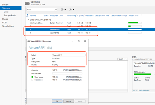
● Cisco UCS C240 All Flash Rack Server: The present configuration utilizes 24 front load SSDs with two Rear SSD drives for boot and installation of the Veeam Backup and Replication Server. As detailed in the previous sections, a single RAID6 volume is created across 24 SSDs and RAID1 across the Rear SSDs. File and Storage Services volumes utilized in this deployment are detailed below.
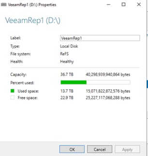
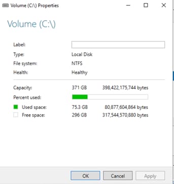
● Cisco UCS C220 Rack Server with Pure Storage FlashArray//C: In this configuration, Cisco UCS C220 Rack Server provides compute and Disk Volumes are assigned on FlashArray//C connected over Fibre Channel. File and Storage Services volumes utilized in this deployment is detailed below.
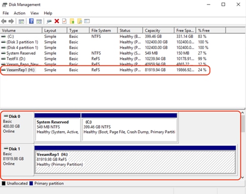
![]() The ReFS volumes provide significantly faster synthetic full backup creation and transformation performance, as well as reduce storage requirements and improve reliability due to Block Cloning. Even more importantly, this functionality improves availability of backup storage by significantly reducing its load — which results in improved backup and restore performance and enables customers to do much more with virtual labs running on the backup storage.
The ReFS volumes provide significantly faster synthetic full backup creation and transformation performance, as well as reduce storage requirements and improve reliability due to Block Cloning. Even more importantly, this functionality improves availability of backup storage by significantly reducing its load — which results in improved backup and restore performance and enables customers to do much more with virtual labs running on the backup storage.
Install and Configure Veeam Backup and Replication 11
This section highlights the key configuration to ensure the proper installation of Veeam on the following:
● Cisco UCS S3260 storage server
● Cisco UCS C240 All Flash Rack Server
● Cisco UCS C220 Rack Server with FlashArray//C
For detailed information about installing Veeam Backup and Replication 11, refer to Veeam Installation.
During Veeam 11 installation on Cisco UCS S3260 storage server, ensure that the Write Cache and Veeam Guest Catalog directories are configured on C: drive or the boot drive. The Rear Boot drives are configured with SSDs which provide lower latencies for Veeam cache.
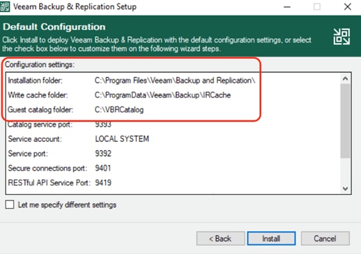
To achieve maximum performance on Cisco UCS S3260 Storage server, create a Veeam Scale-Out Repository across two 28 disk RAID60 disk volumes.
The ‘maximum concurrent task’ under the Veeam Backup Repository configuration should be unchecked and the ‘Use per-VM backup files’ is checked.
In all the three deployments, the Veeam Backup Proxy resides on the same compute server as Veeam Console. The ‘Max concurrent Task’ in Veeam Backup Proxy should be equal to (total physical CPU cores available -2). The present configuration has dual socket CPUs with 16 physical cores each. The ‘max concurrent task’ is set to 30. The maximum number of concurrent tasks depends on the number of CPU cores available in the Backup Repository. For more information, refer to: Veeam Limitation of Concurrent Tasks
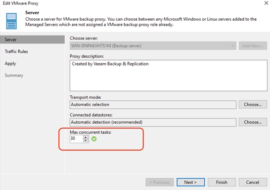
In all the three deployments, the Veeam Backup Proxy resides on the same compute server as Veeam Console. To enable Veeam backup and restore from Pure storage snapshots, the Veeam Backup Proxy server should have access to Pure Storage FlashArray//X (part of FlashStack as backup source) and vHBA on the server should be zoned on the Cisco MDS switch. The Veeam Backup Proxy must be registered with a WWN on the Pure Storage array. The configuration on Pure Storage FlashArray//X is detailed below:
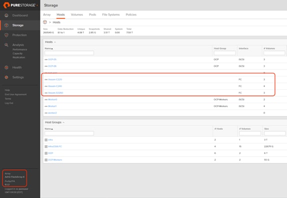
The volumes on FlashStack with Pure Storage FlashArray//X should be visible on each of the Veeam Backup Proxy server. This is detailed on the Windows Disk Management Tool.
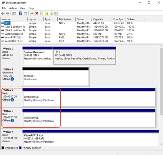
Pure Storage Plug-In for Veeam 11
Veeam Universal Storage API Framework offers built-in integrations with storage systems to help decrease impact on the production environment and significantly improve RPOs. Pure Storage is part of the Veeam Storage Integration Framework. Performance on the primary VMware estate when it comes to creating VMware snapshots, offloading this process to the storage array to then taking the backup from the storage. For more information refer to: Snapshot Integration for Pure Storage now available for Veeam Backup & Replication
![]() The details of this section are common to Veeam Server Deployments across Cisco UCS S3260 storage server, Cisco USC C240 All Flash Rack Server, and Cisco UCS C220 Rack server with Fibre Channel connectivity to the Pure Storage FlashArray//C.
The details of this section are common to Veeam Server Deployments across Cisco UCS S3260 storage server, Cisco USC C240 All Flash Rack Server, and Cisco UCS C220 Rack server with Fibre Channel connectivity to the Pure Storage FlashArray//C.
The key steps to install the Pure Storage plug-in for Veeam 11 are as follows:
1. Download the latest Pure Storage Plug-in for Veeam, version 1.2.45
2. Run the Pure Storage plug-in installer.
3. Click Next and accept the default settings.
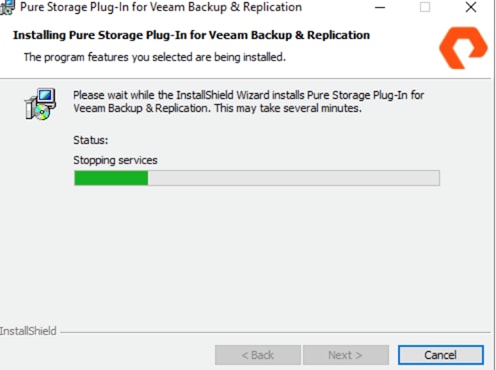
4. Click Finish to complete the plug-in installation.
Configure Pure Storage Integration with Veeam
![]() The details of this section are common to Veeam Server Deployments across Cisco UCS S3260 storage server, Cisco US C240 All Flash Rack Server, and Cisco UCS C220 Rack server with Fibre Channel connectivity to Pure Storage FlashArray//C.
The details of this section are common to Veeam Server Deployments across Cisco UCS S3260 storage server, Cisco US C240 All Flash Rack Server, and Cisco UCS C220 Rack server with Fibre Channel connectivity to Pure Storage FlashArray//C.
To allow storage integration of Pure Storage FlashArray//X (part of FlashStack environment) with Veeam Backup Server, follow these steps:
1. Download the latest Pure Storage Plug-in for Veeam version 1.2.45.
2. In the Veeam console, go to Storage Infrastructure and click Add Storage. Select Pure Storage from the ‘Add Storage’ popup window.
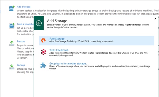
3. Enter the Management IP of Pure Storage FlashArray//X (part of FlashStack environment). Select Block or File Storage for VMware vSphere. Click Next.
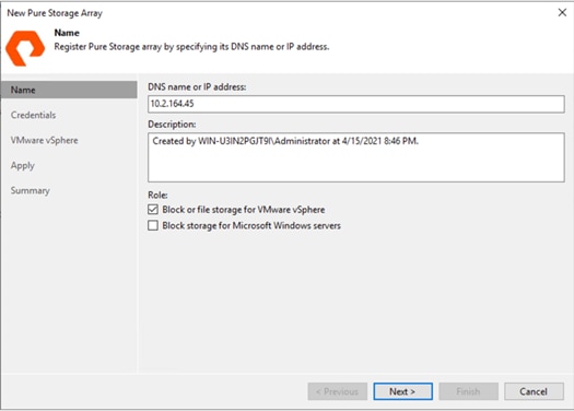
4. Add Credentials of Pure FlashArray//X management.
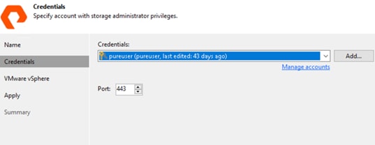
5. For Protocols select Fibre Channel and iSCSI. Leave the Volumes and Backup proxies to default. Click Apply.
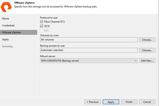
6. Confirm addition of Pure Storage FlashArray//X and click Finish.
7. Confirm the LUNs on FlashArray//X are identified for backup through storage snapshots.
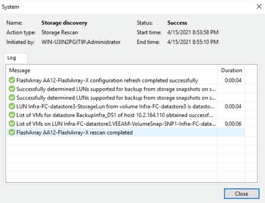
Solution Testing and Validation
All validation testing was conducted on-site within the Cisco labs in RTP, North Carolina.
This section describes the test executed to validate the FlashStack Data Protection with Veeam on the following platforms:
● Cisco UCS S3260 Storage Server
● Cisco UCS C240 All Flash Rack Server
● Cisco UCS C220 Rack Server with Pure Storage FlashArray//C
This section details the Backup and Restore validation of Virtual Infrastructure on FlashStack environment.
To backup the virtual machine on the FlashStack environment, follow these steps:
1. Verify Pure Storage FlashArray//X is configured through Veeam Storage Integration.
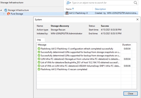
2. Identify the VMs on FlashStack environment, click Add.
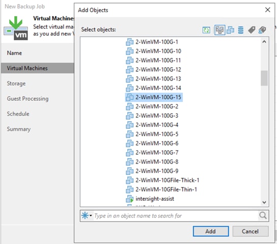
3. Select the Veeam Backup Repository configured on the backup target and ensure ‘Enable Backup from Storage Snapshots’ is selected. This is selected by default.
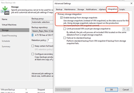
4. Click Next and check the option ‘Run the job when I click Finish’ and complete the backup job creation.
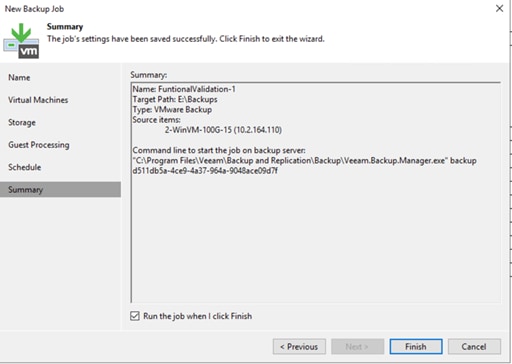
5. When the job is started, ensure ‘Backup from Storage Snapshot’ is detailed in the Status window.
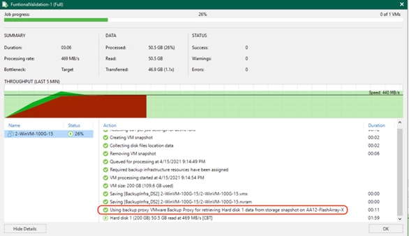
6. Confirm the successful completion of backup job of VMs on the FlashStack infrastructure.
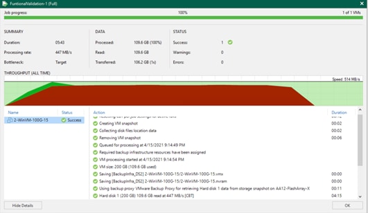
To validate entire VM restore of a backup to FlashStack environment, follow these steps:
1. From the Veeam Management console, click Restore to VMware vSphere and click Restore from Backup.
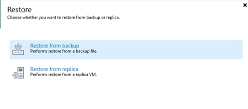
2. Click Virtual Machines and click Add VM and select From backup.
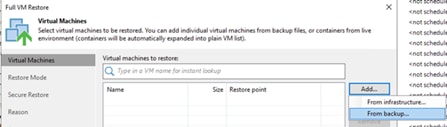
3. Select the VM backed up in the previous section.
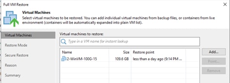
4. Select Restore to a new location, or with different settings and click Next.
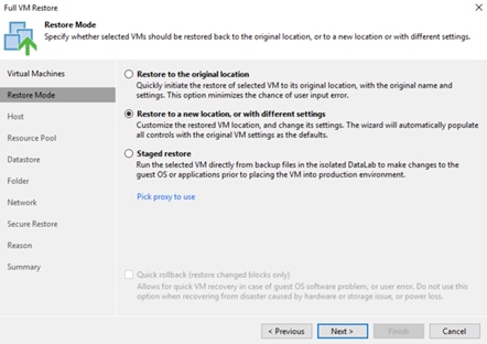
5. Click Next and edit the Disk Type Settings to Thick (eager zeroed). The VM backed up was created with Thin Disk. Restore through SAN Mode can be achieved by the following:
● Either a VM created on Thick Disk, or
● Disk Type of restore VM is selected as Thick Disk
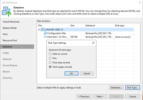
6. Click Next and then click Finish the restore job creation.
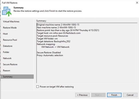
7. Monitor the progress of restore job to FlashStack environment and ensure the restore is through SAN Mode.
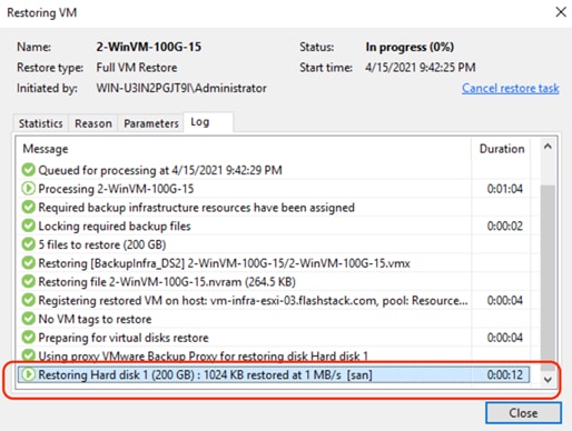
8. Verify the successful restore of VM from backup to FlashStack environment.
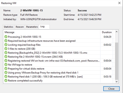
This section discusses the key performance metrics that were captured for backup and restore of virtual infrastructure on FlashStack environment with Veeam v11. The setup was provisioned with three backup targets as detailed below.
Cisco UCS S3260 storage server with the Veeam Server, Backup Proxy and Backup Repository are on the same server. The two Veeam Backup Repository options tested are:
● Backup on a simple Veeam Storage Repository with RAID 60 disk volume created with 56 top load NL-SAS 7.2 RPM drives
● Backup on Veeam Scale-Out Backup Repository with two extents configured with RAID 60 disk volume each. These were created with 28 top load NL-SAS 7.2 RPM drives
Cisco UCS C240 All Flash Rack Server with Veeam Server, Backup Proxy and Backup Repository are on same server.
Backup on Veeam Backup Repository with RAID6 disk volume created with 24 x 1.9 TB Enterprise Value 6G ATA SSD.
Cisco UCS C220 Rack Server with Pure Storage FlashArray//C60 345TB as Veeam Backup Repository.
All the restores were on FlashStack environment with Pure Storage FlashArray//X R2. Entire VM restore was executed from Backups.
Figure 51. Performance Test Setup Details
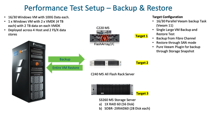
Some of the key features of performance test are as follows:
● Windows VMs created on FlashStack environment were provisioned with 100G Data. A Total of 30 such VMs were created on the FlashStack environment
● To test backup and restore of a single large VM, test bed was provisioned with 1x Windows VM with 2 x VMDK of 4 TB each with 2 TB of data in each of the VMDK
● Disk tool was utilized to create VM Data which was not compressible through Veeam
● All the backups were executed through Direct SAN mode over Fibre Channel network.
● Pure Storage plug-in for Veeam was installed on each of the Veeam Server and the Pure Storage FlashArray//X was added into the Veeam Storage Infrastructure. This allowed backup of VMs from storage snapshots
● Restore through San Mode was utilized
● Efficiency (compression and deduplication) of backups was measured across all the three backup infrastructure platforms
The performance tests were executed for 16 and 30 parallel Veeam tasks for 16 and 30 VMs with 100G incompressible data in each of the VM.
Backup throughput results across the three storage targets are shown below:
Figure 52. Veeam parallel Backup performance
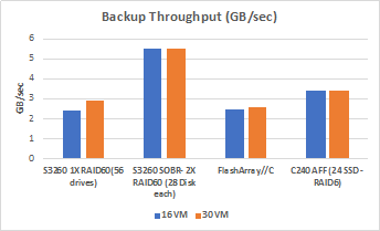
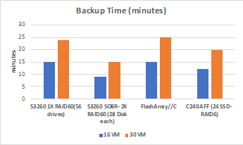
The key metrics of the results are as follows:
● Veeam processing rate was captured as the average backup throughput in GB/sec
● Total backup time is the time taken to complete parallel backup of 16 VMs and 30 VMs provisioned on the FlashStack environment
The backups from Veeam were restored to the FlashStack environment. The test was executed for the ‘entire VM restore’ of 16 and 30 VMs in parallel from backups created on each of the backup targets.
The entire VM restore results are shown below:
Figure 53. Veeam Entire VM Restore Performance
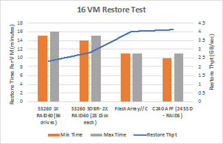
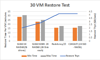
The key metrics of the results are as follows:
● Restore throughput was captured from Pure Storage FlashArray//X dashboard
● Minimum backup time is the time for the first VM to complete restoration in 16 and 30 VM parallel restore job
● Maximum backup time is the time for the last VM to complete restoration in 16 and 30 VM parallel restore job
● VMs were created with incompressible data, in the final results:
◦ Data efficiency for Veeam Backup Repositories on Cisco UCS S3260 Storage Server and C240 All Flash Rack Server was 1x
◦ Data efficiency displayed on FlashArray//C dashboard for Veeam Backup Repository Volumes was 6x to 7x
Single Large VM Backup and Restore Test
The performance tests were executed to determine the backup time and backup throughput for a single large Windows VM with 2 x VMDK of 4 TB each with 2 TB. Incompressible data was generated through Disk Tool.
Backup throughput results across the three storage targets are shown below:
Figure 54. Single Large VM Backup and Restore Performance
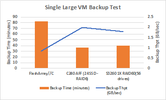
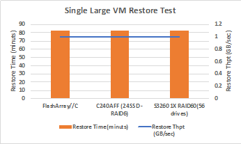
Failure and Resiliency Testing
Failure testing was completed on the entire backup infrastructure. All failover and redundancy tests were conducted while at least one active Veeam backup Job was running. The key test involved are as follows:
● Failure of active Cisco Fabric Interconnect
● Failure of one of the Cisco MDS Fibre Channel Switch
● Failure of one of the Cisco Nexus Switch
● Failure of one of the Pure Storage FlashArray//C controller
To minimize the impact of active path, customers are recommended to use the Fibre Channel Adapter policy as recommended in this guide. The key results of the failure test are as follows:
● Veeam backup throughput reduction during failures was minimal. Veeam displayed reduced backup throughout for around 5-10 sec during failure of one of the Pure Storage FlashArray//C Controller or Cisco MDS switch.
● FlashArray//C displayed near zero IO for around 10-12 seconds during failure of one of FlashArray//C controllers or Cisco MDS switches.
The BOM below lists the major components validated, but it is not intended to be a comprehensive list.
| Line Number |
Part Number |
Description |
Qty |
| 1.0 |
UCSS-S3260 |
Cisco UCS S3260 Storage Server Base Chassis |
1 |
| 1.0.1 |
CON-OSP-UCSS3260 |
SNTC 24X7X4OS, Cisco UCS S3260 Storage Server Base Chassis |
1 |
| 1.1 |
UCSC-PSU1-1050W |
Cisco UCS 1050W AC Power Supply for Rack Server |
4 |
| 1.2 |
CAB-C13-C14-3M-IN |
Power Cord Jumper, C13-C14 Connectors, 3 Meter Length, India |
4 |
| 1.3 |
CIMC-LATEST |
IMC SW (Recommended) latest release for C-Series Servers. |
1 |
| 1.4 |
N20-BKVM |
KVM local IO cable for UCS servers console port |
1 |
| 1.5 |
N20-BBLKD-7MM |
Cisco UCS 7MM SSD Blank Filler |
2 |
| 1.6 |
UCSC-C3X60-BLKP |
Cisco UCS C3X60 Server Node blanking plate |
1 |
| 1.7 |
UCSC-C3X60-SBLKP |
Cisco UCS C3x60 SIOC blanking plate |
1 |
| 1.8 |
UCSC-C3X60-RAIL |
Cisco UCS C3X60 Rack Rails Kit |
1 |
| 1.9 |
UCSS-S3260-BBEZEL |
Cisco UCS S3260 Bezel |
1 |
| 1.10 |
UCS-S3260-M5SRB |
Cisco UCS S3260 M5 Server Node for Intel Scalable CPUs |
1 |
| 1.11 |
UCS-CPU-I6226R |
Intel 6226R 2.9GHz/150W 16C/22MB DDR4 2933MHz |
2 |
| 1.12 |
UCS-MR-X32G2RT-H |
32GB DDR4-2933-MHz RDIMM/2Rx4/1.2v |
12 |
| 1.13 |
UCS-S3260-DRAID |
Cisco UCS S3260 Dual Raid based on LSI 3316 |
1 |
| 1.14 |
UCS-S3260-M5HS |
Cisco UCS S3260 M5 Server Node HeatSink |
2 |
| 1.15 |
UCS-S3260-PCISIOC |
Cisco UCS S3260 PCIe SIOC |
1 |
| 1.16 |
UCSC-PCIE-C25Q-04 |
Cisco UCS VIC 1455 Quad Port 10/25G SFP28 CNA PCIE |
1 |
| 1.17 |
UCSC-LP-C25-1485 |
Low profile bracket for VIC |
1 |
| 1.18 |
UCS-S3260-56HD8A |
Cisco UCS S3260 4row of drives 56x8TB NL-SAS 7200RPM (Total 448TB) |
1 |
| 1.19 |
UCS-S3260-HD8TA |
8 TB 12G SAS 7.2K RPM LFF HDD (4K) |
56 |
| 1.20 |
UCS-S3260-G3SD48 |
Cisco UCS S3260 480G Boot SSD (Micron 6G SATA) |
2 |
| 2.0 |
UCSC-C220-M5SX |
Cisco UCS C220 M5 SFF 10 HD w/o CPU, mem, HD, PCIe, PSU |
1 |
| 2.0.1 |
CON-OSP-C220M5SX |
SNTC 24X7X4OS UCS C220 M5 SFF 10 HD w/o CPU, mem, HD, PCIe, |
1 |
| 2.1 |
UCS-MR-X32G2RT-H |
32GB DDR4-2933-MHz RDIMM/2Rx4/1.2v |
12 |
| 2.2 |
UCSC-MLOM-C25Q-04 |
Cisco UCS VIC 1457 Quad Port 10/25G SFP28 CNA MLOM |
1 |
| 2.3 |
UCSC-PSU1-770W |
Cisco UCS 770W AC Power Supply for Rack Server |
2 |
| 2.4 |
CAB-C13-C14-AC |
Power cord, C13 to C14 (recessed receptacle), 10A |
2 |
| 2.5 |
UCSC-RAILB-M4 |
Ball Bearing Rail Kit for C220 & C240 M4 & M5 rack servers |
1 |
| 2.6 |
CIMC-LATEST |
IMC SW (Recommended) latest release for C-Series Servers. |
1 |
| 2.7 |
UCS-SID-INFR-DTP |
Data Protection Platform |
1 |
| 2.8 |
UCS-SID-WKL-DP |
Data Protection (Commvault, Veeam only) |
1 |
| 2.9 |
UCSC-BBLKD-S2 |
Cisco UCS C-Series M5 SFF drive blanking panel |
10 |
| 2.10 |
UCSC-HS-C220M5 |
Heat sink for UCS C220 M5 rack servers 150W CPUs & below |
2 |
| 2.11 |
UCSC-SATAIN-220M5 |
Cisco C220 M5 (8-drive) SATA Interposer board |
1 |
| 2.12 |
UCS-CPU-I6226R |
Intel 6226R 2.9GHz/150W 16C/22MB DDR4 2933MHz |
2 |
| 3.0 |
UCSC-C240-M5S |
Cisco UCS C240 M5 8 SFF + 2 rear drives w/o CPU,mem,HD,PCIe,PS |
1 |
| 3.0.1 |
CON-OSP-CC240M5S |
SNTC 24X7X4OS UCS C240 M5 8 SFF + 2 rear drives w/o CPU,mem, |
1 |
| 3.1 |
UCS-MR-X32G2RT-H |
32GB DDR4-2933-MHz RDIMM/2Rx4/1.2v |
12 |
| 3.2 |
UCSC-PCI-1B-240M5 |
Riser 1B incl 3 PCIe slots (x8, x8, x8); all slots from CPU1 |
1 |
| 3.3 |
UCSC-MLOM-C25Q-04 |
Cisco UCS VIC 1457 Quad Port 10/25G SFP28 CNA MLOM |
1 |
| 3.4 |
UCSC-PSU1-1050W |
Cisco UCS 1050W AC Power Supply for Rack Server |
2 |
| 3.5 |
CAB-C13-CBN |
Cabinet Jumper Power Cord, 250 VAC 10A, C14-C13 Connectors |
2 |
| 3.6 |
UCSC-RAILB-M4 |
Ball Bearing Rail Kit for C220 & C240 M4 & M5 rack servers |
1 |
| 3.7 |
CIMC-LATEST |
IMC SW (Recommended) latest release for C-Series Servers. |
1 |
| 3.8 |
UCS-SID-INFR-DTP |
Data Protection Platform |
1 |
| 3.9 |
UCS-SID-WKL-DP |
Data Protection (Commvault, Veeam only) |
1 |
| 3.10 |
UCSC-HS-C240M5 |
Heat sink for UCS C240 M5 rack servers 150W CPUs & below |
2 |
| 3.11 |
UCSC-PCIF-240M5 |
Cisco UCS C240 M5 PCIe Riser Blanking Panel |
1 |
| 3.12 |
UCSC-BBLKD-S2 |
Cisco UCS C-Series M5 SFF drive blanking panel |
7 |
| 3.13 |
CBL-SC-MR12GM52 |
Super Cap cable for UCSC-RAID-M5 on C240 M5 Servers |
1 |
| 3.14 |
UCSC-RSAS-C240M5 |
Cisco UCS C240 Rear UCSC-RAID-M5 SAS cbl(1)kit incl,bkplnforSFF&LFF |
1 |
| 3.15 |
UCSC-SCAP-M5 |
Super Cap for UCSC-RAID-M5, UCSC-MRAID1GB-KIT |
1 |
| 3.16 |
UCS-CPU-I6226R |
Intel 6226R 2.9GHz/150W 16C/22MB DDR4 2933MHz |
2 |
| 3.17 |
UCSC-RAID-M5 |
Cisco 12G Modular RAID controller with 2GB cache |
1 |
| 3.18 |
UCS-SD19TM1X-EV |
1.9TB 2.5 inch Enterprise Value 6G SATA SSD |
1 |
| 3.19 |
UCS-SD480GM3X-EP |
480GB 2.5in Enterprise Performance 6GSATA SSD(3X endurance) |
2 |
| 4.0 |
UCS-FI-6454-U |
Cisco UCS Fabric Interconnect 6454 |
2 |
| 4.0.1 |
CON-OSP-SFI6454U |
SNTC-24X7X4OS UCS Fabric Interconnect 6454 |
2 |
| 4.1 |
N10-MGT017 |
Cisco UCS Manager v4.1 |
2 |
| 4.2 |
UCS-PSU-6332-AC |
Cisco UCS 6332/ 6454 Power Supply/100-240VAC |
4 |
| 4.3 |
CAB-C13-C14-AC |
Power cord, C13 to C14 (recessed receptacle), 10A |
4 |
| 4.4 |
UCS-ACC-6332 |
Cisco UCS 6332/ 6454 Chassis Accessory Kit |
2 |
| 4.5 |
UCS-FAN-6332 |
Cisco UCS 6332/ 6454 Fan Module |
8 |
| FA-C60-FC-345TB-247/98 |
Pure Storage FlashArray C60-FC-345TB-247/98 |
1 |
|
| 5.1 |
FA-XR2-32G-FC-SFP-SR |
32G FC SFP, SW for XR2 |
8 |
Anil Dhiman, Technical Marketing Engineer, UCS Data Center Solutions Engineering, Cisco Systems, Inc.
Anil specializes in Cisco UCS Data Center technologies, with a key focus on Cisco’s portfolio of hyperconverged infrastructure, data protection solutions, and performance engineering of large-scale enterprise applications. Over the last 10 years with Cisco, Anil has authored several Cisco Validated Designs for Enterprise Solutions on Cisco Data Center Technologies.
Sreenivasa Edula, Technical Marketing Engineer, UCS Data Center Solutions Engineering, Cisco Systems, Inc.
Sreeni is a Technical Marketing Engineer in the Cisco UCS Data Center Solutions Engineering team focusing on converged and hyperconverged infrastructure solutions. Previously, he worked as a Solutions Architect at EMC Corporation. Sreeni has experience in Information Systems with expertise across the Cisco Data Center technology portfolio, including DC architecture design, virtualization, compute, network, storage, and cloud computing.
For their support and contribution to the design, validation, and creation of this Cisco Validated Design, we would like to acknowledge the following for their contribution and expertise that resulted in developing this document:
● Roy Child, Sr Solutions Architect, Data Protection, Pure Storage Inc.
● David Huskisson, Senior Solutions Manager, Pure Storage Inc.
● Craig Waters, Technical Director, Cisco Solutions, Pure Storage Inc.
● Mark Polin, Cisco/Pure Storage Alliance Solutions Architect, Veeam Software
This section provides links to additional information for each partner’s solution component of this document.
Cisco UCS C-Series Rack Server
Cisco UCS S-Series Storage Server
● https://www.cisco.com/c/dam/en/us/products/collateral/servers-unified-computing/ucs-s-series-storage-servers/s3260-specsheet.pdf
Cisco UCS Manager Configuration Guides
Cisco UCS Virtual Interface Cards
Cisco Nexus Switching References
● https://www.cisco.com/c/en/us/products/switches/nexus-93180yc-fx-switch/index.html
Cisco MDS 9000 Service Switch References
● http://www.cisco.com/c/en/us/products/storage-networking/product-listing.html
● https://www.cisco.com/c/en/us/products/collateral/storage-networking/mds-9132T 32-Gb-16g-multilayer-fabric-switch/datasheet-c78-731523.html
Veeam Availability Suite References
● https://helpcenter.veeam.com/docs/backup/qsg_vsphere/setup.html?ver=110
Pure Storage Reference Documents
● https://www.purestorage.com/products/nvme/high-capacity/flasharray-c/data-sheet.html
● https://www.purestorage.com/products/evergreen-subscriptions.html
● https://support.purestorage.com/Solutions/Microsoft_Platform_Guide/Multipath-IO_and_Storage_Settings/Configuring_Multipath-IO
For comments and suggestions about this guide and related guides, join the discussion on Cisco Community at https://cs.co/en-cvds.