FlexPod Datacenter with Citrix XenDesktop/ XenApp 7.7 and VMware vSphere 6.0 for 5000 Seats
Available Languages

FlexPod Datacenter with Citrix XenDesktop/ XenApp 7.7 and VMware vSphere 6.0 for 5000 Seats
Cisco Validated Design for a 5,000 Seat Virtual Desktop Infrastructure using Citrix XenDesktop/XenApp 7.7. Built on Cisco UCS and Cisco Nexus 9000 Series with NetApp AFF 8080EX and the VMware vSphere ESXi 6.0 Update 1 Hypervisor Platform
Last Updated: May 15, 2018

About Cisco Validated Designs
The CVD program consists of systems and solutions designed, tested, and documented to facilitate faster, more reliable, and more predictable customer deployments. For more information visit:
http://www.cisco.com/go/designzone.
ALL DESIGNS, SPECIFICATIONS, STATEMENTS, INFORMATION, AND RECOMMENDATIONS (COLLECTIVELY, "DESIGNS") IN THIS MANUAL ARE PRESENTED "AS IS," WITH ALL FAULTS. CISCO AND ITS SUPPLIERS DISCLAIM ALL WARRANTIES, INCLUDING, WITHOUT LIMITATION, THE WARRANTY OF MERCHANTABILITY, FITNESS FOR A PARTICULAR PURPOSE AND NONINFRINGEMENT OR ARISING FROM A COURSE OF DEALING, USAGE, OR TRADE PRACTICE. IN NO EVENT SHALL CISCO OR ITS SUPPLIERS BE LIABLE FOR ANY INDIRECT, SPECIAL, CONSEQUENTIAL, OR INCIDENTAL DAMAGES, INCLUDING, WITHOUT LIMITATION, LOST PROFITS OR LOSS OR DAMAGE TO DATA ARISING OUT OF THE USE OR INABILITY TO USE THE DESIGNS, EVEN IF CISCO OR ITS SUPPLIERS HAVE BEEN ADVISED OF THE POSSIBILITY OF SUCH DAMAGES.
THE DESIGNS ARE SUBJECT TO CHANGE WITHOUT NOTICE. USERS ARE SOLELY RESPONSIBLE FOR THEIR APPLICATION OF THE DESIGNS. THE DESIGNS DO NOT CONSTITUTE THE TECHNICAL OR OTHER PROFESSIONAL ADVICE OF CISCO, ITS SUPPLIERS OR PARTNERS. USERS SHOULD CONSULT THEIR OWN TECHNICAL ADVISORS BEFORE IMPLEMENTING THE DESIGNS. RESULTS MAY VARY DEPENDING ON FACTORS NOT TESTED BY CISCO.
CCDE, CCENT, Cisco Eos, Cisco Lumin, Cisco Nexus, Cisco StadiumVision, Cisco TelePresence, Cisco WebEx, the Cisco logo, DCE, and Welcome to the Human Network are trademarks; Changing the Way We Work, Live, Play, and Learn and Cisco Store are service marks; and Access Registrar, Aironet, AsyncOS, Bringing the Meeting To You, Catalyst, CCDA, CCDP, CCIE, CCIP, CCNA, CCNP, CCSP, CCVP, Cisco, the Cisco Certified Internetwork Expert logo, Cisco IOS, Cisco Press, Cisco Systems, Cisco Systems Capital, the Cisco Systems logo, Cisco Unity, Collaboration Without Limitation, EtherFast, EtherSwitch, Event Center, Fast Step, Follow Me Browsing, FormShare, GigaDrive, HomeLink, Internet Quotient, IOS, iPhone, iQuick Study, IronPort, the IronPort logo, LightStream, Linksys, MediaTone, MeetingPlace, MeetingPlace Chime Sound, MGX, Networkers, Networking Academy, Network Registrar, PCNow, PIX, PowerPanels, ProConnect, ScriptShare, SenderBase, SMARTnet, Spectrum Expert, StackWise, The Fastest Way to Increase Your Internet Quotient, TransPath, WebEx, and the WebEx logo are registered trademarks of Cisco Systems, Inc. and/or its affiliates in the United States and certain other countries.
All other trademarks mentioned in this document or website are the property of their respective owners. The use of the word partner does not imply a partnership relationship between Cisco and any other company. (0809R)
© 2016 Cisco Systems, Inc. All rights reserved.
Table of Contents
FlexPod Data Center with Cisco UCS
Benefits of Cisco Unified Computing System
Benefits of Cisco Nexus Physical and Virtual Switching
Benefits of NetApp Cluster Data ONTAP Storage Controllers
Benefits of VMware vSphere ESXi 6.0
Benefits of Citrix XenApp and XenDesktop 7.7
Cisco Unified Computing System
Cisco Unified Computing System Components
Cisco UCS B200 M4 Blade Server
Cisco UCS VIC1340 Converged Network Adapter
Cisco Nexus 1000V Distributed Virtual Switch
Important Differentiators for the Cisco Nexus 1000V for VMware vSphere
Citrix XenApp and XenDesktop 7.7
Improved Database Flow and Configuration
Multiple Notifications before Machine Updates or Scheduled Restarts
API Support for Managing Session Roaming
API Support for Provisioning VMs from Hypervisor Templates
Support for New and Additional Platforms
Citrix Provisioning Services 7.7
NetApp AFF8080EX-A Used in Testing
Cisco Desktop Virtualization Solutions: Data Center
Cisco Desktop Virtualization Focus
Understanding Applications and Data
Project Planning and Solution Sizing Sample Questions
Desktop Virtualization Design Fundamentals
Example XenDesktop Deployments
Designing a XenDesktop Environment for a Mixed Workload
High-Level Architecture Design
NetApp Architecture Design Best Practice Guidelines
Storage Architecture Design Layout
Network Port Settings (8.3 or Later)
Network Port Broadcast Domains
Storage Efficiency And Space Management
Deployment Hardware and Software
Cisco Unified Computing System Configuration
Configure Fabric Interconnect at Console
Base Cisco UCS System Configuration
Enable Server Uplink and Storage Ports
Set Jumbo Frames in Cisco UCS Fabric
Create Local Disk Configuration Policy (Optional)
Create Network Control Policy for Cisco Discovery Protocol
Create Server Pool Qualification Policy (Optional)
Create vNIC/vHBA Placement Policy for Virtual Machine Infrastructure Hosts
Configure Update Default Maintenance Policy
Create Service Profile Templates
Configuration of AFF8080EX-A with Clustered Data ONTAP
Clustered Data ONTAP 8.3 ADP and Active–Active Configuration
Configuring Boot from iSCSI on NetApp AFF8080EX-A
Storage Considerations for PVS vDisks
Create Storage Volumes for PVS vDisks
NetApp Storage Configuration for CIFS Shares
Create User Home Directory Shares in Clustered Data ONTAP
Configuring Boot from SAN Overview
Configuring Boot from iSCSI on NetApp AFF8080
Clustered Data ONTAP iSCSI Configuration
iSCSI SAN Configuration on Cisco UCS Manager
Installing and Configuring VMware ESXi 6.0
Download Cisco Custom Image for ESXi 6 Update1
Set Up VMware ESXi Installation
Set Up Management Networking for ESXi Hosts
Download VMware vSphere Client and vSphere Remote CLI
Log in to VMware ESXi Hosts by using VMware vSphere Client
Download Updated Cisco VIC eNIC Drivers
Load Updated Cisco VIC eNIC Drivers
Set Up VMkernel Ports and Virtual Switch
Install and Configure vCenter 6.0
FlexPod VMware vCenter Appliance
Install the Client Integration Plug-in
ESXi Dump Collector Setup for iSCSI-Booted Hosts
Installing and configuring NetApp Virtual Storage Console (VSC)
FlexVol Volumes in Clustered Data ONTAP
FlexPod Cisco Virtual Switch Update Manager and Nexus 1000V
Installing Cisco Virtual Switch Update Manager
Install Cisco Virtual Switch Update Manager
Install Cisco Nexus 1000V using Cisco VSUM
Perform Base Configuration of the Primary VSM
Add VMware ESXi Hosts to Cisco Nexus 1000V
Migrate ESXi Host Redundant Network Ports to Cisco Nexus 1000V
Building the Virtual Machines and Environment
Software Infrastructure Configuration
Installing and Configuring XenDesktop and XenApp
Install XenDesktop Delivery Controller, Citrix Licensing and StoreFront
Additional XenDesktop Controller Configuration
Add the Second Delivery Controller to the XenDesktop Site
Create Host Connections with Citrix Studio
Installing and Configuring Citrix Provisioning Server 7.7
Install Additional PVS Servers
Install XenDesktop Virtual Desktop Agents
Install the Citrix Provisioning Server Target Device Software
Create Citrix Provisioning Server vDisks
Provision Virtual Desktop Machines
Configure User Profile Manager Share on NetApp AFF8080
Citrix XenDesktop Policies and Profile Management
Configure Citrix XenDesktop Policies
Configuring User Profile Management
Install and Configure NVIDIA M6 Card
Physical Install of M6 Card into B200 M4 Server
Install the NVIDIA VMware VIB Driver
Install the GPU Drivers inside your Windows VM
Install and Configure NVIDIA Grid License Server
Installing Cisco UCS Performance Manager
Configure the Control Center Host Mode
Enabling Access to Browser Interfaces
Deploy Cisco UCS Performance Manager
Setting up Cisco UCS Performance Manager
Add Nexus 9000 Series Switches
Cisco UCS Performance Manager Sample Test Data
Cisco UCS Test Configuration for Single Blade Scalability
Cisco UCS Configuration for Cluster Testing
Cisco UCS Configuration for Full Scale Testing
Testing Methodology and Success Criteria
Server-Side Response Time Measurements
Single-Server Recommended Maximum Workload
Single-Server Recommended Maximum Workload Testing
Single-Server Recommended Maximum Workload for RDS with 240 Users
Single-Server Recommended Maximum Workload for VDI Non-Persistent with 195 Users
Single-Server Recommended Maximum Workload for VDI Persistent with 195 Users
Cluster Workload Testing with 2600 RDS Users
Key NetApp AFF8080EX Performance Metrics During RDS Cluster Workload Testing
Key Infrastructure VM Server Performance Metrics During RDS Cluster Workload Testing
Cluster Workload Testing with 1200 Non-Persistent Desktop Users
Key NetApp AFF8080EX-A Performance Metrics during VDI Non-Persistent Cluster Workload Testing
Key Infrastructure VM Server Performance Metrics during VDI Non-Persistent Cluster Workload Testing
Cluster Workload Testing with 1200 Persistent Desktop Users
Key NetApp AFF8080EX Performance Metrics during VDI Persistent Cluster Workload Testing
Key Infrastructure VM Server Performance Metrics during VDI Persistent Cluster Testing
Full Scale Mixed Workload Testing with 5000 Users
Key NetApp AFF8080EX Performance Metrics during Full Scale Testing
Key Infrastructure VM Server Performance Metrics during Full Scale Testing
Scalability Considerations and Guidelines
NetApp FAS Storage Guidelines for Mixed Desktop Virtualization Workloads
Scalability of Citrix XenDesktop 7.7 Configuration
Appendix A Cisco Nexus 9372 Configuration
Appendix B NetApp AFF8080 Monitoring with PowerShell Scripts
Creating User Home Directory Folders with a Powershell Script
Appendix C Additional Test Results
Login VSI Test Report for Full Scale Mixed Testing
This document provides a Reference Architecture for a virtual desktop and application design using Citrix XenApp/XenDesktop 7.7 built on Cisco UCS with a NetApp AFF 8080 EX and the VMware vSphere ESXi 6.0 Update-1 hypervisor platform.
The landscape of desktop and application virtualization is changing constantly. New, high performance Cisco UCS Blade Servers and Cisco UCS unified fabric combined as part of the FlexPod Proven Infrastructure with the latest generation NetApp AFF storage result in a more compact, more powerful, more reliable and more efficient platform.
In addition, the advances in the Citrix XenApp/XenDesktop 7.7 system, which now incorporates both traditional hosted virtual Windows 7, Windows 8, or Windows 10 desktops, hosted applications and hosted shared Server 2008 R2 or Server 2012 R2 server desktops provide unparalleled scale and management simplicity while extending the Citrix HDX FlexCast models to additional mobile devices.
This document provides the architecture and design of a virtual desktop infrastructure for up to 5000 mixed use-case users. The infrastructure is 100 percent virtualized on VMware ESXi 6.0 U1 with fourth-generation Cisco UCS B-Services B200 M4 blade servers booting via iSCSI from a NetApp AFF 8080 EX storage array. The virtual desktops are powered using Citrix Provisioning Server 7.7 and Citrix XenApp/XenDesktop 7.7, with a mix of RDS hosted shared desktops (2600), pooled/non-persistent hosted virtual Windows 7 desktops (1200) and persistent hosted virtual Windows 7 desktops provisioned by NetApp Virtual Storage Console (1200) to support the user population. Where applicable, the document provides best practice recommendations and sizing guidelines for customer deployments of this solution.
Introduction
FlexPod Data Center with Cisco UCS
The data center market segment is shifting toward heavily virtualized private, hybrid, and public cloud computing models running on industry-standard systems. These environments require uniform design points that can be repeated for ease of management and scalability.
These factors have led to the need for predesigned computing, networking, and storage building blocks optimized to lower the initial design cost, simplify management, and enable horizontal scalability and high levels of utilization.
Use cases include:
§ Enterprise Data Center (small failure domains)
§ Service Provider Data Center (small failure domains)
The FlexPod® Data Center solution combines NetApp® storage systems, Cisco® Unified Computing System servers, and Cisco Nexus fabric into a single, flexible architecture. FlexPod Data Center can scale up for greater performance and capacity or scale out for environments that need consistent, multiple deployments; FlexPod also has the flexibility to be sized and optimized to accommodate different use cases including app workloads such as MS SQL Server, Exchange, MS SharePoint, SAP, Red Hat, VDI, or Secure Multi-tenancy (SMT) environments. FlexPod Data Center delivers:
§ Faster Infrastructure, Workload and Application provisioning
§ Improved IT Staff Productivity
§ Reduced Downtime
§ Reduce Cost of Data Center Facilities, Power, and Cooling
§ Improved Utilization of Compute Resources
§ Improved Utilization of Storage Resources
The FlexPod Data Center with Cisco UCS allows IT departments to address Data Center infrastructure challenges using a streamlined architecture following compute, network and storage best practices.
![]() For more design and use case details, refer to the FlexPod with Cisco UCS Design Guide: FlexPod Datacenter with VMware vSphere 6.0 Design Guide
For more design and use case details, refer to the FlexPod with Cisco UCS Design Guide: FlexPod Datacenter with VMware vSphere 6.0 Design Guide
Audience
This document describes the architecture and deployment procedures of an infrastructure comprised of Cisco, NetApp, VMware hypervisor and Citrix desktop/app virtualization products. The intended audience of this document includes, but is not limited to, sales engineers, field consultants, professional services, IT managers, partner engineering, and customers deploy the core FlexPod architecture with NetApp clustered Data ONTAP running Citrix XenApp/XenDesktop workloads.
Solution Summary
This solution is Cisco’s Desktop Virtualization Converged Design with FlexPod providing our customers with a turnkey physical and virtual infrastructure specifically designed to support up to 700 desktop users in a highly available proven design. This architecture is well suited for midsize deployments and enterprise-edge environments of virtual desktop infrastructure.
The combination of technologies from Cisco Systems, Inc., Citrix Systems, Inc., NetApp, and VMware Inc. produced a highly efficient, robust and affordable desktop virtualization solution for a hosted virtual desktop and hosted shared desktop mixed deployment supporting different use cases. Key components of the solution include the following:
§ More power, same size. Cisco UCS B200 M4 half-width blade with dual 12-core 2.5 GHz Intel Xeon (E5-2680v3) processors and 384GB of memory for Citrix XenApp and XenDesktop hosts supports more virtual desktop workloads than the previously released generation processors on the same hardware. The Intel Xeon E5-2680 v3 12-core processors used in this study provided a balance between increased per-blade capacity and cost.
§ Fault-tolerance with high availability built into the design. The various designs are based on using one Unified Computing System chassis with multiple Cisco UCS B200 M4 blades for virtualized desktop and infrastructure workloads. The design provides N+1 server fault tolerance for hosted virtual desktops, hosted shared desktops and infrastructure services.
§ Stress-tested to the limits during aggressive boot scenario. The 5000-user mixed hosted virtual desktop and hosted shared desktop environment booted and registered with the XenDesktop 7.7 Delivery Controllers in under 15 minutes, providing our customers with an extremely fast, reliable cold-start desktop virtualization system.
§ Stress-tested to the limits during simulated login storms. All 5000 simulated users logged in and started running workloads up to steady state in 48-minutes without overwhelming the processors, exhausting memory or exhausting the storage subsystems, providing customers with a desktop virtualization system that can easily handle the most demanding login and startup storms.
§ Ultra-condensed computing for the datacenter. The rack space required to support the system is less than a single rack, conserving valuable data center floor space.
§ Pure Virtualization: This CVD presents a validated design that is 100 percent virtualized on VMware ESXi 6.0. All of the virtual desktops, user data, profiles, and supporting infrastructure components, including Active Directory, Provisioning Servers, SQL Servers, XenDesktop Delivery Controllers, XenDesktop VDI desktops, and XenApp RDS servers were hosted as virtual machines. This provides customers with complete flexibility for maintenance and capacity additions because the entire system runs on the FlexPod converged infrastructure with stateless Cisco UCS Blade servers, and NetApp unified storage.
§ Cisco maintains industry leadership with the new Cisco UCS Manager 3.1(1) software that simplifies scaling, guarantees consistency, and eases maintenance. Cisco’s ongoing development efforts with Cisco UCS Manager, Cisco UCS Central, and Cisco UCS Director insure that customer environments are consistent locally, across Cisco UCS Domains and across the globe, our software suite offers increasingly simplified operational and deployment management, and it continues to widen the span of control for customer organizations’ subject matter experts in compute, storage and network.
§ Our 10G unified fabric story gets additional validation on 6200 Series Fabric Interconnects as Cisco runs more challenging workload testing, while maintaining unsurpassed user response times.
§ NetApp® AFF with clustered Data ONTAP® provides industry-leading storage solutions that efficiently handle the most demanding I/O bursts (for example, login storms), profile management, and user data management, deliver simple and flexible business continuance, and help reduce storage cost per desktop.
§ NetApp AFF provides a simple to understand storage architecture for hosting all user data components (VMs, profiles, user data) on the same storage array.
§ NetApp Clustered Data ONTAP system enables to seamlessly add, upgrade or remove storage from the infrastructure to meet the needs of the virtual desktops.
§ NetApp Virtual Storage Console (VSC) for VMware vSphere hypervisor has deep integrations with vSphere, providing easy-button automation for key storage tasks such as storage repository provisioning, storage resize, data deduplication, directly from VCenter.
§ Latest and greatest virtual desktop and application product. Citrix XenApp™ and XenDesktop™ 7.7 follows a new unified product architecture that supports both hosted-shared desktops and applications (RDS) and complete virtual desktops (VDI). This new XenDesktop release simplifies tasks associated with large-scale VDI management. This modular solution supports seamless delivery of Windows apps and desktops as the number of users increase. In addition, HDX enhancements help to optimize performance and improve the user experience across a variety of endpoint device types, from workstations to mobile devices including laptops, tablets, and smartphones.
§ Optimized to achieve the best possible performance and scale. For hosted shared desktop sessions, the best performance was achieved when the number of vCPUs assigned to the XenApp 7.7 RDS virtual machines did not exceed the number of hyper-threaded (logical) cores available on the server. In other words, maximum performance is obtained when not overcommitting the CPU resources for the virtual machines running virtualized RDS systems.
§ Provisioning desktop machines made easy. Citrix Provisioning Services 7.7 created hosted virtual desktops as well as hosted shared desktops for this solution using a single method for both, the “PVS XenDesktop Setup Wizard”. The addition of the feature “Cache in RAM with overflow on hard disk” greatly reduced the amount of IOPS endured by the storage.
Each of the components of the overall solution materially contributes to the value of functional design contained in this document.
Benefits of Cisco Unified Computing System
Cisco Unified Computing System™ (UCS) is the first converged data center platform that combines industry-standard, x86-architecture servers with networking and storage access into a single converged system. The system is entirely programmable using unified, model-based management to simplify and speed deployment of enterprise-class applications and services running in bare-metal, virtualized, and cloud computing environments.
The benefits of the Cisco Unified Computing System include:
Architectural Flexibility
§ Cisco UCS B-Series blade servers for infrastructure and virtual workload hosting
§ Cisco UCS C-Series rack-mount servers for infrastructure and virtual workload Hosting
§ Cisco UCS 6200 Series second generation fabric interconnects provide unified blade, network and storage connectivity
§ Cisco UCS 5108 Blade Chassis provide the perfect environment for multi-server type, multi-purpose workloads in a single containment
Infrastructure Simplicity
§ Converged, simplified architecture drives increased IT productivity
§ Cisco UCS management results in flexible, agile, high performance, self-integrating information technology with faster ROI
§ Fabric Extender technology reduces the number of system components to purchase, configure and maintain
§ Standards-based, high bandwidth, low latency virtualization-aware unified fabric delivers high density, excellent virtual desktop user-experience
Business Agility
§ Model-based management means faster deployment of new capacity for rapid and accurate scalability
§ Scale up to 20 Chassis and up to 160 blades in a single Cisco UCS management domain
§ Scale to multiple Cisco UCS Domains with Cisco UCS Central within and across data centers globally
§ Leverage Cisco UCS Management Packs for VMware vCenter 5.1 for integrated management
Benefits of Cisco Nexus Physical and Virtual Switching
The Cisco Nexus product family includes lines of physical unified port layer 2, 10 GB switches, fabric extenders, and virtual distributed switching technologies. In our study, we utilized Cisco Nexus 9300 series physical switches and Cisco Nexus 1000V distributed virtual switches to deliver amazing end user experience while extending connectivity control.
Benefits of NetApp Cluster Data ONTAP Storage Controllers
With the release of the NetApp® clustered Data ONTAP® storage operating system, NetApp was the first to market with enterprise-ready, unified scale-out storage. Developed from a solid foundation of proven Data ONTAP technology and innovation, clustered Data ONTAP is the basis for virtualized shared storage infrastructures that are architected for nondisruptive operations over the lifetime of the system. For details on how to configure clustered Data ONTAP with VMware vSphere hyper-visor, see the FlexPod Datacenter with VMware vSphere 6.0 Design Guide.
All clustering technologies follow a common set of guiding principles:
§ Nondisruptive operation. Configuring a cluster so that it cannot fail is the key to efficiency and the basis of clustering.
§ Virtualized cluster access. Steady-state operations are abstracted from the storage nodes, allowing the user to interact with the cluster as a single entity. It is only during the initial configuration of the cluster that direct node access is necessary.
§ Data mobility and container transparency. A collection of independent storage nodes work together and are presented as one holistic solution. Therefore, data moves freely and nondisruptively within the boundaries of the cluster regardless of disk type, disk size, or data location.
§ Load balancing. Loads are balanced across clustered storage controller nodes with no interruption to the end user.
§ Hardware flexibility. A cluster can contain different hardware models for scaling up or scaling out. You can start a cluster with inexpensive storage controllers and then add more expensive, high-performance controllers when business demand requires them without sacrificing previous investments.
§ Delegated management. In large complex clusters, workloads can be isolated by delegating or segmenting features and functions into containers that can be acted upon independently of the cluster. Notably, the cluster architecture itself must not create these isolations. This principle should not be confused with security concerns regarding the content being accessed.
Scale-Out
Data centers require agility. In a data center, each storage controller has CPU, memory, and disk shelves limits. With scale out, additional controllers can be added seamlessly to the resource pool residing on a shared storage infrastructure as the storage environment grows. Host and client connections as well as storage repositories can be moved seamlessly and nondisruptively anywhere within the resource pool.
Scale-out provides the following benefits:
§ Nondisruptive operations
§ No downtime when adding thousands of users to virtual desktop environments
§ Operational simplicity and flexibility
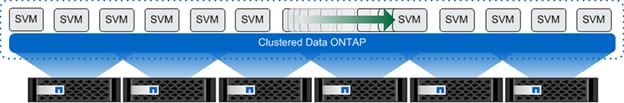
NetApp clustered Data ONTAP is the first product that offers a complete scale-out solution in an intelligent, adaptable, always-available storage infrastructure, utilizing proven storage efficiency for today's highly virtualized environments. Figure 1 depicts the organization of the NetApp scale-out solution.
Multiprotocol Unified Storage
Multiprotocol unified architecture supports multiple data access protocols concurrently in the same storage system over a whole range of different controller and disk storage types. Data ONTAP 7G and Data ONTAP operating in 7-Mode have long supported multiple protocols, and now clustered Data ONTAP supports an even wider range of data access protocols. Clustered Data ONTAP 8.2 supports the following protocols:
§ NFS v3, v4, and v4.1, including pNFS
§ SMB 1, 2, 2.1, and 3, including support for non-disruptive failover in Microsoft Hyper-V and Citrix PVS vDisk
§ iSCSI
§ Fibre Channel
§ FCoE
Multitenancy
Isolated servers and data storage can result in low utilization, gross inefficiency, and an inability to respond to changing business needs. Cloud architecture and delivering IT as a service (ITaaS) can overcome these limitations while reducing future IT expenditure.
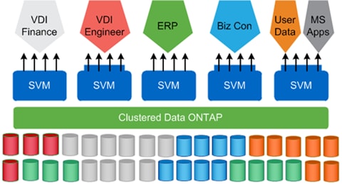
The storage virtual machine (SVM; formerly called Vserver) is the primary cluster logical component. Each SVM can create volumes, logical interfaces, and protocol access. With clustered Data ONTAP, each tenant's virtual desktops and data can be placed on different SVMs. The administrator of each SVM has the rights to provision volumes and other SVM-specific operations. This is particularly advantageous for service providers or any multitenant environments for which workload separation is desired.
Figure 2 shows the multitenancy concept in clustered Data ONTAP.
Cluster Management
For complete and consistent management of storage and SAN infrastructure, NetApp recommends using the tools listed in Table 1, unless specified otherwise.
Table 1 Cluster Management Tools
| Task | Management Tools |
| SVM management | NetApp OnCommand® System Manager |
| Switch management and zoning switch vendor | GUI or CLI interfaces |
| Volume and LUN provisioning and management | NetApp Virtual Storage Console for Citrix XenServer |
NetApp Storage Cluster Components
The following key terms are used throughout the remainder of this document:
§ Cluster. The information boundary and domain in which information travels. The cluster is where SVMs operate and also where high availability is defined between the physical nodes.
§ Node. A physical storage entity running Data ONTAP. This physical entity can be a traditional NetApp FAS controller; a supported third-party array front ended by a V-Series controller; or a NetApp virtual storage appliance (VSA) running Data ONTAP-v™.
§ SVM. A secure, virtualized storage controller that appears to end users as a physical entity (similar to a virtual machine [VM]). It is connected to one or more nodes through internal networking relationships (covered later in this document). An SVM is the highest element visible to an external consumer, and it abstracts the layer of interaction from the physical nodes. In other words, an SVM is used to provision cluster resources and can be compartmentalized in a secured manner to prevent access to other parts of the cluster.
Networking Concepts for Clustered Data ONTAP
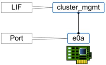
The physical interfaces on a node are called ports, and IP addresses are assigned to logical interfaces (LIFs). LIFs are logically connected to a port in much the same way that VM virtual network adapters and VMkernel ports are connected to physical adapters, except without the need for virtual switches and port groups. Physical ports can be grouped into interface groups, and VLANs can be created on top of physical ports or interface groups. LIFs can be associated with a port, interface group, or VLAN.
Figure 3 shows the clustered Data ONTAP networking concept.
Figure 3 Example of ports and LIFs
Storage Efficiency
Most desktop virtualization implementations deploy thousands of desktops from a small number of golden VM images, resulting in a large amount of duplicate data. This is particularly the case with the VM operating system.
The NetApp All Flash FAS (AFF) solution includes built-in thin provisioning, data deduplication, compression, and zero-cost cloning with NetApp FlexClone® technology. Customers get multilevel storage efficiency across virtual desktop data, installed applications, and user data. This comprehensive storage efficiency can significantly reduce the storage footprint for virtualized desktop implementations. Capacity can realistically be reduced by up to 10:1 or 90%, based on existing customer deployments and NetApp solutions lab validation.
The following features make this storage efficiency possible:
§ Thin provisioning allows multiple applications to share a single pool of on-demand storage. This capability eliminates the need to provision more storage for one application when another application still has plenty of allocated but unused storage. Thin provisioning is not really a storage efficiency technology because thin-provisioned VMs do not necessarily remain thin over time, but it can help increase utilization.
§ Inline deduplication saves space on primary storage by removing redundant copies of blocks in a volume that hosts hundreds of virtual desktops prior to writing the data to disks. This process is transparent to the application and the user, and it can be enabled and disabled dynamically by volume. To eliminate any potential concerns about deduplication causing additional wear on the SSDs, NetApp provides up to seven years of support at point-of-sale pricing. This support includes three years of standard and two plus two years of extended support, regardless of the number of drive writes per day. With AFF, deduplication can be run in an inline configuration to maintain storage efficiency over time.
§ FlexClone technology offers hardware-assisted rapid creation of space-efficient, writable, point-in-time images of individual VM files, LUNs, or flexible volumes. It is fully integrated with VMware vSphere vStorage APIs for Array Integration (VAAI) and Microsoft offloaded data transfer (ODX). The use of FlexClone technology in virtual desktop infrastructure deployments provides high levels of scalability and significant savings in cost, space, and time.
Both file-level and volume-level cloning are tightly integrated with the VMware vCenter Server. Integration is supported by the NetApp Virtual Storage Console Provisioning and Cloning vCenter plug-in and native VM cloning offload with VMware VAAI and Microsoft ODX. The Virtual Storage Console provides the flexibility to rapidly provision and redeploy thousands of VMs with hundreds of VMs in each datastore.
§ Inline pattern matching occurs when data is written to the storage system. Incoming data is received and hashed against existing data on the system. If the data is similar, it is marked for bit-for-bit comparison. Any zeros written to the system are removed through inline deduplication.
§ Inline zero deduplication saves space and improves performance by not writing zeroes. Doing so improves storage efficiency by eliminating the need to deduplicate the zeroes. This feature improves cloning time for eager-zeroed thick disk files and eliminates the zeroing of virtual machine disks (VMDKs) that require zeroing before data write, thus increasing SSD life expectancy. This feature is available in Data ONTAP 8.3 and later.
§ Inline compression saves space by compressing data as it enters the storage controller. Inline compression can be beneficial for the different data types that make up a virtual desktop environment. Each of these data types has different capacity and performance requirements, so some types might be better suited for inline compression than others. Using inline compression and deduplication together can significantly increase storage efficiency over using each independently.
§ Advanced drive partitioning distributes the root file system across multiple disks in an HA pair. It allows higher overall capacity utilization by removing the need for dedicated root and spare disks. This feature is available in Data ONTAP 8.3 and later.
Benefits of VMware vSphere ESXi 6.0
VMware vSphere® 6.0, the industry-leading virtualization platform, empowers users to virtualize any application with confidence, redefines availability, and simplifies the virtual data center. The result is a highly available, resilient, on-demand infrastructure that is the ideal foundation for any cloud environment. This blockbuster release contains the following new features and enhancements, many of which are industry-first features.
The following are some key features included with vSphere 6.0:
§ Increased Scalability
§ Expanded Support
§ Extended Graphics Support
§ Instant Clone
§ Storage Policy-Based Management
§ Network IO Control
§ Multicast Snooping
§ vMotion Enhancements
§ Expanded Software-Based Fault Tolerance
§ Enhanced User Interface
Benefits of Citrix XenApp and XenDesktop 7.7
Enterprise IT organizations are tasked with the challenge of provisioning Microsoft Windows apps and desktops while managing cost, centralizing control, and enforcing corporate security policy. Deploying Windows apps to users in any location, regardless of the device type and available network bandwidth, enables a mobile workforce that can improve productivity. With Citrix XenDesktop™ 7.7, IT can effectively control app and desktop provisioning while securing data assets and lowering capital and operating expenses.
The XenDesktop™ 7.7 release offers these benefits:
§ Comprehensive virtual desktop delivery for any use case. The XenDesktop 7.7 release incorporates the full power of XenApp, delivering full desktops or just applications to users. Administrators can deploy both XenApp published applications and desktops (to maximize IT control at low cost) or personalized VDI desktops (with simplified image management) from the same management console. Citrix XenDesktop 7.7 leverages common policies and cohesive tools to govern both infrastructure resources and user access.
§ Simplified support and choice of BYO (Bring Your Own) devices. XenDesktop 7.7 brings thousands of corporate Microsoft Windows-based applications to mobile devices with a native-touch experience and optimized performance. HDX technologies create a “high definition” user experience, even for graphics intensive design and engineering applications.
§ Lower cost and complexity of application and desktop management. XenDesktop 7.7 helps IT organizations take advantage of agile and cost-effective cloud offerings, allowing the virtualized infrastructure to flex and meet seasonal demands or the need for sudden capacity changes. IT organizations can deploy XenDesktop application and desktop workloads to private or public clouds.
§ Protection of sensitive information through centralization. XenDesktop decreases the risk of corporate data loss, enabling access while securing intellectual property and centralizing applications since assets reside in the datacenter.
This section describes the infrastructure components used in the solution outlined in this study.
Cisco Unified Computing System
Cisco UCS Manager provides unified, embedded management of all software and hardware components of the Cisco Unified Computing System™ (Cisco UCS) through an intuitive GUI, a command-line interface (CLI), and an XML API. The manager provides a unified management domain with centralized management capabilities and can control multiple chassis and thousands of virtual machines.
Cisco UCS is a next-generation data center platform that unites computing, networking, and storage access. The platform, optimized for virtual environments, is designed using open industry-standard technologies and aims to reduce total cost of ownership (TCO) and increase business agility. The system integrates a low-latency; lossless 10 Gigabit Ethernet unified network fabric with enterprise-class, x86-architecture servers. It is an integrated, scalable, multichassis platform in which all resources participate in a unified management domain.
Cisco Unified Computing System Components
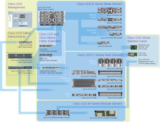
The main components of Cisco UCS (Figure 4) are:
§ Computing: The system is based on an entirely new class of computing system that incorporates blade servers based on Intel® Xeon® processor E5-2600/4600 v3 and E7-2800 v3 family CPUs.
§ Network: The system is integrated on a low-latency, lossless, 10-Gbps unified network fabric. This network foundation consolidates LANs, SANs, and high-performance computing (HPC) networks, which are separate networks today. The unified fabric lowers costs by reducing the number of network adapters, switches, and cables needed, and by decreasing the power and cooling requirements.
§ Virtualization: The system unleashes the full potential of virtualization by enhancing the scalability, performance, and operational control of virtual environments. Cisco security, policy enforcement, and diagnostic features are now extended into virtualized environments to better support changing business and IT requirements.
§ Storage access: The system provides consolidated access to local storage, SAN storage, and network-attached storage (NAS) over the unified fabric. With storage access unified, Cisco UCS can access storage over Ethernet, Fibre Channel, Fibre Channel over Ethernet (FCoE), and Small Computer System Interface over IP (iSCSI) protocols. This capability provides customers with choice for storage access and investment protection. In addition, server administrators can preassign storage-access policies for system connectivity to storage resources, simplifying storage connectivity and management and helping increase productivity.
§ Management: Cisco UCS uniquely integrates all system components, enabling the entire solution to be managed as a single entity by Cisco UCS Manager. The manager has an intuitive GUI, a CLI, and a robust API for managing all system configuration processes and operations.
Figure 4 Cisco Unified Computing System Components
Cisco UCS is designed to deliver:
§ Reduced TCO and increased business agility
§ Increased IT staff productivity through just-in-time provisioning and mobility support
§ A cohesive, integrated system that unifies the technology in the data center; the system is managed, serviced, and tested as a whole
§ Scalability through a design for hundreds of discrete servers and thousands of virtual machines and the capability to scale I/O bandwidth to match demand
§ Industry standards supported by a partner ecosystem of industry leaders
New Features in Cisco UCS Manager Release 3.1
Cisco UCS Manager, release 3.1 is a unified software release for all supported Cisco UCS hardware platforms. The release adds support for HTML5 interface in addition to the Java interface, both of which are available across all platforms
Cisco UCS Fabric Interconnect
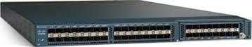
The Cisco UCS 6200 Series Fabric Interconnects are a core part of Cisco UCS, providing both network connectivity and management capabilities for the system. The Cisco UCS 6200 Series offers line-rate, low-latency, lossless 10 Gigabit Ethernet, FCoE, and Fibre Channel functions.
The fabric interconnects provide the management and communication backbone for the Cisco UCS B-Series Blade Servers and Cisco UCS 5100 Series Blade Server Chassis. All chassis, and therefore all blades, attached to the fabric interconnects become part of a single, highly available management domain. In addition, by supporting unified fabric, the Cisco UCS 6200 Series provides both LAN and SAN connectivity for all blades in the domain.
For networking, the Cisco UCS 6200 Series uses a cut-through architecture, supporting deterministic, low-latency, line-rate 10 Gigabit Ethernet on all ports, 1-terabit (Tb) switching capacity, and 160 Gbps of bandwidth per chassis, independent of packet size and enabled services. The product series supports Cisco low-latency, lossless, 10 Gigabit Ethernet unified network fabric capabilities, increasing the reliability, efficiency, and scalability of Ethernet networks. The fabric interconnects support multiple traffic classes over a lossless Ethernet fabric, from the blade server through the interconnect. Significant TCO savings come from an FCoE-optimized server design in which network interface cards (NICs), host bus adapters (HBAs), cables, and switches can be consolidated.
Figure 5 Cisco UCS 6200 Series Fabric Interconnect
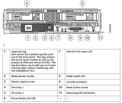
Cisco UCS B200 M4 Blade Server
The Cisco UCS B200 M4 Blade Server (Figures 2 and 3) is a density-optimized, half-width blade server that supports two CPU sockets for Intel Xeon processor E5-2600 v3 series CPUs and up to 24 DDR4 DIMMs. It supports one modular LAN-on-motherboard (LOM) dedicated slot for a Cisco virtual interface card (VIC) and one mezzanine adapter. In additions, the Cisco UCS B200 M4 supports an optional storage module that accommodates up to two SAS or SATA hard disk drives (HDDs) or solid-state disk (SSD) drives. You can install up to eight Cisco UCS B200 M4 servers in a chassis, mixing them with other models of Cisco UCS blade servers in the chassis if desired. Latest features of Cisco UCS Virtual Interface Cards (VICs)
Figure 6 Cisco UCS B200 M4 Front View
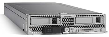
Figure 7 Cisco UCS B200 M4 Back View
Cisco UCS combines Cisco UCS B-Series Blade Servers and C-Series Rack Servers with networking and storage access into a single converged system with simplified management, greater cost efficiency and agility, and increased visibility and control. The Cisco UCS B200 M4 Blade Server is one of the newest servers in the Cisco UCS portfolio.
The Cisco UCS B200 M4 delivers performance, flexibility, and optimization for data centers and remote sites. This enterprise-class server offers market-leading performance, versatility, and density without compromise for workloads ranging from web infrastructure to distributed databases. The Cisco UCS B200 M4 can quickly deploy stateless physical and virtual workloads with the programmable ease of use of the Cisco UCS Manager software and simplified server access with Cisco® Single Connect technology. Based on the Intel Xeon processor E5-2600 v3 product family, it offers up to 768 GB of memory using 32-GB DIMMs, up to two disk drives, and up to 80 Gbps of I/O throughput. The Cisco UCS B200 M4 offers exceptional levels of performance, flexibility, and I/O throughput to run your most demanding applications.
In addition, Cisco UCS has the architectural advantage of not having to power and cool excess switches, NICs, and HBAs in each blade server chassis. With a larger power budget per blade server, it provides uncompromised expandability and capabilities, as in the new Cisco UCS B200 M4 server with its leading memory-slot capacity and drive capacity.
Cisco UCS B200 M4 Features
The Cisco UCS B200 M4 provides:
§ Up to two multicore Intel Xeon processor E5-2600 v3 series CPUs for up to 36 processing cores
§ 24 DIMM slots for industry-standard DDR4 memory at speeds up to 2133 MHz, and up to 768 GB of total memory when using 32-GB DIMMs
§ Two optional, hot-pluggable SAS and SATA HDDs or SSDs
§ Cisco UCS VIC 1340, a 2-port, 40 Gigabit Ethernet and FCoE–capable modular (mLOM) mezzanine adapter
— Provides two 40-Gbps unified I/O ports or two sets of four 10-Gbps unified I/O ports
— Delivers 80 Gbps to the server
— Adapts to either 10- or 40-Gbps fabric connections
§ Cisco FlexStorage local drive storage subsystem, with flexible boot and local storage capabilities that allow you to:
— Configure the Cisco UCS B200 M4 to meet your local storage requirements without having to buy, power, and cool components that you do not need
— Choose an enterprise-class RAID controller, or go without any controller or drive bays if you are not using local drives
— Easily add, change, and remove Cisco FlexStorage modules
The Cisco UCS B200 M4 server is a half-width blade. Up to eight can reside in the 6-rack-unit (6RU) Cisco UCS 5108 Blade Server Chassis, offering one of the highest densities of servers per rack unit of blade chassis in the industry.
Cisco UCS B200 M4 Benefits
The Cisco UCS B200 M4 server is well suited for a broad spectrum of IT workloads, including:
§ IT and web infrastructure
§ Virtualized workloads
§ Consolidating applications
§ Virtual desktops
§ Middleware
§ Enterprise resource planning (ERP) and customer-relationship management (CRM) applications
Single-Instance and Distributed Databases
The Cisco UCS B200 M4 is one member of the Cisco UCS B-Series Blade Servers platform. As part of Cisco UCS, Cisco UCS B-Series servers incorporate many innovative Cisco technologies to help customers handle their most challenging workloads. Cisco UCS B-Series servers within a Cisco UCS management framework incorporate a standards-based unified network fabric, Cisco Data Center Virtual Machine Fabric Extender (VM-FEX) virtualization support, Cisco UCS Manager, Cisco UCS Central Software, Cisco UCS Director software, and Cisco fabric extender architecture.
The Cisco UCS B200 M4 Blade Server delivers:
§ Suitability for a wide range of applications and workload requirements
§ Highest-performing CPU and memory options without constraints in configuration, power, or cooling
§ Half-width form factor that offers industry-leading benefits
§ Latest features of Cisco UCS VICs
For more information about the Cisco UCS B200 B4, see http://www.cisco.com/c/en/us/support/servers-unified-computing/ucs-b200-m4-blade-server/model.html
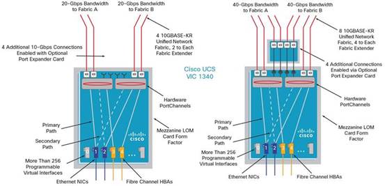
Cisco UCS VIC1340 Converged Network Adapter
The Cisco UCS Virtual Interface Card (VIC) 1340 (Figure 8) is a 2-port 40-Gbps Ethernet or dual 4 x 10-Gbps Ethernet, Fibre Channel over Ethernet (FCoE)-capable modular LAN on motherboard (mLOM) designed exclusively for the M4 generation of Cisco UCS B-Series Blade Servers. When used in combination with an optional port expander, the Cisco UCS VIC 1340 capabilities is enabled for two ports of 40-Gbps Ethernet.
The Cisco UCS VIC 1340 enables a policy-based, stateless, agile server infrastructure that can present over 256 PCIe standards-compliant interfaces to the host that can be dynamically configured as either network interface cards (NICs) or host bus adapters (HBAs). In addition, the Cisco UCS VIC 1340 supports Cisco® Data Center Virtual Machine Fabric Extender (VM-FEX) technology, which extends the Cisco UCS fabric interconnect ports to virtual machines, simplifying server virtualization deployment and management.
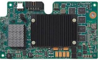
Figure 9 The Cisco UCS VIC 1340 Virtual Interface Cards Deployed in the Cisco UCS B-Series B200 M4 Blade Servers
Cisco Nexus 9372PX Switches
The Cisco Nexus 9372PX/9372PX-E Switches has 48 1/10-Gbps Small Form Pluggable Plus (SFP+) ports and 6 Quad SFP+ (QSFP+) uplink ports. All the ports are line rate, delivering 1.44 Tbps of throughput in a 1-rack-unit (1RU) form factor. Cisco Nexus 9372PX benefits are listed below.
Architectural Flexibility
§ Includes top-of-rack or middle-of-row fiber-based server access connectivity for traditional and leaf-spine architectures
§ Leaf node support for Cisco ACI architecture is provided in the roadmap
§ Increase scale and simplify management through Cisco Nexus 2000 Fabric Extender support
Feature Rich
§ Enhanced Cisco NX-OS Software is designed for performance, resiliency, scalability, manageability, and programmability
§ ACI-ready infrastructure helps users take advantage of automated policy-based systems management
§ Virtual Extensible LAN (VXLAN) routing provides network services
§ Cisco Nexus 9372PX-E supports IP-based endpoint group (EPG) classification in ACI mode
Highly Available and Efficient Design
§ High-density, non-blocking architecture
§ Easily deployed into either a hot-aisle and cold-aisle configuration
§ Redundant, hot-swappable power supplies and fan trays
Simplified Operations
§ Power-On Auto Provisioning (POAP) support allows for simplified software upgrades and configuration file installation
§ An intelligent API offers switch management through remote procedure calls (RPCs, JSON, or XML) over a HTTP/HTTPS infrastructure
§ Python Scripting for programmatic access to the switch command-line interface (CLI)
§ Hot and cold patching, and online diagnostics
Investment Protection
§ A Cisco 40 Gb bidirectional transceiver allows for reuse of an existing 10 Gigabit Ethernet multimode cabling plant for 40 Gigabit Ethernet
§ Support for 1 Gb and 10 Gb access connectivity for data centers migrating access switching infrastructure to faster speed
Supports
§ 1.44 Tbps of bandwidth in a 1 RU form factor
§ 48 fixed 1/10-Gbps SFP+ ports
§ 6 fixed 40-Gbps QSFP+ for uplink connectivity that can be turned into 10 Gb ports through a QSFP to SFP or SFP+ Adapter (QSA)
§ Latency of 1 to 2 microseconds
§ Front-to-back or back-to-front airflow configurations
§ 1+1 redundant hot-swappable 80 Plus Platinum-certified power supplies
§ Hot swappable 2+1 redundant fan tray
Cisco Nexus 1000V Distributed Virtual Switch
Get highly secure, multitenant services by adding virtualization intelligence to your data center network with the Cisco Nexus 1000V Switch for VMware vSphere. This switch does the following:
§ Extends the network edge to the hypervisor and virtual machines
§ Is built to scale for cloud networks
§ Forms the foundation of virtual network overlays for the Cisco Open Network Environment and Software Defined Networking (SDN)
Important Differentiators for the Cisco Nexus 1000V for VMware vSphere
§ Extensive virtual network services built on Cisco advanced service insertion and routing technology
§ Support for vCloud Director and vSphere hypervisor
§ Feature and management consistency for easy integration with the physical infrastructure
§ Exceptional policy and control features for comprehensive networking functionality
§ Policy management and control by the networking team instead of the server virtualization team (separation of duties)
Use Virtual Networking Services
The Cisco Nexus 1000V Switch optimizes the use of Layer 4 - 7 virtual networking services in virtual machine and cloud environments through Cisco vPath architecture services.
Cisco vPath 2.0 supports service chaining so you can use multiple virtual network services as part of a single traffic flow. For example, you can simply specify the network policy, and vPath 2.0 can direct traffic:
§ Second, through the Cisco Virtual Security Gateway for Nexus 1000V Switch for a zoning firewall
In addition, Cisco vPath works on VXLAN to support movement between servers in different Layer 2 domains. Together, these features promote highly secure policy, application, and service delivery in the cloud
Citrix XenApp and XenDesktop 7.7
Citrix XenApp and XenDesktop are application and desktop virtualization solutions built on a unified architecture so they're simple to manage and flexible enough to meet the needs of all your organization's users. XenApp and XenDesktop have a common set of management tools that simplify and automate IT tasks. You use the same architecture and management tools to manage public, private, and hybrid cloud deployments as you do for on premises deployments.
Citrix XenApp delivers the following:
§ XenApp published apps, also known as server-based hosted applications: These are applications hosted from Microsoft Windows servers to any type of device, including Windows PCs, Macs, smartphones, and tablets. Some XenApp editions include technologies that further optimize the experience of using Windows applications on a mobile device by automatically translating native mobile-device display, navigation, and controls to Windows applications; enhancing performance over mobile networks; and enabling developers to optimize any custom Windows application for any mobile environment.
§ XenApp published desktops, also known as server-hosted desktops: These are inexpensive, locked-down Windows virtual desktops hosted from Windows server operating systems. They are well suited for users, such as call center employees, who perform a standard set of tasks.
§ Virtual machine–hosted apps: These are applications hosted from machines running Windows desktop operating systems for applications that can’t be hosted in a server environment.
§ Windows applications delivered with Microsoft App-V: These applications use the same management tools that you use for the rest of your XenApp deployment.
§ Citrix XenDesktop 7.7: Includes significant enhancements to help customers deliver Windows apps and desktops as mobile services while addressing management complexity and associated costs. Enhancements in this release include:
§ Unified product architecture for XenApp and XenDesktop:The FlexCast Management Architecture (FMA). This release supplies a single set of administrative interfaces to deliver both hosted-shared applications (RDS) and complete virtual desktops (VDI). Unlike earlier releases that separately provisioned Citrix XenApp and XenDesktop farms, the XenDesktop 7.7 release allows administrators to deploy a single infrastructure and use a consistent set of tools to manage mixed application and desktop workloads.
§ Support for extending deployments to the cloud. This release provides the ability for hybrid cloud provisioning from Microsoft Azure, Amazon Web Services (AWS) or any Cloud Platform-powered public or private cloud. Cloud deployments are configured, managed, and monitored through the same administrative consoles as deployments on traditional on-premises infrastructure.
Citrix XenDesktop delivers:
§ VDI desktops: These virtual desktops each run a Microsoft Windows desktop operating system rather than running in a shared, server-based environment. They can provide users with their own desktops that they can fully personalize.
§ Hosted physical desktops: This solution is well suited for providing secure access powerful physical machines, such as blade servers, from within your data center.
§ Remote PC access: This solution allows users to log in to their physical Windows PC from anywhere over a secure XenDesktop connection.
§ Server VDI: This solution is designed to provide hosted desktops in multitenant, cloud environments.
§ Capabilities that allow users to continue to use their virtual desktops: These capabilities let users continue to work while not connected to your network.
This product release includes the following new and enhanced features:
![]() Some XenDesktop editions include the features available in XenApp.
Some XenDesktop editions include the features available in XenApp.
Zones
Deployments that span widely-dispersed locations connected by a WAN can face challenges due to network latency and reliability. Configuring zones can help users in remote regions connect to local resources without forcing connections to traverse large segments of the WAN. Using zones allows effective Site management from a single Citrix Studio console, Citrix Director, and the Site database. This saves the costs of deploying, staffing, licensing, and maintaining additional Sites containing separate databases in remote locations.
Zones can be helpful in deployments of all sizes. You can use zones to keep applications and desktops closer to end users, which improves performance.
For more information, see the Zones article.
Improved Database Flow and Configuration
When you configure the databases during Site creation, you can now specify separate locations for the Site, Logging, and Monitoring databases. Later, you can specify different locations for all three databases. In previous releases, all three databases were created at the same address, and you could not specify a different address for the Site database later.
You can now add more Delivery Controllers when you create a Site, as well as later. In previous releases, you could add more Controllers only after you created the Site.
For more information, see the Databases and Controllers articles.
Application Limits
Configure application limits to help manage application use. For example, you can use application limits to manage the number of users accessing an application simultaneously. Similarly, application limits can be used to manage the number of simultaneous instances of resource-intensive applications, this can help maintain server performance and prevent deterioration in service.
For more information, see the Manage applications article.
Multiple Notifications before Machine Updates or Scheduled Restarts
You can now choose to repeat a notification message that is sent to affected machines before the following types of actions begin:
§ Updating machines in a Machine Catalog using a new master image
§ Restarting machines in a Delivery Group according to a configured schedule
If you indicate that the first message should be sent to each affected machine 15 minutes before the update or restart begins, you can also specify that the message be repeated every five minutes until the update/restart begins.
For more information, see the Manage Machine Catalogs and Manage machines in Delivery Groups articles.
API Support for Managing Session Roaming
By default, sessions roam between client devices with the user. When the user launches a session and then moves to another device, the same session is used and applications are available on both devices. The applications follow, regardless of the device or whether current sessions exist. Similarly, printers and other resources assigned to the application follow.
![]() You can now use the PowerShell SDK to tailor session roaming. This was an experimental feature in the previous release.
You can now use the PowerShell SDK to tailor session roaming. This was an experimental feature in the previous release.
For more information, see the Sessions article.
API Support for Provisioning VMs from Hypervisor Templates
When using the PowerShell SDK to create or update a Machine Catalog, you can now select a template from other hypervisor connections. This is in addition to the currently-available choices of VM images and snapshots.
Support for New and Additional Platforms
See the System requirements article for full support information. Information about support for third-party product versions is updated periodically.
By default, SQL Server 2012 Express SP2 is installed when you install the Delivery Controller. SP1 is no longer installed.
The component installers now automatically deploy newer Microsoft Visual C++ runtime versions: 32-bit and 64-bit Microsoft Visual C++ 2013, 2010 SP1, and 2008 SP1. Visual C++ 2005 is no longer deployed.
You can install Studio or VDAs for Windows Desktop OS on machines running Windows 10.
You can create connections to Microsoft Azure virtualization resources.
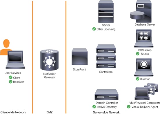
Figure 10 Logical Architecture of Citrix XenDesktop
Citrix Provisioning Services 7.7
Most enterprises struggle to keep up with the proliferation and management of computers in their environments. Each computer, whether it is a desktop PC, a server in a data center, or a kiosk-type device, must be managed as an individual entity. The benefits of distributed processing come at the cost of distributed management. It costs time and money to set up, update, support, and ultimately decommission each computer. The initial cost of the machine is often dwarfed by operating costs.
Citrix PVS takes a very different approach from traditional imaging solutions by fundamentally changing the relationship between hardware and the software that runs on it. By streaming a single shared disk image (vDisk) rather than copying images to individual machines, PVS enables organizations to reduce the number of disk images that they manage, even as the number of machines continues to grow, simultaneously providing the efficiency of centralized management and the benefits of distributed processing.
In addition, because machines are streaming disk data dynamically and in real time from a single shared image, machine image consistency is essentially ensured. At the same time, the configuration, applications, and even the OS of large pools of machines can be completed changed in the time it takes the machines to reboot.
Using PVS, any vDisk can be configured in standard-image mode. A vDisk in standard-image mode allows many computers to boot from it simultaneously, greatly reducing the number of images that must be maintained and the amount of storage that is required. The vDisk is in read-only format, and the image cannot be changed by target devices.
Benefits for Citrix XenApp and Other Server Farm Administrators
If you manage a pool of servers that work as a farm, such as Citrix XenApp servers or web servers, maintaining a uniform patch level on your servers can be difficult and time consuming. With traditional imaging solutions, you start with a clean golden master image, but as soon as a server is built with the master image, you must patch that individual server along with all the other individual servers. Rolling out patches to individual servers in your farm is not only inefficient, but the results can also be unreliable. Patches often fail on an individual server, and you may not realize you have a problem until users start complaining or the server has an outage. After that happens, getting the server resynchronized with the rest of the farm can be challenging, and sometimes a full reimaging of the machine is required.
With Citrix PVS, patch management for server farms is simple and reliable. You start by managing your golden image, and you continue to manage that single golden image. All patching is performed in one place and then streamed to your servers when they boot. Server build consistency is assured because all your servers use a single shared copy of the disk image. If a server becomes corrupted, simply reboot it, and it is instantly back to the known good state of your master image. Upgrades are extremely fast to implement. After you have your updated image ready for production, you simply assign the new image version to the servers and reboot them. You can deploy the new image to any number of servers in the time it takes them to reboot. Just as important, rollback can be performed in the same way, so problems with new images do not need to take your servers or your users out of commission for an extended period of time.
Benefits for Desktop Administrators
Because Citrix PVS is part of Citrix XenDesktop, desktop administrators can use PVS’s streaming technology to simplify, consolidate, and reduce the costs of both physical and virtual desktop delivery. Many organizations are beginning to explore desktop virtualization. Although virtualization addresses many of IT’s needs for consolidation and simplified management, deploying it also requires deployment of supporting infrastructure. Without PVS, storage costs can make desktop virtualization too costly for the IT budget. However, with PVS, IT can reduce the amount of storage required for VDI by as much as 90 percent. And with a single image to manage instead of hundreds or thousands of desktops, PVS significantly reduces the cost, effort, and complexity for desktop administration.
Different types of workers across the enterprise need different types of desktops. Some require simplicity and standardization, and others require high performance and personalization. XenDesktop can meet these requirements in a single solution using Citrix FlexCast delivery technology. With FlexCast, IT can deliver every type of virtual desktop, each specifically tailored to meet the performance, security, and flexibility requirements of each individual user.
Not all desktops applications can be supported by virtual desktops. For these scenarios, IT can still reap the benefits of consolidation and single-image management. Desktop images are stored and managed centrally in the data center and streamed to physical desktops on demand. This model works particularly well for standardized desktops such as those in lab and training environments and call centers and thin-client devices used to access virtual desktops.
Citrix Provisioning Services Solution
Citrix PVS streaming technology allows computers to be provisioned and re-provisioned in real time from a single shared disk image. With this approach, administrators can completely eliminate the need to manage and patch individual systems. Instead, all image management is performed on the master image. The local hard drive of each system can be used for runtime data caching or, in some scenarios, removed from the system entirely, which reduces power use, system failure rate, and security risk.
The PVS solution’s infrastructure is based on software-streaming technology. After PVS components are installed and configured, a vDisk is created from a device’s hard drive by taking a snapshot of the OS and application image and then storing that image as a vDisk file on the network. A device used for this process is referred to as a master target device. The devices that use the vDisks are called target devices. vDisks can exist on a PVS, file share, or in larger deployments, on a storage system with which PVS can communicate (iSCSI, SAN, network-attached storage [NAS], and Common Internet File System [CIFS]). vDisks can be assigned to a single target device in private-image mode, or to multiple target devices in standard-image mode.
Citrix Provisioning Services Infrastructure
The Citrix PVS infrastructure design directly relates to administrative roles within a PVS farm. The PVS administrator role determines which components that administrator can manage or view in the console.
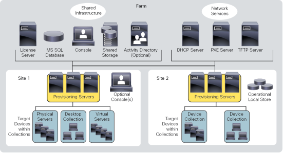
A PVS farm contains several components. Figure 11 provides a high-level view of a basic PVS infrastructure and shows how PVS components might appear within that implementation.
Figure 11 Logical Architecture of Citrix Provisioning Services
The following new features are available with Provisioning Services 7.7:
§ Streaming VHDX formatted disks
§ Support for Microsoft Windows 10 Enterprise and Professional editions
§ Support for Unified Extensible Firmware Interface (UEFI) enhancements
§ The licensing grace period for Provisioning Services has changed from 96 hours to 30 days, for consistency with XenApp and XenDesktop
§ Enhancements to API
§ vGPU-enabled XenDesktop machines can be provisioned using the Provisioning Services XenDesktop Setup Wizard
§ Support for System Center Virtual Machine Manager Generation 2 VMs
§ FIPS support
§ XenApp Session Recording Enabled by Default
NetApp AFF8000 Series
The Challenge
§ Enabling Data-Driven Business
— As technology has expanded to cover key business operations and back-office functions, IT leaders have had to rethink the way they architect storage. Traditional requirements such as storage uptime, scalability, and cost efficiency are still critical, but so are factors such as cloud integration, unified support for SAN and NAS, and simplified data mining for competitive advantage.
— Many enterprises struggle and are held back by structural limitations in legacy storage and data architectures. Traditional storage arrays might deliver on basic needs, but they are nonetheless incapable of meeting advanced service requirements and adapting to new IT models such as the cloud.
The Solution
§ Accelerate Business Operations with Unified Scale-Out Storage
— The demands of a data-driven business require a fundamentally new approach to storage, including an integrated combination of high-performance hardware and adaptive, scalable storage software. This new approach must support existing workloads as well as adapt and scale quickly to address new applications and evolving IT models.
— NetApp FAS8000 enterprise storage systems are specifically engineered to address these needs. Powered by Data ONTAP and optimized for scale-out, the FAS8000 series unifies your SAN and NAS storage infrastructure. With proven data management capabilities, the FAS8000 has the flexibility to keep up with changing business needs while delivering on core IT requirements.
— The FAS8000 features a multiprocessor Intel chip set and leverages high-performance memory modules, NVRAM to accelerate and optimize writes, and an I/O-tuned PCIe gen3 architecture that maximizes application throughput. Building on a decade of multicore optimization, Data ONTAP drives the latest cores and increased core counts to keep up with continuous growth in storage demands. The result is a flexible, efficient I/O design capable of supporting large numbers of high-speed network connections and massive capacity scaling.
— FAS8000 scale-out storage systems offer exceptional flexibility and expandability. Integrated unified target adapter (UTA2) ports support 16Gb Fibre Channel, 10GbE, and FCoE, so your storage is ready on day one for whatever changes the future requires.
The FAS 8000 provides the following key benefits:
§ Support more workloads. Run SAN and NAS workloads simultaneously with the industry’s only unified scale-out storage.
§ Consolidate infrastructure. Expand scaling up to 103PB and include existing storage with NetApp FlexArray™ storage virtualization software.
§ Accelerate I/O-intensive apps. Reduce latency and speed operations with up to 1.7PB of hybrid flash.
§ Maximize uptime. Experience >99.999% availability and nondisruptive operations that eliminate planned downtime.
§ Realize superior value. Deliver up to 2x the price and performance of the previous generation.
§ Optimized for the hybrid cloud. Easily implement a service-oriented IT architecture that spans on-premises and off-site resources.
Figure 12 NetApp AFF8000 Controllers
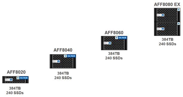
For performance-intensive environments where maximum scale and I/O throughput are necessary to drive business-critical applications, NetApp offers the FAS8080 EX. For more information, see the AFF8080 EX datasheet.
§ Get More From Existing Storage Investments
Simplify your IT operations and deliver more value from existing storage with the only unified storage virtualization solution. FlexArray virtualization software running on a FAS8000 extends the capabilities of Data ONTAP to include storage capacity from EMC, Hitachi, HP, and NetApp E-Series arrays. Consolidate management of your existing storage to increase efficiency and provide superior functionality. This software creates a single storage management architecture that supports both SAN and NAS while simplifying management and cloud integration.
§ Scale and Adapt to Meet Changing Needs
Your business is constantly changing, and your storage infrastructure should adapt and scale right along with it. With FAS8000 unified scale-out storage, you can optimize and accelerate your storage environment as needed. All FAS8000 storage is designed to scale as performance and capacity requirements change. You can scale up by adding capacity, adding flash acceleration, and upgrading controllers and also scale out. A single cluster can accommodate up to 24 nodes and 103PB of capacity with ease. You can non-disruptively add or replace storage systems and components and mix and match different FAS models. Therefore, scaling occurs without maintenance windows or the challenge of coordinating downtime across teams.
§ Unlock the Full Power of Flash
Flash-accelerated FAS8000 storage systems deliver twice the performance of our previous generation of storage, boosting throughput, lowering latency, and meeting stringent service levels with predictable high performance. Data ONTAP on the FAS8000 simplifies flash management, resulting in more powerful hybrid storage.
In hybrid FAS8000 configurations, flash functions as a self-managing virtual storage tier with up to 144TB of flash per HA pair and 1.7PB per cluster. Hot data is automatically promoted to flash in real time, so you get the full benefit of flash performance. The NetApp AFF family of flash arrays is optimized for applications that require high performance, low latency, and rich data management. For more information, see the All Flash FAS datasheet.
§ Enable Innovation and Empower Users
In a data-driven business, performance and capacity alone are not enough. You must leverage data for competitive advantage and assign resources dynamically for more effective operations. The NetApp OnCommand® storage management software portfolio is composed of a range of products for use with the NetApp FAS8000, including device-level management, automation, integration, and enterprise storage resource management.
NetApp OnCommand software provides flexibility, scalability, simplified provisioning, and data protection to meet business needs today and changing needs in the future.
§ Achieve Unparalleled Availability and Nondisruptive Operations
FAS8000 enterprise storage is engineered to meet the most demanding availability requirements. All models are designed to deliver 99.999% or greater availability through a comprehensive approach that combines highly reliable hardware, innovative software, and sophisticated service analytics. Software and firmware updates, hardware repair and replacement, load balancing, and tech refresh happen without planned downtime.
NetApp Integrated Data Protection technologies protect your data, accelerate recovery, and integrate with leading backup applications for easier management. Advanced service analytics software prevents issues from becoming outages. Risk signatures are constantly monitored, and your administrators and/or NetApp service staff are alerted to proactively address issues that might affect operations.
NetApp MetroCluster™ high-availability and disaster recovery software expands data protection to eliminate risk of data loss by synchronously mirroring data between locations for continuous availability of information. A MetroCluster storage array can exist in a single data center or in two different data centers that are located across a campus, across a metropolitan area, or in different cities altogether. MetroCluster provides data protection combined with continuous data availability. This means that no matter what happens, your data can be protected from loss and is continuously available to meet the most business-critical needs.
§ Build the Right Long-Term Platform
When it comes to long-term storage infrastructure investments, total cost of ownership and the ability to accommodate new IT initiatives are critical. FAS8000 enterprise storage systems unlock the power of your data and your people. In addition to a significant price and performance benefit—up to two times that of the previous generation—the FAS8000 platform delivers industry-leading storage efficiency technologies such as deduplication, compression, thin provisioning, and space-efficient Snapshot® copies. This reduces your cost per effective gigabyte of storage.
§ Optimize Hybrid Cloud Deployment
Organizations today are focusing on service-oriented IT architectures in which cloud IT models enhance return on investment and assets. A FAS8000 running Data ONTAP is optimized for private and hybrid cloud computing environments with secure multi-tenancy, quality of service (QoS), nondisruptive operations, and easily defined tiers of service. A FAS8000 tightly integrated with the industry standard OpenStack cloud infrastructure enables you to build a private cloud that delivers a leading service-oriented architecture and meets the significant demands of enterprise applications.
For organizations that require an enterprise-class hybrid cloud with predictable performance and availability, the FAS8000 can be used in a NetApp Private Storage (NPS) for Cloud solution. With NPS for Cloud you can directly connect to multiple clouds by using a private, high-bandwidth, low-latency connection. You can connect to industry-leading clouds such as Amazon Web Services (AWS), Microsoft Azure, or SoftLayer and switch between them at any time. NPS for Cloud delivers complete control of your data on your dedicated, private FAS8000.
With NetApp technologies, you get the elasticity of the public cloud and critical protection for your data that you understand and trust. For maximum flexibility, NetApp Cloud ONTAP® provides superior data portability at the best ROI. Cloud ONTAP is a software-defined storage version of Data ONTAP that runs in AWS and provides the storage efficiency, availability, and scalability of Data ONTAP. This storage solution enables quick and easy movement of data between your on-premises FAS8000 and AWS environments by using NetApp SnapMirror® data replication software.
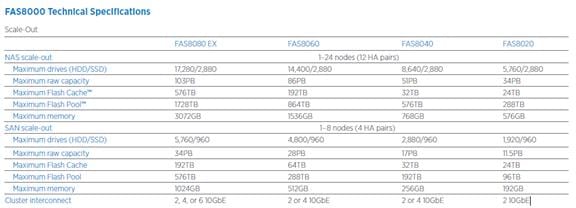
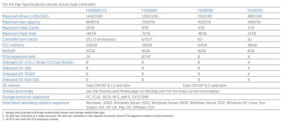
NetApp AFF8080EX-A Used in Testing
The Solution
Support for business-critical requirements in financial modeling, engineering analysis, and data warehousing thought impossible only five years ago is now realizable with the NetApp® FAS8080 EX. Designed to deliver superior levels of performance, availability, and scalability, the FAS8080 EX transforms storage into a strategic operational resource for generating revenue more quickly.
Powered by NetApp Data ONTAP®, the FAS8080 EX is optimized at every level for enterprise applications. Forty processor cores, 256GB of high-speed DRAM, capacity for 1,440 drives, and 144TB of hybrid flash acceleration are balanced together in a high-availability (HA) pair to reliably process the massive amounts of data in a modern enterprise. With 16 onboard I/O ports as well as 24 PCIe 3.0 expansion slots, serving data to applications has never been easier. Combine this with world-class data management from Data ONTAP, and you have a system that can reduce the time it takes to complete critical operations, increase your organization’s competitive advantage, and keep your enterprise applications running at top speed 24/7/365.
The AFF8080 EX is available for workloads requiring the high performance and low latency of an all flash array with the enterprise reliability and extensive data management capabilities of Data ONTAP. See the All Flash FAS datasheet for details.
Performance for Extraordinary Throughput
Our leading Intel multiprocessor architecture with its high bandwidth DDR3 memory system maximizes throughput for business-critical workloads such as SAP, SQL Server, and Oracle databases as well as computational modeling and logistics management applications. Building on a decade of multicore optimizations, Data ONTAP takes advantage of the FAS8080 EX’s 40 processor cores to keep pace with growth in storage I/O demands for your most intensive SAN and NAS applications. Integrated unified target adapter (UTA2) ports support 16Gb FC and 10GbE (FCoE, iSCSI, SMB, NFS) so you’re ready for whatever the future holds. Twenty-four I/O-tuned PCIe gen3 slots support Flash Cache™ cards or up to 48 extra 10GbE or 16Gb FC ports for demanding data-processing installations.
Flash-Accelerated Productivity
For OLTP databases and other business-critical workloads that require a storage solution with rich data management features, the FAS8080 EX delivers increased performance and lower latency. The response times of OLTP and other business-critical workloads can be significantly improved with a FAS8080 EX hybrid storage array. Proven examples demonstrate that shifting an OLTP database workload from an all-SAS to a hybrid array with flash and SATA can lower cost per TB by more than 40 percent, lower cost per IOPS by almost 20 percent, and reduce power consumption by over 25 percent. Hybrid FAS8080 EX systems boost performance and lower latency for your IT operations, so they are more predictable to meet stringent service-level objectives. Flash functions as a self-managing virtual storage tier with up to 144TB of hybrid flash per HA pair and 1.7PB per cluster. The FAS8080 EX offers flexibility to configure a system for optimal productivity and predictability to keep operations running smoothly.
Figure 13 Multi-Tenant Virtual Infrastructure
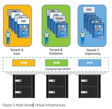
Capacity to Harness the Data Explosion
Storage scale-out to more than 17,000 drives and 4M IOPS of performance combined with the industry-leading management capabilities of Data ONTAP enables the FAS8080 EX to process petabytes of data for complex resource exploration, faster semiconductor chip design, or optimally managing logistics for billion-dollar-plus product operations. 103PB of data in a 24-node cluster can be managed from a single console to reduce the cost of operations and simplify warehousing years of business-critical data.
Identify Problems Before They Happen to Achieve Unparalleled Availability and Stringent SLOs
As with other business-critical arrays, the FAS8080 EX is designed to deliver 99.999 percent or greater availability through a comprehensive approach that combines highly reliable hardware, innovative software, and sophisticated service analytics. Advanced hardware features, including alternate control path (ACP), persistent NVRAM write logs, and an integrated service processor, provide the utmost reliability to protect your investment. All I/O devices, including embedded ports, can be independently reset, allowing the FAS8080 EX to detect, contain, and recover from faults.
NetApp builds upon the resilient hardware platform with advanced software capabilities that further improve uptime. Meet the most demanding SLOs with Data ONTAP nondisruptive operations (NDO), quality of service (QoS), and integrated data protection capabilities. NDO enables software and firmware updates, hardware repair and replacement, load balancing, and tech refresh to happen without planned downtime. QoS makes sure that applications have access to the resources they need. NetApp Integrated Data Protection technologies protect your data, accelerate recovery, and integrate with leading backup applications for easier management.
At NetApp, we use advanced service analytics to identify patterns in billions of rows of log data gathered from thousands of deployed NetApp systems. Risk signatures are constantly monitored, and your administrators and/or NetApp service staff are alerted to proactively address issues that might affect operations. NetApp MetroCluster™ expands data protection to eliminate risk of data loss by synchronously mirroring data between locations for continuous availability of information. A MetroCluster storage array can exist in a single data center or in two different data centers that are located across a campus, across a metropolitan area, or in different cities altogether. MetroCluster provides data protection combined with continuous data availability. This means that no matter what happens, your data can be protected from loss and is continuously available to meet the most business-critical needs.
Get More from Existing Storage Investments
Extend the capabilities of the FAS8080 EX to include EMC, Hitachi, HP, and NetApp E-Series arrays with FlexArray® virtualization software. Consolidate management of your existing storage to simplify operations, while increasing efficiency and providing superior functionality with FlexArray, the only unified storage virtualization solution.With FlexArray, create a single storage management architecture that supports both SAN and NAS while simplifying management and cloud integration.
Optimize Hybrid Cloud Deployment
Organizations today are focusing on service-oriented IT architectures where cloud IT models are leveraged to enhance return on investment and assets. The FAS8080 EX is optimized for private and hybrid cloud with secure multi-tenancy, QoS, nondisruptive operations, and easily defined tiers of service. A FAS8080 EX tightly integrated with the industry standard OpenStack cloud infrastructure enables an organization to build a private cloud that delivers a leading service-oriented IT architecture and meets the demanding needs of enterprise applications. For organizations that need an enterprise-class hybrid cloud with predictable performance and availability, the FAS8080 EX can be used in a NetApp Private Storage (NPS) for Cloud solution.
With NPS for Cloud you can directly connect to multiple clouds using a private, high-bandwidth, low-latency connection. Connect to industry-leading clouds such as Amazon Web Services (AWS), Microsoft Azure, or SoftLayer and switch between them at any time, all while maintaining complete control of your data on your dedicated, private FAS8080 EX. You get the elasticity of the public cloud and protect your data with NetApp technologies that you understand and trust.
For maximum flexibility, Cloud ONTAP™ provides superior data portability at the best ROI. Cloud ONTAP is a software-defined storage version of Data ONTAP that runs in AWS and provides the storage efficiency, availability, and scalability of Data ONTAP. It allows quick and easy movement of data between your on-premises FAS8080 EX and AWS environments with NetApp SnapMirror® data replication software.
Get More Business Value with Services
Whether you are planning your next-generation environment, need specialized know-how for a major deployment, or want to get the most from your current storage, NetApp and our certified partners can help. We collaborate with you to enhance your IT capabilities through a full portfolio of services that covers your IT lifecycle with:
§ Strategy services to align IT with your business goals:
§ Design services to architect your best storage environment
§ Deploy and transition services to implement validated architectures and prepare your storage environment
§ Operations services to deliver continuous operations while driving operational excellence and efficiency.
In addition, NetApp provides in-depth knowledge transfer and education services that give you access to our global technical resources and intellectual property.
VMware vSphere 6.0
VMware provides virtualization software. VMware’s enterprise software hypervisors for servers—VMware vSphere ESX, vSphere ESXi, and VSphere—are bare-metal hypervisors that run directly on server hardware without requiring an additional underlying operating system. VMware vCenter Server for vSphere provides central management and complete control and visibility into clusters, hosts, virtual machines, storage, networking, and other critical elements of your virtual infrastructure.
VMware vSphere 6.0 introduces many enhancements to vSphere Hypervisor, VMware virtual machines, vCenter Server, virtual storage, and virtual networking, further extending the core capabilities of the vSphere platform.
VMware ESXi 6.0 Hypervisor
vSphere 6.0 introduces a number of new features in the hypervisor:
§ Scalability Improvements
ESXi 6.0 dramatically increases the scalability of the platform. With vSphere Hypervisor 6.0, clusters can scale to as many as 64 hosts, up from 32 in previous releases. With 64 hosts in a cluster, vSphere 6.0 can support 8000 virtual machines in a single cluster. This capability enables greater consolidation ratios, more efficient use of VMware vSphere Distributed Resource Scheduler (DRS), and fewer clusters that must be separately managed. Each vSphere Hypervisor 6.0 instance can support up to 480 logical CPUs, 12 terabytes (TB) of RAM, and 1024 virtual machines. By using the newest hardware advances, ESXi 6.0 enables the virtualization of applications that previously had been thought to be nonvirtualizable.
§ Security Enhancements
— ESXi 6.0 offers these security enhancements:
o Account management: ESXi 6.0 enables management of local accounts on the ESXi server using new ESXi CLI commands. The capability to add, list, remove, and modify accounts across all hosts in a cluster can be centrally managed using a vCenter Server system. Previously, the account and permission management functions for ESXi hosts were available only for direct host connections. The setup, removal, and listing of local permissions on ESXi servers can also be centrally managed.
o Account lockout: ESXi Host Advanced System Settings have two new options for the management of failed local account login attempts and account lockout duration. These parameters affect Secure Shell (SSH) and vSphere Web Services connections, but not ESXi direct console user interface (DCUI) or console shell access.
o Password complexity rules: In previous versions of ESXi, password complexity changes had to be made by manually editing the /etc/pam.d/passwd file on each ESXi host. In vSphere 6.0, an entry in Host Advanced System Settings enables changes to be centrally managed for all hosts in a cluster.
o Improved auditability of ESXi administrator actions: Prior to vSphere 6.0, actions at the vCenter Server level by a named user appeared in ESXi logs with the vpxuser username: for example, [user=vpxuser]. In vSphere 6.0, all actions at the vCenter Server level for an ESXi server appear in the ESXi logs with the vCenter Server username: for example, [user=vpxuser: DOMAIN\User]. This approach provides a better audit trail for actions run on a vCenter Server instance that conducted corresponding tasks on the ESXi hosts.
o Flexible lockdown modes: Prior to vSphere 6.0, only one lockdown mode was available. Feedback from customers indicated that this lockdown mode was inflexible in some use cases. With vSphere 6.0, two lockdown modes are available:
§ In normal lockdown mode, DCUI access is not stopped, and users on the DCUI access list can access the DCUI.
§ In strict lockdown mode, the DCUI is stopped.
o Exception users: vSphere 6.0 offers a new function called exception users. Exception users are local accounts or Microsoft Active Directory accounts with permissions defined locally on the host to which these users have host access. These exception users are not recommended for general user accounts, but they are recommended for use by third-party applications—for service accounts, for example—that need host access when either normal or strict lockdown mode is enabled. Permissions on these accounts should be set to the bare minimum required for the application to perform its task and with an account that needs only read-only permissions on the ESXi host.
o Smart card authentication to DCUI: This function is for U.S. federal customers only. It enables DCUI login access using a Common Access Card (CAC) and Personal Identity Verification (PIV). The ESXi host must be part of an Active Directory domain.
Cisco Desktop Virtualization Solutions: Data Center
The Evolving Workplace
Today’s IT departments are facing a rapidly evolving workplace environment. The workforce is becoming increasingly diverse and geographically dispersed, including offshore contractors, distributed call center operations, knowledge and task workers, partners, consultants, and executives connecting from locations around the world at all times.
This workforce is also increasingly mobile, conducting business in traditional offices, conference rooms across the enterprise campus, home offices, on the road, in hotels, and at the local coffee shop. This workforce wants to use a growing array of client computing and mobile devices that they can choose based on personal preference. These trends are increasing pressure on IT to ensure protection of corporate data and prevent data leakage or loss through any combination of user, endpoint device, and desktop access scenarios (Figure 14).
These challenges are compounded by desktop refresh cycles to accommodate aging PCs and bounded local storage and migration to new operating systems, specifically Microsoft Windows 10.
Figure 14 Cisco Desktop Virtualization Solutions
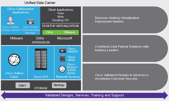
Some of the key drivers for desktop virtualization are increased data security and reduced TCO through increased control and reduced management costs.
Cisco Desktop Virtualization Focus
Cisco focuses on three key elements to deliver the best desktop virtualization data center infrastructure: simplification, security, and scalability. The software combined with platform modularity provides a simplified, secure, and scalable desktop virtualization platform.
Simplified
Cisco UCS provides a radical new approach to industry-standard computing and provides the core of the data center infrastructure for desktop virtualization. Among the many features and benefits of Cisco UCS are the drastic reduction in the number of servers needed and in the number of cables used per server, and the capability to rapidly deploy or reprovision servers through Cisco UCS service profiles. With fewer servers and cables to manage and with streamlined server and virtual desktop provisioning, operations are significantly simplified. Thousands of desktops can be provisioned in minutes with Cisco UCS Manager service profiles and Cisco storage partners’ storage-based cloning. This approach accelerates the time to productivity for end users, improves business agility, and allows IT resources to be allocated to other tasks.
Cisco UCS Manager automates many mundane, error-prone data center operations such as configuration and provisioning of server, network, and storage access infrastructure. In addition, Cisco UCS B-Series Blade Servers and C-Series Rack Servers with large memory footprints enable high desktop density that helps reduce server infrastructure requirements.
Simplification also leads to more successful desktop virtualization implementation. Cisco and its technology partners like Citrix (Citrix XenDesktop), and NetApp (NetApp FAS) have developed integrated, validated architectures, including predefined converged architecture infrastructure packages such as FlexPod. Cisco Desktop Virtualization Solutions have been tested with all the leading hypervisors, including VMware vSphere, Citrix XenServer, and Microsoft Hyper-V.
Secure
Although virtual desktops are inherently more secure than their physical predecessors, they introduce new security challenges. Mission-critical web and application servers using a common infrastructure such as virtual desktops are now at a higher risk for security threats. Inter–virtual machine traffic now poses an important security consideration that IT managers need to address, especially in dynamic environments in which virtual machines, using VMware vMotion, move across the server infrastructure.
Desktop virtualization, therefore, significantly increases the need for virtual machine–level awareness of policy and security, especially given the dynamic and fluid nature of virtual machine mobility across an extended computing infrastructure. The ease with which new virtual desktops can proliferate magnifies the importance of a virtualization-aware network and security infrastructure. Cisco data center infrastructure (Cisco UCS and Cisco Nexus Family solutions) for desktop virtualization provides strong data center, network, and desktop security, with comprehensive security from the desktop to the hypervisor. Security is enhanced with segmentation of virtual desktops, virtual machine–aware policies and administration, and network security across the LAN and WAN infrastructure.
Scalable
Growth of a desktop virtualization solution is all but inevitable, so a solution must be able to scale, and scale predictably, with that growth. The Cisco Desktop Virtualization Solutions support high virtual-desktop density (desktops per server), and additional servers scale with near-linear performance. Cisco data center infrastructure provides a flexible platform for growth and improves business agility. Cisco UCS Manager service profiles allow on-demand desktop provisioning and make it just as easy to deploy dozens of desktops as it is to deploy thousands of desktops.
Cisco UCS servers provide near-linear performance and scale. Cisco UCS implements the patented Cisco Extended Memory Technology to offer large memory footprints with fewer sockets (with scalability to up to 1 terabyte (TB) of memory with 2- and 4-socket servers). Using unified fabric technology as a building block, Cisco UCS server aggregate bandwidth can scale to up to 80 Gbps per server, and the northbound Cisco UCS fabric interconnect can output 2 terabits per second (Tbps) at line rate, helping prevent desktop virtualization I/O and memory bottlenecks. Cisco UCS, with its high-performance, low-latency unified fabric-based networking architecture, supports high volumes of virtual desktop traffic, including high-resolution video and communications traffic. In addition, Cisco storage partners NetApp help maintain data availability and optimal performance during boot and login storms as part of the Cisco Desktop Virtualization Solutions. Recent Cisco Validated Designs based on Citrix, Cisco UCS, and NetApp joint solutions have demonstrated scalability and performance, with up to 5000 desktops up and running in 30 minutes.
Cisco UCS and Cisco Nexus data center infrastructure provides an excellent platform for growth, with transparent scaling of server, network, and storage resources to support desktop virtualization, data center applications, and cloud computing.
Savings and Success
The simplified, secure, scalable Cisco data center infrastructure for desktop virtualization solutions saves time and money compared to alternative approaches. Cisco UCS enables faster payback and ongoing savings (better ROI and lower TCO) and provides the industry’s greatest virtual desktop density per server, reducing both capital expenditures (CapEx) and operating expenses (OpEx). The Cisco UCS architecture and Cisco Unified Fabric also enables much lower network infrastructure costs, with fewer cables per server and fewer ports required. In addition, storage tiering and deduplication technologies decrease storage costs, reducing desktop storage needs by up to 50 percent.
The simplified deployment of Cisco UCS for desktop virtualization accelerates the time to productivity and enhances business agility. IT staff and end users are more productive more quickly, and the business can respond to new opportunities quickly by deploying virtual desktops whenever and wherever they are needed. The high-performance Cisco systems and network deliver a near-native end-user experience, allowing users to be productive anytime and anywhere.
The ultimate measure of desktop virtualization for any organization is its efficiency and effectiveness in both the near term and the long term. The Cisco Desktop Virtualization Solutions are very efficient, allowing rapid deployment, requiring fewer devices and cables, and reducing costs. The solutions are also very effective, providing the services that end users need on their devices of choice while improving IT operations, control, and data security. Success is bolstered through Cisco’s best-in-class partnerships with leaders in virtualization and storage, and through tested and validated designs and services to help customers throughout the solution lifecycle. Long-term success is enabled through the use of Cisco’s scalable, flexible, and secure architecture as the platform for desktop virtualization.
Use Cases
§ Healthcare: Mobility between desktops and terminals, compliance, and cost
§ Federal government: Teleworking initiatives, business continuance, continuity of operations (COOP), and training centers
§ Financial: Retail banks reducing IT costs, insurance agents, compliance, and privacy
§ Education: K-12 student access, higher education, and remote learning
§ State and local governments: IT and service consolidation across agencies and interagency security
§ Retail: Branch-office IT cost reduction and remote vendors
§ Manufacturing: Task and knowledge workers and offshore contractors
§ Microsoft Windows 7 migration
§ Security and compliance initiatives
§ Opening of remote and branch offices or offshore facilities
§ Mergers and acquisitions
Cisco Nexus 9372TX Switch
This section describes the Cisco networking infrastructure components used in the configuration.
The Cisco Nexus 9372TX Switch has 48 1/10GBase-T ports that can operate at 100 Mbps, 1 Gbps, and 10 Gbps speeds and six Quad Small Form Pluggable Plus (QSFP+) uplink ports. All ports are line rate, delivering 1.44 Tbps of throughput in a 1-rack-unit (1RU) form factor. Nexus 9372TX benefits are listed below:
Architectural Flexibility
§ Includes top-of-rack or middle-of-row copper-based server access connectivity
§ Includes a leaf node in a spine-leaf architecture for low-latency traffic flow and reduced convergence time in the event of a failure
Feature-Rich
§ Includes an enhanced version of Cisco NX-OS Software designed for performance, resiliency, scalability, manageability, and programmability
§ ACI-ready hardware infrastructure allows users to take full advantage of an automated, policy-based, systems management approach
§ Supports virtual extensible LAN (VXLAN) routing
§ An additional 25 MB buffer is included, surpassing competing switch offerings
Highly Available and Efficient Design
§ High-density, non-blocking architecture
§ Easily deployed into either a hot-aisle and cold-aisle configuration
§ Redundant, hot-swappable power supplies and fan trays
Simplified Operations
§ Power-On Auto Provisioning (POAP) support allows for simplified software upgrades and configuration file installation
§ An intelligent API offers switch management through remote procedure calls (RPCs, JSON, or XML) over a HTTP/HTTPS infrastructure
§ Python Scripting for programmatic access to the switch command-line interface (CLI)
§ Hot and cold patching, and online diagnostics
Investment Protection
§ A Cisco 40 Gb bidirectional transceiver allows for reuse of an existing 10 Gigabit Ethernet multimode cabling plant for 40 Gigabit Ethernet
§ Support for 100 Mb, 1 Gb, and 10 Gb access connectivity for data centers migrating access switching infrastructure to faster speeds
Specifications At-a-Glance
§ 1.44 Tbps of bandwidth in a 1 RU form factor
§ 48 fixed 1/10-Gbps BASE-T ports that can operate at 100 Mbps, 1 Gbps, or 10 Gbps speeds
§ 6 fixed 40-Gbps QSFP+ for uplink connectivity that can be turned into 10 Gb ports through a Qualified Security Assessor (QSA) adapter
§ Latency of 1 to 2 microseconds
§ Front-to-back or back-to-front airflow configurations
§ 1+1 redundant hot-swappable 80 Plus Platinum-certified power supplies
§ Hot swappable 2+1 redundant fan trays
Figure 15 Cisco Nexus 9372TX Switch
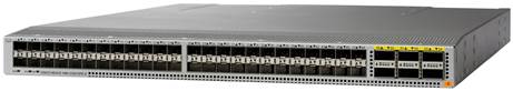
Architecture and Design of XenDesktop 7.7 on Cisco Unified Computing System and NetApp AFF Storage Design Fundamentals
There are many reasons to consider a virtual desktop solution such as an ever growing and diverse base of user devices, complexity in management of traditional desktops, security, and even Bring Your Own Computer (BYOC) to work programs. The first step in designing a virtual desktop solution is to understand the user community and the type of tasks that are required to successfully execute their role. The following user classifications are provided:
§ Knowledge Workers today do not just work in their offices all day – they attend meetings, visit branch offices, work from home, and even coffee shops. These anywhere workers expect access to all of their same applications and data wherever they are.
§ External Contractors are increasingly part of your everyday business. They need access to certain portions of your applications and data, yet administrators still have little control over the devices they use and the locations they work from. Consequently, IT is stuck making trade-offs on the cost of providing these workers a device vs. the security risk of allowing them access from their own devices.
§ Task Workers perform a set of well-defined tasks. These workers access a small set of applications and have limited requirements from their PCs. However, since these workers are interacting with your customers, partners, and employees, they have access to your most critical data.
§ Mobile Workers need access to their virtual desktop from everywhere, regardless of their ability to connect to a network. In addition, these workers expect the ability to personalize their PCs, by installing their own applications and storing their own data, such as photos and music, on these devices.
§ Shared Workstation users are often found in state-of-the-art university and business computer labs, conference rooms or training centers. Shared workstation environments have the constant requirement to re-provision desktops with the latest operating systems and applications as the needs of the organization change, tops the list.
After the user classifications have been identified and the business requirements for each user classification have been defined, it becomes essential to evaluate the types of virtual desktops that are needed based on user requirements. There are essentially five potential desktops environments for each user:
§ Traditional PC: A traditional PC is what ―typically‖ constituted a desktop environment: physical device with a locally installed operating system.
§ Hosted Shared Desktop: A hosted, server-based desktop is a desktop where the user interacts through a delivery protocol. With hosted, server-based desktops, a single installed instance of a server operating system, such as Microsoft Windows Server 2012, is shared by multiple users simultaneously. Each user receives a desktop "session" and works in an isolated memory space. Changes made by one user could impact the other users.
§ Hosted Virtual Desktop: A hosted virtual desktop is a virtual desktop running either on virtualization layer (ESX) or on bare metal hardware. The user does not work with and sit in front of the desktop, but instead the user interacts through a delivery protocol.
§ Published Applications: Published applications run entirely on the XenApp RDS server and the user interacts through a delivery protocol. With published applications, a single installed instance of an application, such as Microsoft, is shared by multiple users simultaneously. Each user receives an application "session" and works in an isolated memory space.
§ Streamed Applications: Streamed desktops and applications run entirely on the user‘s local client device and are sent from a server on demand. The user interacts with the application or desktop directly but the resources may only available while they are connected to the network.
§ Local Virtual Desktop: A local virtual desktop is a desktop running entirely on the user‘s local device and continues to operate when disconnected from the network. In this case, the user’s local device is used as a type 1 hypervisor and is synced with the data center when the device is connected to the network.
For the purposes of the validation represented in this document both XenDesktop hosted virtual desktops and hosted shared server desktops were validated. Each of the sections provides some fundamental design decisions for this environment.
Understanding Applications and Data
When the desktop user groups and sub-groups have been identified, the next task is to catalog group application and data requirements. This can be one of the most time-consuming processes in the VDI planning exercise, but is essential for the VDI project’s success. If the applications and data are not identified and co-located, performance will be negatively affected.
The process of analyzing the variety of application and data pairs for an organization will likely be complicated by the inclusion cloud applications, like SalesForce.com. This application and data analysis is beyond the scope of this Cisco Validated Design, but should not be omitted from the planning process. There are a variety of third party tools available to assist organizations with this crucial exercise.
Project Planning and Solution Sizing Sample Questions
Now that user groups, their applications and their data requirements are understood, some key project and solution sizing questions may be considered.
General project questions should be addressed at the outset, including:
§ Has a VDI pilot plan been created based on the business analysis of the desktop groups, applications and data?
§ Is there infrastructure and budget in place to run the pilot program?
§ Are the required skill sets to execute the VDI project available? Can we hire or contract for them?
§ Do we have end user experience performance metrics identified for each desktop sub-group?
§ How will we measure success or failure?
§ What is the future implication of success or failure?
Below is a short, non-exhaustive list of sizing questions that should be addressed for each user sub-group:
§ What is the desktop OS planned? Windows 7, Windows 8, or Windows 10?
§ 32 bit or 64 bit desktop OS?
§ How many virtual desktops will be deployed in the pilot? In production? All Windows 7/8/10?
§ How much memory per target desktop group desktop?
§ Are there any rich media, Flash, or graphics-intensive workloads?
§ What is the end point graphics processing capability?
§ Will XenApp RDS be used for Hosted Shared Server Desktops or exclusively XenDesktop HVD?
§ Are there XenApp hosted applications planned? Are they packaged or installed?
§ Will Provisioning Server, Machine Creation Services, or NetApp VSC be used for virtual desktop deployment?
§ What is the hypervisor for the solution?
§ What is the storage configuration in the existing environment?
§ Are there sufficient IOPS available for the write-intensive VDI workload?
§ Will there be storage dedicated and tuned for VDI service?
§ Is there a voice component to the desktop?
§ Is anti-virus a part of the image?
§ Is user profile management (e.g., non-roaming profile based) part of the solution?
§ What is the fault tolerance, failover, disaster recovery plan?
§ Are there additional desktop sub-group specific questions?
Hypervisor Selection
Citrix XenDesktop is hypervisor-agnostic, so any of the following three hypervisors can be used to host RDS- and VDI-based desktops:
§ VMware vSphere: VMware vSphere comprises the management infrastructure or virtual center server software and the hypervisor software that virtualizes the hardware resources on the servers. It offers features like Distributed Resource Scheduler, vMotion, high availability, Storage vMotion, VMFS, and a multi-pathing storage layer. More information on vSphere can be obtained at the VMware web site: http://www.vmware.com/products/datacenter-virtualization/vsphere/overview.html.
§ Hyper-V: Microsoft Windows Server with Hyper-V is available in a Standard, Server Core and free Hyper-V Server versions. More information on Hyper-V can be obtained at the Microsoft web site: http://www.microsoft.com/en-us/server-cloud/windows-server/default.aspx.
§ XenServer: Citrix® XenServer® is a complete, managed server virtualization platform built on the powerful Xen® hypervisor. Xen technology is widely acknowledged as the fastest and most secure virtualization software in the industry. XenServer is designed for efficient management of Windows and Linux virtual servers and delivers cost-effective server consolidation and business continuity. More information on XenServer can be obtained at the web site: http://www.citrix.com/products/xenserver/overview.html .
![]() For this CVD, the hypervisor used was VMware ESXi 6.0 Update 1a.
For this CVD, the hypervisor used was VMware ESXi 6.0 Update 1a.
Desktop Virtualization Design Fundamentals
An ever growing and diverse base of user devices, complexity in management of traditional desktops, security, and even Bring Your Own (BYO) device to work programs are prime reasons for moving to a virtual desktop solution.
Citrix Design Fundamentals
Citrix XenDesktop 7.7 integrates Hosted Shared and VDI desktop virtualization technologies into a unified architecture that enables a scalable, simple, efficient, and manageable solution for delivering Windows applications and desktops as a service.
Users can select applications from an easy-to-use “store” that is accessible from tablets, smartphones, PCs, Macs, and thin clients. XenDesktop delivers a native touch-optimized experience with HDX high-definition performance, even over mobile networks.
Machine Catalogs
Collections of identical Virtual Machines (VMs) or physical computers are managed as a single entity called a Machine Catalog. In this CVD, VM provisioning relies on Citrix Provisioning Services to make sure that the machines in the catalog are consistent. In this CVD, machines in the Machine Catalog are configured to run either a Windows Server OS (for RDS hosted shared desktops) or a Windows Desktop OS (for hosted pooled VDI desktops).
Delivery Groups
To deliver desktops and applications to users, you create a Machine Catalog and then allocate machines from the catalog to users by creating Delivery Groups. Delivery Groups provide desktops, applications, or a combination of desktops and applications to users. Creating a Delivery Group is a flexible way of allocating machines and applications to users. In a Delivery Group, you can:
§ Use machines from multiple catalogs
§ Allocate a user to multiple machines
§ Allocate multiple users to one machine
As part of the creation process, you specify the following Delivery Group properties:
§ Users, groups, and applications allocated to Delivery Groups
§ Desktop settings to match users' needs
§ Desktop power management options
Figure 16shows how users access desktops and applications through machine catalogs and delivery groups.
![]() Server OS and Desktop OS Machines configured in this CVD to support hosted shared desktops and hosted virtual desktops (both non-persistent and persistent).
Server OS and Desktop OS Machines configured in this CVD to support hosted shared desktops and hosted virtual desktops (both non-persistent and persistent).
Figure 16 Access Desktops and Applications through Machine Catalogs and Delivery Groups
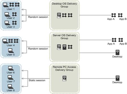
Citrix Provisioning Services
Citrix XenDesktop 7.7 can be deployed with or without Citrix Provisioning Services (PVS). The advantage of using Citrix PVS is that it allows virtual machines to be provisioned and re-provisioned in real-time from a single shared-disk image. In this way administrators can completely eliminate the need to manage and patch individual systems and reduce the number of disk images that they manage, even as the number of machines continues to grow, simultaneously providing the efficiencies of a centralized management with the benefits of distributed processing.
The Provisioning Services solution’s infrastructure is based on software-streaming technology. After installing and configuring Provisioning Services components, a single shared disk image (vDisk) is created from a device’s hard drive by taking a snapshot of the OS and application image, and then storing that image as a vDisk file on the network. A device that is used during the vDisk creation process is the Master target device. Devices or virtual machines that use the created vDisks are called target devices.
When a target device is turned on, it is set to boot from the network and to communicate with a Provisioning Server. Unlike thin-client technology, processing takes place on the target device (Step 1).
Figure 17 Citrix Provisioning Services Functionality
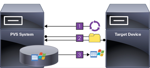
The target device downloads the boot file from a Provisioning Server (Step 2) and boots. Based on the boot configuration settings, the appropriate vDisk is mounted on the Provisioning Server (Step 3). The vDisk software is then streamed to the target device as needed, appearing as a regular hard drive to the system.
Instead of immediately pulling all the vDisk contents down to the target device (as with traditional imaging solutions), the data is brought across the network in real-time as needed. This approach allows a target device to get a completely new operating system and set of software in the time it takes to reboot. This approach dramatically decreases the amount of network bandwidth required and making it possible to support a larger number of target devices on a network without impacting performance
Citrix PVS can create desktops as Pooled or Private:
§ Pooled Desktop: A pooled virtual desktop uses Citrix PVS to stream a standard desktop image to multiple desktop instances upon boot.
§ Private Desktop: A private desktop is a single desktop assigned to one distinct user.
The alternative to Citrix Provisioning Services for pooled desktop deployments is Citrix Machine Creation Services (MCS), which is integrated with the XenDesktop Studio console.
Locating the PVS Write Cache
When considering a PVS deployment, there are some design decisions that need to be made regarding the write cache for the target devices that leverage provisioning services. The write cache is a cache of all data that the target device has written. If data is written to the PVS vDisk in a caching mode, the data is not written back to the base vDisk. Instead it is written to a write cache file in one of the following locations:
§ Cache on device hard drive. Write cache exists as a file in NTFS format, located on the target-device’s hard drive. This option frees up the Provisioning Server since it does not have to process write requests and does not have the finite limitation of RAM.
§ Cache on device hard drive persisted. (Experimental Phase) This is the same as “Cache on device hard drive”, except that the cache persists. At this time, this method is an experimental feature only, and is only supported for NT6.1 or later (Windows 7 and Windows 2008 R2 and later). This method also requires a different bootstrap.
§ Cache in device RAM. Write cache can exist as a temporary file in the target device’s RAM. This provides the fastest method of disk access since memory access is always faster than disk access.
§ Cache in device RAM with overflow on hard disk. This method uses VHDX differencing format and is only available for Windows 7 and Server 2008 R2 and later. When RAM is zero, the target device write cache is only written to the local disk. When RAM is not zero, the target device write cache is written to RAM first. When RAM is full, the least recently used block of data is written to the local differencing disk to accommodate newer data on RAM. The amount of RAM specified is the non-paged kernel memory that the target device will consume.
§ Cache on a server. Write cache can exist as a temporary file on a Provisioning Server. In this configuration, all writes are handled by the Provisioning Server, which can increase disk I/O and network traffic. For additional security, the Provisioning Server can be configured to encrypt write cache files. Since the write-cache file persists on the hard drive between reboots, encrypted data provides data protection in the event a hard drive is stolen.
§ Cache on server persisted. This cache option allows for the saved changes between reboots. Using this option, a rebooted target device is able to retrieve changes made from previous sessions that differ from the read only vDisk image. If a vDisk is set to this method of caching, each target device that accesses the vDisk automatically has a device-specific, writable disk file created. Any changes made to the vDisk image are written to that file, which is not automatically deleted upon shutdown.
![]() In this CVD, Provisioning Server 7.7 was used to manage Pooled/Non-Persistent VDI Machines and XenApp RDS Machines with “Cache in device RAM with overflow on hard disk” for each virtual machine. This design enables good scalability to many thousands of desktops. Provisioning Server 7.7 was used for Active Directory machine account creation and management as well as for streaming the shared disk to the hypervisor hosts.
In this CVD, Provisioning Server 7.7 was used to manage Pooled/Non-Persistent VDI Machines and XenApp RDS Machines with “Cache in device RAM with overflow on hard disk” for each virtual machine. This design enables good scalability to many thousands of desktops. Provisioning Server 7.7 was used for Active Directory machine account creation and management as well as for streaming the shared disk to the hypervisor hosts.
Example XenDesktop Deployments
Two examples of typical XenDesktop deployments are the following:
§ A distributed components configuration
§ A multiple site configuration
Since XenApp and XenDesktop 7.7 are based on a unified architecture, combined they can deliver a combination of Hosted Shared Desktops (HSDs, using a Server OS machine) and Hosted Virtual Desktops (HVDs, using a Desktop OS).
Distributed Components Configuration
You can distribute the components of your deployment among a greater number of servers, or provide greater scalability and failover by increasing the number of controllers in your site. You can install management consoles on separate computers to manage the deployment remotely. A distributed deployment is necessary for an infrastructure based on remote access through NetScaler Gateway (formerly called Access Gateway).
Figure 18 shows an example of a distributed components configuration. A simplified version of this configuration is often deployed for an initial proof-of-concept (POC) deployment. The CVD described in this document deploys Citrix XenDesktop in a configuration that resembles this distributed components configuration shown.
Figure 18 Example of a Distributed Components Configuration
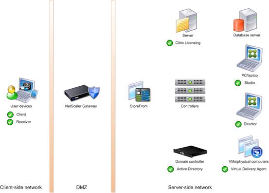
Multiple Site Configuration
If you have multiple regional sites, you can use Citrix NetScaler to direct user connections to the most appropriate site and StoreFront to deliver desktops and applications to users.
In Figure 19, depicting multiple sites, a site was created in two data centers. Having two sites globally, rather than just one, minimizes the amount of unnecessary WAN traffic. Two Cisco blade servers host the required infrastructure services (AD, DNS, DHCP, Profile, SQL, Citrix XenDesktop management, and web servers).
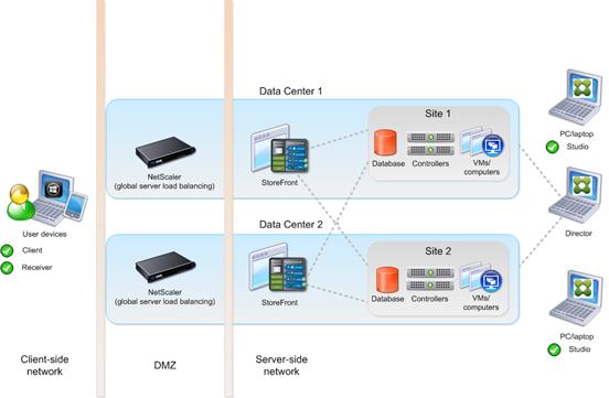
You can use StoreFront to aggregate resources from multiple sites to provide users with a single point of access with NetScaler. A separate Studio console is required to manage each site; sites cannot be managed as a single entity. You can use Director to support users across sites.
Citrix NetScaler accelerates application performance, load balances servers, increases security, and optimizes the user experience. In this example, two NetScalers are used to provide a high availability configuration. The NetScalers are configured for Global Server Load Balancing and positioned in the DMZ to provide a multi-site, fault-tolerant solution.
Designing a XenDesktop Environment for a Mixed Workload
With Citrix XenDesktop 7.7, the method you choose to provide applications or desktops to users depends on the types of applications and desktops you are hosting and available system resources, as well as the types of users and user experience you want to provide.
| Server OS machines | You want: Inexpensive server-based delivery to minimize the cost of delivering applications to a large number of users, while providing a secure, high-definition user experience. Your users: Perform well-defined tasks and do not require personalization or offline access to applications. Users may include task workers such as call center operators and retail workers, or users that share workstations. Application types: Any application. |
| Desktop OS machines
| You want: A client-based application delivery solution that is secure, provides centralized management, and supports a large number of users per host server (or hypervisor), while providing users with applications that display seamlessly in high-definition. Your users: Are internal, external contractors, third-party collaborators, and other provisional team members. Users do not require off-line access to hosted applications. Application types: Applications that might not work well with other applications or might interact with the operating system, such as .NET framework. These types of applications are ideal for hosting on virtual machines. Applications running on older operating systems such as Windows XP or Windows Vista, and older architectures, such as 32-bit or 16-bit. By isolating each application on its own virtual machine, if one machine fails, it does not impact other users. |
| Remote PC Access
| You want: Employees with secure remote access to a physical computer without using a VPN. For example, the user may be accessing their physical desktop PC from home or through a public WIFI hotspot. Depending upon the location, you may want to restrict the ability to print or copy and paste outside of the desktop. This method enables BYO device support without migrating desktop images into the datacenter. Your users: Employees or contractors that have the option to work from home, but need access to specific software or data on their corporate desktops to perform their jobs remotely. Host: The same as Desktop OS machines. Application types: Applications that are delivered from an office computer and display seamlessly in high definition on the remote user's device. |
For the Cisco Validated Design described in this document, a mix of Hosted Shared Desktops (HSDs) using RDS-based Server OS machines and Hosted Virtual Desktops (HVDs) using VDI-based Desktop OS machines were configured and tested. The mix consisted of a combination of both use cases. The following sections discuss design decisions relative to the Citrix XenDesktop deployment, including the CVD test environment.
Storage Architecture Design
Virtual desktop solutions deliver OS, user, and corporate-application management and user profile and data management.
NetApp recommends implementing virtual layering technologies to separate the various components of a desktop, including the base OS image, user profiles and settings, corporate apps, user-installed apps, and user data, into manageable entities called layers. Layers create the lowest storage costs per desktop because you do not need to size storage for peak. For example, Snapshot-based backup and recovery can be applied to the different layers of the desktop to improve storage efficiency.
The key benefits of virtual desktop layering are as follows:
§ Ease of virtual desktop infrastructure (VDI) image management. Individual desktops no longer need to be patched or updated individually. This feature results in cost savings because you do not need to size the storage array for write I/O storms.
§ Efficient data management. Separating the different desktop components into layers allows for the application of intelligent data management policies, such as deduplication, NetApp Snapshot backups, and so on, on different layers as required. For example, you can enable deduplication on storage volumes that host Citrix personal vDisks and user data.
§ Ease of application rollout and updates. Layering improves the roll out of new applications and updates to existing applications.
§ Improved end-user experience. Layering allows users to install applications and permits the persistence of these applications during updates to the desktop OS or applications.
High-Level Architecture Design
This section outlines the recommended storage architecture for deploying a mix of various XenDesktop FlexCast delivery models on the same NetApp clustered Data ONTAP storage array. These models include hosted VDI, hosted-shared desktops, and intelligent VDI layering, such as profile management and user data management.
For hosted and shared desktops and the hosted VDI, the following recommendations are best practices for the OS vDisk, the write cache disk, profile management, user data management, and application virtualization:
§ Provisioning Services (PVS) vDisk. CIFS/SMB 3 is used to host the PVS vDisk. CIFS/SMB 3 allows the same vDisk to be shared among multiple PVS servers while still maintaining resilience during storage node failover. This process results in significant operational savings and architecture simplicity. SMB3 is available in Windows Server 2012 or higher and provides persistent handles. SMB3 persistent handles prevents the PVS server from crashing during a storage node failover. Therefore, Windows 2012 is the required OS for a PVS server to ensure a stable PVS implementation.
§ PVS write cache file. For simplicity and scalability, the PVS write cache file is hosted on NFS storage repositories. Deduplication should not be enabled on this volume, because the rate of change is too high. The PVS write cache file should be set for thin provisioning at the storage layer.
§ Profile management. To make sure that user profiles and settings are preserved, you should leverage the profile management software Citrix UPM to redirect the user profiles to the CIFS home directories.
§ User data management. NetApp recommends hosting user data on CIFS home directories to preserve data upon VM reboot or redeploy.
§ Monitoring and management. NetApp recommends using OnCommand Balance and Citrix Desktop Director to provide end-to-end monitoring and management of the solution.
NetApp Architecture Design Best Practice Guidelines
The following section is a compilation of NetApp best practices that have been discussed previously in this document.
Storage Configuration
§ Use System Manager to create the SVM.
§ Verify that you are using the latest release of clustered Data ONTAP.
§ Segregate the SVMs by tenant, solution, or apps administrator or alternatively by protocol.
§ Do not configure too many SVMs. Because volume move is isolated within an SVM, configuring too many SVMs has the potential to limit the use of volume move or copy. Configuring too many SVMs can also make administration more complex.
§ Create load-sharing mirrors for all of the SVM root volumes.
§ Make sure to use advance data partitioning to create the root aggregates.
§ Create one data aggregate per controller.
§ Create volumes in multiples of four volumes per storage node (4, 8, 12, 16 and so on).
§ Create a minimum of four volumes on each storage controller (node) for Remote Desktop Services (RDS) in groups of four volumes per storage node.
§ Create a minimum of four volumes on each storage controller (node) for PVS nonpersistent VDI in groups of four volumes per storage node.
§ Create a minimum of four volumes on each storage controller (node) for Machine Creation Services (MCS) persistent VDI in groups of four volumes per storage node.
§ Make sure that inline deduplication is configured on storage volumes that benefit from deduplication.
§ Make sure that the deduplication policy Inline Only is set on all volumes.
§ Set both the Inline Compression option and the Inline Deduplication option to True for all VDI, Infrastructure, and CIFS volumes.
§ Set both the Inline Compression option and the Inline Deduplication option to False for all swap volumes and volumes with high rate of changes (for example, database logs).
§ If you are using a switchless storage cluster, make sure that the Switchless option is set.
§ Create load-sharing mirrors for all SVM root volumes.
§ Create a minimum of one LIF per volume (storage repository) if possible.
§ Create LIF failover groups and assigned them to LIFs.
§ NAS LIFs are the only LIFs that migrate. Therefore, make sure that Asymmetric Logical Unit Access (ALUA) is configured and working for block protocol LIFs.
§ Assign the same port on each clustered storage node to the same LIF.
§ Use the latest release of clustered Data ONTAP.
§ Use the latest release of shelf firmware and disk firmware.
Networking Configuration for Storage
§ Switch ports connected to the NetApp storage controllers must be set to edge ports to turn spanning tree off. Also, make sure that portfast is enabled.
§ Set flow control to None on the switch, storage controller, and XenServer ports.
§ Make sure that Suspend-Individual is set to No on the switch.
§ Use jumbo frames on the NFS data network.
§ Use the Link Aggregation Control Protocol (LACP) or the virtual port channel (VPC) for port teaming.
§ Make sure that the load-balancing method is set to Port.
§ The NFS data network should be nonroutable.
§ Segregate the CIFS network and NFS data network on different ports or interface groups to eliminate the possibility of maximum transmission unit (MTU) mismatch errors.
§ Make sure that the load-balancing method is set to Port.
VMware vSphere 6.0 Hypervisor Considerations for Storage
§ Use FCoE or iSCSI for the boot LUNs and configure Boot from SAN.
§ Separate iSCSI paths with VLANs.
§ Use Virtual Storage Console (VSC) for creating datastores.
§ Use NFS volumes for the datastores.
§ If you are using NFS 4.1, separate NFS dual paths with VLANs.
§ Create the thick eager-zero for your VMDK.
§ Use iSCSI for the boot LUNs and configure Boot from SAN.
Citrix Considerations for Storage
§ Use NetApp VSC to provision Citrix persistent desktops.
§ Use the VSC for resizing or applying deduplication to the storage datastores.
§ Use NFS volumes for the storage datastores.
§ Do not configure Always-On Deduplication with In-Line Deduplication on the volume.
§ Use In-Line Deduplication on the infrastructure volumes.
§ Thin provision the write cache infrastructure volumes at the storage layer.
§ Use SMB3 for the PVS CIFS share with the NetApp continuous share feature.
§ Use a profile manager for profiles and CIFS. NetApp recommends Citrix UPM.
§ Use redirected folders for the home directories on the CIFS shares.
§ Do not locate the redirected folders in the profiles folder. This will cause login performance issues.
Monitoring, Management, and Sizing
§ NetApp recommends UCS Director for servers, storage, and switch infrastructure.
§ NetApp recommends OnCommand Insight to monitor VDI I/O from guests to storage.
§ Have a NetApp sales engineer or a NetApp partner use the NetApp SPM tool to size the virtual desktop solution. When sizing CIFS, NetApp recommends sizing with a heavy user workload. We assumed 80% concurrency and 10GB per user for home directory space with 35% deduplication space savings. Each VM used 2GB of RAM. PVS write cache is sized at 5GB per desktop for nonpersistent and pooled desktops and 2GB for persistent desktops with personal vDisk.
Storage Architecture Design Layout
The storage components for this reference architecture were composed of two AFF8080EX-A nodes with 48 800GB SSD drives. We used clustered Data ONTAP 8.3.2.
To support the differing security, backup, performance, and data sharing needs of your users, group the physical data storage resources on your storage system into one or more aggregates. You can design and configure your aggregates to provide the appropriate level of performance and redundancy for your storage requirements.
Each aggregate has its own RAID configuration, plex structure, and set of assigned disks or array LUNs. The aggregate provides storage, based on its configuration, to its associated NetApp FlexVol® volumes or Infinite Volumes. Aggregates have the following characteristics:
§ They can be composed of disks or array LUNs.
§ They can be mirrored or unmirrored.
§ If they are composed of disks, they can be single-tier (composed of only HDDs or only SSDs), or they can be Flash Pools, which include both of those storage types in two separate tiers.
The cluster administrator can assign one or more aggregates to an SVM. which means that only those aggregates can contain volumes for that SVM.
Unless you are using SyncMirror, all of your aggregates are unmirrored. Unmirrored aggregates have only one plex (copy of their data), which contains all of the RAID groups belonging to that aggregate. Mirrored aggregates have two plexes (copies of their data) that use the SyncMirror functionality to duplicate the data to provide redundancy.
A Flash Pool aggregate combines SSDs and HDDs to provide performance and capacity, respectively. This combination creates a high performance aggregate more economically than an SSD-only aggregate. The SSDs provide a high-performance cache for the active data set of the data volumes provisioned on the Flash Pool aggregate. Random read operations and repetitive random write operations are offloaded to improve response times and overall throughput for disk I/O-bound data access operations. Performance is not significantly increased for predominately sequential workloads.
For information about best practices for working with aggregates, see Technical Report 3437: Storage Subsystem Resiliency Guide.
Table 2 contains all aggregate configuration information.
Table 2 Aggregate Configuration
| Aggregate Name | Owner Node Name | State | RAID Status | RAID Type |
| aff_aggr0_root_node01 | aff-cluster-01-01 | online | normal | raid_dp |
| aff_aggr0_root_node02 | aff-cluster-01-02 | online | normal | raid_dp |
| aff_aggr1_data_node01 | aff-cluster-01-01 | online | normal | raid_dp |
| aff_aggr1_data_node02 | aff-cluster-01-02 | online | normal | raid_dp |
| Disk Count (By Type) | RG Size (HDD / SSD) | HA Policy | Has Mroot | Mirrored | Size Nominal |
| 22@800GB_SSD (Shared) | 23 | cfo | True | False | 368.42 GB |
| 22@800GB_SSD (Shared) | 23 | cfo | True | False | 368.42 GB |
| 23@800GB_SSD (Shared) | 23 | sfo | False | False | 13.35 TB |
| 23@800GB_SSD (Shared) | 23 | sfo | False | False | 13.35 TB |
Volumes are data containers that allow you to partition and manage your data. Understanding the types of volumes and their associated capabilities enables you to design your storage architecture for maximum storage efficiency and ease of administration. Volumes are the highest-level logical storage object. Unlike aggregates, which are composed of physical storage resources, volumes are completely logical objects.
Clustered Data ONTAP provides two types of volumes: FlexVol volumes and Infinite Volumes. There are also volume variations, such as FlexClone volumes, NetApp FlexCache® volumes, data protection mirrors, extended data protection mirrors and load-sharing mirrors. Not all volume variations are supported for both types of volumes. Compression and deduplication, the Data ONTAP efficiency capabilities, are supported for all types of volumes.
Volumes contain file systems in a NAS environment and LUNs in a SAN environment. Also, volumes are always associated with one SVM. The SVM is a virtual management entity, or server, that consolidates various cluster resources into a single manageable unit. When you create a volume, you specify the SVM that it is associated with. The type of the volume (FlexVol volume or Infinite Volume) and its language are determined by immutable SVM attributes.
Volumes depend on their associated aggregates for their physical storage; they are not directly associated with any physical storage objects, such as disks or RAID groups. If the cluster administrator has assigned specific aggregates to an SVM, then only those aggregates can be used to provide storage to the volumes associated with that SVM. This impacts volume creation, and also copying and moving FlexVol volumes between aggregates.
Root Volume Configuration
A node's root volume is a FlexVol volume that is installed at the factory and reserved for system files, log files, and core files. The directory name is /mroot, which is accessible only through the systemshell with guidance from technical support.
Every SVM has a root volume that contains the paths where the data volumes are junctioned into the namespace. Data access for NAS clients is dependent on the root volume namespace, and SAN data access for SAN clients is not dependent on the root volume namespace.
The root volume serves as the entry point to the namespace provided by that SVM. The root volume of an SVM is a FlexVol volume that resides at the top level of the namespace hierarchy. The root volume contains the directories that are used as mount points (paths where data volumes are junctioned into the namespace).
Table 3 lists the node and SVM root volumes configuration.
Table 3 Root Volume Configuration
| Cluster Name | SVM Name | Volume Name | Containing Aggregate | Root Type | State | Snapshot Policy | Export Policy | Security Style | Size Nominal |
| aff-cluster-01 | aff-cluster-01-01 | vol0 | aff_aggr0_root_node01 | Node | online |
|
|
| 348.62 GB |
| aff-cluster-01 | aff-cluster-01-02 | vol0 | aff_aggr0_root_node02 | Node | online |
|
|
| 348.62 GB |
| aff-cluster-01 | San_Boot | San_Boot_root | aff_aggr1_data_node01 | Vserver (RW) | online | default | default | UNIX | 1.00 GB |
| aff-cluster-01 | VDI | VDI_root | aff_aggr1_data_node02 | Vserver (RW) | online | default | default | UNIX | 1.00 GB |
FlexVol Configuration
A FlexVol volume is a data container associated with a NetApp Storage Virtual Machine (SVM). A FlexVol volume accesses storage from a single associated aggregate that it might share with other FlexVol volumes or Infinite Volumes. A FlexVol volume can be used to contain files in a NAS environment or LUNs in a SAN environment. Table 4 lists the configuration of FlexVol volumes.
Table 4 FlexVol Volume Configuration
| Cluster Name | SVM Name | Volume Name | Containing Aggregate | Type | Snapshot Policy | Export Policy | Security Style | Size Nominal |
| aff-cluster-01 | San_Boot | San_Boot01 | aff_aggr1_data_node01 | RW | none | default | UNIX | 300.00 GB |
| aff-cluster-01 | San_Boot | San_Boot02 | aff_aggr1_data_node02 | RW | none | default | UNIX | 300.00 GB |
| aff-cluster-01 | VDI | CIFS_HomeDir01 | aff_aggr1_data_node01 | RW | default | CIFS | NTFS | 200.00 GB |
| aff-cluster-01 | VDI | CIFS_HomeDir02 | aff_aggr1_data_node02 | RW | default | CIFS | NTFS | 200.00 GB |
| aff-cluster-01 | VDI | CIFS_HomeDir03 | aff_aggr1_data_node01 | RW | default | CIFS | NTFS | 200.00 GB |
| aff-cluster-01 | VDI | CIFS_HomeDir04 | aff_aggr1_data_node02 | RW | default | CIFS | NTFS | 200.00 GB |
| aff-cluster-01 | VDI | CIFS_HomeDir05 | aff_aggr1_data_node01 | RW | default | CIFS | NTFS | 200.00 GB |
| aff-cluster-01 | VDI | CIFS_HomeDir06 | aff_aggr1_data_node02 | RW | default | CIFS | NTFS | 200.00 GB |
| aff-cluster-01 | VDI | CIFS_HomeDir07 | aff_aggr1_data_node01 | RW | default | CIFS | NTFS | 200.00 GB |
| aff-cluster-01 | VDI | CIFS_HomeDir08 | aff_aggr1_data_node02 | RW | default | CIFS | NTFS | 200.00 GB |
| aff-cluster-01 | VDI | CIFS_HomeDir09 | aff_aggr1_data_node01 | RW | default | CIFS | NTFS | 200.00 GB |
| aff-cluster-01 | VDI | CIFS_HomeDir10 | aff_aggr1_data_node02 | RW | default | CIFS | NTFS | 200.00 GB |
| aff-cluster-01 | VDI | CIFS_PVS_vDisk01 | aff_aggr1_data_node02 | RW | default | CIFS | NTFS | 250.00 GB |
| aff-cluster-01 | VDI | CIFS_RDSH01 | aff_aggr1_data_node01 | RW | default | CIFS | NTFS | 200.00 GB |
| aff-cluster-01 | VDI | CIFS_VDI01 | aff_aggr1_data_node02 | RW | default | CIFS | NTFS | 200.00 GB |
| aff-cluster-01 | VDI | Infra01 | aff_aggr1_data_node01 | RW | none | NFS | UNIX | 1.95 TB |
| aff-cluster-01 | VDI | MCS_PERS01 | aff_aggr1_data_node01 | RW | default | NFS | UNIX | 500.00 GB |
| aff-cluster-01 | VDI | MCS_PERS02 | aff_aggr1_data_node02 | RW | default | NFS | UNIX | 500.00 GB |
| aff-cluster-01 | VDI | MCS_PERS03 | aff_aggr1_data_node01 | RW | default | NFS | UNIX | 500.00 GB |
| aff-cluster-01 | VDI | MCS_PERS04 | aff_aggr1_data_node02 | RW | default | NFS | UNIX | 500.00 GB |
| aff-cluster-01 | VDI | MCS_PERS05 | aff_aggr1_data_node01 | RW | default | NFS | UNIX | 500.00 GB |
| aff-cluster-01 | VDI | MCS_PERS06 | aff_aggr1_data_node02 | RW | default | NFS | UNIX | 500.00 GB |
| aff-cluster-01 | VDI | MCS_PERS07 | aff_aggr1_data_node01 | RW | default | NFS | UNIX | 500.00 GB |
| aff-cluster-01 | VDI | MCS_PERS08 | aff_aggr1_data_node02 | RW | default | NFS | UNIX | 500.00 GB |
| aff-cluster-01 | VDI | PVSWC_NON_PERS01 | aff_aggr1_data_node01 | RW | default | NFS | UNIX | 500.00 GB |
| aff-cluster-01 | VDI | PVSWC_NON_PERS02 | aff_aggr1_data_node02 | RW | default | NFS | UNIX | 500.00 GB |
| aff-cluster-01 | VDI | PVSWC_NON_PERS03 | aff_aggr1_data_node01 | RW | default | NFS | UNIX | 500.00 GB |
| aff-cluster-01 | VDI | PVSWC_NON_PERS04 | aff_aggr1_data_node02 | RW | default | NFS | UNIX | 500.00 GB |
| aff-cluster-01 | VDI | PVSWC_NON_PERS05 | aff_aggr1_data_node01 | RW | default | NFS | UNIX | 500.00 GB |
| aff-cluster-01 | VDI | PVSWC_NON_PERS06 | aff_aggr1_data_node02 | RW | default | NFS | UNIX | 500.00 GB |
| aff-cluster-01 | VDI | PVSWC_NON_PERS07 | aff_aggr1_data_node01 | RW | default | NFS | UNIX | 500.00 GB |
| aff-cluster-01 | VDI | PVSWC_NON_PERS08 | aff_aggr1_data_node02 | RW | default | NFS | UNIX | 500.00 GB |
| aff-cluster-01 | VDI | PVSWC_RDSH01 | aff_aggr1_data_node01 | RW | default | NFS | UNIX | 200.00 GB |
| aff-cluster-01 | VDI | PVSWC_RDSH02 | aff_aggr1_data_node02 | RW | default | NFS | UNIX | 200.00 GB |
| aff-cluster-01 | VDI | PVSWC_RDSH03 | aff_aggr1_data_node01 | RW | default | NFS | UNIX | 200.00 GB |
| aff-cluster-01 | VDI | PVSWC_RDSH04 | aff_aggr1_data_node02 | RW | default | NFS | UNIX | 200.00 GB |
| aff-cluster-01 | VDI | PVSWC_RDSH05 | aff_aggr1_data_node01 | RW | default | NFS | UNIX | 200.00 GB |
| aff-cluster-01 | VDI | PVSWC_RDSH06 | aff_aggr1_data_node02 | RW | default | NFS | UNIX | 200.00 GB |
| aff-cluster-01 | VDI | PVSWC_RDSH07 | aff_aggr1_data_node01 | RW | default | NFS | UNIX | 200.00 GB |
| aff-cluster-01 | VDI | PVSWC_RDSH08 | aff_aggr1_data_node02 | RW | default | NFS | UNIX | 200.00 GB |
| aff-cluster-01 | VDI | VM_Infra01 | aff_aggr1_data_node01 | RW | default | NFS | UNIX | 2.00 TB |
| aff-cluster-01 | VDI | VM_Swap01 | aff_aggr1_data_node02 | RW | default | NFS | UNIX | 100.00 GB |
| aff-cluster-01 | VDI | VMSWP | aff_aggr1_data_node02 | RW | none | NFS | UNIX | 100.00 GB |
We created 47 volumes to support the individual software component tests (RDS, PVS nonpersistent, and MCS persistent), which we call cluster testing. These volumes also supported the full-scale testing of all 5,000 users in a mixed workload environment.
The mixed workload environment consisted of 2,600 RDS (hosted shared desktop) desktop users, 1,200 PVS nonpersistent desktop users, and 1,200 MCS persistent desktop users. Although the persistent desktop users were managed by the Citrix MCS broker, they were provisioned with NetApp VSC. Later in this document we discuss in detail the benefits of using NetApp VSC to provision physical desktops. Also, note that we adhered to four volumes per controller per software component.
Storage Cluster Configuration
Cluster Details
You can group HA pairs of nodes together to form a scalable cluster. Creating a cluster enables the nodes to pool their resources and distribute work across the cluster while presenting administrators with a single entity to manage. Clustering also enables continuous service to end users if individual nodes go offline.
A cluster can contain up to 24 nodes (or up to 10 nodes if it contains an SVM with an Infinite Volume) for NAS-based clusters and up to 8 nodes for SAN based clusters (as of Data ONTAP 8.2). Each node in the cluster can view and manage the same volumes as any other node in the cluster. The total file-system namespace, which comprises all of the volumes and their resultant paths, spans the cluster.
If you have a two-node cluster, you must configure cluster HA. For more information, see the Clustered Data ONTAP High-Availability Configuration Guide.
The nodes in a cluster communicate over a dedicated, physically isolated, dual-fabric, secure Ethernet network. The cluster LIFs on each node in the cluster must be on the same subnet. For information about network management for cluster and nodes, see the Clustered Data ONTAP Network Management Guide. For information about setting up a cluster or joining a node to the cluster, see the Clustered Data ONTAP Software Setup Guide.
Table 5 shows the cluster details.
| Cluster Name | Data ONTAP Version | Node Count | Data SVM Count | Cluster Raw Capacity |
| aff-cluster-01 | 8.3.2 | 2 | 2 | 34.20 TB |
Node Details
A node is a controller in a cluster that is connected to other nodes in the cluster over a cluster network. It is also connected to the disk shelves that provide physical storage for the Data ONTAP system or to third-party storage arrays that provide array LUNs for Data ONTAP use.
Table 6 shows the node details.
| Cluster Name | Node Name | System Model | Serial Number | HA Partner Node Name | Data ONTAP Version |
| aff-cluster-01 | aff-cluster-01-01 | AFF8080 | 721544000374 | aff-cluster-01-02 | 8.3.2 |
| aff-cluster-01 | aff-cluster-01-02 | AFF8080 | 721544000373 | aff-cluster-01-01 | 8.3.2 |
Storage Configuration
Table 7 shows the storage configuration for each node.
| Node Name | Shelf Connectivity | ACP Connectivity | Cluster HA Configured | SFO Enabled | Takeover Possible |
| aff-cluster-01-01 | Multi-Path HA | Full Connectivity | True | True | True |
| aff-cluster-01-02 | Multi-Path HA | Full Connectivity | True | True | True |
Storage Details
Table 8 shows the storage details for each HA pair.
| Node Names | Shelf Count | Disk Count | Disk Capacity | Raw Capacity |
| aff-cluster-01-01 aff-cluster-01-02 | DS2246: 2 | SSD: 47 | SSD: 34.20 TB | 34.20 TB |
Raw capacity is not the same as usable capacity.
Shelf Details
Table 9 shows the shelf details for each HA pair.
| Cluster Name | Node Names | Shelf ID | Shelf State | Shelf Model | Shelf Type | Drive Slot Count |
| aff-cluster-01 | aff-cluster-01-01 aff-cluster-01-02 | 10 | online | DS2246 | IOM6 | 24 |
| aff-cluster-01 | aff-cluster-01-01 aff-cluster-01-02 | 11 | online | DS2246 | IOM6 | 24 |
Drive Allocation Details
Table 10 shows the drive allocation details for each node.
Table 10 Drive Allocation Details
| Node Name | Total Disk Count | Allocated Disk Count | Disk Type | Raw Capacity | Spare Disk Count |
| – | 1 | 0 | – | 0 | 0 |
| aff-cluster-01-01 | 23 | 23 | 800GB_SSD | 16.74 TB | 0 |
| aff-cluster-01-02 | 24 | 24 | 800GB_SSD | 17.47 TB | 0 |
Raw capacity is not the same as usable capacity.
Adapter Card Details
Table 11 shows the adapter cards present in each node.
| Node Name | System Model | Adapter Card |
| aff-cluster-01-01 | AFF8080 | slot 1: X1117A: Intel Dual 10G IX1-SFP+ NIC slot 3: X2065A: PMC PM8001; PCI-E quad-port SAS (PM8003) slot 4: X1117A: Intel Dual 10G IX1-SFP+ NIC |
| aff-cluster-01-02 | AFF8080 | slot 1: X1117A: Intel Dual 10G IX1-SFP+ NIC slot 3: X2065A: PMC PM8001; PCI-E quad-port SAS (PM8003) slot 4: X1117A: Intel Dual 10G IX1-SFP+ NIC |
Remote Management Devices
You can manage a node remotely by using a remote management device, which can be the SP or the RLM, depending on the platform model. The device stays operational regardless of the operating state of the node.
The RLM is included in the 31xx, 6040, and 6080 platforms. The SP is included in all other platform models.
Table 12 lists the remote management devices.
Table 12 Remote Management Devices
| Cluster Name | Node Name | Type | Status | IP Address | Gateway |
| aff-cluster-01 | aff-cluster-01-01 | SP | online | 10.29.164.75/24 | 10.29.164.1 |
| aff-cluster-01 | aff-cluster-01-02 | SP | online | 10.29.164.76/24 | 10.29.164.1 |
Firmware Details
Table 13 shows the relevant firmware details for each node.
| Node Name | Node Firmware | Shelf Firmware | Drive Firmware | Remote Mgmt Firmware |
| aff-cluster-01-01 | AFF8080: 9.3 | IOM6: A:0181, B:0181 | X447_1625800MCSG: NA03 X447_S1633800AMD: NA01 | SP: 3.1.2 |
| aff-cluster-01-02 | AFF8080: 9.3 | IOM6: A:0181, B:0181 | X447_1625800MCSG: NA03 X447_S1633800AMD: NA01 | SP: 3.1.2 |
Software
Clustered Data ONTAP provides features for network file service, multiprotocol file and block sharing, data storage management, and data organization management, data access management, data migration management, data protection management, and AutoSupport.
AutoSupport
AutoSupport proactively monitors the health of your system and automatically sends email messages to NetApp technical support, your internal support organization, and a support partner. Only the cluster administrator can perform AutoSupport management. The SVM administrator has no access to AutoSupport. AutoSupport is enabled by default when you configure your storage system for the first time.
AutoSupport begins sending messages to technical support 24 hours after AutoSupport is enabled. You can cut short the 24-hour period by upgrading or reverting the system, modifying the AutoSupport configuration, or changing the time of the system to be outside of the 24-hour period.
You can disable AutoSupport at any time, but you should leave it enabled. Enabling AutoSupport can significantly help speed problem determination and resolution should a problem occur on your storage system. By default, the system collects AutoSupport information and stores it locally even if you disable AutoSupport.
Although AutoSupport messages to technical support are enabled by default, you need to set the correct options and have a valid mail host to have messages sent to your internal support organization.
For more information about AutoSupport, see the NetApp Support Site.
AutoSupport Settings
Table 14 lists the AutoSupport settings.
| Node Name | Enabled | Support Enabled | Performance Data Enabled | Private Data Removed | Throttle Enabled |
| aff-cluster-01-01 | True | True | True | False | True |
| aff-cluster-01-02 | True | True | True | False | True |
System Time Settings (Clustered Data ONTAP 8.3 or Later)
Problems can occur when the cluster time is inaccurate. Although you can manually set the time zone, date, and time on the cluster, you should configure the Network Time Protocol (NTP) servers to synchronize the cluster time. NTP is always enabled. However, configuration is still required for the cluster to synchronize with an external time source.
Table 15 lists the system time settings for Data ONTAP 8.3 or later.
Table 15 System Time Settings for Data ONTAP 8.3
| Cluster Name | Server | Version | Preferred | Public Default |
| aff-cluster-01 | 10.29.164.66 | auto | False | False |
Cluster Host-Name Resolution
Clustered Data ONTAP supports two methods for host-name resolution: DNS and hosts table. Cluster administrators can configure DNS and hosts file naming services for host-name lookup in the admin SVM.
Cluster DNS Settings
Table 16 lists the cluster DNS settings.
| Cluster Name | State | Domain Names | Servers |
| aff-cluster-01 | enabled | dvpod2.local | 10.10.61.30 10.10.61.31 |
Clustered ONTAP Configuration
Storage Virtual Machines
An SVM is a secure virtual storage server that contains data volumes and one or more LIFs through which it serves data to the clients. An SVM appears as a single dedicated server to the clients. Each SVM has a separate administrator authentication domain and can be managed independently by its SVM administrator.
In a cluster, an SVM facilitates data access. A cluster must have at least one SVM to serve data. SVMs use the storage and network resources of the cluster. However, the volumes and LIFs are exclusive to the SVM. Multiple SVMs can coexist in a single cluster without being bound to any node in a cluster. However, they are bound to the physical cluster on which they exist.
In Data ONTAP 8.1.1, an SVM can either contain one or more FlexVol volumes, or a single Infinite Volume. A cluster can either have one or more SVMs with FlexVol volumes or one SVM with an Infinite Volume.
SVM Configuration
Table 17 lists the SVM configuration.
| Cluster Name | SVM Name | Type | Subtype | State | Allowed Protocols | Name Server Switch | Name Mapping Switch | Comment |
| aff-cluster-01 | San_Boot | data | default | running | iscsi | file | file |
|
| aff-cluster-01 | VDI | data | default | running | nfs, cifs | file | file |
|
SVM Storage Configuration
Table 18 lists the SVM storage configuration.
Table 18 SVM Storage Configuration
| Cluster Name | SVM Name | Root Volume Security Style | Language | Root Volume | Root Aggregate | Aggregate List |
| aff-cluster-01 | San_Boot | UNIX | en_us | San_Boot_root | aff_aggr1_data_node01 |
|
| aff-cluster-01 | VDI | UNIX | en_us | VDI_root | aff_aggr1_data_node02 |
|
SVM Default Policies
Table 19 lists the SVM default policy settings.
| Cluster Name | SVM Name | Snapshot Policy | Quota Policy | Antivirus On-Access Policy | QOS Policy Group |
| aff-cluster-01 | San_Boot | default | default | default |
|
| aff-cluster-01 | VDI | default | default | default |
|
SVM Host-Name Resolution
A cluster administrator or an SVM administrator can configure DNS for host-name lookup in an SVM.
Starting with Data ONTAP 8.1, each SVM has its own DNS configuration. Each SVM communicates with its DNS server in the SVM's context, which includes the SVM's LIF and routing tables. Client requests are authenticated and authorized by using the specific SVM network configuration. DNS configuration is mandatory when CIFS is used for data access.
SVM DNS Settings
Table 20 lists the SVM DNS settings.
| Cluster Name | SVM Name | DNS State | Domain Names | DNS Servers |
| aff-cluster-01 | San_Boot | enabled | dvpod2.local | 10.10.61.30 10.10.61.31 |
| aff-cluster-01 | VDI | enabled | dvpod2.local | 10.10.61.30 10.10.61.31 |
SVM Administrative Users
An SVM administrator can administer an SVM and its resources, such as volumes, protocols, and services, depending on the capabilities assigned by the cluster administrator.
Table 21 lists the SVM administrative users.
Table 21 SVM Administrative Users
| Cluster Name | SVM Name | Username | Application | Authentication Method | Role Name |
| aff-cluster-01 | San_Boot | vsadmin | ontapi | password | vsadmin |
| aff-cluster-01 | San_Boot | vsadmin | ssh | password | vsadmin |
| aff-cluster-01 | VDI | vsadmin | ontapi | password | vsadmin |
| aff-cluster-01 | VDI | vsadmin | ssh | password | vsadmin |
SVM Name Services
Data ONTAP controls access to files according to the authentication-based and file-based restrictions that you specify. To properly manage file access control, Data ONTAP must communicate with external services such as NIS, LDAP and Active Directory servers. Configuring a storage system for file access using CIFS or NFS requires setting up the appropriate services depending on your environment.
Communication with external services usually occurs over the data LIF of the SVM. In some situations, communication over the data LIF might fail or must be made on a node that does not host data LIFs for the SVM. In this case, the storage system attempts to use node and cluster management LIFs instead. For these reasons, you must ensure that the SVM has a data LIF properly configured to reach all required external services. In addition, all management LIFs in the cluster must be able to reach these external services.
LDAP
Data ONTAP supports LDAP for user authentication, file access authorization, user lookup and mapping services between NFS and CIFS. If the SVM is set up to use LDAP as a name service using the -ns-switch ldap option or for name mapping using the -nm-switch ldap option, you should create an LDAP configuration for it. Clustered Data ONTAP supports only the RFC 2307 schema for LDAP authentication of SVM accounts. It does not support any other schemas, such as Active Directory Identity Management for UNIX (AD-IDMU) and Active Directory Services for UNIX (AD-SFU).
Job Schedules
A job is defined as any asynchronous task. Jobs are typically long-running volume operations such as copy, move, and mirror. Jobs are placed into a job queue and run when resources are available. If a job is consuming too many system resources, you can pause or stop it until there is less demand on the system.
Many tasks—for example, volume snapshots and mirror replications—can be configured to run on specified schedules by using one of the system-wide defined job schedules. Schedules that run at specific times are known as cron schedules because of their similarity to UNIX cron schedules.
Table 22 lists the configured job schedules.
| Cluster Name | Schedule Name | Type | Description |
| aff-cluster-01 | 1min | cron | @:00,:01,:02,:03,:04,:05,:06,:07,:08,:09,:10,:11,:12,:13,:14,:15,:16,:17,:18,:19,:20,:21,:22,:23,:24,:25,:26,:27,:28,:29,:30,:31,:32,:33,:34,:35,:36,:37,:38,:39,:40,:41,:42,:43,:44,:45,:46,:47,:48,:50,:51,:52,:53,:54,:55,:56,:57,:58,:59 |
| aff-cluster-01 | 5min | cron | @:00,:05,:10,:15,:20,:25,:30,:35,:40,:45,:50,:55 |
| aff-cluster-01 | 8hour | cron | @2:15,10:15,18:15 |
| aff-cluster-01 | Auto Balance Aggregate Scheduler | interval | Every 1h |
| aff-cluster-01 | daily | cron | @0:10 |
| aff-cluster-01 | hourly | cron | @:05 |
| aff-cluster-01 | RepositoryBalanceMonitorJobSchedule | interval | Every 10m |
| aff-cluster-01 | weekly | cron | Sun@0:15 |
Policies
Clustered Data ONTAP utilizes policies for many configuration items. These policies are created at the cluster level and are then available for use by the SVMs. For example, Snapshot policies are created and then applied to the FlexVol volumes for which they take snapshots. Specific Snapshot configurations are not defined on a per FlexVol volume basis.
Snapshot Policies
You can create a snapshot policy to specify the frequency and maximum number of automatically created Snapshot copies.
Table 23 lists the snapshot policy settings.
| Cluster Name | SVM Name | Policy Name | Enabled | Total Schedules | Schedule Name | Schedule Prefix | Schedule Count |
| aff-cluster-01 | aff-cluster-01 | default | True | 3 | daily hourly weekly | daily hourly weekly | 2 6 2 |
| aff-cluster-01 | aff-cluster-01 | default-1weekly | True | 3 | daily hourly weekly | daily hourly weekly | 2 6 1 |
| aff-cluster-01 | aff-cluster-01 | none | False | 0 |
|
|
|
SnapMirror Policies
A SnapMirror policy is either a cluster-wide or SVM-wide policy that defines the SnapMirror parameters between the source and destination volumes and is applied to SnapMirror relationships. The SVM parameter defines if the policy is applicable to the entire cluster or a specific SVM.
SnapMirror policies are only available starting with clustered Data ONTAP 8.2.
Table 24 lists the SnapMirror policy settings.
| Cluster Name | SVM Name | Policy Name | Policy Type | Policy Owner | Tries Limit | Total Rules | SnapMirror Label | Keep | Preserve | Warn |
| aff-cluster-01 | aff-cluster-01 | DPDefault | async_mirror | cluster_admin | 8 | 1 | sm_created | 1 | False | 0 |
| aff-cluster-01 | aff-cluster-01 | MirrorAllSnapshots | async_mirror | cluster_admin | 8 | 2 | all_source_snapshots sm_created | 1 1 | False False | 0 0 |
| aff-cluster-01 | aff-cluster-01 | MirrorAndVault | mirror_vault | cluster_admin | 8 | 3 | daily sm_created weekly | 7 1 52 | False False False | 0 0 0 |
| aff-cluster-01 | aff-cluster-01 | MirrorLatest | async_mirror | cluster_admin | 8 | 1 | sm_created | 1 | False | 0 |
| aff-cluster-01 | aff-cluster-01 | XDPDefault | vault | cluster_admin | 8 | 2 | daily weekly | 7 52 | False False | 0 0 |
Export Policy Rules
Export policies enable you to restrict access to volumes to clients that match specific IP addresses and specific authentication types. An export policy with export rules must exist on an SVM for clients to access data. Each volume is associated with one export policy. Each export policy is identified by a unique name and a unique numeric ID. A Data ONTAP cluster can contain up to 1,024 export policies.
Export policies consist of individual export rules. An export policy can contain a large number of rules (approximately 4,000). Each rule specifies access permissions to volumes for one or more clients. The clients can be specified by host name, IP address, or netgroup. Rules are processed in the order in which they appear in the export policy. The rule order is dictated by the rule index number.
The rule also specifies the authentication types that are required for both read-only and read/write operations. To have any access to a volume, matching clients must authenticate with the authentication type specified by the read-only rule. To have write access to the volume, matching clients must authenticate with the authentication type specified by the read/write rule.
If a client makes an access request that is not permitted by the applicable export policy, the request fails with a permission-denied message. If a client IP address does not match any rule in the volume's export policy, then access is denied. If an export policy is empty, then all accesses are implicitly denied. Export rules can use host entries from a netgroup.
You can modify an export policy dynamically on a system running Clustered Data ONTAP. Starting with clustered Data ONTAP 8.2, export policies are only needed to control access to NFS clients. Access to Windows clients is controlled and managed by access control lists (ACLs) defined on the CIFS shares.
Table 25 lists the export policy rules.
| Cluster Name | SVM Name | Policy Name | Rule Index | Client Match | Protocol | RO Rule | RW Rule | Anon Userid | Super User |
| aff-cluster-01 | VDI | CIFS | 1 | 10.10.62.0/24 | cifs | any | any | 65534 | any |
| aff-cluster-01 | VDI | default | 1 | 10.10.63.116 | nfs | sys | sys | 65534 | sys |
| aff-cluster-01 | VDI | default | 2 | 10.10.63.115 | nfs | sys | sys | 65534 | sys |
| aff-cluster-01 | VDI | default | 3 | 10.10.63.114 | nfs | sys | sys | 65534 | sys |
| aff-cluster-01 | VDI | default | 4 | 10.10.63.123 | nfs | sys | sys | 65534 | sys |
| aff-cluster-01 | VDI | default | 5 | 10.10.63.122 | nfs | sys | sys | 65534 | sys |
| aff-cluster-01 | VDI | default | 6 | 10.10.63.124 | nfs | sys | sys | 65534 | sys |
| aff-cluster-01 | VDI | default | 7 | 10.10.63.121 | nfs | sys | sys | 65534 | sys |
| aff-cluster-01 | VDI | default | 8 | 10.10.63.118 | nfs | sys | sys | 65534 | sys |
| aff-cluster-01 | VDI | default | 9 | 10.10.63.117 | nfs | sys | sys | 65534 | sys |
| aff-cluster-01 | VDI | default | 10 | 10.10.63.129 | nfs | sys | sys | 65534 | sys |
| aff-cluster-01 | VDI | default | 11 | 10.10.63.128 | nfs | sys | sys | 65534 | sys |
| aff-cluster-01 | VDI | default | 12 | 10.10.63.125 | nfs | sys | sys | 65534 | sys |
| aff-cluster-01 | VDI | default | 13 | 10.10.63.120 | nfs | sys | sys | 65534 | sys |
| aff-cluster-01 | VDI | default | 14 | 10.10.63.119 | nfs | sys | sys | 65534 | sys |
| aff-cluster-01 | VDI | default | 15 | 10.10.63.108 | nfs | sys | sys | 65534 | sys |
| aff-cluster-01 | VDI | default | 16 | 10.10.63.109 | nfs | sys | sys | 65534 | sys |
| aff-cluster-01 | VDI | default | 17 | 10.10.63.110 | nfs | sys | sys | 65534 | sys |
| aff-cluster-01 | VDI | default | 18 | 10.10.63.112 | nfs | sys | sys | 65534 | sys |
| aff-cluster-01 | VDI | default | 19 | 10.10.63.111 | nfs | sys | sys | 65534 | sys |
| aff-cluster-01 | VDI | default | 20 | 10.10.63.102 | nfs | sys | sys | 65534 | sys |
| aff-cluster-01 | VDI | default | 21 | 10.10.63.103 | nfs | sys | sys | 65534 | sys |
| aff-cluster-01 | VDI | default | 22 | 10.10.63.100 | nfs | sys | sys | 65534 | sys |
| aff-cluster-01 | VDI | default | 23 | 10.10.63.101 | nfs | sys | sys | 65534 | sys |
| aff-cluster-01 | VDI | default | 24 | 10.10.63.107 | nfs | sys | sys | 65534 | sys |
| aff-cluster-01 | VDI | default | 25 | 10.10.63.104 | nfs | sys | sys | 65534 | sys |
| aff-cluster-01 | VDI | default | 26 | 10.10.63.105 | nfs | sys | sys | 65534 | sys |
| aff-cluster-01 | VDI | default | 27 | 10.10.63.106 | nfs | sys | sys | 65534 | sys |
| aff-cluster-01 | VDI | default | 28 | 10.10.63.113 | nfs | sys | sys | 65534 | sys |
| aff-cluster-01 | VDI | default | 30 | 10.10.62.0/24 | cifs | any | any | 65534 | any |
| aff-cluster-01 | VDI | NFS | 1 | 10.10.63.117 | nfs | sys | sys | 65534 | any |
| aff-cluster-01 | VDI | NFS | 2 | 10.10.63.116 | nfs | sys | sys | 65534 | sys |
| aff-cluster-01 | VDI | NFS | 3 | 10.10.63.115 | nfs | sys | sys | 65534 | sys |
| aff-cluster-01 | VDI | NFS | 4 | 10.10.63.114 | nfs | sys | sys | 65534 | sys |
| aff-cluster-01 | VDI | NFS | 5 | 10.10.63.123 | nfs | sys | sys | 65534 | sys |
| aff-cluster-01 | VDI | NFS | 6 | 10.10.63.122 | nfs | sys | sys | 65534 | sys |
| aff-cluster-01 | VDI | NFS | 7 | 10.10.63.124 | nfs | sys | sys | 65534 | sys |
| aff-cluster-01 | VDI | NFS | 8 | 10.10.63.121 | nfs | sys | sys | 65534 | sys |
| aff-cluster-01 | VDI | NFS | 9 | 10.10.63.118 | nfs | sys | sys | 65534 | sys |
| aff-cluster-01 | VDI | NFS | 10 | 10.10.63.117 | nfs | sys | sys | 65534 | sys |
| aff-cluster-01 | VDI | NFS | 11 | 10.10.63.129 | nfs | sys | sys | 65534 | sys |
| aff-cluster-01 | VDI | NFS | 12 | 10.10.63.128 | nfs | sys | sys | 65534 | sys |
| aff-cluster-01 | VDI | NFS | 13 | 10.10.63.125 | nfs | sys | sys | 65534 | sys |
| aff-cluster-01 | VDI | NFS | 14 | 10.10.63.120 | nfs | sys | sys | 65534 | sys |
| aff-cluster-01 | VDI | NFS | 15 | 10.10.63.119 | nfs | sys | sys | 65534 | sys |
| aff-cluster-01 | VDI | NFS | 16 | 10.10.63.108 | nfs | sys | sys | 65534 | sys |
| aff-cluster-01 | VDI | NFS | 17 | 10.10.63.109 | nfs | sys | sys | 65534 | sys |
| aff-cluster-01 | VDI | NFS | 18 | 10.10.63.110 | nfs | sys | sys | 65534 | sys |
| aff-cluster-01 | VDI | NFS | 19 | 10.10.63.112 | nfs | sys | sys | 65534 | sys |
| aff-cluster-01 | VDI | NFS | 20 | 10.10.63.111 | nfs | sys | sys | 65534 | sys |
| aff-cluster-01 | VDI | NFS | 21 | 10.10.63.102 | nfs | sys | sys | 65534 | sys |
| aff-cluster-01 | VDI | NFS | 22 | 10.10.63.103 | nfs | sys | sys | 65534 | sys |
| aff-cluster-01 | VDI | NFS | 23 | 10.10.63.100 | nfs | sys | sys | 65534 | sys |
| aff-cluster-01 | VDI | NFS | 24 | 10.10.63.101 | nfs | sys | sys | 65534 | sys |
| aff-cluster-01 | VDI | NFS | 25 | 10.10.63.107 | nfs | sys | sys | 65534 | sys |
| aff-cluster-01 | VDI | NFS | 26 | 10.10.63.104 | nfs | sys | sys | 65534 | sys |
| aff-cluster-01 | VDI | NFS | 27 | 10.10.63.105 | nfs | sys | sys | 65534 | sys |
| aff-cluster-01 | VDI | NFS | 28 | 10.10.63.106 | nfs | sys | sys | 65534 | sys |
| aff-cluster-01 | VDI | NFS | 29 | 10.10.63.113 | nfs | sys | sys | 65534 | sys |
Firewall Policies (Clustered Data ONTAP 8.3 or Later)
Setting up a firewall enhances the security of the cluster and helps prevent unauthorized access to the storage system. By default, the firewall service allows remote systems access to a specific set of default services for data, management, and intercluster LIFs.
Firewall policies can be used to control access to management service protocols such as SSH, HTTP, HTTPS, Telnet, NTP, NDMP, NDMPS, RSH, DNS, or SNMP. Firewall policies cannot be set for data protocols such as NFS or CIFS.
Table 26 lists the firewall policy settings for clustered Data ONTAP 8.3 or later.
Table 26 Firewall Policies for Clustered Data ONTAP 8.3
| Cluster Name | SVM Name | Policy Name | Service Name | IPspace Name | AllowList |
| aff-cluster-01 | aff-cluster-01 | data | dns | Default | 0.0.0.0/0 |
| aff-cluster-01 | aff-cluster-01 | data | ndmp | Default | 0.0.0.0/0 |
| aff-cluster-01 | aff-cluster-01 | data | ndmps | Default | 0.0.0.0/0 |
| aff-cluster-01 | aff-cluster-01 | intercluster | https | Default | 0.0.0.0/0 |
| aff-cluster-01 | aff-cluster-01 | intercluster | ndmp | Default | 0.0.0.0/0 |
| aff-cluster-01 | aff-cluster-01 | intercluster | ndmps | Default | 0.0.0.0/0 |
| aff-cluster-01 | aff-cluster-01 | mgmt | dns | Default | 0.0.0.0/0 |
| aff-cluster-01 | aff-cluster-01 | mgmt | http | Default | 0.0.0.0/0 |
| aff-cluster-01 | aff-cluster-01 | mgmt | https | Default | 0.0.0.0/0 |
| aff-cluster-01 | aff-cluster-01 | mgmt | ndmp | Default | 0.0.0.0/0 |
| aff-cluster-01 | aff-cluster-01 | mgmt | ndmps | Default | 0.0.0.0/0 |
| aff-cluster-01 | aff-cluster-01 | mgmt | ntp | Default | 0.0.0.0/0 |
| aff-cluster-01 | aff-cluster-01 | mgmt | snmp | Default | 0.0.0.0/0 |
| aff-cluster-01 | aff-cluster-01 | mgmt | ssh | Default | 0.0.0.0/0 |
| aff-cluster-01 | iSCSI | data | dns | iSCSI | 0.0.0.0/0 |
| aff-cluster-01 | iSCSI | data | ndmp | iSCSI | 0.0.0.0/0 |
| aff-cluster-01 | iSCSI | data | ndmps | iSCSI | 0.0.0.0/0 |
| aff-cluster-01 | iSCSI | intercluster | https | iSCSI | 0.0.0.0/0 |
| aff-cluster-01 | iSCSI | intercluster | ndmp | iSCSI | 0.0.0.0/0 |
| aff-cluster-01 | iSCSI | intercluster | ndmps | iSCSI | 0.0.0.0/0 |
| aff-cluster-01 | iSCSI | mgmt | dns | iSCSI | 0.0.0.0/0 |
| aff-cluster-01 | iSCSI | mgmt | http | iSCSI | 0.0.0.0/0 |
| aff-cluster-01 | iSCSI | mgmt | https | iSCSI | 0.0.0.0/0 |
| aff-cluster-01 | iSCSI | mgmt | ndmp | iSCSI | 0.0.0.0/0 |
| aff-cluster-01 | iSCSI | mgmt | ndmps | iSCSI | 0.0.0.0/0 |
| aff-cluster-01 | iSCSI | mgmt | ntp | iSCSI | 0.0.0.0/0 |
| aff-cluster-01 | iSCSI | mgmt | snmp | iSCSI | 0.0.0.0/0 |
| aff-cluster-01 | iSCSI | mgmt | ssh | iSCSI | 0.0.0.0/0 |
| aff-cluster-01 | NAS | data | dns | NAS | 0.0.0.0/0 |
| aff-cluster-01 | NAS | data | ndmp | NAS | 0.0.0.0/0 |
| aff-cluster-01 | NAS | data | ndmps | NAS | 0.0.0.0/0 |
| aff-cluster-01 | NAS | intercluster | https | NAS | 0.0.0.0/0 |
| aff-cluster-01 | NAS | intercluster | ndmp | NAS | 0.0.0.0/0 |
| aff-cluster-01 | NAS | intercluster | ndmps | NAS | 0.0.0.0/0 |
| aff-cluster-01 | NAS | mgmt | dns | NAS | 0.0.0.0/0 |
| aff-cluster-01 | NAS | mgmt | http | NAS | 0.0.0.0/0 |
| aff-cluster-01 | NAS | mgmt | https | NAS | 0.0.0.0/0 |
| aff-cluster-01 | NAS | mgmt | ndmp | NAS | 0.0.0.0/0 |
| aff-cluster-01 | NAS | mgmt | ndmps | NAS | 0.0.0.0/0 |
| aff-cluster-01 | NAS | mgmt | ntp | NAS | 0.0.0.0/0 |
| aff-cluster-01 | NAS | mgmt | snmp | NAS | 0.0.0.0/0 |
| aff-cluster-01 | NAS | mgmt | ssh | NAS | 0.0.0.0/0 |
Volume Efficiency Policies
Volume efficiency policies can be used to define the deduplication schedule and duration on a FlexVol volume or an Infinite Volume.
Table 27 lists the volume efficiency policy settings.
Table 27 Volume Efficiency Policies
| Cluster Name | SVM Name | Policy Name | Enabled | Schedule | Duration (Hours) | QoS Policy |
| aff-cluster-01 | San_Boot | default | True | daily |
| best_effort |
| aff-cluster-01 | San_Boot | inline-only |
|
|
|
|
| aff-cluster-01 | VDI | Always_On | True | 1min | - | background |
| aff-cluster-01 | VDI | default | True | daily |
| best_effort |
| aff-cluster-01 | VDI | inline-only |
|
|
|
|
Storage Network Configuration
Your storage system supports physical network interfaces, such as Ethernet, Converged Network Adapter (CNA) and virtual network interfaces, such as interface groups and VLANs. Physical and/or virtual network interfaces have user definable attributes such as MTU, speed, and flow control.
LIFs are virtual network interfaces associated with SVMs and are assigned to failover groups, which are made up of physical ports, interface groups, and/or VLANs. A LIF is an IP address with associated characteristics, such as a role, a home port, a home node, a routing group, a list of ports to fail over to and a firewall policy.
IPv4 and IPv6 are supported on all storage platforms starting with clustered Data ONTAP 8.2.
Your storage system might support the following types of physical network interfaces depending on the platform:
§ 10/100/1000 Ethernet
§ 10 Gigabit Ethernet
CNA/FCoE
Most storage system models have a physical network interface named e0M. This is a low-bandwidth interface of 100 Mbps that is used only for Data ONTAP management activities, such as running a Telnet, SSH, or RSH session. This physical Ethernet port is also shared by the storage controllers’ out-of-band remote management port (platform dependent), which is also known as by one of the following names: Baseboard Management Controller (BMC), Remote LAN Management (RLM), or Service Processor (SP).
Physical Interfaces
Ports are either physical ports (NICs) or virtualized ports, such as interface groups or VLANs. Interface groups treat several physical ports as a single port, while VLANs subdivide a physical port into multiple separate virtual ports.
Network Port Settings (8.3 or Later)
You can modify the MTU, autonegotiation, duplex, flow control, and speed settings of a physical network port or interface group.
Table 28 lists the network port settings for clustered Data ONTAP 8.3 or later.
Table 28 Network Port Settings for Clustered Data ONTAP 8.3
| Node Name | Port Name | Link Status | Port Type | MTU Size | Flow Control (Admin/Oper) | IPspace Name | Broadcast Domain |
| aff-cluster-01-01 | a0a | up | if_group | 9000 | full/- | Default |
|
| aff-cluster-01-01 | a0a-63 | up | vlan | 9000 | full/- | NAS | NFS |
| aff-cluster-01-01 | a0b | up | if_group | 9000 | full/- | Default |
|
| aff-cluster-01-01 | a0b-62 | up | vlan | 9000 | full/- | NAS | CIFS |
| aff-cluster-01-01 | a0b-64 | up | vlan | 9000 | full/- | iSCSI | iSCSI_A |
| aff-cluster-01-01 | a0b-65 | up | vlan | 9000 | full/- | iSCSI | iSCSI_B |
| aff-cluster-01-01 | e0a | up | physical | 9000 | none/none | Cluster | Cluster |
| aff-cluster-01-01 | e0b | up | physical | 9000 | none/none | Cluster | Cluster |
| aff-cluster-01-01 | e0c | up | physical | 9000 | none/none | Cluster | Cluster |
| aff-cluster-01-01 | e0d | up | physical | 9000 | none/none | Cluster | Cluster |
| aff-cluster-01-01 | e0e | up | physical | 9000 | none/none | Default |
|
| aff-cluster-01-01 | e0f | up | physical | 9000 | none/none | Default |
|
| aff-cluster-01-01 | e0g | up | physical | 9000 | none/none | Default |
|
| aff-cluster-01-01 | e0h | up | physical | 9000 | none/none | Default |
|
| aff-cluster-01-01 | e0i | up | physical | 1500 | none/none | Default | Default |
| aff-cluster-01-01 | e0j | down | physical | 1500 | none/none | Default |
|
| aff-cluster-01-01 | e0k | down | physical | 1500 | none/none | Default |
|
| aff-cluster-01-01 | e0l | down | physical | 1500 | none/none | Default |
|
| aff-cluster-01-01 | e0M | up | physical | 1500 | none/none | Default | Default |
| aff-cluster-01-01 | e1a | up | physical | 9000 | none/none | Default |
|
| aff-cluster-01-01 | e1b | up | physical | 9000 | none/none | Default |
|
| aff-cluster-01-01 | e4a | up | physical | 9000 | none/none | Default |
|
| aff-cluster-01-01 | e4b | up | physical | 9000 | none/none | Default |
|
| aff-cluster-01-02 | a0a | up | if_group | 9000 | full/- | Default |
|
| aff-cluster-01-02 | a0a-63 | up | vlan | 9000 | full/- | NAS | NFS |
| aff-cluster-01-02 | a0b | up | if_group | 9000 | full/- | Default |
|
| aff-cluster-01-02 | a0b-62 | up | vlan | 9000 | full/- | NAS | CIFS |
| aff-cluster-01-02 | a0b-64 | up | vlan | 9000 | full/- | iSCSI | iSCSI_A |
| aff-cluster-01-02 | a0b-65 | up | vlan | 9000 | full/- | iSCSI | iSCSI_B |
| aff-cluster-01-02 | e0a | up | physical | 9000 | none/none | Cluster | Cluster |
| aff-cluster-01-02 | e0b | up | physical | 9000 | none/none | Cluster | Cluster |
| aff-cluster-01-02 | e0c | up | physical | 9000 | none/none | Cluster | Cluster |
| aff-cluster-01-02 | e0d | up | physical | 9000 | none/none | Cluster | Cluster |
| aff-cluster-01-02 | e0e | up | physical | 9000 | none/none | Default |
|
| aff-cluster-01-02 | e0f | up | physical | 9000 | none/none | Default |
|
| aff-cluster-01-02 | e0g | up | physical | 9000 | none/none | Default |
|
| aff-cluster-01-02 | e0h | up | physical | 9000 | none/none | Default |
|
| aff-cluster-01-02 | e0i | up | physical | 1500 | none/none | Default | Default |
| aff-cluster-01-02 | e0j | down | physical | 1500 | none/none | Default |
|
| aff-cluster-01-02 | e0k | down | physical | 1500 | none/none | Default |
|
| aff-cluster-01-02 | e0l | down | physical | 1500 | none/none | Default |
|
| aff-cluster-01-02 | e0M | up | physical | 1500 | none/none | Default | Default |
| aff-cluster-01-02 | e1a | up | physical | 9000 | none/none | Default |
|
| aff-cluster-01-02 | e1b | up | physical | 9000 | none/none | Default |
|
| aff-cluster-01-02 | e4a | up | physical | 9000 | none/none | Default |
|
| aff-cluster-01-02 | e4b | up | physical | 9000 | none/none | Default |
|
Network Port Interface Group Settings
An interface group (ifgrp) is a port aggregate containing two or more physical ports that acts as a single trunk port. Expanded capabilities include increased resiliency, increased availability, and load distribution. You can create three different types of interface groups on your storage system: single-mode, static multimode, and dynamic multimode. Each interface group provides different levels of fault tolerance. Multimode interface groups provide methods for load balancing network traffic.
Table 29 lists the network port ifgrp settings.
Table 29 Network Port Ifgrp Settings
| Node Name | Ifgrp Name | Mode | Distribution Function | Ports |
| aff-cluster-01-01 | a0a | multimode_lacp | port | e0e, e0g, e4a, e4b |
| aff-cluster-01-01 | a0b | multimode_lacp | port | e0f, e0h, e1a, e1b |
| aff-cluster-01-02 | a0a | multimode_lacp | port | e0e, e0g, e1a, e1b |
| aff-cluster-01-02 | a0b | multimode_lacp | port | e0f, e0h, e4a, e4b |
Network Port VLAN Settings
VLANs provide logical segmentation of networks by creating separate broadcast domains. A VLAN can span multiple physical network segments. The end stations belonging to a VLAN are related by function or application.
Table 30 lists the network port VLAN settings.
Table 30 Network Port VLAN Settings
| Node Name | Interface Name | VLAN ID | Parent Interface |
| aff-cluster-01-01 | a0a-63 | 63 | a0a |
| aff-cluster-01-01 | a0b-62 | 62 | a0b |
| aff-cluster-01-01 | a0b-64 | 64 | a0b |
| aff-cluster-01-01 | a0b-65 | 65 | a0b |
| aff-cluster-01-02 | a0a-63 | 63 | a0a |
| aff-cluster-01-02 | a0b-62 | 62 | a0b |
| aff-cluster-01-02 | a0b-64 | 64 | a0b |
| aff-cluster-01-02 | a0b-65 | 65 | a0b |
Logical Interfaces
A LIF is an IP address with associated characteristics, such as a role, a home port, a home node, a routing group, a list of ports to fail over to, and a firewall policy. You can configure LIFs on ports over which the cluster sends and receives communications over the network.
LIFs can be hosted on the following ports:
§ Physical ports that are not part of interface groups
§ Interface groups
§ VLANs
§ Physical ports or interface groups that host VLANs
While configuring SAN protocols such as FC on a LIF, it aLIF role determines the kind of traffic that is supported over the LIF, along with the failover rules that apply and the firewall restrictions that are in place.
A LIF can have any one of the following five roles: node management, cluster management, cluster, intercluster, and data.
§ Node-management LIF. Provides a dedicated IP address for managing a particular node. These LIFs are created during the creation or joining of a cluster, and they are used for system maintenance, for example, when a node becomes inaccessible from the cluster.
Node-management LIFs can be configured on either node-management ports or data ports. The node-management LIF can fail over to other data or node-management ports on the same node. Sessions established to SNMP and NTP servers use the node-management LIF, and AutoSupport requests are also sent from the node-management LIF.
§ Cluster-management LIF. Provides a single management interface for the entire cluster. Cluster-management LIFs can be configured on node-management or data ports. The LIF can fail over to any node-management or data port in the cluster. It cannot fail over to cluster or intercluster ports.
§ Cluster LIF. Used for intracluster traffic. Cluster LIFs can be configured only on cluster ports.
These interfaces can fail over between cluster ports on the same node, but they cannot be migrated or failed over to a remote node. When a new node joins a cluster, IP addresses are generated automatically. However, if you want to assign IP addresses manually to the cluster LIFs, you must ensure that the new IP addresses are in the same subnet range as the existing cluster LIFs.
Cluster LIFs do not need to be created on 10GbE network ports in FAS2040 and FAS2220 platforms.
§ Intercluster LIF. Used for cross-cluster communication, backup, and replication. Intercluster LIFs can be configured on data ports or intercluster ports. You must create an intercluster LIF on each node in the cluster before a cluster peering relationship can be established. These LIFs can fail over to data or intercluster ports on the same node, but they cannot be migrated or failed over to another node in the cluster.
§ Data LIF (NAS). Associated with an SVM and used for communicating with clients. You can only configure data LIFs on data ports, and you can have multiple data LIFs on a port. These interfaces can migrate or fail over throughout the cluster. You can modify a data LIF to serve as an SVM management LIF by modifying its firewall policy to mgmt. Sessions established to NIS, LDAP, Active Directory, WINS, and DNS servers use data LIFs.
LIF failover refers to the automatic migration of a LIF in response to a link failure on the LIF's current network port. When such a port failure is detected, the LIF is migrated to a working port.
A failover group contains a set of network ports (physical, VLANs, and interface groups) on one or more nodes. A LIF can subscribe to a failover group. The network ports that are present in the failover group define the failover targets for the LIF.
Node and Admin SVM Logical Interface Settings
This section pertains to LIFs with the following roles: node management, cluster management, and cluster.
Table 31 lists the node and admin SVM LIF settings.
Table 31 Node and Admin SVM LIF Settings
| Cluster Name | SVM Name | Interface Name | Status (Admin/Oper) | IP Address | Current Node | Current Port | Is Home |
| aff-cluster-01 | aff-cluster-01 | aff-cluster-01-01_mgmt1 | up/up | 10.29.164.73/24 | aff-cluster-01-01 | e0M | True |
| aff-cluster-01 | aff-cluster-01 | aff-cluster-01-02_mgmt1 | up/up | 10.29.164.74/24 | aff-cluster-01-02 | e0M | True |
| aff-cluster-01 | aff-cluster-01 | cluster_mgmt | up/up | 10.29.164.72/24 | aff-cluster-01-01 | e0i | True |
| aff-cluster-01 | Cluster | aff-cluster-01-01_clus1 | up/up | 169.254.127.101/16 | aff-cluster-01-01 | e0a | True |
| aff-cluster-01 | Cluster | aff-cluster-01-01_clus2 | up/up | 169.254.122.89/16 | aff-cluster-01-01 | e0b | True |
| aff-cluster-01 | Cluster | aff-cluster-01-01_clus3 | up/up | 169.254.144.169/16 | aff-cluster-01-01 | e0c | True |
| aff-cluster-01 | Cluster | aff-cluster-01-01_clus4 | up/up | 169.254.171.223/16 | aff-cluster-01-01 | e0d | True |
| aff-cluster-01 | Cluster | aff-cluster-01-02_clus1 | up/up | 169.254.150.127/16 | aff-cluster-01-02 | e0a | True |
| aff-cluster-01 | Cluster | aff-cluster-01-02_clus2 | up/up | 169.254.161.20/16 | aff-cluster-01-02 | e0b | True |
| aff-cluster-01 | Cluster | aff-cluster-01-02_clus3 | up/up | 169.254.168.194/16 | aff-cluster-01-02 | e0c | True |
| aff-cluster-01 | Cluster | aff-cluster-01-02_clus4 | up/up | 169.254.186.42/16 | aff-cluster-01-02 | e0d | True |
Intercluster Logical Interface Settings
This section pertains to LIFs with the intercluster role.
Table 32 lists the intercluster LIF settings.
Table 32 Intercluster LIF Settings
| Cluster Name | SVM Name | Interface Name | Status (Admin/Oper) | IP Address | Current Node | Current Port | Is Home |
| none |
|
|
|
|
|
|
|
SVM Management Logical Interface Settings
You can modify a data LIF to serve as an SVM management LIF by modifying its firewall policy to mgmt.
This section pertains to LIFs with the data role and the firewall policy set to mgmt.
Table 33 lists the SVM management LIF settings.
Table 33 SVM Management LIF Settings
| Cluster Name | SVM Name | Interface Name | Status (Admin/Oper) | IP Address | Current Node | Current Port | Is Home |
| aff-cluster-01 | VDI | CIFS-Admin | up/up | 10.10.62.72/24 | aff-cluster-01-01 | a0b-62 | True |
| aff-cluster-01 | VDI | NFS-Admin | up/up | 10.10.63.72/24 | aff-cluster-01-01 | a0a-63 | True |
SVM Data Logical Interfaces
This section pertains to LIFs with the data role.
![]() SAN LIFs cannot fail over.
SAN LIFs cannot fail over.
NAS Logical Interface Settings
Table 34 lists the NAS LIF settings.
| Cluster Name | SVM Name | Interface Name | Status (Admin/Oper) | IP Address | Current Node | Current Port | Is Home |
| aff-cluster-01 | VDI | CIFS_RDSH01 | up/up | 10.10.62.81/24 | aff-cluster-01-01 | a0b-62 | True |
| aff-cluster-01 | VDI | CIFS_RDSH02 | up/up | 10.10.62.82/24 | aff-cluster-01-02 | a0b-62 | True |
| aff-cluster-01 | VDI | CIFS_RDSH03 | up/up | 10.10.62.83/24 | aff-cluster-01-01 | a0b-62 | True |
| aff-cluster-01 | VDI | CIFS_RDSH04 | up/up | 10.10.62.84/24 | aff-cluster-01-02 | a0b-62 | True |
| aff-cluster-01 | VDI | CIFS_RDSH05 | up/up | 10.10.62.85/24 | aff-cluster-01-01 | a0b-62 | True |
| aff-cluster-01 | VDI | CIFS_RDSH06 | up/up | 10.10.62.86/24 | aff-cluster-01-02 | a0b-62 | True |
| aff-cluster-01 | VDI | CIFS_VDI01 | up/up | 10.10.62.91/24 | aff-cluster-01-01 | a0b-62 | True |
| aff-cluster-01 | VDI | CIFS_VDI02 | up/up | 10.10.62.92/24 | aff-cluster-01-02 | a0b-62 | True |
| aff-cluster-01 | VDI | CIFS_VDI03 | up/up | 10.10.62.93/24 | aff-cluster-01-01 | a0b-62 | True |
| aff-cluster-01 | VDI | CIFS_VDI04 | up/up | 10.10.62.94/24 | aff-cluster-01-02 | a0b-62 | True |
| aff-cluster-01 | VDI | CIFS-Admin | up/up | 10.10.62.72/24 | aff-cluster-01-01 | a0b-62 | True |
| aff-cluster-01 | VDI | NFS_NON_PER01_Node01 | up/up | 10.10.63.61/24 | aff-cluster-01-01 | a0a-63 | True |
| aff-cluster-01 | VDI | NFS_NON_PER02_Node02 | up/up | 10.10.63.62/24 | aff-cluster-01-02 | a0a-63 | True |
| aff-cluster-01 | VDI | NFS_NON_PER03_Node01 | up/up | 10.10.63.63/24 | aff-cluster-01-01 | a0a-63 | True |
| aff-cluster-01 | VDI | NFS_NON_PER04_Node02 | up/up | 10.10.63.64/24 | aff-cluster-01-02 | a0a-63 | True |
| aff-cluster-01 | VDI | NFS_NON_PER05_Node01 | up/up | 10.10.63.65/24 | aff-cluster-01-01 | a0a-63 | True |
| aff-cluster-01 | VDI | NFS_NON_PER06_Node02 | up/up | 10.10.63.66/24 | aff-cluster-01-02 | a0a-63 | True |
| aff-cluster-01 | VDI | NFS_NON_PER07_Node01 | up/up | 10.10.63.67/24 | aff-cluster-01-01 | a0a-63 | True |
| aff-cluster-01 | VDI | NFS_NON_PER08_Node02 | up/up | 10.10.63.68/24 | aff-cluster-01-02 | a0a-63 | True |
| aff-cluster-01 | VDI | NFS_PER01_Node01 | up/up | 10.10.63.83/24 | aff-cluster-01-01 | a0a-63 | True |
| aff-cluster-01 | VDI | NFS_PER02_Node02 | up/up | 10.10.63.84/24 | aff-cluster-01-02 | a0a-63 | True |
| aff-cluster-01 | VDI | NFS_PER03_Node01 | up/up | 10.10.63.85/24 | aff-cluster-01-01 | a0a-63 | True |
| aff-cluster-01 | VDI | NFS_PER04_Node02 | up/up | 10.10.63.86/24 | aff-cluster-01-02 | a0a-63 | True |
| aff-cluster-01 | VDI | NFS_PER05_Node01 | up/up | 10.10.63.87/24 | aff-cluster-01-01 | a0a-63 | True |
| aff-cluster-01 | VDI | NFS_PER06_Node02 | up/up | 10.10.63.88/24 | aff-cluster-01-02 | a0a-63 | True |
| aff-cluster-01 | VDI | NFS_PER07_Node01 | up/up | 10.10.63.89/24 | aff-cluster-01-01 | a0a-63 | True |
| aff-cluster-01 | VDI | NFS_PER08_Node02 | up/up | 10.10.63.90/24 | aff-cluster-01-02 | a0a-63 | True |
| aff-cluster-01 | VDI | NFS_PER09_Node01 | up/up | 10.10.63.91/24 | aff-cluster-01-01 | a0a-63 | True |
| aff-cluster-01 | VDI | NFS_PER10_Node02 | up/up | 10.10.63.92/24 | aff-cluster-01-02 | a0a-63 | True |
| aff-cluster-01 | VDI | NFS_RDSH01_Node01 | up/up | 10.10.63.75/24 | aff-cluster-01-01 | a0a-63 | True |
| aff-cluster-01 | VDI | NFS_RDSH02_Node02 | up/up | 10.10.63.76/24 | aff-cluster-01-02 | a0a-63 | True |
| aff-cluster-01 | VDI | NFS_RDSH03_Node01 | up/up | 10.10.63.77/24 | aff-cluster-01-01 | a0a-63 | True |
| aff-cluster-01 | VDI | NFS_RDSH04_Node02 | up/up | 10.10.63.78/24 | aff-cluster-01-02 | a0a-63 | True |
| aff-cluster-01 | VDI | NFS_RDSH05_Node01 | up/up | 10.10.63.79/24 | aff-cluster-01-01 | a0a-63 | True |
| aff-cluster-01 | VDI | NFS_RDSH06_Node02 | up/up | 10.10.63.80/24 | aff-cluster-01-02 | a0a-63 | True |
| aff-cluster-01 | VDI | NFS_RDSH07_Node01 | up/up | 10.10.63.81/24 | aff-cluster-01-01 | a0a-63 | True |
| aff-cluster-01 | VDI | NFS_RDSH08_Node02 | up/up | 10.10.63.82/24 | aff-cluster-01-02 | a0a-63 | True |
| aff-cluster-01 | VDI | NFS-Admin | up/up | 10.10.63.72/24 | aff-cluster-01-01 | a0a-63 | True |
| aff-cluster-01 | VDI | NFS-Node01-01 | up/up | 10.10.63.73/24 | aff-cluster-01-01 | a0a-63 | True |
| aff-cluster-01 | VDI | NFS-Node02-01 | up/up | 10.10.63.74/24 | aff-cluster-01-02 | a0a-63 | True |
Network Routes
You control how LIFs in an SVM use your network for outbound traffic by configuring routing tables and static routes.
§ Routing tables. Routes are configured for each SVM and identify the SVM, subnet, and destination. Because routing tables are for each SVM, routing changes to one SVM do not alter the route table of another SVM.
Routes are created in an SVM when a service or application is configured for the SVM. Like data SVMs, the admin SVM of each IPspace has its own routing table because LIFs can be owned by admin SVMs and might need route configurations different from those on data SVMs.
If you have defined a default gateway when creating a subnet, a default route to that gateway is added automatically to the SVM that uses a LIF from that subnet.
§ Static route. A defined route between a LIF and a specific destination IP address. The route can use a gateway IP address.
Table 35 lists the network routes for Data ONTAP 8.3 or later.
| Cluster Name | SVM Name | Destination Address | Gateway Address | Metric | LIF Names |
| aff-cluster-01 | aff-cluster-01 | 0.0.0.0/0 | 10.29.164.1 | 20 | aff-cluster-01-01_mgmt1 aff-cluster-01-02_mgmt1 cluster_mgmt |
| aff-cluster-01 | aff-cluster-01 | 10.10.61.3/24 | 10.29.164.1 | 20 | aff-cluster-01-01_mgmt1 aff-cluster-01-02_mgmt1 cluster_mgmt |
| aff-cluster-01 | San_Boot | 0.0.0.0/0 | 10.10.64.1 | 20 | iSCSI-A-01 iSCSI-A-02 |
| aff-cluster-01 | San_Boot | 0.0.0.0/0 | 10.10.65.1 | 20 | iSCSI-B-01 iSCSI-B-02 |
| aff-cluster-01 | VDI | 0.0.0.0/0 | 10.10.62.1 | 20 | CIFS_RDSH01 CIFS_RDSH02 CIFS_RDSH03 CIFS_RDSH04 CIFS_RDSH05 CIFS_RDSH06 CIFS_VDI01 CIFS_VDI02 CIFS_VDI03 CIFS_VDI04 CIFS-Admin |
| aff-cluster-01 | VDI | 10.10.60.0/24 | 10.10.63.1 | 20 | NFS_NON_PER01_Node01 NFS_NON_PER02_Node02 NFS_NON_PER03_Node01 NFS_NON_PER04_Node02 NFS_NON_PER05_Node01 NFS_NON_PER06_Node02 NFS_NON_PER07_Node01 NFS_NON_PER08_Node02 NFS_PER01_Node01 NFS_PER02_Node02 NFS_PER03_Node01 NFS_PER04_Node02 NFS_PER05_Node01 NFS_PER06_Node02 NFS_PER07_Node01 NFS_PER08_Node02 NFS_PER09_Node01 NFS_PER10_Node02 NFS_RDSH01_Node01 NFS_RDSH02_Node02 NFS_RDSH03_Node01 NFS_RDSH04_Node02 NFS_RDSH05_Node01 NFS_RDSH06_Node02 NFS_RDSH07_Node01 NFS_RDSH08_Node02 NFS-Admin NFS-Node01-01 NFS-Node02-01 |
Network IPspaces
IPspaces enable you to configure a single Data ONTAP cluster so that it can be accessed by clients from more than one administratively separate network domain. This can be done even if those clients are using the same IP address subnet range. This allows for the separation of client traffic for privacy and security.
An IPspace defines a distinct IP address space in which SVMs reside. Ports and IP addresses defined for an IPspace are applicable only within that IPspace. A distinct routing table is maintained for each SVM within an IPspace. Therefore, no cross-SVM or cross-IPspace traffic routing occurs.
IPspaces support both IPv4 and IPv6 addresses on their routing domains.
If you are managing storage for a single organization, then you do not need to configure IPspaces. If you are managing storage for multiple companies on a single Data ONTAP cluster and you are certain that none of your customers have conflicting networking configurations, then you do not need to use IPspaces. In many cases, SVMs with their own distinct IP routing tables can be used to segregate unique networking configurations instead of using IPspaces.
Table 36 lists the network IPspaces for Data ONTAP 8.3 or later.
| Cluster Name | IPspace Name | Port List | Broadcast Domains | SVMs |
| aff-cluster-01 | Cluster | aff-cluster-01-01:e0a aff-cluster-01-01:e0b aff-cluster-01-01:e0c aff-cluster-01-01:e0d aff-cluster-01-02:e0a aff-cluster-01-02:e0b aff-cluster-01-02:e0c aff-cluster-01-02:e0d | Cluster | Cluster |
| aff-cluster-01 | Default | aff-cluster-01-01:a0a aff-cluster-01-01:a0b aff-cluster-01-01:e0e aff-cluster-01-01:e0f aff-cluster-01-01:e0g aff-cluster-01-01:e0h aff-cluster-01-01:e0i aff-cluster-01-01:e0j aff-cluster-01-01:e0k aff-cluster-01-01:e0l aff-cluster-01-01:e0M aff-cluster-01-01:e1a aff-cluster-01-01:e1b aff-cluster-01-01:e4a aff-cluster-01-01:e4b aff-cluster-01-02:a0a aff-cluster-01-02:a0b aff-cluster-01-02:e0e aff-cluster-01-02:e0f aff-cluster-01-02:e0g aff-cluster-01-02:e0h aff-cluster-01-02:e0i aff-cluster-01-02:e0j aff-cluster-01-02:e0k aff-cluster-01-02:e0l aff-cluster-01-02:e0M aff-cluster-01-02:e1a aff-cluster-01-02:e1b aff-cluster-01-02:e4a aff-cluster-01-02:e4b | Default | aff-cluster-01 |
| aff-cluster-01 | iSCSI | aff-cluster-01-01:a0b-64 aff-cluster-01-01:a0b-65 aff-cluster-01-02:a0b-64 aff-cluster-01-02:a0b-65 | iSCSI_A iSCSI_B | iSCSI San_Boot |
| aff-cluster-01 | NAS | aff-cluster-01-01:a0a-63 aff-cluster-01-01:a0b-62 aff-cluster-01-02:a0a-63 aff-cluster-01-02:a0b-62 | CIFS NFS | NAS VDI |
Network Port Broadcast Domains
Broadcast domains enable you to group network ports that belong to the same layer 2 network. The ports in the group can then be used by an SVM for data or management traffic. A broadcast domain resides in an IPspace.
During cluster initialization, the system creates two default broadcast domains:
The default broadcast domain contains ports that are in the default IPspace. These ports are used primarily to serve data. Cluster management and node management ports are also in this broadcast domain.
The cluster broadcast domain contains ports that are in the cluster IPspace. These ports are used for cluster communication and include all cluster ports from all nodes in the cluster.
If you have created unique IPspaces to separate client traffic, then you must create a broadcast domain in each of those IPspaces. If your cluster does not require separate IPspaces, then all broadcast domains and all ports reside in the system-created default IPspace.
Table 37 lists the network port broadcast domains for Data ONTAP 8.3 or later.
Table 37 Network Port Broadcast Domains
| Cluster Name | Broadcast Domain | IPspace Name | MTU Size | Subnet Names | Port List | Failover Group Names |
| aff-cluster-01 | CIFS | NAS | 9000 | CIFS | aff-cluster-01-01:a0b-62 aff-cluster-01-02:a0b-62 | CIFS |
| aff-cluster-01 | Cluster | Cluster | 9000 |
| aff-cluster-01-01:e0a aff-cluster-01-01:e0b aff-cluster-01-01:e0c aff-cluster-01-01:e0d aff-cluster-01-02:e0a aff-cluster-01-02:e0b aff-cluster-01-02:e0c aff-cluster-01-02:e0d | Cluster |
| aff-cluster-01 | Default | Default | 1500 |
| aff-cluster-01-01:e0i aff-cluster-01-01:e0M aff-cluster-01-02:e0i aff-cluster-01-02:e0M | Default |
| aff-cluster-01 | iSCSI_A | iSCSI | 9000 | iSCSI-A | aff-cluster-01-01:a0b-64 aff-cluster-01-02:a0b-64 | iSCSI_A |
| aff-cluster-01 | iSCSI_B | iSCSI | 9000 | iSCSI-B | aff-cluster-01-01:a0b-65 aff-cluster-01-02:a0b-65 | iSCSI_B |
| aff-cluster-01 | NFS | NAS | 9000 | NFS | aff-cluster-01-01:a0a-63 aff-cluster-01-02:a0a-63 | NFS |
Network Subnets
Subnets enable you to allocate specific blocks, or pools, of IP addresses for your Data ONTAP network configuration. Therefore, you can create LIFs more easily when using the network interface create command by specifying a subnet name instead of having to specify IP address and network mask values.
A subnet is created within a broadcast domain, and it contains a pool of IP addresses that belong to the same layer 3 subnet. IP addresses in a subnet are allocated to ports in the broadcast domain when LIFs are created. When LIFs are removed, the IP addresses are returned to the subnet pool and are available for future LIFs.
NetApp recommends that you use subnets because they make the management of IP addresses much easier and they make the creation of LIFs a simpler process. Additionally, if you specify a gateway when defining a subnet, a default route to that gateway is added automatically to the SVM when a LIF is created using that subnet.
Table 38 lists the network subnets for Data ONTAP 8.3 or later.
| Cluster Name | Subnet Name | IPspace Name | Broadcast Domain | Layer 3 Subnet | Gateway | IP Ranges |
| aff-cluster-01 | CIFS | NAS | CIFS | 10.10.62.0/24 | 10.10.62.1 | 10.10.62.2-10.10.62.254 |
| aff-cluster-01 | iSCSI-A | iSCSI | iSCSI_A | 10.10.64.0/24 | 10.10.64.1 | 10.10.64.2-10.10.64.254 |
| aff-cluster-01 | iSCSI-B | iSCSI | iSCSI_B | 10.10.65.0/24 | 10.10.65.1 | 10.10.65.2-10.10.65.254 |
| aff-cluster-01 | NFS | NAS | NFS | 10.10.63.0/24 |
| 10.10.63.2-10.10.63.254 |
Network Failover Groups (Clustered Data ONTAP 8.3 or Later)
LIF failover refers to the automatic migration of a LIF to a different network port in response to a link failure on the LIF's current port. This is a key component to providing high availability for the connections to SVMs. Configuring LIF failover involves creating a failover group, modifying the LIF to use the failover group, and specifying a failover policy.
A failover group contains a set of network ports (physical ports, VLANs, and interface groups) from one or more nodes in a cluster. The network ports that are present in the failover group define the failover targets available for the LIF. A failover group can have cluster management, node management, intercluster, and NAS data LIFs assigned to it.
Configuring LIF failover groups involves creating the failover group, modifying the LIF to use the failover group, and specifying a failover policy.
When a LIF is configured without a valid failover target, an outage occurs when the LIF attempts to fail over. You can use the network interface show -failover command to verify the failover configuration.
When you create a broadcast domain, a failover group of the same name is created automatically containing the same network ports. This failover group is automatically managed by the system, meaning that, as ports are added or removed from the broadcast domain, they are automatically added or removed from this failover group. This is provided as an efficiency for administrators who do not want to manage their own failover groups.
Table 39 lists the network failover groups for clustered Data ONTAP 8.3 or later.
Table 39 Network Failover Groups
| Cluster Name | SVM Name | Failover Group Name | Members | Broadcast Domain |
| aff-cluster-01 | aff-cluster-01 | Default | aff-cluster-01-01: e0i aff-cluster-01-01: e0M aff-cluster-01-02: e0i aff-cluster-01-02: e0M | Default |
| aff-cluster-01 | Cluster | Cluster | aff-cluster-01-01: e0a aff-cluster-01-01: e0b aff-cluster-01-01: e0c aff-cluster-01-01: e0d aff-cluster-01-02: e0a aff-cluster-01-02: e0b aff-cluster-01-02: e0c aff-cluster-01-02: e0d | Cluster |
| aff-cluster-01 | iSCSI | iSCSI_A | aff-cluster-01-01: a0b-64 aff-cluster-01-02: a0b-64 | iSCSI_A |
| aff-cluster-01 | iSCSI | iSCSI_B | aff-cluster-01-01: a0b-65 aff-cluster-01-02: a0b-65 | iSCSI_B |
| aff-cluster-01 | NAS | CIFS | aff-cluster-01-01: a0b-62 aff-cluster-01-02: a0b-62 | CIFS |
| aff-cluster-01 | NAS | NFS | aff-cluster-01-01: a0a-63 aff-cluster-01-02: a0a-63 | NFS |
Storage Configuration
Aggregates
To support the differing security, backup, performance, and data sharing needs of your users, group the physical data storage resources on your storage system into one or more aggregates. You can design and configure your aggregates to provide the appropriate level of performance and redundancy for your storage requirements.
Each aggregate has its own RAID configuration, plex structure, and set of assigned disks or array LUNs. The aggregate provides storage based on its configuration to its associated FlexVol volumes or Infinite Volume.
Aggregates have the following characteristics:
§ They can be composed of disks or array LUNs.
§ They can be mirrored or unmirrored.
If they are composed of disks, they can be single-tier (composed of only HDDs or only SSDs) or they can be Flash Pools, which include both of those storage types in two separate tiers.
The cluster administrator can assign one or more aggregates to an SVM, in which case you can use only those aggregates to contain volumes for that SVM. Unless you are using SyncMirror, all of your aggregates are unmirrored. Unmirrored aggregates have only one plex (copy of their data), which contains all of the RAID groups belonging to that aggregate. Mirrored aggregates have two plexes (copies of their data), which use the SyncMirror functionality to duplicate the data to provide redundancy.
A Flash Pool aggregate combines both SSDs and HDDs (for performance or capacity, respectively) to provide a highperformance aggregate more economically than an SSD aggregate.
The SSDs provide a high-performance cache for the active data set of the data volumes provisioned on the Flash Pool aggregate. This configuration offloads random read operations and repetitive random write operations to improve response times and overall throughput for disk I/O-bound data access operations. Performance is not significantly increased for predominately sequential workloads.
For information about best practices for working with aggregates, see Technical Report 3437: Storage Subsystem Resiliency Guide.
Table 40 contains aggregate configuration information.
Table 40 Aggregate Configuration
| Aggregate Name | Owner Node Name | State | RAID Status | RAID Type | Disk Count (By Type) | RG Size (HDD / SSD) | HA Policy | Has Mroot | Mirrored | Size Nominal |
| aff_aggr0_root_node01 | aff-cluster-01-01 | online | normal | raid_dp | 22@800GB_SSD (Shared) | 23 | cfo | True | False | 368.42 GB |
| aff_aggr0_root_node02 | aff-cluster-01-02 | online | normal | raid_dp | 22@800GB_SSD (Shared) | 23 | cfo | True | False | 368.42 GB |
| aff_aggr1_data_node01 | aff-cluster-01-01 | online | normal | raid_dp | 23@800GB_SSD (Shared) | 23 | sfo | False | False | 13.35 TB |
| aff_aggr1_data_node02 | aff-cluster-01-02 | online | normal | raid_dp | 23@800GB_SSD (Shared) | 23 | sfo | False | False | 13.35 TB |
Volumes
Volumes are data containers that enable you to partition and manage your data. Understanding the types of volumes and their associated capabilities enables you to design your storage architecture for maximum storage efficiency and ease of administration. Volumes are the highest-level logical storage object. Unlike aggregates, which are composed of physical storage resources, volumes are completely logical objects.
Clustered Data ONTAP provides two types of volumes: FlexVol volumes and Infinite Volumes. There are also volume variations, such as FlexClone volumes, FlexCache volumes, data protection mirrors, extended data-protection mirrors, and load-sharing mirrors. Not all volume variations are supported for both types of volumes. Data ONTAP efficiency capabilities, such as compression and deduplication, are supported for all types of volumes. Volumes contain file systems in a NAS environment, and they contain LUNs in a SAN environment.
Volumes are always associated with one SVM. The SVM is a virtual management entity, or server, that consolidates various cluster resources into a single manageable unit. When you create a volume, you specify the SVM it is associated with. The type of the volume (aFlexVol volume or Infinite Volume) and its language are determined by immutable SVM attributes.
Volumes depend on their associated aggregates for their physical storage. They are not directly associated with any physical storage objects, such as disks or RAID groups. If the cluster administrator has assigned specific aggregates to an SVM, then only those aggregates can be used to provide storage to the volumes associated with that SVM. This impacts volume creation and the copying and moving of FlexVol volumes between aggregates.
Root Volume Configuration
A node's root volume is a FlexVol volume that is installed at the factory and reserved for system files, log files, and core files. The directory name is /mroot, which is accessible only through the systemshell with guidance from technical support.
Every SVM has a root volume that contains the paths where the data volumes are junctioned into the namespace. NAS clients' data access dependes on the root volume namespace and SAN clients' data access is not dependent on the root volume namespace.
The root volume serves as the entry point to the namespace provided by that SVM. The root volume of an SVM is a FlexVol volume that resides at the top level of the namespace hierarchy and contains the directories that are used as mount points, the paths where data volumes are junctioned into the namespace.
Table 41 lists the node and SVM root volume configuration.
Table 41 Root Volume Configuration
| Cluster Name | SVM Name | Volume Name | Containing Aggregate | Root Type | State | Snapshot Policy | Export Policy | Security Style | Size Nominal |
| aff-cluster-01 | aff-cluster-01-01 | vol0 | aff_aggr0_root_node01 | Node | online |
|
|
| 348.62 GB |
| aff-cluster-01 | aff-cluster-01-02 | vol0 | aff_aggr0_root_node02 | Node | online |
|
|
| 348.62 GB |
| aff-cluster-01 | San_Boot | San_Boot_root | aff_aggr1_data_node01 | SVM (RW) | online | default | default | UNIX | 1.00 GB |
| aff-cluster-01 | VDI | VDI_root | aff_aggr1_data_node02 | SVM (RW) | online | default | default | UNIX | 1.00 GB |
FlexVol Configuration
A FlexVol volume is a data container associated with an SVM with FlexVol volumes. It receives its storage from a single associated aggregate, which it might share with other FlexVol volumes or Infinite Volumes. A FlexVol volume can be used to contain files in a NAS environment, or LUNs in a SAN environment.
Table 42 lists the FlexVol configuration.
Table 42 FlexVol Configuration
| Cluster Name | SVM Name | Volume Name | Containing Aggregate | Type | Snapshot Policy | Export Policy | Security Style | Size Nominal |
| aff-cluster-01 | San_Boot | San_Boot01 | aff_aggr1_data_node01 | RW | none | default | UNIX | 300.00 GB |
| aff-cluster-01 | San_Boot | San_Boot02 | aff_aggr1_data_node02 | RW | none | default | UNIX | 300.00 GB |
| aff-cluster-01 | VDI | CIFS_HomeDir01 | aff_aggr1_data_node01 | RW | default | CIFS | NTFS | 200.00 GB |
| aff-cluster-01 | VDI | CIFS_HomeDir02 | aff_aggr1_data_node02 | RW | default | CIFS | NTFS | 200.00 GB |
| aff-cluster-01 | VDI | CIFS_HomeDir03 | aff_aggr1_data_node01 | RW | default | CIFS | NTFS | 200.00 GB |
| aff-cluster-01 | VDI | CIFS_HomeDir04 | aff_aggr1_data_node02 | RW | default | CIFS | NTFS | 200.00 GB |
| aff-cluster-01 | VDI | CIFS_HomeDir05 | aff_aggr1_data_node01 | RW | default | CIFS | NTFS | 200.00 GB |
| aff-cluster-01 | VDI | CIFS_HomeDir06 | aff_aggr1_data_node02 | RW | default | CIFS | NTFS | 200.00 GB |
| aff-cluster-01 | VDI | CIFS_HomeDir07 | aff_aggr1_data_node01 | RW | default | CIFS | NTFS | 200.00 GB |
| aff-cluster-01 | VDI | CIFS_HomeDir08 | aff_aggr1_data_node02 | RW | default | CIFS | NTFS | 200.00 GB |
| aff-cluster-01 | VDI | CIFS_HomeDir09 | aff_aggr1_data_node01 | RW | default | CIFS | NTFS | 200.00 GB |
| aff-cluster-01 | VDI | CIFS_HomeDir10 | aff_aggr1_data_node02 | RW | default | CIFS | NTFS | 200.00 GB |
| aff-cluster-01 | VDI | CIFS_PVS_vDisk01 | aff_aggr1_data_node02 | RW | default | CIFS | NTFS | 250.00 GB |
| aff-cluster-01 | VDI | CIFS_RDSH01 | aff_aggr1_data_node01 | RW | default | CIFS | NTFS | 200.00 GB |
| aff-cluster-01 | VDI | CIFS_VDI01 | aff_aggr1_data_node02 | RW | default | CIFS | NTFS | 200.00 GB |
| aff-cluster-01 | VDI | Infra01 | aff_aggr1_data_node01 | RW | none | NFS | UNIX | 1.95 TB |
| aff-cluster-01 | VDI | MCS_PERS01 | aff_aggr1_data_node01 | RW | default | NFS | UNIX | 500.00 GB |
| aff-cluster-01 | VDI | MCS_PERS02 | aff_aggr1_data_node02 | RW | default | NFS | UNIX | 500.00 GB |
| aff-cluster-01 | VDI | MCS_PERS03 | aff_aggr1_data_node01 | RW | default | NFS | UNIX | 500.00 GB |
| aff-cluster-01 | VDI | MCS_PERS04 | aff_aggr1_data_node02 | RW | default | NFS | UNIX | 500.00 GB |
| aff-cluster-01 | VDI | MCS_PERS05 | aff_aggr1_data_node01 | RW | default | NFS | UNIX | 500.00 GB |
| aff-cluster-01 | VDI | MCS_PERS06 | aff_aggr1_data_node02 | RW | default | NFS | UNIX | 500.00 GB |
| aff-cluster-01 | VDI | MCS_PERS07 | aff_aggr1_data_node01 | RW | default | NFS | UNIX | 500.00 GB |
| aff-cluster-01 | VDI | MCS_PERS08 | aff_aggr1_data_node02 | RW | default | NFS | UNIX | 500.00 GB |
| aff-cluster-01 | VDI | PVSWC_NON_PERS01 | aff_aggr1_data_node01 | RW | default | NFS | UNIX | 500.00 GB |
| aff-cluster-01 | VDI | PVSWC_NON_PERS02 | aff_aggr1_data_node02 | RW | default | NFS | UNIX | 500.00 GB |
| aff-cluster-01 | VDI | PVSWC_NON_PERS03 | aff_aggr1_data_node01 | RW | default | NFS | UNIX | 500.00 GB |
| aff-cluster-01 | VDI | PVSWC_NON_PERS04 | aff_aggr1_data_node02 | RW | default | NFS | UNIX | 500.00 GB |
| aff-cluster-01 | VDI | PVSWC_NON_PERS05 | aff_aggr1_data_node01 | RW | default | NFS | UNIX | 500.00 GB |
| aff-cluster-01 | VDI | PVSWC_NON_PERS06 | aff_aggr1_data_node02 | RW | default | NFS | UNIX | 500.00 GB |
| aff-cluster-01 | VDI | PVSWC_NON_PERS07 | aff_aggr1_data_node01 | RW | default | NFS | UNIX | 500.00 GB |
| aff-cluster-01 | VDI | PVSWC_NON_PERS08 | aff_aggr1_data_node02 | RW | default | NFS | UNIX | 500.00 GB |
| aff-cluster-01 | VDI | PVSWC_RDSH01 | aff_aggr1_data_node01 | RW | default | NFS | UNIX | 200.00 GB |
| aff-cluster-01 | VDI | PVSWC_RDSH02 | aff_aggr1_data_node02 | RW | default | NFS | UNIX | 200.00 GB |
| aff-cluster-01 | VDI | PVSWC_RDSH03 | aff_aggr1_data_node01 | RW | default | NFS | UNIX | 200.00 GB |
| aff-cluster-01 | VDI | PVSWC_RDSH04 | aff_aggr1_data_node02 | RW | default | NFS | UNIX | 200.00 GB |
| aff-cluster-01 | VDI | PVSWC_RDSH05 | aff_aggr1_data_node01 | RW | default | NFS | UNIX | 200.00 GB |
| aff-cluster-01 | VDI | PVSWC_RDSH06 | aff_aggr1_data_node02 | RW | default | NFS | UNIX | 200.00 GB |
| aff-cluster-01 | VDI | PVSWC_RDSH07 | aff_aggr1_data_node01 | RW | default | NFS | UNIX | 200.00 GB |
| aff-cluster-01 | VDI | PVSWC_RDSH08 | aff_aggr1_data_node02 | RW | default | NFS | UNIX | 200.00 GB |
| aff-cluster-01 | VDI | VM_Infra01 | aff_aggr1_data_node01 | RW | default | NFS | UNIX | 2.00 TB |
| aff-cluster-01 | VDI | VM_Swap01 | aff_aggr1_data_node02 | RW | default | NFS | UNIX | 100.00 GB |
| aff-cluster-01 | VDI | VMSWP | aff_aggr1_data_node02 | RW | none | NFS | UNIX | 100.00 GB |
Load Sharing Mirrors
A load-sharing mirror reduces the network traffic to a FlexVol volume by providing additional read-only access to clients. You can create and manage load-sharing mirrors to distribute read-only traffic away from a FlexVol volume. Load-sharing mirrors do not support Infinite Volumes.
A set of load-sharing mirrors consists of a source volume that can fan out to one or more destination volumes. Each load-sharing mirror in the set can only belong to the same SVM as the source volume of the set. The load-sharing mirrors should also be created on different aggregates on different nodes in the cluster to achieve proper load balancing of client requests. The node with the source volume can also contain a load-sharing mirror volume.
A source volume can have only one set of load-sharing mirrors.
| Source Location | Destination Location | Mirror State | Schedule |
| none |
|
|
|
Infinite Volume Configuration
An Infinite Volume is a single, scalable volume that can store up to 2 billion files and tens of petabytes of data. With an Infinite Volume, you can manage multiple petabytes of data in one large logical entity, and clients can retrieve multiple petabytes of data from a single junction path for the entire volume.
An Infinite Volume uses storage from multiple aggregates on multiple nodes. You can start with a small Infinite Volume and expand it nondisruptively by adding more disks to its aggregates or by providing it with more aggregates to use.
Table 44 lists the Infinite Volume configuration.
Table 44 Infinite Volume Configuration
| Cluster Name | SVM Name | Volume Name | Containing Aggregate | Constituent Role | Snapshot Policy | Export Policy | Security Style | Size Nominal |
| none |
|
|
|
|
|
|
|
|
Qtrees
Qtrees enable you to partition your FlexVol volumes into smaller segments that you can manage individually. You can use qtrees to manage quotas, security style, and CIFS oplocks.
Clustered Data ONTAP creates a default qtree called qtree0 for each volume. If you do not put data into a qtree, it resides in qtree0.
Table 45 contains qtree configuration information.
| Cluster Name | SVM Name | Qtree Name | Containing Volume | Status | Export Policy | Security Style | Oplocks |
| aff-cluster-01 | VDI | HomeDir01 | CIFS_HomeDir01 | normal | CIFS | NTFS | enabled |
| aff-cluster-01 | VDI | HomeDir02 | CIFS_HomeDir02 | normal | CIFS | NTFS | enabled |
| aff-cluster-01 | VDI | HomeDir03 | CIFS_HomeDir03 | normal | CIFS | NTFS | enabled |
| aff-cluster-01 | VDI | HomeDir04 | CIFS_HomeDir04 | normal | CIFS | NTFS | enabled |
| aff-cluster-01 | VDI | HomeDir05 | CIFS_HomeDir05 | normal | CIFS | NTFS | enabled |
| aff-cluster-01 | VDI | HomeDir06 | CIFS_HomeDir06 | normal | CIFS | NTFS | enabled |
| aff-cluster-01 | VDI | HomeDir07 | CIFS_HomeDir07 | normal | CIFS | NTFS | enabled |
| aff-cluster-01 | VDI | HomeDir08 | CIFS_HomeDir08 | normal | CIFS | NTFS | enabled |
| aff-cluster-01 | VDI | HomeDir09 | CIFS_HomeDir09 | normal | CIFS | NTFS | enabled |
| aff-cluster-01 | VDI | HomeDir10 | CIFS_HomeDir10 | normal | CIFS | NTFS | enabled |
| aff-cluster-01 | VDI | Profile-RDSH01 | CIFS_RDSH01 | normal | CIFS | NTFS | enabled |
| aff-cluster-01 | VDI | Profile-VDI01 | CIFS_VDI01 | normal | CIFS | NTFS | enabled |
LUNs
LUNs are created and exist within a given FlexVol volume and are used to store data which is presented to servers or clients. LUNs provide storage for block-based protocols such as Fibre Channel or iSCSI.
Table 46 lists the LUN details.
| Cluster Name | SVM Name | Path | Mapped to Igroup: LUN ID | Online | Protocol Type | Read Only | Size |
| aff-cluster-01 | San_Boot | /vol/San_Boot01/Boot_Lun_01 | IGRP_01: 0 | True | vmware | False | 15.00 GB |
| aff-cluster-01 | San_Boot | /vol/San_Boot01/Boot_Lun_02 | IGRP_02: 0 | True | vmware | False | 15.00 GB |
| aff-cluster-01 | San_Boot | /vol/San_Boot01/Boot_Lun_03 | IGRP_03: 0 | True | vmware | False | 15.00 GB |
| aff-cluster-01 | San_Boot | /vol/San_Boot01/Boot_Lun_04 | IGRP_04: 0 | True | vmware | False | 15.00 GB |
| aff-cluster-01 | San_Boot | /vol/San_Boot01/Boot_Lun_05 | IGRP_05: 0 | True | vmware | False | 15.00 GB |
| aff-cluster-01 | San_Boot | /vol/San_Boot01/Boot_Lun_06 | IGRP_06: 0 | True | vmware | False | 15.00 GB |
| aff-cluster-01 | San_Boot | /vol/San_Boot01/Boot_Lun_07 | IGRP_07: 0 | True | vmware | False | 15.00 GB |
| aff-cluster-01 | San_Boot | /vol/San_Boot01/Boot_Lun_08 | IGRP_08: 0 | True | vmware | False | 15.00 GB |
| aff-cluster-01 | San_Boot | /vol/San_Boot01/Boot_Lun_09 | IGRP_09: 0 | True | vmware | False | 15.00 GB |
| aff-cluster-01 | San_Boot | /vol/San_Boot01/Boot_Lun_10 | IGRP_10: 0 | True | vmware | False | 15.00 GB |
| aff-cluster-01 | San_Boot | /vol/San_Boot01/Boot_Lun_21 | IGRP_21: 0 | True | vmware | False | 15.00 GB |
| aff-cluster-01 | San_Boot | /vol/San_Boot01/Boot_Lun_22 | IGRP_22: 0 | True | vmware | False | 15.00 GB |
| aff-cluster-01 | San_Boot | /vol/San_Boot01/Boot_Lun_23 | IGRP_23: 0 | True | vmware | False | 15.00 GB |
| aff-cluster-01 | San_Boot | /vol/San_Boot01/Boot_Lun_24 | IGRP_24: 0 | True | vmware | False | 15.00 GB |
| aff-cluster-01 | San_Boot | /vol/San_Boot01/Boot_Lun_25 | IGRP_25: 0 | True | vmware | False | 15.00 GB |
| aff-cluster-01 | San_Boot | /vol/San_Boot01/Boot_Lun_26 | IGRP_26: 0 | True | vmware | False | 15.00 GB |
| aff-cluster-01 | San_Boot | /vol/San_Boot01/Boot_Lun_27 | IGRP_27: 0 | True | vmware | False | 15.00 GB |
| aff-cluster-01 | San_Boot | /vol/San_Boot01/Boot_Lun_28 | IGRP_28: 0 | True | vmware | False | 15.00 GB |
| aff-cluster-01 | San_Boot | /vol/San_Boot01/Boot_Lun_29 | IGRP_29: 0 | True | vmware | False | 15.00 GB |
| aff-cluster-01 | San_Boot | /vol/San_Boot01/Boot_Lun_30 | IGRP_30: 0 | True | vmware | False | 15.00 GB |
| aff-cluster-01 | San_Boot | /vol/San_Boot02/Boot_Lun_11 | IGRP_11: 0 | True | vmware | False | 15.00 GB |
| aff-cluster-01 | San_Boot | /vol/San_Boot02/Boot_Lun_12 | IGRP_12: 0 | True | vmware | False | 15.00 GB |
| aff-cluster-01 | San_Boot | /vol/San_Boot02/Boot_Lun_13 | IGRP_13: 0 | True | vmware | False | 15.00 GB |
| aff-cluster-01 | San_Boot | /vol/San_Boot02/Boot_Lun_14 | IGRP_14: 0 | True | vmware | False | 15.00 GB |
| aff-cluster-01 | San_Boot | /vol/San_Boot02/Boot_Lun_15 | IGRP_15: 0 | True | vmware | False | 15.00 GB |
| aff-cluster-01 | San_Boot | /vol/San_Boot02/Boot_Lun_16 | IGRP_16: 0 | True | vmware | False | 15.00 GB |
| aff-cluster-01 | San_Boot | /vol/San_Boot02/Boot_Lun_17 | IGRP_17: 0 | True | vmware | False | 15.00 GB |
| aff-cluster-01 | San_Boot | /vol/San_Boot02/Boot_Lun_18 | IGRP_18: 0 | True | vmware | False | 15.00 GB |
| aff-cluster-01 | San_Boot | /vol/San_Boot02/Boot_Lun_19 | IGRP_19: 0 | True | vmware | False | 15.00 GB |
| aff-cluster-01 | San_Boot | /vol/San_Boot02/Boot_Lun_20 | IGRP_20: 0 | True | vmware | False | 15.00 GB |
| aff-cluster-01 | San_Boot | /vol/San_Boot02/Boot_Lun_31 | IGRP_31: 0 | True | vmware | False | 15.00 GB |
| aff-cluster-01 | San_Boot | /vol/San_Boot02/Boot_Lun_32 | IGRP_32: 0 | True | vmware | False | 15.00 GB |
| aff-cluster-01 | San_Boot | /vol/San_Boot02/Boot_Lun_33 |
| True | vmware | False | 15.00 GB |
| aff-cluster-01 | San_Boot | /vol/San_Boot02/Boot_Lun_34 |
| True | vmware | False | 15.00 GB |
| aff-cluster-01 | San_Boot | /vol/San_Boot02/Boot_Lun_35 |
| True | vmware | False | 15.00 GB |
| aff-cluster-01 | San_Boot | /vol/San_Boot02/Boot_Lun_36 |
| True | vmware | False | 15.00 GB |
| aff-cluster-01 | San_Boot | /vol/San_Boot02/Boot_Lun_37 |
| True | vmware | False | 15.00 GB |
| aff-cluster-01 | San_Boot | /vol/San_Boot02/Boot_Lun_39 |
| True | vmware | False | 15.00 GB |
| aff-cluster-01 | San_Boot | /vol/San_Boot02/Boot_Lun_40 |
| True | vmware | False | 15.00 GB |
Storage Efficiency And Space Management
Storage Efficiency
Storage efficiency enables you to store the maximum amount of data for the lowest cost and accommodates rapid data growth while consuming less space. The NetApp strategy for storage efficiency is based on the built-in foundation of storage virtualization and unified storage provided by its core clustered Data ONTAP operating system and the Write Anywhere File Layout (WAFL) file system.
Storage efficiency includes using technologies such as thin provisioning, Snapshot copies, deduplication, data compression, FlexClone, thin replication with SnapVault, SnapMirror, and Flash Pool. These features increase storage utilization and decrease storage costs. You can use these technologies individually or together to achieve maximum storage efficiency.
NetApp has a rich set of features such as SATA disks, Flash Cache, RAID DP, thin provisioning, Snapshot copy, deduplication, data compression, SnapMirror, Flash Pool, and FlexClone, which create significant improvements in storage utilization. When used together, these technologies increasing storage efficiency.
Volume Efficiency
Deduplication is a Data ONTAP feature that reduces the amount of physical storage space required by eliminating duplicate data blocks within a FlexVol volume or an Infinite Volume. Deduplication works at the block level on an active file system and uses the WAFL block-sharing mechanism. Each block of data has a digital signature that is compared with all other signatures in a data volume. If an exact block match exists, a byte-by-byte comparison is performed for all of the bytes in the block, duplicate blocks are discarded, and the disk space is reclaimed.
Data compression is a Data ONTAP feature that enables you to reduce the physical capacity that is required to store data on storage systems by compressing the data blocks within a FlexVol volume or an Infinite Volume. You can only use data compression on volumes that are created on 64-bit aggregates. In addition, you can use data compression on primary, secondary, and tertiary storage tiers.
Data compression enables you to store more data in less space. Furthermore, you can use data compression to reduce the time and bandwidth required to replicate data during volume SnapMirror transfers. Data compression can save space on regular files or LUNs. However, file system internal files, Windows NT streams, and volume metadata are not compressed.
Data compression can be performed in the following ways:
§ Inline compression. If inline compression is enabled on a volume, subsequent writes to the volume are compressed before they are written to the volumes.
§ Postprocess compression. If postprocess compression is enabled on a volume, the new data writes to the volume are not compressed initially, but rather are rewritten as compressed data to the volume when data compression is run. Postprocess compression operations run at a low-priority in the background.
If both inline and postprocess compression are enabled, then postprocess compression compresses only the blocks on which inline compression was not run. This includes blocks that were bypassed by inline compression such as small, partial compression group overwrites.
Data ONTAP uses two methods for automatically making more space available for a FlexVol volume when that volume is nearly full: allowing the volume size to increase and deleting Snapshot copies.
You choose the method you want Data ONTAP to use first by using the volume modify command with the space-mgmt-try-first option. If the first method does not provide sufficient additional space to the volume, Data ONTAP tries the other method next.
Data ONTAP can automatically provide more free space for the volume by using one of the following methods:
§ Increase the size of the volume when it is nearly full (set the space-mgmt-try-first option to volume_grow).
This method is useful if the volume's containing aggregate has enough space to support a larger volume. You can configure Data ONTAP to increase the size in increments and set a maximum size for the volume.
§ The autosize capability is disabled by default, so you must enable and configure it by using the volume autosize command. You can also use this command to view the current autosize settings for a volume.
§ Delete Snapshot copies when the volume is nearly full (set the space-mgmt-try-first option to snap_delete).
For example, you can configure Data ONTAP to automatically delete Snapshot copies that are not linked to Snapshot copies in cloned volumes or LUNs, or you can define which Snapshot copies you want Data ONTAP to delete first—your oldest or newest Snapshot copies. You can also determine when Data ONTAP should begin deleting Snapshot copies, for example, when the volume is nearly full or when the volume’s Snapshot reserve is nearly full.
You use the volume snapshot autodelete modify command to configure automatic Snapshot copy deletion. For more information about deleting Snapshot copies automatically, see the SnapMirror Configuration and Best Practices Guide for Clustered Data ONTAP.
Table 47 contains volume efficiency settings.
Table 47 Volume Efficiency Settings
| Cluster Name | SVM Name | Volume Name | Space Guarantee | Dedupe | Schedule Or Policy Name | Compression | Inline Compression |
| aff-cluster-01 | San_Boot | San_Boot_root | volume |
| - |
|
|
| aff-cluster-01 | San_Boot | San_Boot01 | none | True | inline-only | True | True |
| aff-cluster-01 | San_Boot | San_Boot02 | none | True | inline-only | True | True |
| aff-cluster-01 | VDI | CIFS_HomeDir01 | none | True | inline-only | True | True |
| aff-cluster-01 | VDI | CIFS_HomeDir02 | none | True | inline-only | True | True |
| aff-cluster-01 | VDI | CIFS_HomeDir03 | none | True | inline-only | True | True |
| aff-cluster-01 | VDI | CIFS_HomeDir04 | none | True | inline-only | True | True |
| aff-cluster-01 | VDI | CIFS_HomeDir05 | none | True | inline-only | True | True |
| aff-cluster-01 | VDI | CIFS_HomeDir06 | none | True | inline-only | True | True |
| aff-cluster-01 | VDI | CIFS_HomeDir07 | none | True | inline-only | True | True |
| aff-cluster-01 | VDI | CIFS_HomeDir08 | none | True | inline-only | True | True |
| aff-cluster-01 | VDI | CIFS_HomeDir09 | none | True | inline-only | True | True |
| aff-cluster-01 | VDI | CIFS_HomeDir10 | none | True | inline-only | True | True |
| aff-cluster-01 | VDI | CIFS_PVS_vDisk01 | none | True | inline-only | True | True |
| aff-cluster-01 | VDI | CIFS_RDSH01 | none | True | inline-only | True | True |
| aff-cluster-01 | VDI | CIFS_VDI01 | none | True | inline-only | True | True |
| aff-cluster-01 | VDI | Infra01 | none | True | inline-only | True | True |
| aff-cluster-01 | VDI | MCS_PERS01 | none | True | inline-only | True | True |
| aff-cluster-01 | VDI | MCS_PERS02 | none | True | inline-only | True | True |
| aff-cluster-01 | VDI | MCS_PERS03 | none | True | inline-only | True | True |
| aff-cluster-01 | VDI | MCS_PERS04 | none | True | inline-only | True | True |
| aff-cluster-01 | VDI | MCS_PERS05 | none | True | inline-only | True | True |
| aff-cluster-01 | VDI | MCS_PERS06 | none | True | inline-only | True | True |
| aff-cluster-01 | VDI | MCS_PERS07 | none | True | inline-only | True | True |
| aff-cluster-01 | VDI | MCS_PERS08 | none | True | inline-only | True | True |
| aff-cluster-01 | VDI | PVSWC_NON_PERS01 | none | True | inline-only | True | True |
| aff-cluster-01 | VDI | PVSWC_NON_PERS02 | none | True | inline-only | True | True |
| aff-cluster-01 | VDI | PVSWC_NON_PERS03 | none | True | inline-only | True | True |
| aff-cluster-01 | VDI | PVSWC_NON_PERS04 | none | True | inline-only | True | True |
| aff-cluster-01 | VDI | PVSWC_NON_PERS05 | none | True | inline-only | True | True |
| aff-cluster-01 | VDI | PVSWC_NON_PERS06 | none | True | inline-only | True | True |
| aff-cluster-01 | VDI | PVSWC_NON_PERS07 | none | True | inline-only | True | True |
| aff-cluster-01 | VDI | PVSWC_NON_PERS08 | none | True | inline-only | True | True |
| aff-cluster-01 | VDI | PVSWC_RDSH01 | none | True | inline-only | True | True |
| aff-cluster-01 | VDI | PVSWC_RDSH02 | none | True | inline-only | True | True |
| aff-cluster-01 | VDI | PVSWC_RDSH03 | none | True | inline-only | True | True |
| aff-cluster-01 | VDI | PVSWC_RDSH04 | none | True | inline-only | True | True |
| aff-cluster-01 | VDI | PVSWC_RDSH05 | none | True | inline-only | True | True |
| aff-cluster-01 | VDI | PVSWC_RDSH06 | none | True | inline-only | True | True |
| aff-cluster-01 | VDI | PVSWC_RDSH07 | none | True | inline-only | True | True |
| aff-cluster-01 | VDI | PVSWC_RDSH08 | none | True | inline-only | True | True |
| aff-cluster-01 | VDI | VDI_root | volume |
| - |
|
|
| aff-cluster-01 | VDI | VM_Infra01 | none | True | inline-only | True | True |
| aff-cluster-01 | VDI | VM_Swap01 | none | True | inline-only | True | False |
| aff-cluster-01 | VDI | VMSWP | none | True | inline-only | True | False |
LUN Efficiency
Thin provisioning enables storage administrators to provision more storage on a LUN than is physically present on the volume. By overprovisioning the volume, storage administrators can increase the capacity utilization of that volume. As the blocks are written to the LUN, Data ONTAP adds more space to the LUN from available space on the volume.
With thin provisioning, you can present more storage space to the hosts connecting to the SVM than is actually available on the SVM. Storage provisioning with thinly provisioned LUNs enables storage administrators to provide the actual storage that the LUN needs. As Data ONTAP writes blocks to the LUN, the LUN increases in size automatically.
Table 48 contains the LUN efficiency settings.
Table 48 LUN Efficiency Settings
| Cluster Name | SVM Name | Path | Space Reservation Enabled | Space Allocation Enabled |
| aff-cluster-01 | San_Boot | /vol/San_Boot01/Boot_Lun_01 | False | False |
| aff-cluster-01 | San_Boot | /vol/San_Boot01/Boot_Lun_02 | False | False |
| aff-cluster-01 | San_Boot | /vol/San_Boot01/Boot_Lun_03 | False | False |
| aff-cluster-01 | San_Boot | /vol/San_Boot01/Boot_Lun_04 | False | False |
| aff-cluster-01 | San_Boot | /vol/San_Boot01/Boot_Lun_05 | False | False |
| aff-cluster-01 | San_Boot | /vol/San_Boot01/Boot_Lun_06 | False | False |
| aff-cluster-01 | San_Boot | /vol/San_Boot01/Boot_Lun_07 | False | False |
| aff-cluster-01 | San_Boot | /vol/San_Boot01/Boot_Lun_08 | False | False |
| aff-cluster-01 | San_Boot | /vol/San_Boot01/Boot_Lun_09 | False | False |
| aff-cluster-01 | San_Boot | /vol/San_Boot01/Boot_Lun_10 | False | False |
| aff-cluster-01 | San_Boot | /vol/San_Boot01/Boot_Lun_21 | False | False |
| aff-cluster-01 | San_Boot | /vol/San_Boot01/Boot_Lun_22 | False | False |
| aff-cluster-01 | San_Boot | /vol/San_Boot01/Boot_Lun_23 | False | False |
| aff-cluster-01 | San_Boot | /vol/San_Boot01/Boot_Lun_24 | False | False |
| aff-cluster-01 | San_Boot | /vol/San_Boot01/Boot_Lun_25 | False | False |
| aff-cluster-01 | San_Boot | /vol/San_Boot01/Boot_Lun_26 | False | False |
| aff-cluster-01 | San_Boot | /vol/San_Boot01/Boot_Lun_27 | False | False |
| aff-cluster-01 | San_Boot | /vol/San_Boot01/Boot_Lun_28 | False | False |
| aff-cluster-01 | San_Boot | /vol/San_Boot01/Boot_Lun_29 | False | False |
| aff-cluster-01 | San_Boot | /vol/San_Boot01/Boot_Lun_30 | False | False |
| aff-cluster-01 | San_Boot | /vol/San_Boot02/Boot_Lun_11 | False | False |
| aff-cluster-01 | San_Boot | /vol/San_Boot02/Boot_Lun_12 | False | False |
| aff-cluster-01 | San_Boot | /vol/San_Boot02/Boot_Lun_13 | False | False |
| aff-cluster-01 | San_Boot | /vol/San_Boot02/Boot_Lun_14 | False | False |
| aff-cluster-01 | San_Boot | /vol/San_Boot02/Boot_Lun_15 | False | False |
| aff-cluster-01 | San_Boot | /vol/San_Boot02/Boot_Lun_16 | False | False |
| aff-cluster-01 | San_Boot | /vol/San_Boot02/Boot_Lun_17 | False | False |
| aff-cluster-01 | San_Boot | /vol/San_Boot02/Boot_Lun_18 | False | False |
| aff-cluster-01 | San_Boot | /vol/San_Boot02/Boot_Lun_19 | False | False |
| aff-cluster-01 | San_Boot | /vol/San_Boot02/Boot_Lun_20 | False | False |
| aff-cluster-01 | San_Boot | /vol/San_Boot02/Boot_Lun_31 | False | False |
| aff-cluster-01 | San_Boot | /vol/San_Boot02/Boot_Lun_32 | False | False |
| aff-cluster-01 | San_Boot | /vol/San_Boot02/Boot_Lun_33 | False | False |
| aff-cluster-01 | San_Boot | /vol/San_Boot02/Boot_Lun_34 | False | False |
| aff-cluster-01 | San_Boot | /vol/San_Boot02/Boot_Lun_35 | False | False |
| aff-cluster-01 | San_Boot | /vol/San_Boot02/Boot_Lun_36 | False | False |
| aff-cluster-01 | San_Boot | /vol/San_Boot02/Boot_Lun_37 | False | False |
| aff-cluster-01 | San_Boot | /vol/San_Boot02/Boot_Lun_39 | False | False |
| aff-cluster-01 | San_Boot | /vol/San_Boot02/Boot_Lun_40 | False | False |
Space Management
Data ONTAP uses two methods for automatically providing more space for a FlexVol volume when that volume is nearly full: allowing the volume size to increase and deleting Snapshot copies (with any associated storage objects). If you enable both of these methods, you can specify which method Data ONTAP should try first.
Data ONTAP can automatically provide more free space for the volume by using one of the following methods:
§ Increasing the size of the volume when it is nearly full (known as the autogrow feature).
This method is useful if the volume's containing aggregate has enough space to support a larger volume. You can configure Data ONTAP to increase the size in increments and set a maximum size for the volume. The increase is automatically triggered based on the amount of data being written to the volume in relation to the current amount of used space and any thresholds set.
§ Deleting Snapshot copies when the volume is nearly full.
For example, you can configure Data ONTAP to automatically delete Snapshot copies that are not linked to Snapshot copies in cloned volumes or LUNs or you can define which Snapshot copies you want Data ONTAP to delete first: your oldest or newest Snapshot copies. You can also determine when Data ONTAP should begin deleting Snapshot copies. For example, This can be when the volume is nearly full or when the volume’s Snapshot reserve is nearly full.
If you enable both of these methods, you can specify which method Data ONTAP tries first when a volume is nearly full. If the first method does not provide sufficient additional space to the volume, Data ONTAP tries the other method next. By default, Data ONTAP tries to increase the size of the volume first.
Table 49 contains volume space management settings.
Table 49 Volume Space Management Settings
| Cluster Name | SVM Name | Volume Name | Try First | Autosize Enabled | Maximum Size | Increment Size | Snapshot Autodelete | Trigger | Target Free Space |
| aff-cluster-01 | San_Boot | San_Boot_root | volume_grow | False | 1.20 GB | 51.20 MB | False | volume | 20% |
| aff-cluster-01 | San_Boot | San_Boot01 | volume_grow | True | 360.00 GB | 15.00 GB | True | volume | 20% |
| aff-cluster-01 | San_Boot | San_Boot02 | volume_grow | True | 360.00 GB | 15.00 GB | True | volume | 20% |
| aff-cluster-01 | VDI | CIFS_HomeDir01 | volume_grow | True | 200.00 GB | 20.00 GB | True | volume | 20% |
| aff-cluster-01 | VDI | CIFS_HomeDir02 | volume_grow | True | 200.00 GB | 20.00 GB | True | volume | 20% |
| aff-cluster-01 | VDI | CIFS_HomeDir03 | volume_grow | True | 200.00 GB | 20.00 GB | True | volume | 20% |
| aff-cluster-01 | VDI | CIFS_HomeDir04 | volume_grow | True | 200.00 GB | 20.00 GB | True | volume | 20% |
| aff-cluster-01 | VDI | CIFS_HomeDir05 | volume_grow | True | 200.00 GB | 20.00 GB | True | volume | 20% |
| aff-cluster-01 | VDI | CIFS_HomeDir06 | volume_grow | True | 200.00 GB | 20.00 GB | True | volume | 20% |
| aff-cluster-01 | VDI | CIFS_HomeDir07 | volume_grow | True | 200.00 GB | 20.00 GB | True | volume | 20% |
| aff-cluster-01 | VDI | CIFS_HomeDir08 | volume_grow | True | 200.00 GB | 20.00 GB | True | volume | 20% |
| aff-cluster-01 | VDI | CIFS_HomeDir09 | volume_grow | True | 200.00 GB | 20.00 GB | True | volume | 20% |
| aff-cluster-01 | VDI | CIFS_HomeDir10 | volume_grow | True | 200.00 GB | 20.00 GB | True | volume | 20% |
| aff-cluster-01 | VDI | CIFS_PVS_vDisk01 | volume_grow | True | 500.00 GB | 50.00 GB | True | volume | 20% |
| aff-cluster-01 | VDI | CIFS_RDSH01 | volume_grow | True | 500.00 GB | 50.00 GB | True | volume | 20% |
| aff-cluster-01 | VDI | CIFS_VDI01 | volume_grow | True | 500.00 GB | 50.00 GB | True | volume | 20% |
| aff-cluster-01 | VDI | Infra01 | volume_grow | True | 2.44 TB | 50.00 GB | False | volume | 20% |
| aff-cluster-01 | VDI | MCS_PERS01 | volume_grow | True | 600.00 GB | 25.00 GB | True | volume | 20% |
| aff-cluster-01 | VDI | MCS_PERS02 | volume_grow | True | 600.00 GB | 25.00 GB | True | volume | 20% |
| aff-cluster-01 | VDI | MCS_PERS03 | volume_grow | True | 600.00 GB | 25.00 GB | True | volume | 20% |
| aff-cluster-01 | VDI | MCS_PERS04 | volume_grow | True | 600.00 GB | 25.00 GB | True | volume | 20% |
| aff-cluster-01 | VDI | MCS_PERS05 | volume_grow | True | 600.00 GB | 25.00 GB | True | volume | 20% |
| aff-cluster-01 | VDI | MCS_PERS06 | volume_grow | True | 600.00 GB | 25.00 GB | True | volume | 20% |
| aff-cluster-01 | VDI | MCS_PERS07 | volume_grow | True | 600.00 GB | 25.00 GB | True | volume | 20% |
| aff-cluster-01 | VDI | MCS_PERS08 | volume_grow | True | 600.00 GB | 25.00 GB | True | volume | 20% |
| aff-cluster-01 | VDI | PVSWC_NON_PERS01 | volume_grow | True | 600.00 GB | 25.00 GB | False | volume | 20% |
| aff-cluster-01 | VDI | PVSWC_NON_PERS02 | volume_grow | True | 600.00 GB | 25.00 GB | True | volume | 20% |
| aff-cluster-01 | VDI | PVSWC_NON_PERS03 | volume_grow | True | 600.00 GB | 25.00 GB | True | volume | 20% |
| aff-cluster-01 | VDI | PVSWC_NON_PERS04 | volume_grow | True | 600.00 GB | 25.00 GB | True | volume | 20% |
| aff-cluster-01 | VDI | PVSWC_NON_PERS05 | volume_grow | True | 600.00 GB | 25.00 GB | True | volume | 20% |
| aff-cluster-01 | VDI | PVSWC_NON_PERS06 | volume_grow | True | 600.00 GB | 25.00 GB | True | volume | 20% |
| aff-cluster-01 | VDI | PVSWC_NON_PERS07 | volume_grow | True | 600.00 GB | 25.00 GB | True | volume | 20% |
| aff-cluster-01 | VDI | PVSWC_NON_PERS08 | volume_grow | True | 600.00 GB | 25.00 GB | True | volume | 20% |
| aff-cluster-01 | VDI | PVSWC_RDSH01 | volume_grow | True | 240.00 GB | 10.00 GB | True | volume | 20% |
| aff-cluster-01 | VDI | PVSWC_RDSH02 | volume_grow | True | 240.00 GB | 10.00 GB | True | volume | 20% |
| aff-cluster-01 | VDI | PVSWC_RDSH03 | volume_grow | True | 240.00 GB | 10.00 GB | True | volume | 20% |
| aff-cluster-01 | VDI | PVSWC_RDSH04 | volume_grow | True | 240.00 GB | 10.00 GB | True | volume | 20% |
| aff-cluster-01 | VDI | PVSWC_RDSH05 | volume_grow | True | 240.00 GB | 10.00 GB | True | volume | 20% |
| aff-cluster-01 | VDI | PVSWC_RDSH06 | volume_grow | True | 240.00 GB | 10.00 GB | True | volume | 20% |
| aff-cluster-01 | VDI | PVSWC_RDSH07 | volume_grow | True | 240.00 GB | 10.00 GB | True | volume | 20% |
| aff-cluster-01 | VDI | PVSWC_RDSH08 | volume_grow | True | 240.00 GB | 10.00 GB | True | volume | 20% |
| aff-cluster-01 | VDI | VDI_root | volume_grow | False | 1.20 GB | 51.20 MB | False | volume | 20% |
| aff-cluster-01 | VDI | VM_Infra01 | volume_grow | True | 2.50 TB | 100.00 GB | True | volume | 20% |
| aff-cluster-01 | VDI | VM_Swap01 | volume_grow | True | 150.00 GB | 5.00 GB | True | volume | 20% |
| aff-cluster-01 | VDI | VMSWP | volume_grow | True | 600.00 GB | 60.00 GB | False | volume | 20% |
Protocol Configuration
NAS
Clustered Data ONTAP can be accessed over CIFS, SMB and NFS capable clients. Therefore, clients can access all files on an SVM regardless of what protocol they are connecting with or what type of authentication they require.
Name Mappings
Name mappings are used to map CIFS users to UNIX users and also the other way around.
Name mapping rules use regular expressions to match the source user name and substitute the matched expression for the destination. The source and destination are specified as the mapping direction: Either Windows–UNIX, UNIX–Windows, or Kerb–UNIX. Kerberos mappings are only necessary if you are using a Kerberized NFS UNIX client. Most UNIX clients are not Kerberized.
Table 50 lists the configured name mappings.
| Cluster Name | SVM Name | Direction | Position | Pattern | Replacement |
| aff-cluster-01 | VDI | unix_win | 2 | root | pcuser |
| aff-cluster-01 | VDI | win_unix | 1 | pcuser | root |
Namespace Configuration
An SVM with FlexVol volumes has a unique namespace, which enables the NAS clients to access data without specifying the physical location of the data. This arrangement also enables the cluster and SVM administrators to manage distributed data storage.
The volumes within each SVM are related to each other through junctions and are mounted on junction paths. These junctions present the file system in each volume. The root volume of an SVM is a FlexVol volume that resides at the top level of the namespace hierarchy. Additional volumes are mounted to the SVM's root volume to extend the namespace.
Table 51 lists the volumes and their junction paths that make up the namespace configuration.
Table 51 Namespace Configuration
| Cluster Name | SVM Name | Junction Path | Volume Name | Junction Active |
| aff-cluster-01 | San_Boot |
| San_Boot01 |
|
| aff-cluster-01 | San_Boot |
| San_Boot02 |
|
| aff-cluster-01 | San_Boot | / | San_Boot_root | True |
| aff-cluster-01 | VDI | / | VDI_root | True |
| aff-cluster-01 | VDI | /CIFS_HomeDir01 | CIFS_HomeDir01 | True |
| aff-cluster-01 | VDI | /CIFS_HomeDir02 | CIFS_HomeDir02 | True |
| aff-cluster-01 | VDI | /CIFS_HomeDir03 | CIFS_HomeDir03 | True |
| aff-cluster-01 | VDI | /CIFS_HomeDir04 | CIFS_HomeDir04 | True |
| aff-cluster-01 | VDI | /CIFS_HomeDir05 | CIFS_HomeDir05 | True |
| aff-cluster-01 | VDI | /CIFS_HomeDir06 | CIFS_HomeDir06 | True |
| aff-cluster-01 | VDI | /CIFS_HomeDir07 | CIFS_HomeDir07 | True |
| aff-cluster-01 | VDI | /CIFS_HomeDir08 | CIFS_HomeDir08 | True |
| aff-cluster-01 | VDI | /CIFS_HomeDir09 | CIFS_HomeDir09 | True |
| aff-cluster-01 | VDI | /CIFS_HomeDir10 | CIFS_HomeDir10 | True |
| aff-cluster-01 | VDI | /CIFS_PVS_vDisk01 | CIFS_PVS_vDisk01 | True |
| aff-cluster-01 | VDI | /CIFS_RDSH01 | CIFS_RDSH01 | True |
| aff-cluster-01 | VDI | /CIFS_VDI01 | CIFS_VDI01 | True |
| aff-cluster-01 | VDI | /Infra01 | Infra01 | True |
| aff-cluster-01 | VDI | /MCS_PERS01 | MCS_PERS01 | True |
| aff-cluster-01 | VDI | /MCS_PERS02 | MCS_PERS02 | True |
| aff-cluster-01 | VDI | /MCS_PERS03 | MCS_PERS03 | True |
| aff-cluster-01 | VDI | /MCS_PERS04 | MCS_PERS04 | True |
| aff-cluster-01 | VDI | /MCS_PERS05 | MCS_PERS05 | True |
| aff-cluster-01 | VDI | /MCS_PERS06 | MCS_PERS06 | True |
| aff-cluster-01 | VDI | /MCS_PERS07 | MCS_PERS07 | True |
| aff-cluster-01 | VDI | /MCS_PERS08 | MCS_PERS08 | True |
| aff-cluster-01 | VDI | /PVSWC_NON_PERS01 | PVSWC_NON_PERS01 | True |
| aff-cluster-01 | VDI | /PVSWC_NON_PERS02 | PVSWC_NON_PERS02 | True |
| aff-cluster-01 | VDI | /PVSWC_NON_PERS03 | PVSWC_NON_PERS03 | True |
| aff-cluster-01 | VDI | /PVSWC_NON_PERS04 | PVSWC_NON_PERS04 | True |
| aff-cluster-01 | VDI | /PVSWC_NON_PERS05 | PVSWC_NON_PERS05 | True |
| aff-cluster-01 | VDI | /PVSWC_NON_PERS06 | PVSWC_NON_PERS06 | True |
| aff-cluster-01 | VDI | /PVSWC_NON_PERS07 | PVSWC_NON_PERS07 | True |
| aff-cluster-01 | VDI | /PVSWC_NON_PERS08 | PVSWC_NON_PERS08 | True |
| aff-cluster-01 | VDI | /PVSWC_RDSH01 | PVSWC_RDSH01 | True |
| aff-cluster-01 | VDI | /PVSWC_RDSH02 | PVSWC_RDSH02 | True |
| aff-cluster-01 | VDI | /PVSWC_RDSH03 | PVSWC_RDSH03 | True |
| aff-cluster-01 | VDI | /PVSWC_RDSH04 | PVSWC_RDSH04 | True |
| aff-cluster-01 | VDI | /PVSWC_RDSH05 | PVSWC_RDSH05 | True |
| aff-cluster-01 | VDI | /PVSWC_RDSH06 | PVSWC_RDSH06 | True |
| aff-cluster-01 | VDI | /PVSWC_RDSH07 | PVSWC_RDSH07 | True |
| aff-cluster-01 | VDI | /PVSWC_RDSH08 | PVSWC_RDSH08 | True |
| aff-cluster-01 | VDI | /VM_Infra01 | VM_Infra01 | True |
| aff-cluster-01 | VDI | /VM_Swap01 | VM_Swap01 | True |
| aff-cluster-01 | VDI | /VMSWP | VMSWP | True |
Quota Configuration
Quotas provide a way to restrict or track the disk space and number of files used by a user, group, or qtree. Quotas are applied to a specific FlexVol volume or qtree.
Table 52 lists the quota configuration. Only volumes with a quota policy applied are shown.
| Cluster Name | SVM Name | Volume Name | Quota Policy | Quota Status |
| none |
|
|
|
|
NFS
You can export file system paths on your storage system, making them available for mounting by NFS clients.
NFS Service Configuration
NFS clients can access your storage system using the NFS protocol providing that clustered Data ONTAP can properly authenticate the user or computer.
Table 53 contains NFS service configuration information.
Table 53 NFS Service Configuration
| Cluster Name | SVM Name | Access Enabled | v3 Enabled | v4.0 Enabled | v4.1 Enabled | v4.1 pNFS Enabled | Default Windows User |
| aff-cluster-01 | VDI | True | True | True | True | True | pcuser |
Windows File Services
You can enable and configure a CIFS SVM to let SMB clients access files on your SVM. Each data SVM in the cluster can be bound to only one Active Directory domain. However, the data SVMs do not need to be bound to the same domain. Each SVM can be bound to a unique Active Directory domain. Additionally, a CIFS SVM can be used to tunnel cluster administration authentication, which can be bound to only one Active Directory domain.
CIFS Servers
CIFS clients can access files on an SVM using the CIFS protocol providing that Data ONTAP can properly authenticate the user.
Table 50 contains CIFS server configuration information.
| Cluster Name | SVM Name | CIFS Server | Domain | Domain NetBIOS Name | WINS Servers | Preferred DC |
| aff-cluster-01 | VDI | NA-AFF-CIFS01 | DVPOD2.LOCAL | DVPOD2 |
|
|
CIFS Options
Most of these options are only available starting with clustered Data ONTAP 8.2.
Table 54 contains CIFS options.
| Cluster Name | SVM Name | SMB v2 Enabled | SMB v3 Enabled | Export Policy Enabled | Copy Offload Enabled | Local Users and Groups Enabled | Referral Enabled | Shadow Copy Enabled |
| aff-cluster-01 | VDI | True | True | False | True | True | False | True |
CIFS Security Settings
You can manage your SVM's CIFS server security settings by modifying the CIFS Kerberos security settings and enabling or disabling required SMB signing for incoming SMB traffic. You can also require password complexity for local users and display information about current CIFS server security settings.
SMB signing is only available starting with clustered Data ONTAP 8.2.
Table 55 contains the CIFS security settings.
Table 55 CIFS Security Settings
| Cluster Name | SVM Name | SMB Signing Required | Password Complexity Required | Kerberos Clock Skew | Kerberos Renew Age | Kerberos Ticket Age |
| aff-cluster-01 | VDI | False | True | 5 | 7 | 10 |
CIFS BranchCache Configuration
BranchCache was developed by Microsoft to enable caching of content on computers local to requesting clients. The Data ONTAP implementation of BranchCache can reduce wide-area network utilization and provide improved access response time when users in a branch office access content stored on a storage system using CIFS.
If you configure BranchCache, Windows BranchCache clients first retrieve content from the storage system and then cache the content on a computer within the branch office. If another BranchCache-enabled client in the branch office requests the same content, the storage system first authenticates and authorizes the requesting user. The storage system then determines whether the cached content is still up-to-date, and, if it is, it sends the client metadata about the cached content. The client then uses the metadata to retrieve content directly from the locally based cache.
Table 56 lists the CIFS BranchCache configuration.
Table 56 CIFS BranchCache Configuration
| Cluster Name | SVM Name | Versions | Hash Store Path | Hash Store Max Size | Server Key |
| none |
|
|
|
|
|
CIFS Local Users and Groups
You can create local users and groups on the SVM. The CIFS server can use local users for CIFS authentication and can use both local users and groups for authorization when determining both share and file and directory access rights. Local group members can be local users, domain users and groups, and domain machine accounts.
Local users and groups can also be assigned privileges. Privileges control access to SVM resources and can override the permissions that are set on objects. A user or member of a group that is assigned a privilege is granted the specific rights that the privilege allows.
![]() Privileges do not provide clustered Data ONTAP general administrative capabilities.
Privileges do not provide clustered Data ONTAP general administrative capabilities.
CIFS Local Users
A local user is a user account with a unique security identifier (SID) that has visibility only on the SVM on which it is created. Local user accounts have a set of attributes, including a user name and a SID. A local user account authenticates locally on the CIFS server using Windows NT LAN Manager (NTLM) authentication.
Table 57 lists the CIFS local user accounts.
| Cluster Name | SVM Name | User Name | Full Name | Privileges | Account Disabled | Description |
| aff-cluster-01 | VDI | NA-AFF-CIFS01\Administrator |
|
| True | Built-in administrator account |
| aff-cluster-01 | VDI | NA-AFF-CIFS01\pcuser | PC User |
| False | Windows user for Unix Name-Mapping |
CIFS Local Groups
A local group is a group with a unique SID that has visibility only on the SVM on which it is created. Groups contain a set of members. Members can be local users, domain users, domain groups, and domain machine accounts.
Table 58 lists the CIFS local groups.
| Cluster Name | SVM Name | Group Name | Privileges | Members | Description |
| aff-cluster-01 | VDI | BUILTIN\Administrators |
| DVPOD2\Domain Admins NA-AFF-CIFS01\Administrator NA-AFF-CIFS01\pcuser | Built-in Administrators group |
| aff-cluster-01 | VDI | BUILTIN\Backup Operators |
|
| Backup Operators group |
| aff-cluster-01 | VDI | BUILTIN\Power Users |
|
| Restricted administrative privileges |
| aff-cluster-01 | VDI | BUILTIN\Users |
| DVPOD2\Domain Users | All users |
CIFS Shares
A CIFS share is a named access point in a volume and/or namespace that enables CIFS clients to view, browse, and manipulate files on an SVM.
Table 59 contains the CIFS shares.
| Cluster Name | SVM Name | Share Name | Path | Share Properties | Share ACL |
| aff-cluster-01 | VDI | %w |
| homedirectory | Everyone:Full Control |
| aff-cluster-01 | VDI | c$ | / | oplocks browsable changenotify | Administrators:Full Control |
| aff-cluster-01 | VDI | CIFS-PVS-vDisk01$ | /CIFS_PVS_vDisk01 | browsable changenotify continuously_available oplocks | Everyone:Full Control |
| aff-cluster-01 | VDI | HomeDir01$ | /CIFS_HomeDir01/HomeDir01 | oplocks browsable changenotify | Everyone:Full Control |
| aff-cluster-01 | VDI | HomeDir02$ | /CIFS_HomeDir02/HomeDir02 | oplocks browsable changenotify | Everyone:Full Control |
| aff-cluster-01 | VDI | HomeDir03$ | /CIFS_HomeDir03/HomeDir03 | oplocks browsable changenotify | Everyone:Full Control |
| aff-cluster-01 | VDI | HomeDir04$ | /CIFS_HomeDir04/HomeDir04 | oplocks browsable changenotify | Everyone:Full Control |
| aff-cluster-01 | VDI | HomeDir05$ | /CIFS_HomeDir05/HomeDir05 | oplocks browsable changenotify | Everyone:Full Control |
| aff-cluster-01 | VDI | HomeDir06$ | /CIFS_HomeDir06/HomeDir06 | oplocks browsable changenotify | Everyone:Full Control |
| aff-cluster-01 | VDI | HomeDir07$ | /CIFS_HomeDir07/HomeDir07 | oplocks browsable changenotify | Everyone:Full Control |
| aff-cluster-01 | VDI | HomeDir08$ | /CIFS_HomeDir08/HomeDir08 | oplocks browsable changenotify | Everyone:Full Control |
| aff-cluster-01 | VDI | HomeDir09$ | /CIFS_HomeDir09/HomeDir09 | oplocks browsable changenotify | Everyone:Full Control |
| aff-cluster-01 | VDI | HomeDir10$ | /CIFS_HomeDir10/HomeDir10 | oplocks browsable changenotify | Everyone:Full Control |
| aff-cluster-01 | VDI | Profile-RDSH01$ | /CIFS_RDSH01/Profile-RDSH01 | browsable changenotify oplocks | Everyone:Full Control |
| aff-cluster-01 | VDI | Profile-VDI01$ | /CIFS_VDI01/Profile-VDI01 | oplocks browsable changenotify | Everyone:Full Control |
CIFS Home Directory Search Paths
The home directory search paths are a set of absolute paths from the root of the SVM that you specify that directs the Data ONTAP search for home directories. You specify one or more search paths by using the vserver cifs home-directory search-path add command. If you specify multiple search paths, Data ONTAP tries them in the order specified until it finds a valid path.
Table 60 lists the CIFS home directory search paths.
Table 60 CIFS Home Directory Search Paths
| Cluster Name | SVM Name | Position | Path |
| aff-cluster-01 | VDI | 1 | /CIFS_HomeDir01/HomeDir01 |
| aff-cluster-01 | VDI | 2 | /CIFS_HomeDir02/HomeDir02 |
| aff-cluster-01 | VDI | 3 | /CIFS_HomeDir03/HomeDir03 |
| aff-cluster-01 | VDI | 4 | /CIFS_HomeDir04/HomeDir04 |
| aff-cluster-01 | VDI | 5 | /CIFS_HomeDir05/HomeDir05 |
| aff-cluster-01 | VDI | 6 | /CIFS_HomeDir06/HomeDir06 |
| aff-cluster-01 | VDI | 7 | /CIFS_HomeDir07/HomeDir07 |
| aff-cluster-01 | VDI | 8 | /CIFS_HomeDir08/HomeDir08 |
| aff-cluster-01 | VDI | 9 | /CIFS_HomeDir09/HomeDir09 |
| aff-cluster-01 | VDI | 10 | /CIFS_HomeDir10/HomeDir10 |
SAN
Storage Area Network (SAN) is a term used to describe a purpose built storage controller that provides block-based data access. Clustered Data ONTAP supports traditional Fibre Channel as well as iSCSI and FCoE within a unified architecture.
Initiator Groups
Igroups are tables of Fibre Channel protocol host WWPNs or iSCSI initiator identifiers, such as IQN and EUI. You define igroups and map them to LUNs to control which initiators have access to LUNs.
Typically, you want all of the host’s HBAs or software initiators to have access to a LUN. If you are using multipathing software or have clustered hosts, each HBA or software initiator of each clustered host requires redundant paths to the same LUN.
You can create igroups that specify which initiators have access to the LUNs either before or after you create LUNs, but you must create igroups before you can map a LUN to an igroup. Initiator groups can have multiple initiators, and multiple igroups can have the same initiator. However, you cannot map a LUN to multiple igroups that have the same initiator.
![]() An initiator cannot be a member of igroups of differing OS types.
An initiator cannot be a member of igroups of differing OS types.
Table 61 lists the igroups created.
| Cluster Name | SVM Name | Initiator Group Name | Protocol | Type | ALUA Enabled | Initiators |
| aff-cluster-01 | San_Boot | IGRP_01 | iscsi | vmware | True | iqn.1992-08.com.cisco:ucs-host:1 (logged in) iqn.1992-08.com.cisco:ucs-host:63 (not logged in) |
| aff-cluster-01 | San_Boot | IGRP_02 | iscsi | vmware | True | iqn.1992-08.com.cisco:ucs-host:2 (logged in) iqn.1992-08.com.cisco:ucs-host:59 (not logged in) |
| aff-cluster-01 | San_Boot | IGRP_03 | iscsi | vmware | True | iqn.1992-08.com.cisco:ucs-host:3 (logged in) iqn.1992-08.com.cisco:ucs-host:55 (not logged in) |
| aff-cluster-01 | San_Boot | IGRP_04 | iscsi | vmware | True | iqn.1992-08.com.cisco:ucs-host:4 (logged in) iqn.1992-08.com.cisco:ucs-host:51 (not logged in) |
| aff-cluster-01 | San_Boot | IGRP_05 | iscsi | vmware | True | iqn.1992-08.com.cisco:ucs-host:47 (not logged in) iqn.1992-08.com.cisco:ucs-host:5 (logged in) |
| aff-cluster-01 | San_Boot | IGRP_06 | iscsi | vmware | True | iqn.1992-08.com.cisco:ucs-host:43 (not logged in) iqn.1992-08.com.cisco:ucs-host:6 (logged in) |
| aff-cluster-01 | San_Boot | IGRP_07 | iscsi | vmware | True | iqn.1992-08.com.cisco:ucs-host:39 (not logged in) iqn.1992-08.com.cisco:ucs-host:7 (not logged in) |
| aff-cluster-01 | San_Boot | IGRP_08 | iscsi | vmware | True | iqn.1992-08.com.cisco:ucs-host:35 (not logged in) iqn.1992-08.com.cisco:ucs-host:8 (logged in) |
| aff-cluster-01 | San_Boot | IGRP_09 | iscsi | vmware | True | iqn.1992-08.com.cisco:ucs-host:62 (not logged in) iqn.1992-08.com.cisco:ucs-host:9 (logged in) |
| aff-cluster-01 | San_Boot | IGRP_10 | iscsi | vmware | True | iqn.1992-08.com.cisco:ucs-host:10 (logged in) iqn.1992-08.com.cisco:ucs-host:58 (not logged in) |
| aff-cluster-01 | San_Boot | IGRP_11 | iscsi | vmware | True | iqn.1992-08.com.cisco:ucs-host:11 (logged in) iqn.1992-08.com.cisco:ucs-host:54 (not logged in) |
| aff-cluster-01 | San_Boot | IGRP_12 | iscsi | vmware | True | iqn.1992-08.com.cisco:ucs-host:12 (logged in) iqn.1992-08.com.cisco:ucs-host:50 (not logged in) |
| aff-cluster-01 | San_Boot | IGRP_13 | iscsi | vmware | True | iqn.1992-08.com.cisco:ucs-host:13 (logged in) iqn.1992-08.com.cisco:ucs-host:46 (not logged in) |
| aff-cluster-01 | San_Boot | IGRP_14 | iscsi | vmware | True | iqn.1992-08.com.cisco:ucs-host:14 (logged in) iqn.1992-08.com.cisco:ucs-host:42 (not logged in) |
| aff-cluster-01 | San_Boot | IGRP_15 | iscsi | vmware | True | iqn.1992-08.com.cisco:ucs-host:15 (not logged in) iqn.1992-08.com.cisco:ucs-host:38 (not logged in) |
| aff-cluster-01 | San_Boot | IGRP_16 | iscsi | vmware | True | iqn.1992-08.com.cisco:ucs-host:16 (logged in) iqn.1992-08.com.cisco:ucs-host:34 (not logged in) |
| aff-cluster-01 | San_Boot | IGRP_17 | iscsi | vmware | True | iqn.1992-08.com.cisco:ucs-host:17 (logged in) iqn.1992-08.com.cisco:ucs-host:61 (not logged in) |
| aff-cluster-01 | San_Boot | IGRP_18 | iscsi | vmware | True | iqn.1992-08.com.cisco:ucs-host:18 (logged in) iqn.1992-08.com.cisco:ucs-host:57 (not logged in) |
| aff-cluster-01 | San_Boot | IGRP_19 | iscsi | vmware | True | iqn.1992-08.com.cisco:ucs-host:19 (logged in) iqn.1992-08.com.cisco:ucs-host:53 (not logged in) |
| aff-cluster-01 | San_Boot | IGRP_20 | iscsi | vmware | True | iqn.1992-08.com.cisco:ucs-host:20 (logged in) iqn.1992-08.com.cisco:ucs-host:49 (not logged in) |
| aff-cluster-01 | San_Boot | IGRP_21 | iscsi | vmware | True | iqn.1992-08.com.cisco:ucs-host:21 (logged in) iqn.1992-08.com.cisco:ucs-host:45 (not logged in) |
| aff-cluster-01 | San_Boot | IGRP_22 | iscsi | vmware | True | iqn.1992-08.com.cisco:ucs-host:22 (logged in) iqn.1992-08.com.cisco:ucs-host:41 (not logged in) |
| aff-cluster-01 | San_Boot | IGRP_23 | iscsi | vmware | True | iqn.1992-08.com.cisco:ucs-host:23 (not logged in) iqn.1992-08.com.cisco:ucs-host:37 (not logged in) |
| aff-cluster-01 | San_Boot | IGRP_24 | iscsi | vmware | True | iqn.1992-08.com.cisco:ucs-host:24 (logged in) iqn.1992-08.com.cisco:ucs-host:33 (not logged in) |
| aff-cluster-01 | San_Boot | IGRP_25 | iscsi | vmware | True | iqn.1992-08.com.cisco:ucs-host:25 (logged in) iqn.1992-08.com.cisco:ucs-host:64 (not logged in) |
| aff-cluster-01 | San_Boot | IGRP_26 | iscsi | vmware | True | iqn.1992-08.com.cisco:ucs-host:26 (logged in) iqn.1992-08.com.cisco:ucs-host:60 (not logged in) |
| aff-cluster-01 | San_Boot | IGRP_27 | iscsi | vmware | True | iqn.1992-08.com.cisco:ucs-host:27 (logged in) iqn.1992-08.com.cisco:ucs-host:56 (not logged in) |
| aff-cluster-01 | San_Boot | IGRP_28 | iscsi | vmware | True | iqn.1992-08.com.cisco:ucs-host:28 (logged in) iqn.1992-08.com.cisco:ucs-host:52 (not logged in) |
| aff-cluster-01 | San_Boot | IGRP_29 | iscsi | vmware | True | iqn.1992-08.com.cisco:ucs-host:29 (logged in) iqn.1992-08.com.cisco:ucs-host:48 (not logged in) |
| aff-cluster-01 | San_Boot | IGRP_30 | iscsi | vmware | True | iqn.1992-08.com.cisco:ucs-host:30 (logged in) iqn.1992-08.com.cisco:ucs-host:44 (not logged in) |
| aff-cluster-01 | San_Boot | IGRP_31 | iscsi | vmware | True | iqn.1992-08.com.cisco:ucs-host:31 (not logged in) iqn.1992-08.com.cisco:ucs-host:40 (not logged in) |
| aff-cluster-01 | San_Boot | IGRP_32 | iscsi | vmware | True | iqn.1992-08.com.cisco:ucs-host:32 (logged in) iqn.1992-08.com.cisco:ucs-host:36 (not logged in) |
iSCSI
Network-attached iSCSI configurations that use HA pairs are the only kinds of iSCSI configurations supported for clustered Data ONTAP. You must create one or more iSCSI paths to each storage controller that can access a given LUN. This path setup differs from previous versions of Data ONTAP operating in 7-Mode. For clustered Data ONTAP, ports on a partner node do not assume the IP addresses of the failed partner. Instead, the multipath input/output software on the host is responsible for selecting the new paths. This behavior is very similar to Fibre Channel path failover.
In an iSCSI environment, you can connect Ethernet switches in any vendor-supported configuration. For specific recommendations and best practices, see the Ethernet switch vendor's documentation.
iSCSI Service Configuration
iSCSI configurations are per SVM and consist of node names, the status, and the alias. The default SVM iSCSI node name is not human friendly and should either be changed or an alias created to assist in administration. Make this change at the time of the iSCSI service creation.
Table 62 shows the iSCSI service configuration details.
Table 62 iSCSI Service Configuration
| Cluster Name | SVM Name | iSCSI Node Name | Available | Alias Name |
| aff-cluster-01 | San_Boot | iqn.1992-08.com.netapp:sn.7876e51e88de11e5a76900a09899f9c4:vs.8 | True | San_Boot |
iSCSI Target Portal Groups
A target portal group is a set of one or more SVM LIFs that can be used for an iSCSI session between an initiator and a target. A target portal group is identified by a name and a numeric tag. If you want to have multiple connections per session across more than one interface for performance and reliability reasons, then you must use target portal groups.
Table 63 lists the iSCSI target portal groups.
Table 63 iSCSI Target Portal Groups
| Cluster Name | SVM Name | TP Group Name | Tag | Interface List Entries | User Defined |
| aff-cluster-01 | San_Boot | iSCSI-A-01 | 1027 | iSCSI-A-01 | False |
| aff-cluster-01 | San_Boot | iSCSI-A-02 | 1028 | iSCSI-A-02 | False |
| aff-cluster-01 | San_Boot | iSCSI-B-01 | 1029 | iSCSI-B-01 | False |
| aff-cluster-01 | San_Boot | iSCSI-B-02 | 1030 | iSCSI-B-02 | False |
Products Deployed
The architecture deployed is highly modular. While each customer’s environment might vary in its exact configuration, once the reference architecture contained in this document is built, it can easily be scaled as requirements and demands change. This includes scaling both up (adding additional resources within a Cisco UCS Domain) and out (adding additional Cisco UCS Domains and NetApp AFF Storage platform).
The Citrix solution includes Cisco networking, Cisco UCS and NetApp AFF storage, which efficiently fits into a single data center rack, including the access layer network switches.
This validated design document details the deployment of the multiple configurations extending to 5000 users for a mixed XenDesktop workload featuring the following software:
§ Citrix XenApp 7.7 Shared Hosted Virtual Desktops (RDS) with PVS write cache on NFS storage
§ Citrix XenDesktop 7.7 Non-Persistent Hosted Virtual Desktops (VDI) with PVS write cache on NFS storage
§ Citrix XenDesktop 7.7 Persistent Hosted Virtual Desktops (VDI) provisioned with NetApp VSC and stored on NFS storage
§ Citrix Provisioning Server 7.7
§ Citrix User Profile Manager
§ Citrix StoreFront 3
§ VMware vSphere ESXi 6.0 Update 1 Hypervisor
§ Microsoft Windows Server 2012 R2 and Windows 7 32-bit virtual machine Operating Systems
§ Microsoft SQL Server 2012
Figure 20 Virtual Desktop and Application Workload Architecture
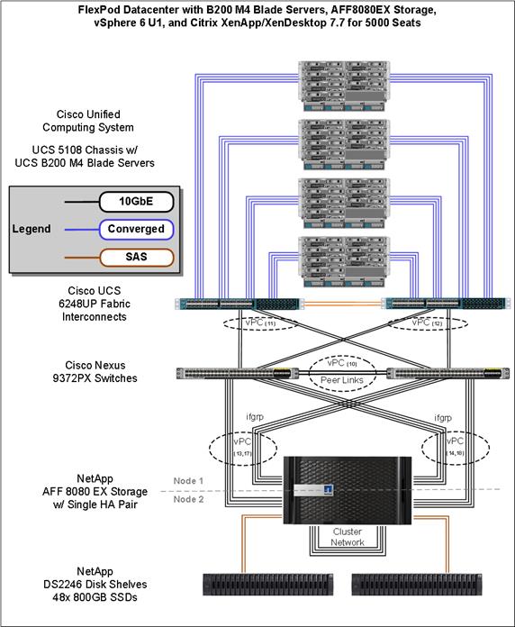
The workload contains the following hardware as shown in Figure 20:
§ Two Cisco Nexus 9372PX Layer 2 Access Switches
§ Four Cisco UCS 5108 Blade Server Chassis with two built-in UCS-IOM-2208XP IO Modules
§ Two Cisco UCS B200 M4 Blade servers with Intel Xeon E5-2660v3 2.6-GHz 10-core processors, 128GB RAM 2133-MHz, and VIC1340 mezzanine cards for the hosted infrastructure with N+1 server fault tolerance
§ Twenty-six Cisco UCS B200 M4 Blade servers with Intel Xeon E5-2680v3 2.5-GHz 12-core processors, 384GB RAM 1866-MHz, and VIC1340 mezzanine cards for the virtual desktop workloads with N+1 server fault tolerance
§ NetApp AFF8080EX dual controller storage system, two DS2246 Disk Shelves, 48x 800GB SSDs10GE ports for iSCSI and NFS/CIFS connectivity respectively
§ (Test Rig not part of solution) Sixteen Cisco UCS B200M3 Blade servers with Intel E5-2680 v2 processors, 256GB RAM, and VIC1240 mezzanine cards plus a NetApp FAS2240 for the Login VSI launcher and logging infrastructure
The NetApp AFF8080 configuration is detailed later in this document.
Logical Architecture
The logical architecture of the validated solution is designed to support up to 5000 users within a single Cisco UCS Mini chassis containing seven blades, which provides physical redundancy for the blade servers for each workload type.
Figure 21 outlines the logical architecture of the test environment.
Figure 21 Logical Architecture Overview
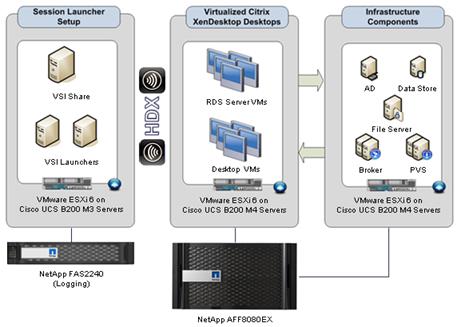
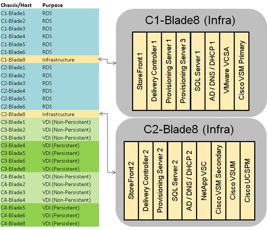
Table 64 outlines all the servers in the configurations.
Table 64 Infrastructure Architecture
| Server Name | Location | Purpose |
| C1-Blade8, C2-Blade8 | Physical – Chassis 1, 2 | ESXi 6.0 Hosts Infrastructure VMs Windows 2012-R2, VCSA, VSM, VSUM |
| C1-Blade1-6, C2-Blade1-6 | Physical – Chassis 1, 2 | ESXi 6.0 Hosts 96x XenApp RDS VMs |
| C3-Blade1-3, C4-Blade1-4 | Physical – Chassis 3, 4 | ESXi 6.0 Hosts 1200x XenDesktop VDI (Non-Persistent) VMs |
| C3-Blade4-6, 8 C4-Blade5, 6, 8 | Physical – Chassis 3, 4 | ESXi 6.0 Hosts 1200x XenDesktop VDI (Persistent) VMs |
| CTX-SF1 | C1-Blade8 | Citrix StoreFront Server 1 |
| CTX-XD1 | C1-Blade8 | XenDesktop Controller 1, Studio, Licensing |
| CTX-PVS1 | C1-Blade8 | Provisioning Services streaming server 1 |
| CTX-PVS3 | C1-Blade8 | Provisioning Services streaming server 3 |
| SQL1 | C1-Blade8 | SQL Server 1 (Always On) |
| AD-DC1 | C1-Blade8 | Active Directory Domain Controller 1 |
| VCSA | C1-Blade8 | VMware vCenter Server Appliance |
| VSM_primary | C1-Blade8 | Cisco Virtual Supervisor Module |
| CTX-SF2 | C2-Blade8 | Citrix StoreFront Server 2 |
| CTX-XD2 | C2-Blade8 | XenDesktop Controller 2, Director |
| CTX-PVS2 | C2-Blade8 | Provisioning Services streaming server 2 |
| SQL2 | C2-Blade8 | SQL Server 2 (Always On) |
| AD-DC2 | C2-Blade8 | Active Directory Domain Controller 2 |
| NA-VSC | C2-Blade8 | NetApp Virtual Storage Console |
| VSM_secondary | C2-Blade8 | Cisco Virtual Supervisor Module |
| VSUM | C2-Blade8 | Cisco Virtual Switch Update Manager |
| UCSPM | C2-Blade8 | Cisco UCS Performance Manager |
|
|
|
|
Software Revisions
This section includes the software versions of the primary products installed in the environment.
Table 65 Software Revisions
| Vendor | Product | Version |
| Cisco | UCS Component Firmware | 3.1(1e) bundle release |
| Cisco | UCS Manager | 3.1(1e) bundle release |
| Cisco | UCS B200 M4 Blades | 3.1(1e) bundle release |
| Cisco | VIC 1340 | 4.1(1d) |
| Cisco | Nexus 1000V | 5.2.1 |
| Cisco | Virtual Switch Update Manager | 2.0 |
| Cisco | UCS Performance Manager | 2.0 |
| Citrix | XenApp VDA | 7.7.0.6111 |
| Citrix | XenDesktop VDA | 7.7.0.6111 |
| Citrix | XenDesktop Controller | 7.7.0.6111 |
| Citrix | Provisioning Services | 7.7.0.6020 |
| Citrix | StoreFront Services | 3.0.1.57 |
| VMware | vCenter Server Appliance | 6.0.0.3040890 |
| VMware | vSphere ESXi 6.0 Update 1a | 6.0.0.3073146 |
| NetApp | VSC for VMware | 6.1.5250 |
| NetApp | Clustered Data ONTAP | 8.3.2 |
| NetApp | OnCommand System Manager | 8.3.2 |
Configuration Guidelines
The Citrix XenDesktop solution described in this document provides details for configuring a fully redundant, highly-available configuration. Configuration guidelines are provided that refer to which redundant component is being configured with each step, whether that be A or B. For example Nexus A and Nexus B identify the pair of Cisco Nexus switches that are configured. The Cisco UCS Fabric Interconnects are configured similarly.
![]() This document is intended to allow the reader to configure the Citrix XenDesktop 7.7 customer environment as stand-alone solution.
This document is intended to allow the reader to configure the Citrix XenDesktop 7.7 customer environment as stand-alone solution.
VLANs
The VLAN configuration recommended for the environment includes a total of seven VLANs as outlined in Table 66.
| VLAN Name | VLAN ID | VLAN Purpose |
| Default | 1 | Native VLAN |
| In-Band-Mgmt | 60 | VLAN for in-band management interfaces |
| Infra-Mgmt | 61 | VLAN for Virtual Infrastructure |
| CIFS | 62 | VLAN for CIFS traffic |
| NFS | 63 | VLAN for Infrastructure NFS traffic |
| iSCSI-A | 64 | VLAN for Fabric A iSCSI |
| iSCSI-B | 65 | VLAN for Fabric B iSCSI |
| vMotion | 66 | VLAN for VMware vMotion |
| VDI | 102 | Virtual Desktop traffic |
| OB-Mgmt | 164 | VLAN for out-of-band management interfaces |
VMware Clusters
We utilized two VMware Clusters in one vCenter datacenter to support the solution and testing environment:
§ VDI Cluster FlexPod Data Center with Cisco UCS
— Infrastructure: Infra VMs (vCenter, Active Directory, DNS, DHCP, SQL Server, XenDesktop Controllers, Provisioning Servers, and NetApp VSC, VSMs, etc.)
— RDS: XenApp RDS VMs (Windows Server 2012 R2)
— VDI NonPersistent: XenDesktop VDI VMs (Windows 7 SP1 32-bit non-persistent virtual desktops provisioned with PVS)
— VDI Persistent: XenDesktop VDI VMs (Windows 7 SP1 32-bit persistent virtual desktops provisioned with NetApp VSC)
![]() In cases where the design will support a higher amount of users (for example, greater than 2,000 seats with two or more chassis), the infrastructure VMs will be hosted on dedicated servers and contained in a separate cluster from the user workload.
In cases where the design will support a higher amount of users (for example, greater than 2,000 seats with two or more chassis), the infrastructure VMs will be hosted on dedicated servers and contained in a separate cluster from the user workload.
§ VSI Launchersand Launcher Cluster
— Launcher: Login VSI Cluster (The Login VSI launcher infrastructure was connected using the same set of switches and vCenter instance, but was hosted on separate storage and servers.)
Figure 22 vCenter Data Center and Clusters Deployed
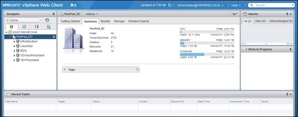
This section details the configuration and tuning that was performed on the individual components to produce a complete, validated solution.
Configuration Topology for a Scalable XenApp/XenDesktop 7.7 Mixed Workload Desktop Virtualization Solution
Figure 23 Component Layers for the FlexPod Data Center with Cisco UCS
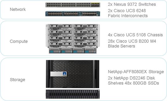
Figure 23 above captures the architectural diagram for the purpose of this study. The architecture is divided into three distinct layers:
§ Cisco UCS Compute Platform
§ Network Access layer and LAN
§ Storage Access to the NetApp AFF8080 EX
Figure 24 details the physical connectivity configuration of the Citrix XenDesktop 7.7 environment.
Figure 24 Cabling Diagram of the FlexPod Data Center with Cisco UCS
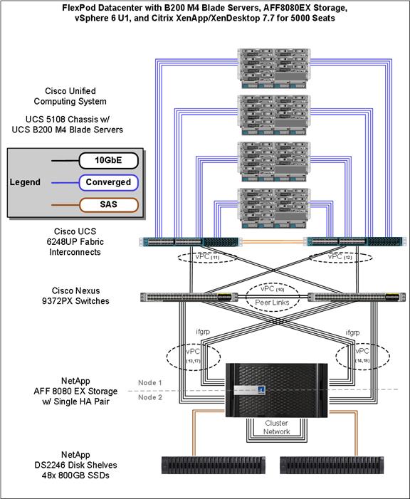
Table 67 through Table 72 provide the details of all the connections in use.
Table 67 Cisco Nexus 9372-A Cabling Information
| Local Device | Local Port | Connection | Remote Device | Remote Port |
| Cisco Nexus 9372 A
| Eth1/1 | 10GbE | NetApp Controller 2 | e0e |
| Eth1/2 | 10GbE | NetApp Controller 2 | e1a | |
| Eth1/3 | 10GbE | NetApp Controller 1 | e0e | |
| Eth1/4 | 10GbE | NetApp Controller 1 | e4a | |
| Eth1/5 | 10GbE | NetApp Controller 2 | e0f | |
| Eth1/6 | 10GbE | NetApp Controller 2 | e4a | |
| Eth1/7 | 10GbE | NetApp Controller 1 | e0f | |
| Eth1/8 | 10GbE | NetApp Controller 1 | e1a | |
| Eth1/17 | 10GbE | Cisco UCS fabric interconnect A | Eth2/1 | |
| Eth1/18 | 10GbE | Cisco UCS fabric interconnect A | Eth2/2 | |
| Eth1/19 | 10GbE | Cisco UCS fabric interconnect B | Eth2/3 | |
| Eth1/20 | 10GbE | Cisco UCS fabric interconnect B | Eth2/4 | |
| Eth1/49 | 40GbE | Cisco Nexus 9372 B | Eth1/49 | |
| Eth1/50 | 40GbE | Cisco Nexus 9372 B | Eth1/50 | |
|
| MGMT0 | GbE | GbE management switch | Any |
![]() For devices requiring GbE connectivity, use the GbE Copper SFP+s (GLC-T=).
For devices requiring GbE connectivity, use the GbE Copper SFP+s (GLC-T=).
Table 68 Cisco Nexus 9372-B Cabling Information
| Local Device | Local Port | Connection | Remote Device | Remote Port |
| Cisco Nexus 9372 B
| Eth1/1 | 10GbE | NetApp Controller 2 | e0g |
| Eth1/2 | 10GbE | NetApp Controller 2 | e1b | |
| Eth1/3 | 10GbE | NetApp Controller 1 | e0g | |
| Eth1/4 | 10GbE | NetApp Controller 1 | e4b | |
| Eth1/5 | 10GbE | NetApp Controller 2 | e0h | |
| Eth1/6 | 10GbE | NetApp Controller 2 | e4b | |
| Eth1/7 | 10GbE | NetApp Controller 1 | e0h | |
| Eth1/8 | 10GbE | NetApp Controller 1 | e1b | |
| Eth1/17 | 10GbE | Cisco UCS fabric interconnect A | Eth2/1 | |
| Eth1/18 | 10GbE | Cisco UCS fabric interconnect A | Eth2/2 | |
| Eth1/19 | 10GbE | Cisco UCS fabric interconnect B | Eth2/3 | |
| Eth1/20 | 10GbE | Cisco UCS fabric interconnect B | Eth2/4 | |
| Eth1/49 | 40GbE | Cisco Nexus 9372 B | Eth1/49 | |
| Eth1/50 | 40GbE | Cisco Nexus 9372 B | Eth1/50 | |
|
| MGMT0 | GbE | GbE management switch | Any |
Table 69 NetApp Controller-1 Cabling Information
| Local Device | Local Port | Connection | Remote Device | Remote Port |
| NetApp AFF8080 Node 1 | e0M | 100MbE | 100MbE management switch | Any |
| e0i | GbE | GbE management switch | Any | |
| e0P | GbE | SAS shelves | ACP port | |
| e0a | 10GbE | NetApp Controller 2 | e0a | |
| e0b | 10GbE | NetApp Controller 2 | e0b | |
| e0c | 10GbE | NetApp Controller 2 | e0c | |
| e0d | 10GbE | NetApp Controller 2 | e0d | |
| e0e | 10GbE | Cisco Nexus 9372 A | Eth1/3 | |
| e0g | 10GbE | Cisco Nexus 9372 B | Eth1/3 | |
| e4a | 10GbE | Cisco Nexus 9372 A | Eth1/4 | |
| e4b | 10GbE | Cisco Nexus 9372 B | Eth1/4 | |
| e0f | 10GbE | Cisco Nexus 9372 A | Eth1/7 | |
| e0h | 10GbE | Cisco Nexus 9372 B | Eth1/7 | |
| e1a | 10GbE | Cisco Nexus 9372 A | Eth1/8 | |
| e1b | 10GbE | Cisco Nexus 9372 B | Eth1/8 |
![]() When the term e0M is used, the physical Ethernet port to which the table is referring is the port indicated by a wrench icon on the rear of the chassis.
When the term e0M is used, the physical Ethernet port to which the table is referring is the port indicated by a wrench icon on the rear of the chassis.
Table 70 NetApp Controller 2 Cabling Information
| Local Device | Local Port | Connection | Remote Device | Remote Port |
| NetApp AFF8080 Node 2 | e0M | 100MbE | 100MbE management switch | Any |
| e0i | GbE | GbE management switch | Any | |
| e0P | GbE | SAS shelves | ACP port | |
| e0a | 10GbE | NetApp Controller 2 | e0a | |
| e0b | 10GbE | NetApp Controller 2 | e0b | |
| e0c | 10GbE | NetApp Controller 2 | e0c | |
| e0d | 10GbE | NetApp Controller 2 | e0d | |
| e0e | 10GbE | Cisco Nexus 9372 A | Eth1/1 | |
| e0g | 10GbE | Cisco Nexus 9372 B | Eth1/1 | |
| e1a | 10GbE | Cisco Nexus 9372 A | Eth1/2 | |
| e1b | 10GbE | Cisco Nexus 9372 B | Eth1/2 | |
| e0f | 10GbE | Cisco Nexus 9372 A | Eth1/5 | |
| e0h | 10GbE | Cisco Nexus 9372 B | Eth1/5 | |
| e4a | 10GbE | Cisco Nexus 9372 A | Eth1/6 | |
| e4b | 10GbE | Cisco Nexus 9372 B | Eth1/6 |
Table 71 Cisco UCS Fabric Interconnect A Cabling Information
| Local Device | Local Port | Connection | Remote Device | Remote Port |
| Cisco UCS Fabric Interconnect A
| Eth2/1 | 10GbE | Cisco Nexus 9372 A | Eth1/17 |
| Eth2/2 | 10GbE | Cisco Nexus 9372 A | Eth1/18 | |
| Eth2/3 | 10GbE | Cisco Nexus 9372 B | Eth1/19 | |
| Eth2/4 | 10GbE | Cisco Nexus 9372 B | Eth1/20 | |
| Eth1/1 | 10GbE | Cisco UCS Chassis1 FEX A | IOM 1/1 | |
| Eth1/2 | 10GbE | Cisco UCS Chassis1 FEX A | IOM 1/2 | |
| Eth1/3 | 10GbE | Cisco UCS Chassis1 FEX A | IOM 1/3 | |
| Eth1/4 | 10GbE | Cisco UCS Chassis1 FEX A | IOM 1/4 | |
| Eth1/5 | 10GbE | Cisco UCS Chassis2 FEX A | IOM 1/1 | |
| Eth1/6 | 10GbE | Cisco UCS Chassis2 FEX A | IOM 1/2 | |
| Eth1/7 | 10GbE | Cisco UCS Chassis2 FEX A | IOM 1/3 | |
| Eth1/8 | 10GbE | Cisco UCS Chassis2 FEX A | IOM 1/4 | |
| Eth1/9 | 10GbE | Cisco UCS Chassis3 FEX A | IOM 1/1 | |
| Eth1/10 | 10GbE | Cisco UCS Chassis3 FEX A | IOM 1/2 | |
| Eth1/11 | 10GbE | Cisco UCS Chassis3 FEX A | IOM 1/3 | |
| Eth1/12 | 10GbE | Cisco UCS Chassis3 FEX A | IOM 1/4 | |
| Eth1/13 | 10GbE | Cisco UCS Chassis4 FEX A | IOM 1/1 | |
| Eth1/14 | 10GbE | Cisco UCS Chassis4 FEX A | IOM 1/2 | |
| Eth1/15 | 10GbE | Cisco UCS Chassis4 FEX A | IOM 1/3 | |
| Eth1/16 | 10GbE | Cisco UCS Chassis4 FEX A | IOM 1/4 | |
| MGMT0 | GbE | GbE management switch | Any | |
| L1 | GbE | Cisco UCS fabric interconnect B | L1 | |
|
| L2 | GbE | Cisco UCS fabric interconnect B | L2 |
Table 72 Cisco UCS Fabric Interconnect B Cabling Information
| Local Device | Local Port | Connection | Remote Device | Remote Port |
| Cisco UCS Fabric Interconnect B
| Eth2/1 | 10GbE | Cisco Nexus 9372 A | Eth1/17 |
| Eth2/2 | 10GbE | Cisco Nexus 9372 A | Eth1/18 | |
| Eth2/3 | 10GbE | Cisco Nexus 9372 B | Eth1/19 | |
| Eth2/4 | 10GbE | Cisco Nexus 9372 B | Eth1/20 | |
| Eth1/1 | 10GbE | Cisco UCS Chassis1 FEX B | IOM 2/1 | |
| Eth1/2 | 10GbE | Cisco UCS Chassis1 FEX B | IOM 2/2 | |
| Eth1/3 | 10GbE | Cisco UCS Chassis1 FEX B | IOM 2/3 | |
| Eth1/4 | 10GbE | Cisco UCS Chassis1 FEX B | IOM 2/4 | |
| Eth1/5 | 10GbE | Cisco UCS Chassis2 FEX B | IOM 2/1 | |
| Eth1/6 | 10GbE | Cisco UCS Chassis2 FEX B | IOM 2/2 | |
| Eth1/7 | 10GbE | Cisco UCS Chassis2 FEX B | IOM 2/3 | |
| Eth1/8 | 10GbE | Cisco UCS Chassis2 FEX B | IOM 2/4 | |
| Eth1/9 | 10GbE | Cisco UCS Chassis3 FEX B | IOM 2/1 | |
| Eth1/10 | 10GbE | Cisco UCS Chassis3 FEX B | IOM 2/2 | |
| Eth1/11 | 10GbE | Cisco UCS Chassis3 FEX B | IOM 2/3 | |
| Eth1/12 | 10GbE | Cisco UCS Chassis3 FEX B | IOM 2/4 | |
| Eth1/13 | 10GbE | Cisco UCS Chassis4 FEX B | IOM 2/1 | |
| Eth1/14 | 10GbE | Cisco UCS Chassis4 FEX B | IOM 2/2 | |
| Eth1/15 | 10GbE | Cisco UCS Chassis4 FEX B | IOM 2/3 | |
| Eth1/16 | 10GbE | Cisco UCS Chassis4 FEX B | IOM 2/4 | |
| MGMT0 | GbE | GbE management switch | Any | |
| L1 | GbE | Cisco UCS fabric interconnect B | L1 | |
|
| L2 | GbE | Cisco UCS fabric interconnect B | L2 |
Cisco Unified Computing System Configuration
This section talks about the Cisco UCS configuration that was done as part of the infrastructure build out. The racking, power and installation of the chassis are described in the install guide (see www.cisco.com/c/en/us/support/servers-unified-computing/ucs-manager/products-installation-guides-list.html) and it is beyond the scope of this document. For more information about each step, refer to the following documents:
Cisco UCS Manager Configuration Guides – GUI and Command Line Interface (CLI) Cisco UCS Manager - Configuration Guides - Cisco
Configure Fabric Interconnect at Console
To configure the fabric interconnect, complete the following steps:
1. Connect a console cable to the console port on what will become the primary fabric interconnect.
2. If the fabric interconnect was previously deployed and you want to erase it to redeploy, follow these steps:
a. Login with the existing user name and password
b. Enter: connect local-mgmt
c. Enter: erase config
d. Enter: yes to confirm
3. After the fabric interconnect restarts, the out-of-box first time installation prompt appears, type console and press Enter.
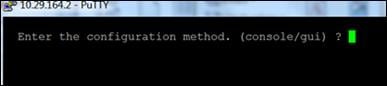
4. Type “setup” at the setup/restore prompt, then press Enter.
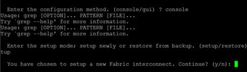
5. Type “y” then press Enter to confirm the setup.
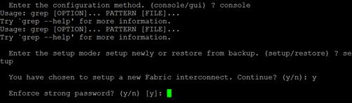
6. Type “y” or “n” depending on your organization’s security policies, then press Enter.
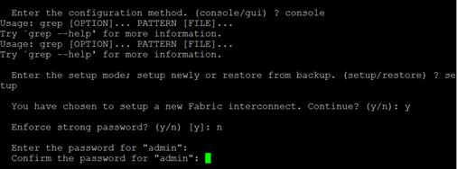
7. Enter and confirm the password.
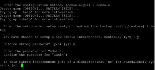
8. Type “yes” to create the cluster for the Fabric Interconnects, then type A to set the FI to primary.

9. Complete the setup dialog questions.
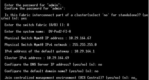
10. Review the selections and type “yes”.
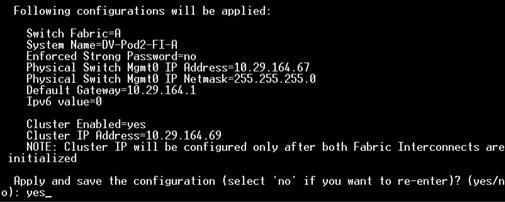
11. Console onto second fabric interconnect, select console as the configuration method and provide the following inputs.
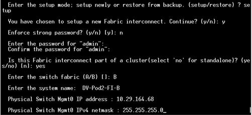
12. Open a web browser and go to the Virtual IP address configured above.
13. Click the Launch UCS Manager, login with admin as the user name and the password you configured above.
Base Cisco UCS System Configuration
To configure the Cisco Unified Computing System, complete the following steps:
1. Open a web browser and navigate to the Cisco UCS 6248 Fabric Interconnect cluster address.
2. Click the Launch UCS Manager link to download the Cisco UCS Manager software.
3. If prompted to accept security certificates, accept as necessary.
4. When prompted, enter admin as the user name and enter the administrative password.
5. To log in to Cisco UCS Manager, click Login.
Cisco UCS Manager Software to Version 3.1(1e)
The Fabric Interconnects come with Cisco UCS Manager. This document assumes the use of Cisco UCS Manager Software version 3.1(1e). To upgrade the Cisco UCS Manager software and the Cisco UCS 6248 Fabric Interconnect software to a higher version of the firmware,) refer to Cisco UCS Manager Install and Upgrade Guides.
Add a Block of IP Addresses for Out-of-Band KVM Access
To create a block of IP addresses for server keyboard, video, mouse (KVM) access in the Cisco UCS environment, complete the following steps:
![]() This block of IP addresses should be in the same subnet as the management IP addresses for the Cisco UCS Manager.
This block of IP addresses should be in the same subnet as the management IP addresses for the Cisco UCS Manager.
1. In Cisco UCS Manager, in the navigation pane, click the LAN tab.
2. Select Pools > root > IP Pools > IP Pool ext-mgmt.
3. In the Actions pane, select Create Block of IP Addresses.
4. Enter the starting IP address of the block and the number of IP addresses required, and the subnet and gateway information.
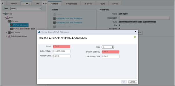
5. Click OK to create the IP block.
6. Click OK in the confirmation message.
Synchronize Cisco UCS to NTP
To synchronize the Cisco UCS environment to the NTP server, complete the following steps:
1. In Cisco UCS Manager, in the navigation pane, click the Admin tab.
2. Select All > Timezone Management.
3. In the Properties pane, select the appropriate time zone in the Timezone menu.
4. Click Save Changes, and then click OK.
5. Click Add NTP Server.
6. Enter <<var_global_ntp_server_ip>> and click OK.
7. Click OK.
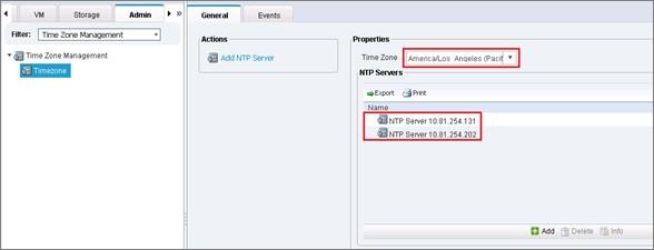
Edit Chassis Discovery Policy
Setting the discovery policy simplifies the addition of B-Series Cisco UCS chassis and Cisco UCS C-Series servers.
To modify the chassis discovery policy, complete the following steps:
1. In Cisco UCS Manager, in the navigation pane, click the Equipment node and select Equipment in the list on the left.
2. In the right pane, click the Policies tab.
3. Under Global Policies, set the Chassis/FEX Discovery Policy to 4-link.
4. Set the Link Grouping Preference to Port Channel.
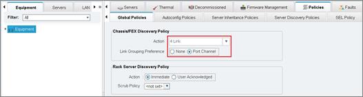
5. Click Save Changes.
6. Click OK.
Enable Server Uplink and Storage Ports
To enable server and uplink ports, complete the following steps:
1. In Cisco UCS Manager, click the Equipment tab in the navigation pane.
2. Select Equipment > Fabric Interconnects > Fabric Interconnect A (primary) > Fixed Module.
3. Expand Ethernet Ports.
4. Select the ports that are connected to the four Cisco UCS chassis, right-click them, and select “Configure as Server Port.”
5. Click Yes to confirm server ports and click OK.
6. Verify that the ports connected to the four Cisco UCS chassis are now configured as server ports.
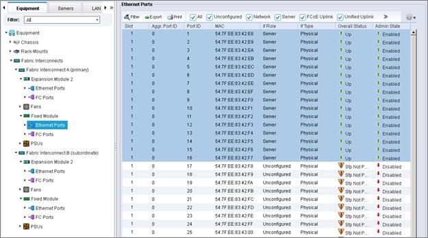
7. Select Equipment > Fabric Interconnects > Fabric Interconnect A (primary) > Fixed Module > Expansion Module 2.
8. Expand Ethernet Ports.
9. Select the ports that are connected to the Cisco Nexus upstream switches, right-click them, and select “Configure as Uplink Port”.
10. Click Yes to confirm uplink network ports and click OK.
11. Verify that the ports connected to the Cisco Nexus upstream switches are now configured as network ports.
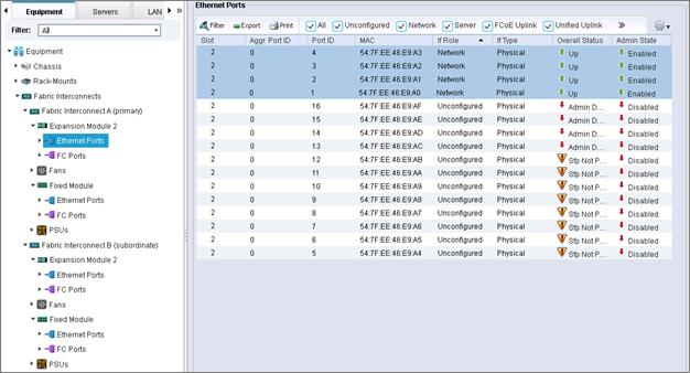
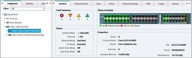
12. Repeat the above steps to the Fabric Interconnect B (subordinate) configuring the server and uplink ports.
Acknowledge Cisco UCS Chassis
To acknowledge all Cisco UCS chassis, complete the following steps:
1. In Cisco UCS Manager, click the Equipment tab in the navigation pane.
2. Expand Chassis and select each chassis that is listed.
3. Right-click each chassis and select Acknowledge Chassis.
4. Click Yes and then click OK to complete acknowledging the chassis.
Create Uplink Port Channels to Cisco Nexus 9372PX Switches
To configure the necessary port channels out of the Cisco UCS environment, complete the following steps:
1. In Cisco UCS Manager, click the LAN tab in the navigation pane.
![]() In this procedure, two port channels are created: one from fabric A to both Cisco Nexus switches and one from fabric B to both Cisco Nexus switches.
In this procedure, two port channels are created: one from fabric A to both Cisco Nexus switches and one from fabric B to both Cisco Nexus switches.
2. Under LAN > LAN Cloud, expand the Fabric A tree.
3. Right-click Port Channels.
4. Select Create Port Channel.
5. Enter 11 as the unique ID of the port channel.
6. Enter vPC-11-Nexus as the name of the port channel.
7. Click Next.
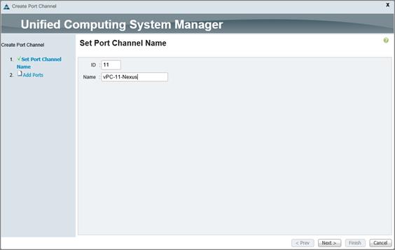
8. Select the following ports to be added to the port channel:
— Slot ID 2 and port 1
— Slot ID 2 and port 2
— Slot ID 2 and port 3
— Slot ID 2 and port 4
9. Click >> to add the ports to the port channel.
10. Click Finish to create the port channel.
11. Click OK.
12. In the navigation pane, under LAN > LAN Cloud, expand the fabric B tree.
13. Right-click Port Channels.
14. Select Create Port Channel.
15. Enter 12 as the unique ID of the port channel.
16. Enter vPC-12-Nexus as the name of the port channel.
17. Click Next.
18. Select the following ports to be added to the port channel:
— Slot ID 2 and port 1
— Slot ID 2 and port 2
— Slot ID 2 and port 3
— Slot ID 2 and port 4
19. Click >> to add the ports to the port channel.
20. Click Finish to create the port channel.
21. Click OK.
![]() As a checkpoint, the configuration should be in line with the following connectivity diagram.
As a checkpoint, the configuration should be in line with the following connectivity diagram.
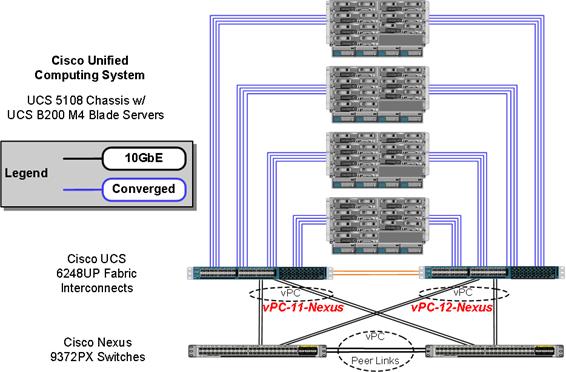
Create an Organization
Organizations are used to organize resources and restrict access to various groups within the IT organization, thereby enabling multi-tenancy of the compute resources.
![]() Although this document does not assume the use of organizations this procedure provides instructions for creating one.
Although this document does not assume the use of organizations this procedure provides instructions for creating one.
To configure an organization in the Cisco UCS environment, complete the following steps:
1. In Cisco UCS Manager, from the New menu in the toolbar at the top of the window, select Create Organization.
2. Enter a name for the organization.
3. Optional: Enter a description for the organization.
4. Click OK.
5. Click OK in the confirmation message.
Create Resource Pools
This section details how to create the MAC address, iSCSI IQN, iSCSI IP, UUID suffix and server pools.
Create MAC Address Pools
To configure the necessary MAC address pools for the Cisco UCS environment, complete the following steps:
1. In Cisco UCS Manager, click the LAN tab in the navigation pane.
2. Select Pools > root.
![]() In this procedure, two MAC address pools are created, one for each switching fabric.
In this procedure, two MAC address pools are created, one for each switching fabric.
3. Right-click MAC Pools under the root organization.
4. Select Create MAC Pool to create the MAC address pool.
5. Enter MAC_Pool_A as the name of the MAC pool.
6. Optional: Enter a description for the MAC pool.
![]() Keep the Assignment Order at Default.
Keep the Assignment Order at Default.
7. Click Next.
8. Click Add.
9. Specify a starting MAC address.
![]() For the FlexPod solution, the recommendation is to place 0A in the next-to-last octet of the starting MAC address to identify all of the MAC addresses as fabric A addresses.
For the FlexPod solution, the recommendation is to place 0A in the next-to-last octet of the starting MAC address to identify all of the MAC addresses as fabric A addresses.
10. Specify a size for the MAC address pool that is sufficient to support the available blade or server resources.
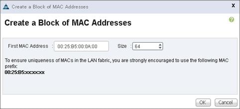
11. Click OK.
12. Click Finish.
13. In the confirmation message, click OK.
14. Right-click MAC Pools under the root organization.
15. Select Create MAC Pool to create the MAC address pool.
16. Enter MAC_Pool_B as the name of the MAC pool.
17. Optional: Enter a description for the MAC pool.
18. Click Next.
19. Click Add.
20. Specify a starting MAC address.
![]() For the FlexPod solution, it is recommended to place 0B in the next to last octet of the starting MAC address to identify all the MAC addresses in this pool as fabric B addresses.
For the FlexPod solution, it is recommended to place 0B in the next to last octet of the starting MAC address to identify all the MAC addresses in this pool as fabric B addresses.
21. Specify a size for the MAC address pool that is sufficient to support the available blade or server resources.
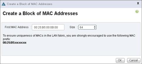
22. Click OK.
23. Click Finish.
24. In the confirmation message, click OK.
Create IQN Pools for iSCSI Boot
To configure the necessary IQN pools for the Cisco UCS environment, complete the following steps.
1. In the UCS Manager, select the SAN tab on the left.
2. Select Pools > root.
3. Right-click IQN Pools under the root organization.
4. Select Create IQN Suffix Pool to create the IQN pool.
5. Enter IQN_Pool for the name of the IQN pool.
6. Optional: Enter a description for the IQN pool.
7. Enter iqn.1992-08.com.cisco as the prefix
8. Select Sequential for Assignment Order.
9. Click Next.
10. Click Add.
11. Enter ucs-host as the suffix.
12. Enter 1 in the From field.
13. Specify a size of the IQN block sufficient to support the available server resources.
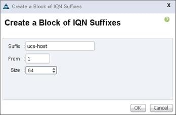
14. Click OK.
15. Click Finish.
16. In the message box that displays, click OK.
Create IP Pools for iSCSI Boot
To configure the necessary IP pools for iSCSI boot , complete the following steps:
1. In Cisco UCS Manager, select the LAN tab on the left.
2. Select Pools > root.
![]() Two IP pools are created, one for each switching fabric.
Two IP pools are created, one for each switching fabric.
3. Right-click IP Pools under the root organization.
4. Select Create IP Pool to create the IP pool.
5. Enter iSCSI_IP_Pool_A for the name of the IP pool.
6. Optional: Enter a description of the IP pool.
7. Select Sequential for Assignment Order.
8. Click Next.
9. Click Add.
10. In the From field, enter the beginning of the range to assign as iSCSI IP addresses.
11. Set the size to enough addresses to accommodate the servers.
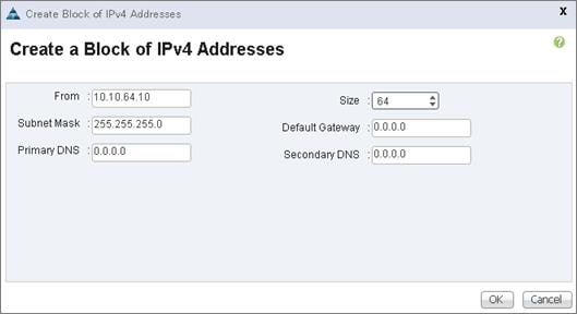
12. Click OK.
13. Click Finish.
14. Right-click IP Pools under the root organization.
15. Select Create IP Pool to create the IP pool.
16. Enter iSCSI_IP_Pool_B for the name of the IP pool.
17. Optional: Enter a description of the IP pool.
18. Select Sequential for Assignment Order.
19. Click Next.
20. Click Add.
21. In the From field, enter the beginning of the range to assign as iSCSI IP addresses.
22. Set the size to enough addresses to accommodate the servers.
23. Click OK.
24. Click Finish.
Create UUID Suffix Pool
To configure the necessary universally unique identifier (UUID) suffix pool for the Cisco UCS environment, complete the following steps:
1. In Cisco UCS Manager, click the Servers tab in the navigation pane.
2. Select Pools > root.
3. Right-click UUID Suffix Pools.
4. Select Create UUID Suffix Pool.
5. Enter UUID_Pool as the name of the UUID suffix pool.
6. Optional: Enter a description for the UUID suffix pool.
7. Keep the prefix at the derived option.
8. Select Sequential for Assignment Order.
9. Click Next.
10. Click Add to add a block of UUIDs.
11. Keep the From field at the default setting.
12. Specify a size for the UUID block that is sufficient to support the available blade or server resources.
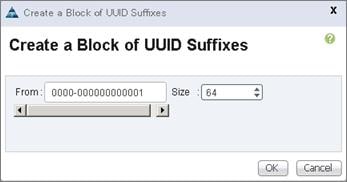
13. Click OK.
14. Click Finish.
15. Click OK.
Create Server Pool
To configure the necessary server pool for the Cisco UCS environment, complete the following steps:
![]() Consider creating unique server pools to achieve the granularity that is required in your environment.
Consider creating unique server pools to achieve the granularity that is required in your environment.
1. In Cisco UCS Manager, click the Servers tab in the navigation pane.
2. Select Pools > root.
3. Right-click Server Pools.
4. Select Create Server Pool.
5. Enter Server_Pool as the name of the server pool.
6. Optional: Enter a description for the server pool.
7. Click Next
8. Select all servers to be used for the solution and click >> to add them to the Server_Pool server pool.
9. Click Finish.
10. Click OK.
Create VLANs
To configure the necessary virtual local area networks (VLANs) for the Cisco UCS environment, complete the following steps:
1. In Cisco UCS Manager, click the LAN tab in the navigation pane.
![]() In this procedure, 10 unique VLANs are created. Refer to Table 73 .
In this procedure, 10 unique VLANs are created. Refer to Table 73 .
| VLAN Name | VLAN ID | VLAN Purpose | vNIC Assignment |
| Default | 1 | Native VLAN | vNIC-Template-A vNIC-Template-B |
| In-Band-Mgmt | 60 | VLAN for in-band management interfaces | vNIC-Template-A vNIC-Template-B |
| Infra-Mgmt | 61 | VLAN for Virtual Infrastructure | vNIC-Template-A vNIC-Template-B |
| CIFS | 62 | VLAN for CIFS traffic | vNIC-Template-A vNIC-Template-B |
| NFS | 63 | VLAN for Infrastructure NFS traffic | vNIC-Template-A vNIC-Template-B |
| iSCSI-A | 64 | VLAN for Fabric A iSCSI | iSCSI-Template-A |
| iSCSI-B | 65 | VLAN for Fabric B iSCSI | iSCSI-Template-B |
| vMotion | 66 | VLAN for VMware vMotion | vNIC-Template-A vNIC-Template-B |
| VDI | 102 | Virtual Desktop traffic | vNIC-Template-A vNIC-Template-B |
| OB-Mgmt | 164 | VLAN for out-of-band management interfaces | vNIC-Template-A vNIC-Template-B |
2. Select LAN > LAN Cloud.
3. Right-click VLANs.
4. Select Create VLANs.
5. Enter In-Band-Mgmt as the name of the VLAN to be used for in-band management traffic.
6. Keep the Common/Global option selected for the scope of the VLAN.
7. Enter VLAN ID.
8. Keep the Sharing Type as None.
9. Click OK, and then click OK again.
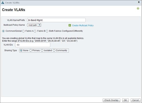
10. Repeat the above steps to create all VLANs and configure the Default VLAN as native.
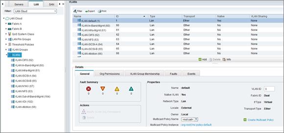
Create Host Firmware Package
Firmware management policies allow the administrator to select the corresponding packages for a given server configuration. These policies often include packages for adapter, BIOS, board controller, FC adapters, host bus adapter (HBA) option ROM, and storage controller properties.
To create a firmware management policy for a given server configuration in the Cisco UCS environment, complete the following steps:
1. In Cisco UCS Manager, click the Servers tab in the navigation pane.
2. Select Policies > root.
3. Right-click Host Firmware Packages.
4. Select Create Host Firmware Package.
5. Enter UCS-3.1.1d as the name of the host firmware package.
6. Leave Simple selected.
7. Select the version 3.1(1d) for the Blade Package and other UCS equipment if applicable.
8. Click OK to create the host firmware package.
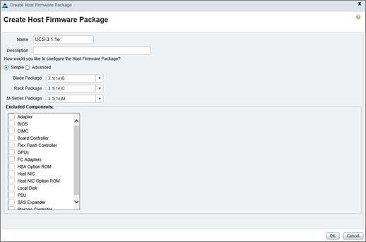
Set Jumbo Frames in Cisco UCS Fabric
To configure jumbo frames and enable quality of service in the Cisco UCS fabric, complete the following steps:
1. In Cisco UCS Manager, click the LAN tab in the navigation pane.
2. Select LAN > LAN Cloud > QoS System Class.
3. In the right pane, click the General tab.
4. On the Best Effort row, enter 9216 in the box under the MTU column.
5. Click Save Changes in the bottom of the window.
6. Click OK
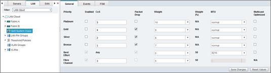
Create Local Disk Configuration Policy (Optional)
A local disk configuration for the Cisco UCS environment is necessary if the servers in the environment do not have a local disk.
![]() This policy should not be used on servers that contain local disks.
This policy should not be used on servers that contain local disks.
To create a local disk configuration policy, complete the following steps:
1. In Cisco UCS Manager, click the Servers tab in the navigation pane.
2. Select Policies > root.
3. Right-click Local Disk Config Policies.
4. Select Create Local Disk Configuration Policy.
5. Enter iSCSI-Boot as the local disk configuration policy name.
6. Change the mode to No Local Storage.
7. Click OK to create the local disk configuration policy.
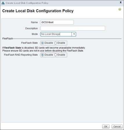
8. Click OK.
Create Network Control Policy for Cisco Discovery Protocol
To create a network control policy that enables Cisco Discovery Protocol (CDP) on virtual network ports, complete the following steps:
1. In Cisco UCS Manager, click the LAN tab in the navigation pane.
2. Select Policies > root.
3. Right-click Network Control Policies.
4. Select Create Network Control Policy.
5. Enter Enable-CDP as the policy name.
6. For CDP, select the Enabled option.
7. Click OK to create the network control policy.
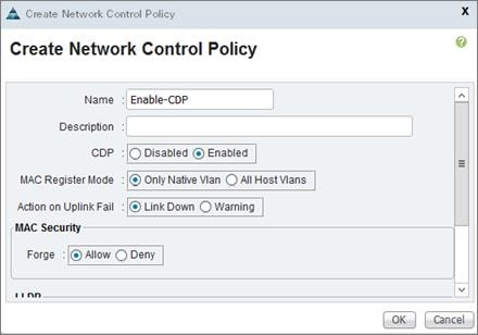
8. Click OK.
Create Power Control Policy
To create a power control policy for the Cisco UCS environment, complete the following steps:
1. In Cisco UCS Manager, click the Servers tab in the navigation pane.
2. Select Policies > root.
3. Right-click Power Control Policies.
4. Select Create Power Control Policy.
5. Enter No-Power-Cap as the power control policy name.
6. Change the power capping setting to No Cap.
7. Click OK to create the power control policy.
8. Click OK.
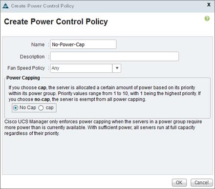
Create Server Pool Qualification Policy (Optional)
To create an optional server pool qualification policy for the Cisco UCS environment, complete the following steps:
![]() This example creates a policy for a Cisco UCS B200-M4 server.
This example creates a policy for a Cisco UCS B200-M4 server.
1. In Cisco UCS Manager, click the Servers tab in the navigation pane.
2. Select Policies > root.
3. Right-click Server Pool Policy Qualifications.
4. Select Create Server Pool Policy Qualification.
5. Name the policy UCS-B200-M4.
6. Select Create Server PID Qualifications.
7. Select UCSB-B200-M4 as the name.
8. Click OK to create the server PID qualification.
9. Click OK to create the policy then OK for the confirmation.
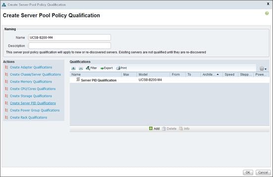
Create Server BIOS Policy
To create a server BIOS policy for the Cisco UCS environment, complete the following steps:
1. In Cisco UCS Manager, click the Servers tab in the navigation pane.
2. Select Policies > root.
3. Right-click BIOS Policies.
4. Select Create BIOS Policy.
5. Enter B200-M4-BIOS as the BIOS policy name.
6. Configure the BIOS policies as follows and click Finish.
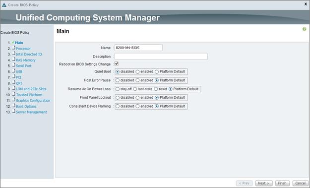
7. Click Next.
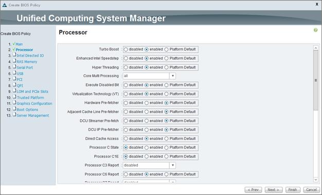
8. Scroll down and configure the remaining settings.
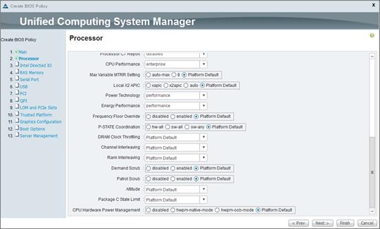
9. Click Next.
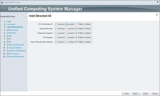
10. Click Finish.
Create vNIC/vHBA Placement Policy for Virtual Machine Infrastructure Hosts
To create a vNIC/vHBA placement policy for the virtual machine hosts, complete the following steps:
1. In Cisco UCS Manager, click the Servers tab in the navigation pane.
2. Select Policies > root.
3. Right-click vNIC/vHBA Placement Policies.
4. Select Create Placement Policy.
5. Enter VM-Host as the name of the placement policy.
6. Double-click All for Virtual Slot 1 and select Assigned Only.
7. Click OK, and then click OK again.
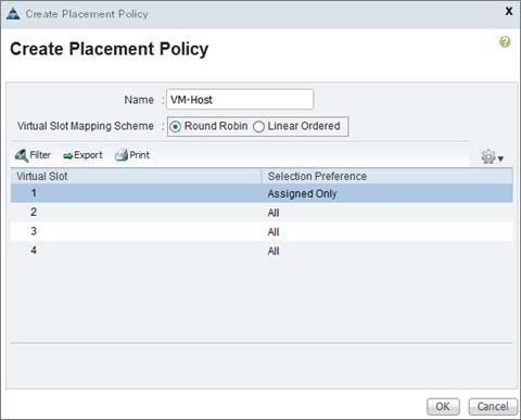
Configure Update Default Maintenance Policy
To update the default Maintenance Policy, complete the following steps:
1. In Cisco UCS Manager, click the Servers tab in the navigation pane.
2. Select Policies > root.
3. Select Maintenance Policies > default.
4. Change the Reboot Policy to User Ack.
5. Click Save Changes.
6. Click OK to accept the change.
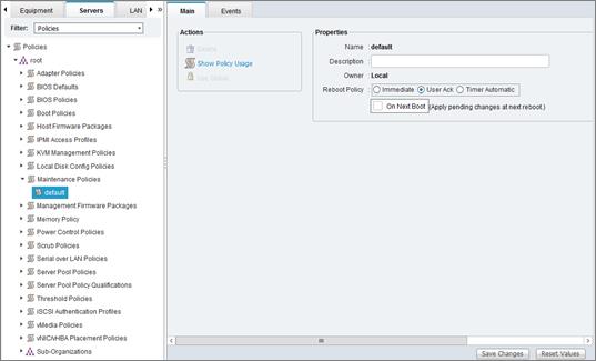
Create vNIC Templates
To create multiple virtual network interface card (vNIC) templates for the Cisco UCS environment, complete the following steps. A total of four vNIC Templates will be created.
Create Data vNICs
1. In Cisco UCS Manager, click the LAN tab in the navigation pane.
2. Select Policies > root.
3. Right-click vNIC Templates.
4. Select Create vNIC Template.
5. Enter vNIC-Template-A as the vNIC template name.
6. Keep Fabric A selected.
7. Do not select the Enable Failover checkbox.
8. Under Target, make sure that the VM checkbox is not selected.
9. Select Updating Template as the Template Type.
10. Under VLANs, select the checkboxes for CIFS, default, In-Band-Mgmt, Infra-Mgmt, N1KV, NFS, VDI, and vMotion VLANs.
11. Set default as the native VLAN.
12. For MTU, enter 9000.
13. In the MAC Pool list, select MAC_Pool_A.
14. In the Network Control Policy list, select Enable-CDP.
15. Click OK to create the vNIC template.
16. Click OK.
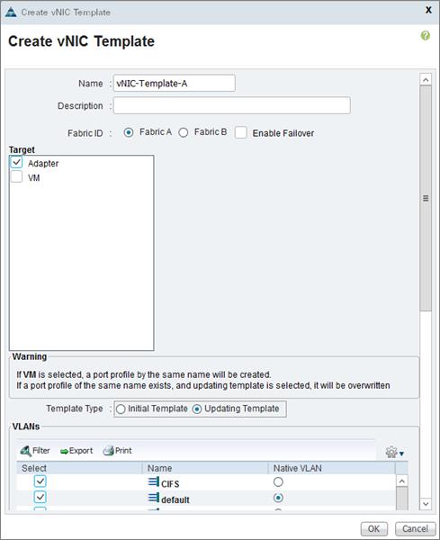
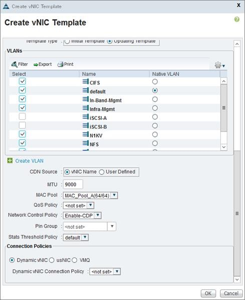
17. In the navigation pane, select the LAN tab.
18. Select Policies > root.
19. Right-click vNIC Templates.
20. Select Create vNIC Template
21. Enter vNIC-Template-B as the vNIC template name.
22. Select Fabric B.
23. Do not select the Enable Failover checkbox.
24. Under Target, make sure the VM checkbox is not selected.
25. Select Updating Template as the template type.
26. Under VLANs, select the checkboxes for IB-MGMT, INFRA-NFS, Native-VLAN, and vMotion VLANs.
27. Set default as the native VLAN.
28. For MTU, enter 9000.
29. In the MAC Pool list, select MAC_Pool_B.
30. In the Network Control Policy list, select Enable_CDP.
31. Click OK to create the vNIC template.
32. Click OK.
Create iSCSI vNICs
1. Select the LAN tab on the left.
2. Select Policies > root.
3. Right-click vNIC Templates.
4. Select Create vNIC Template.
5. Enter iSCSI-Template-A as the vNIC template name.
6. Leave Fabric A selected. Do not select the Enable Failover checkbox.
7. Under Target, make sure that the VM checkbox is not selected.
8. Select Updating Template for Template Type.
9. Under VLANs, select iSCSI-A.
10. Set iSCSI-A as the native VLAN.
11. Under MTU, enter 9000.
12. From the MAC Pool list, select MAC_Pool_A.
13. From the Network Control Policy list, select Enable-CDP.
14. Click OK to complete creating the vNIC template.
15. Click OK.
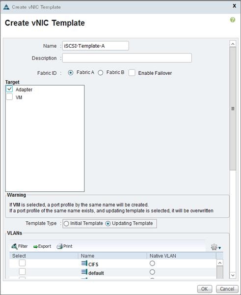
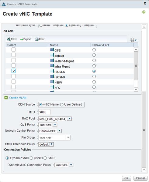
16. Select the LAN tab on the left.
17. Select Policies > root.
18. Right-click vNIC Templates.
19. Select Create vNIC Template.
20. Enter iSCSI-Template-B as the vNIC template name.
21. Select Fabric B. Do not select the Enable Failover checkbox.
22. Under Target, make sure that the VM checkbox is not selected.
23. Select Updating Template for Template Type.
24. Under VLANs, select iSCSI-B.
25. Set iSCSI-B as the native VLAN.
26. Under MTU, enter 9000.
27. From the MAC Pool list, select MAC_Pool_B.
28. From the Network Control Policy list, select Enable-CDP.
29. Click OK to complete creating the vNIC template.
30. Click OK.
Create Boot Policies
This procedure applies to a Cisco UCS environment in which two iSCSI logical interfaces (LIFs) are on cluster node 1 (iscsi lif01a and iscsi lif01b) and two iSCSI LIFs are on cluster node 2 (iscsi lif02a and iscsi lif02b). One boot policy is configured in this procedure. This policy configures the primary target to be iscsi_lif01a.
To create boot policies for the Cisco UCS environment, complete the following steps:
1. In Cisco UCS Manager, click the Servers tab in the navigation pane.
2. Select Policies > root.
3. Right-click Boot Policies.
4. Select Create Boot Policy.
5. Enter Boot-iSCSI as the name of the boot policy.
6. Optional: Enter a description for the boot policy.
7. Keep the Reboot on Boot Order Change option cleared.
8. Expand the Local Devices drop-down menu and select Add Remote CD/DVD.
9. Expand the iSCSI vNICs section and select Add iSCSI Boot.
10. In the Add iSCSI Boot dialog box, enter iSCSI-A-vNIC.
11. Click OK.
12. Select Add iSCSI Boot.
13. In the Add iSCSI Boot dialog box, enter iSCSI-B-vNIC.
14. Click OK.
15. Click OK to save the boot policy. Click OK to close the Boot Policy window.
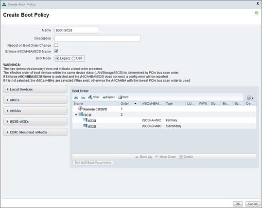
Create Service Profile Templates
In this procedure, one service profile template for Infrastructure ESXi hosts is created for fabric A boot.
To create the service profile template, complete the following steps:
1. In Cisco UCS Manager, click the Servers tab in the navigation pane.
2. Select Service Profile Templates > root.
3. Right-click root.
4. Select Create Service Profile Template to open the Create Service Profile Template wizard.
5. Enter VM-Host-Template as the name of the service profile template. This service profile template is configured to boot from storage node 1 on fabric A.
6. Select the “Updating Template” option.
7. Under UUID, select UUID_Pool as the UUID pool.
8. Click Next.
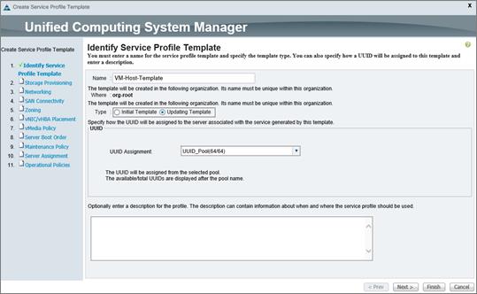
Configure Storage Provisioning
To configure the storage provisioning, complete the following steps:
1. If you have servers with no physical disks, select the iSCSI-Boot Local Storage Policy. Otherwise, select the default Local Storage Policy.
2. Click Next.
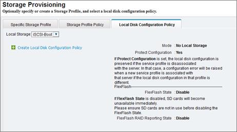
Configure Networking Options
To configure the network options, complete the following steps:
1. Keep the default setting for Dynamic vNIC Connection Policy.
2. Select the “Expert” option to configure the LAN connectivity.
3. Click the upper Add button to add a vNIC to the template.
4. In the Create vNIC dialog box, enter vNIC-A as the name of the vNIC.
5. Select the Use vNIC Template checkbox.
6. In the vNIC Template list, select vNIC-Template-A.
7. In the Adapter Policy list, select VMWare.
8. Click OK to add this vNIC to the template.
9. On the Networking page of the wizard, click the upper Add button to add another vNIC to the template.
10. In the Create vNIC box, enter vNIC-B as the name of the vNIC.
11. Select the Use vNIC Template checkbox.
12. In the vNIC Template list, select vNIC-Template-B.
13. In the Adapter Policy list, select VMWare.
14. Click OK to add the vNIC to the template.
15. Click the upper Add button to add a vNIC to the template.
16. In the Create vNIC dialog box, enter iSCSI-A-vNIC as the name of the vNIC.
17. Select the Use vNIC Template checkbox.
18. In the vNIC Template list, select iSCSI_Template_A.
19. In the Adapter Policy list, select VMWare.
20. Click OK to add this vNIC to the template.
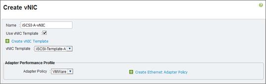
21. Click the upper Add button to add a vNIC to the template.
22. In the Create vNIC dialog box, enter iSCSI-B-vNIC as the name of the vNIC.
23. Select the Use vNIC Template checkbox.
24. In the vNIC Template list, select iSCSI-Template-B.
25. In the Adapter Policy list, select VMWare.
26. Click OK to add this vNIC to the template.
27. Expand the iSCSI vNICs section (if not already expanded).
28. Select IQN_Pool under “Initiator Name Assignment.”
29. Click the lower Add button in the iSCSI vNIC section to define a vNIC.
30. Enter iSCSI-A-vNIC as the name of the vNIC.
31. Select iSCSI-A-vNIC for Overlay vNIC.
32. Set the iSCSI Adapter Policy to default.
33. Set the VLAN to iSCSI-A (native).
34. Leave the MAC Address set to None used by default.
35. Click OK.
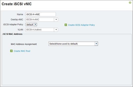
36. Click the lower Add button in the iSCSI vNIC section to define a vNIC.
37. Enter iSCSI-B-vNIC as the name of the vNIC.
38. Set the Overlay vNIC to iSCSI-B-vNIC
39. Set the iSCSI Adapter Policy to default.
40. Set the VLAN to iSCSI-B (native).
41. Leave the MAC Address set to None used by default.
42. Click OK.
43. Review the table in the Networking page to make sure that all vNICs were created.
44. Click Next.
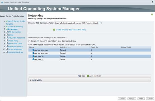
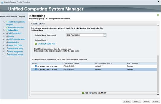
Configure SAN Connectivity
To configure the SAN connectivity, complete the following steps:
1. Select the No vHBAs option for the “How would you like to configure SAN connectivity?” field.
2. Click Next.
Configure Zoning Options
To configure the zoning options, complete the following step:
1. Set no Zoning options and click Next.
Configure vNIC/HBA Placement
To configure vNIC/HBA placement, complete the following steps:
1. In the “Select Placement” list, select the VM-Host placement policy
2. Select vCon1 and assign the vHBAs/vNICs to the virtual network interfaces policy in the following order:
a. vNIC-A: 1
b. vNIC-B: 2
c. iSCSI-vNIC-A: 3
d. iSCSI-vNIC-B: 4
3. Review the table to verify that all vNICs were assigned to the policy in the appropriate order.
4. Click Next.
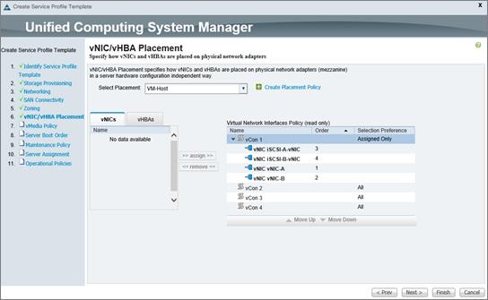
Configure vMedia Policy
To configure vMedia policy, complete the following steps:
1. Do not configure a vMedia Policy at this time.
2. Click Next.
Configure Server Boot Order
To configure the server boot order, complete the following steps:
1. Select Boot-iSCSI for Boot Policy.
2. In the Boot Order pane, select iSCSI-A-vNIC.
3. Click the “Set iSCSI Boot Parameters” button.
4. Leave the “Initiator Name Assignment” dialog box <not set> to use the single Service Profile Initiator Name defined in the previous steps.
5. Set iSCSI_IP_Pool_A as the “Initiator IP Address Policy”.
6. Keep the “iSCSI Static Target Interface” button selected and click the ![]() button at the bottom.
button at the bottom.
7. Log in to the storage cluster management interface and run the following command:
8. iscsi show (admin / Netapp123)
9. Note or copy the iSCSI target name for Infra-SVM.
10. In the Create iSCSI Static Target dialog box, paste the iSCSI target node name from Infra-SVM.
11. Enter the IP address of iSCSI_lif02a for the IPv4 Address field.
12. Click OK to add the iSCSI static target.
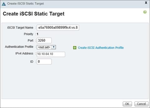
13. Keep the iSCSI Static Target Interface option selected and click the ![]() button.
button.
14. In the Create iSCSI Static Target window, paste the iSCSI target node name from Infra-SVM into the iSCSI Target Name field.
15. Enter the IP address of iscsi_lif01a in the IPv4 Address field.
16. Click OK.
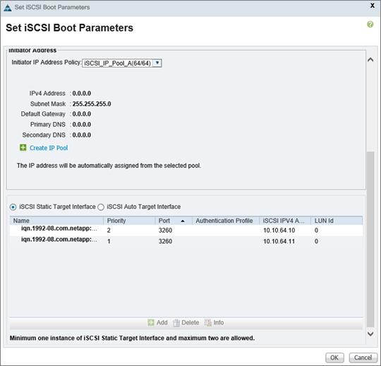
17. Click OK.
18. In the Boot Order pane, select iSCSI-vNIC-B.
19. Click the Set iSCSI Boot Parameters button.
20. In the Set iSCSI Boot Parameters dialog box, set the leave the “Initiator Name Assignment” to <not set>.
21. In the Set iSCSI Boot Parameters dialog box, set the initiator IP address policy to iSCSI_IP_Pool_B.
22. Keep the iSCSI Static Target Interface option selected and click the ![]() button at the bottom right.
button at the bottom right.
23. In the Create iSCSI Static Target window, paste the iSCSI target node name from Infra-SVM into the iSCSI Target Name field (same target name as above).
24. Enter the IP address of iscsi_lif02b in the IPv4 address field.
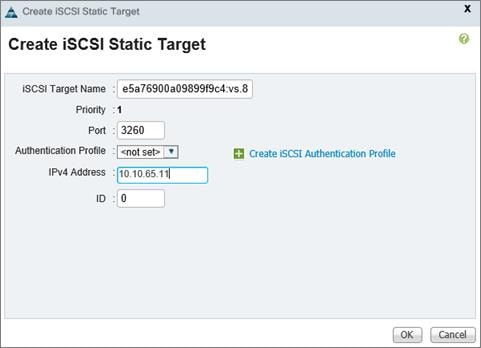
25. Click OK to add the iSCSI static target.
26. Keep the iSCSI Static Target Interface option selected and click the ![]() button.
button.
27. In the Create iSCSI Static Target dialog box, paste the iSCSI target node name from Infra-SVM into the iSCSI Target Name field.
28. Enter the IP address of iscsi_lif01b in the IPv4 Address field.
29. Click OK.
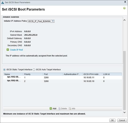
30. Click OK.
31. Review the table to make sure that all boot devices were created and identified. Verify that the boot devices are in the correct boot sequence.
32. Click Next to continue to the next section.
Configure Maintenance Policy
To configure the Maintenance policy, complete the following steps:
1. Select the default Maintenance Policy.
2. Click Next.
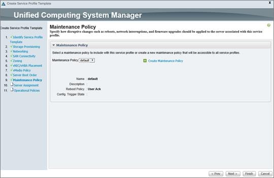
Configure Server Assignment
To configure server assignment, complete the following steps:
1. In the Pool Assignment list, select Server_Pool.
2. Optional: Select a Server Pool Qualification policy.
3. Select Down as the power state to be applied when the profile is associated with the server.
4. Expand Firmware Management at the bottom of the page and select default from the Host Firmware list.
5. Click Next.
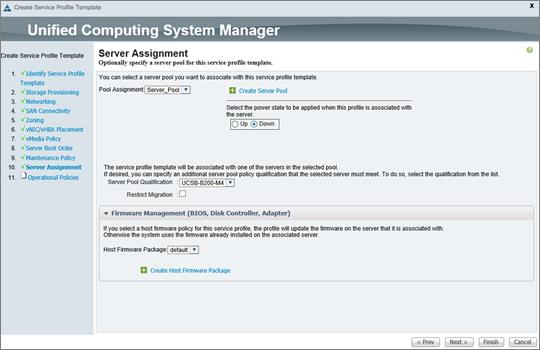
Configure Operational Policies
To configure the operational policies, complete the following steps:
1. In the BIOS Policy list, select B200-M4-BIOS.
2. Expand Power Control Policy Configuration and select No-Power-Cap in the Power Control Policy list.
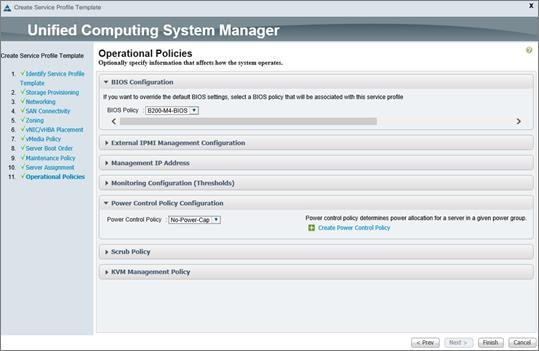
3. Click Finish to create the service profile template.
4. Click OK in the confirmation message.
Create Service Profiles
To create service profiles from the service profile template, complete the following steps:
1. In Cisco UCS Manager, click the Servers tab in the navigation pane.
2. Select Service Profile Templates > root > Service Template VM-Host-Infra-Fabric-A.
3. Right-click VM-Host-Infra-Fabric-A and select Create Service Profiles from Template.
4. Enter VM-Host-0 as the service profile prefix.
5. Enter 1 as “Name Suffix Starting Number.”
6. Enter 2 as the “Number of Instances.”
7. Click OK to create the service profile.
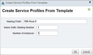
8. Click OK in the confirmation message.
9. Verify the Service Profiles are associated to the blades once the environment has been fully configured.
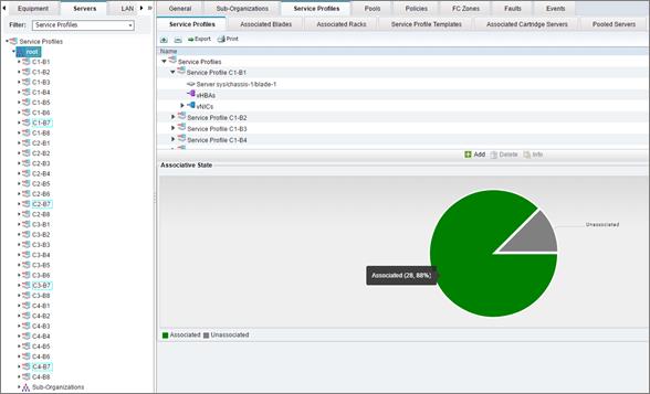
Configuration of AFF8080EX-A with Clustered Data ONTAP
Clustered Data ONTAP Overview
NetApp provides a scalable, unified storage and data management solution. This NetApp solution provides the following benefits:
§ Storage efficiency. Significant cost savings due to multiple levels of storage efficiency on all VMs.
§ Performance. An enhanced user experience with the Virtual Storage Tier (VST) and write I/O optimization that complements NetApp storage efficiency.
§ Operational agility. Enhanced Citrix XenDesktop solution management with tight partner integration.
§ Data protection. Enhanced protection of virtual desktop OS data and user data, with very low overhead in terms of cost and operational data components.
MultiProtocol Support
NFS, iSCSI, and FC perform at a similar level—within a margin of 7 percent. Which protocol you choose is based on your current infrastructure and best practices. However, NetApp makes recommendations for protocol use in clustered Data ONTAP and 7-Mode environments based on the ease of management and cost efficiency. For more information, see TR-3697: Performance Report: Multiprotocol Performance Test of VMware ESX 3.5 on NetApp Storage Systems.
Table 74 shows the preferred storage protocols for the deployment of XenDesktop with Citrix PVS. The virtual desktop solution includes delivery of the OS, any personal applications (instant messaging or Pandora for music for example), corporate apps (MS Office), and the management of user profiles and user data.
Table 74 Storage Protocols for XenDesktop
| Storage component | ESXi | HyperV | Comments |
| vDisk | CIFS SMB 3 or SAN LUN | CIFS SMB 3 | The vDisk is read from storage once and cached in PVS RAM. CIFS SMB 3 provides good performance, reliability, and easy management on vDisk. If you cannot use SMB 3, NetApp recommends using SAN LUN. |
| Write cache | NFS or SAN LUN | CIFS SMB 3 or SAN LUN | NFS is a space-efficient and easily managed protocol. NFS uses thin provisioning by default, which optimizes utilization of available storage. If using SAN LUN, spread the VMs across different LUNs. NetApp recommends 150 to 600 VMs per LUN. For Hyper-V, you can use CIFS SMB 3 or SAN LUN. |
| Personal vDisk | NFS or SAN LUN | CIFS SMB 3 or SAN LUN | As for the write cache, NFS is a space-efficient and easily managed protocol. NFS uses thin provisioning by default, which optimizes utilization of available storage. |
Clustered Data ONTAP
You can group highly available node pairs together to form a scalable cluster. Creating a cluster enables the nodes to pool their resources and distribute work across the cluster while presenting administrators with a single management entity. Clustering also enables continuous service to end users if individual nodes go offline.
A cluster can contain up to 24 nodes for NAS based clusters or up to 10 nodes if it contains a storage virtual machine with an Infinite Volume. A cluster can also contain up to 8 nodes for SAN based clusters (as of Data ONTAP 8.2). Each node in the cluster can view and manage the same volumes as any other node in the cluster. The total file system namespace, which includes all of the volumes and their resultant paths, spans the cluster. If you have a two-node cluster, you must configure cluster high availability (HA). For more information, see the Clustered Data ONTAP High-Availability Configuration Guide.
The nodes in a cluster communicate over a dedicated, physically isolated, dual-fabric and secure Ethernet network. The cluster LIFs on each node in the cluster must be on the same subnet. For information about network management for cluster and nodes, see the Clustered Data ONTAP Network Management Guide. For information about setting up a cluster or joining a node to the cluster, see the Clustered Data ONTAP Software Setup Guide.
Controller AFF80XX Series
For planning the physical location of the storage systems, see the following sections of the Site Requirements Guide:
§ Site Preparation
§ System Connectivity Requirements
§ Circuit Breaker, Power Outlet Balancing, System Cabinet Power Cord Plugs, and Console Pinout Requirements
§ 80xx Series Systems
NetApp Hardware Universe
The NetApp Hardware Universe application lists the supported hardware and software components for specific Data ONTAP versions. It provides configuration information for all of the NetApp storage appliances currently supported by the Data ONTAP software and also a table of component compatibilities. To investigate different storage configurations, complete the following tasks:
1. Confirm that the hardware and software components are supported with the version of Data ONTAP that you plan to install by using the NetApp Hardware Universe (HWU) application at the NetApp Support site.
2. Access the HWU application to view the System Configuration guides. Click the Controllers tab to view the compatibility between Data ONTAP software versions and the NetApp storage appliances with the desired specifications.
3. Alternatively, click Compare Storage Systems to compare components by storage appliance.
Controllers
Follow the physical installation procedures for the controllers. These procedures can be found in the AFF8000 Series product documentation at the NetApp Support site.
Disk Shelves
NetApp storage systems support a wide variety of disk shelves and disk drives. The complete list of disk shelves that are supported with the AFF 80xx is available at the NetApp Support site.
To use SAS disk shelves with NetApp storage controllers, see the SAS Disk Shelves Universal SAS and ACP Cabling Guide for proper cabling guidelines.
Clustered Data ONTAP 8.3.1
This section describes the configuration of clustered Data ONTAP 8.3.2.
Complete the Configuration Worksheet
Before running the setup script, complete the cluster setup worksheet from the Clustered Data ONTAP 8.3 Software Setup Guide. You must have access to the NetApp Support site to open the cluster setup worksheet.
Configure Clustered Data ONTAP Nodes
Before running the setup script, review the configuration worksheets in the Clustered Data ONTAP 8.3 Software Setup Guide. Table 75 lists the information that you need to configure two clustered Data ONTAP nodes. You should customize the cluster detail values with the information that is applicable to your deployment.
Table 75 Clustered Data ONTAP Software Installation Prerequisites
| Cluster Detail | Cluster Detail Value |
| Cluster Node01 IP address | <<var_node01_mgmt_ip>> |
| Cluster Node01 netmask | <<var_node01_mgmt_mask>> |
| Cluster Node01 gateway | <<var_node01_mgmt_gateway>> |
| Cluster Node02 IP address | <<var_node02_mgmt_ip>> |
| Cluster Node02 netmask | <<var_node02_mgmt_mask>> |
| Cluster Node02 gateway | <<var_node02_mgmt_gateway>> |
| Data ONTAP 8.3.1 URL | <<var_url_boot_software>> |
Clustered Data ONTAP 8.3 ADP and Active–Active Configuration
Clustered Data ONTAP 8.3 has several new features that increase optimization for flash technology. Advanced Drive Partitioning (ADP) is a new feature that addresses the storage efficiency challenges of the entry space, increases cache allocation flexibility, and reduces the overall price per GB across AFF8080 platforms. There are three use cases for ADP in this reference architecture; two of these use cases are:
§ Non-dedicated SSDs for the root partition
§ Root partition performance increase by utilizing all SSDs in the aggregate
These use cases are the basis for the storage design in this reference architecture. In this design, the majority of IOPS is offloaded with the Citrix PVS Ram Cache Plus Overflow feature. Therefore, we chose an active–active data partitioning configuration to make sure that the majority of the drive space was available to one storage node to meet capacity requirements. ADP is enabled by default on all AFF systems; therefore, we used ADP in this reference architecture.
Advance Drive Partitioning for SSDs
This use case addresses the usable capacity challenges in the entry space by significantly reducing the root aggregate space allocation. Shared SSDs enable root aggregate to use less space and leave more space to provision data aggregates. Therefore, it improves storage utilization and increases usable and effective capacity on your entry systems.
Each internal SSD is shared by two partitions:
§ The root partition: A smaller partition used to create root aggregates.
§ The data partition: A larger partition used to create data aggregates.
Figure 25 Root and data partition.
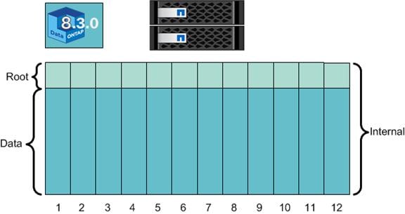
ADP for AFF allows you to create an active–active configuration in a 12 drive entry system, which was previously not possible with Clustered DATA ONTAP (in pre-8.3 versions) due to capacity constraints.
In addition, clustered Data ONTAP requires a dedicated root aggregate, which also helps create capacity challenges for platforms with a limited number of SSDs. However, the primary reason for using a dedicated root aggregate is that hosting user data volumes on the same aggregate as the root volume can increase the risk of the aggregate becoming inconsistent. For more information, see the Storage Subsystem Technical FAQ.
Sharing SSDs into root and data partitioning lets you manage spare capacity efficiently. You can assign partitions for spare capacity instead of dedicating the whole drive. This configuration is particularly useful in an active–passive situation in which the passive node does not serve data and only hosts the root aggregate. Because root aggregates are provisioned using smaller root partitions, you can assign smaller root partitions as spare partitions instead of using the whole drive. This configuration reduces spare-capacity overhead.
Each partitioned SSD can be shared with up to two nodes and two aggregates (a data aggregate and a root aggregate) within an HA pair. There are some trade-offs to sharing an SSD, including a lack of fault isolation and performance isolation. For example, an internal drive failure can affect the root aggregate and the data aggregate. Therefore, NetApp RAID DP® data protection technology is used to increase resiliency and enable best practices. Moreover, you can have RAID DP on both the root aggregates and the data aggregates. With more capacity available in the system, it is easier to assign a spare drive for each node and make the system more resilient.
Root-data partitioning is a compelling feature that makes our entry systems very competitive. Simplicity, traditional aggregate provisioning support, and autopartitioning are some of the main design goals of root-data partitioning.
Storage administrators do not need to learn any new commands to provision aggregates. They do not need to make any choices about partition sizes, which disks gets partitioned, or any other details about partitioning. Therefore, the traditional aggregate provisioning model is preserved. Partitioning happens automatically during system initialization, and Data ONTAP automatically creates root-data partitioning on each internal HDD when the system is zeroing the drives.
Active–Passive Partitioning for SSDs
In the diagram below, Data ONTAP created root aggregates using smaller root partitions, which opens 10 data partitions to create a data aggregate with 20 drives. The data aggregate is a 20 data-partition aggregate composed of 17 data partitions, 2 parity partitions and 1 spare partition. Note that RAID DP is used on both the root aggregates as well as the data aggregate. Spare capacity is allocated based on each aggregate. At the same time, the SSD storage pool uses Raid 4 to take advantage of the most available SSDs and allocates 1 SSD for a spare.
Figure 26 AFF8080 Active–Passive 24-Drive Configuration
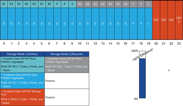
System setup allows you to create active–passive and active–active configurations. Setup automates the process of assigning drives to an active system by letting you select from the following three options:
§ Creating one large data pool (active–passive).
§ Creating two equal pools (active–active).
§ Not performing configuration.
For this reference architecture, we chose one large data pool in an active–passive configuration to meet the capacity requirements. A snapshot of the NetApp system setup utility creating an active–passive configuration follows. You can also create an active–passive configuration from the command line using the following commands:
storage disk removeowner –data true <disk>
storage disk assign –data true –disk <disk> -owner <node_name>
This system is set up in a two-node switchless cluster configuration.
Table 76 Clustered Data ONTAP Software Installation Prerequisites
| Cluster Detail | Cluster Detail Value |
| Cluster node 01 IP address | <<var_node01_mgmt_ip>> |
| Cluster node 01 netmask | <<var_node01_mgmt_mask>> |
| Cluster node 01 gateway | <<var_node01_mgmt_gateway>> |
| Cluster node 02 IP address | <<var_node02_mgmt_ip>> |
| Cluster node 02 netmask | <<var_node02_mgmt_mask>> |
| Cluster node 02 gateway | <<var_node02_mgmt_gateway>> |
| Data ONTAP 8.2.2 URL | <<var_url_boot_software>> |
Node 01
To configure node 01, complete the following steps:
1. Connect to the storage system console port. You should see a Loader-A prompt. However, if the storage system is in a reboot loop, press Ctrl-C to exit the autoboot loop when you see this message:
Starting AUTOBOOT press Ctrl-C to abort
2. Set the boot monitor defaults.
Set-defaults
3. Allow the system to boot up.
autoboot
4. Press Ctrl-C when prompted.
![]() If Data ONTAP 8.3 is not the version of software being booted, continue with the following steps to install new software. If Data ONTAP 8.3 is the version being booted, select option 8 and y to reboot the node and go to step 14.
If Data ONTAP 8.3 is not the version of software being booted, continue with the following steps to install new software. If Data ONTAP 8.3 is the version being booted, select option 8 and y to reboot the node and go to step 14.
5. To install new software, select option 7.
7
6. Answer y to perform an upgrade.
y
7. Select e0M for the network port you want to use for the download.
e0M
8. Select y to reboot now.
y
9. After the reboot, enter the IP address, netmask, and default gateway for e0M in their respective places.
<<var_node01_mgmt_ip>> <<var_node01_mgmt_mask>> <<var_node01_mgmt_gateway>>
10. Enter the URL where the software can be found.
![]() This web server must be pingable.
This web server must be pingable.
<<var_url_boot_software>>
11. Press Enter for the user name, indicating no user name.
12. Enter y to set the newly installed software as the default to be used for subsequent reboots.
y
13. Enter y to reboot the node.
y
![]() When installing new software, the system might perform firmware upgrades to the BIOS and adapter cards, causing reboots and possible stops at the Loader-A prompt. If these actions occur, the system might deviate from this procedure.
When installing new software, the system might perform firmware upgrades to the BIOS and adapter cards, causing reboots and possible stops at the Loader-A prompt. If these actions occur, the system might deviate from this procedure.
14. When you see Press Ctrl-C for Boot Menu, press Ctrl-C.
15. Select option 5 to enter maintenance mode.
5
16. Answer y to enter maintenance mode.
y
17. In this reference architecture, we used 20 SAS drives and 4 SSDs. The 4 SSDs are used for a Flash Pool cache, and the SAS drives are used for the root partition and the data partition. At the maintenance mode prompt, assign 10 of the SAS drives to node 1 and the other 10 SAS drives to node 2. Assign the four SSD drives to node 1. To assign drives, use the following command:
Disk assign disk_name –s system_id
18. After all of the drives are assigned to the storage nodes, halt the system to enter the Loader prompt.
halt
19. At the Loader prompt, reboot the system.
bye
20. When you see Press Ctrl-C for Boot Menu, press Ctrl-C.
21. Select option 4 for a clean configuration and to initialize all disks.
4
22. Answer y to Zero disks, reset config and install a new file system.
y
23. Enter y to erase all data on the disks.
y
![]() The initialization and creation of the root volume can take 90 minutes or more to complete, depending on the number of disks attached. In clustered Data ONTAP 8.3, the system automatically creates a root data partition on 9 drives for node 1 and a root data partition on 9 drives assigned to node 2. One SAS drive on each node is reserved for a spare drive. We create a data partition in active–passive mode to obtain maximum capacity and maximum performance on an AFF8080 with 48 drives. After initialization is complete, the storage system reboots. You can continue with node 2 configuration while the disks for node 1 are zeroing.
The initialization and creation of the root volume can take 90 minutes or more to complete, depending on the number of disks attached. In clustered Data ONTAP 8.3, the system automatically creates a root data partition on 9 drives for node 1 and a root data partition on 9 drives assigned to node 2. One SAS drive on each node is reserved for a spare drive. We create a data partition in active–passive mode to obtain maximum capacity and maximum performance on an AFF8080 with 48 drives. After initialization is complete, the storage system reboots. You can continue with node 2 configuration while the disks for node 1 are zeroing.
Node 2
To configure node 2, complete the following steps:
1. Connect to the storage system console port. You should see a Loader-A prompt. However, if the storage system is in a reboot loop, press Ctrl-C to exit the autoboot loop when you see this message:
Starting AUTOBOOT press Ctrl-C to abort…
2. Set the boot monitor defaults.
set-defaults
3. Allow the system to boot up.
autoboot
4. Press Ctrl-C when prompted.
![]() If Data ONTAP 8.3 is not the version of software being booted, continue with the following steps to install new software. If Data ONTAP 8.3 is the version being booted, select option 8 and y to reboot the node and go to step 14.
If Data ONTAP 8.3 is not the version of software being booted, continue with the following steps to install new software. If Data ONTAP 8.3 is the version being booted, select option 8 and y to reboot the node and go to step 14.
5. To install new software first, select option 7.
7
6. Answer y to perform a nondisruptive upgrade.
y
7. Select e0M for the network port that you want to use for the download.
e0M
8. Select y to reboot now.
y
9. Enter the IP address, netmask, and default gateway for e0M in their respective places.
<<var_node02_mgmt_ip>> <<var_node02_mgmt_mask>> <<var_node02_mgmt_gateway>>
10. Enter the URL where the software can be found.
![]() This web server must be pingable.
This web server must be pingable.
<<var_url_boot_software>>
11. Press Enter for the user name, indicating no user name.
Enter
12. Select yes to set the newly installed software as the default to be used for subsequent reboots.
y
13. Select y to reboot the node.
y
![]() When installing new software, the system might perform firmware upgrades to the BIOS and adapter cards, causing reboots and possible stops at the Loader-A prompt. If these actions occur, the system might deviate from this procedure.
When installing new software, the system might perform firmware upgrades to the BIOS and adapter cards, causing reboots and possible stops at the Loader-A prompt. If these actions occur, the system might deviate from this procedure.
14. When you see Press Ctrl-C for Boot Menu, press Ctrl–C.
15. Select option 4 for a clean configuration and to initialize all disks.
4
16. Answer y to Zero disks, reset config and install a new file system.
y
17. Enter y to erase all the data on the disks.
y
![]() The initialization and creation of the root volume can take 90 minutes or more to complete, depending on the number of disks attached. When initialization is complete, the storage system reboots.
The initialization and creation of the root volume can take 90 minutes or more to complete, depending on the number of disks attached. When initialization is complete, the storage system reboots.
Node Setup in Clustered Data ONTAP
From a console port program attached to the storage controller A (Node 1) console port, run the node setup script. This script will come up when Data ONTAP 8.3 first boots on a node.
1. Follow these prompts:
Welcome to node setup.
You can enter the following commands at any time:
"help" or "?" - if you want to have a question clarified,
"back" - if you want to change previously answered questions, and
"exit" or "quit" - if you want to quit the setup wizard.
Any changes you made before quitting will be saved.
To accept a default or omit a question, do not enter a value.
This system will send event messages and weekly reports to NetApp Technical
Support.
To disable this feature, enter "autosupport modify -support disable" within 24
hours.
Enabling AutoSupport can significantly speed problem determination and
resolution should a problem occur on your system.
For further information on AutoSupport, see:
http://support.netapp.com/autosupport/
Type yes to confirm and continue {yes}: yes
Enter the node management interface port [e0M]: Enter
Enter the node management interface IP address: <<var_node01_mgmt_ip>>
Enter the node management interface netmask: <<var_node01_mgmt_mask>>
Enter the node management interface default gateway: <<var_node01_mgmt_gateway>>
A node management interface on port e0M with IP address <<var_node01_mgmt_ip>> has been created.
This node has its management address assigned and is ready for cluster setup.
To complete cluster setup after all nodes are ready, download and run the System Setup utility from the NetApp Support Site and use it to discover the configured nodes.
For System Setup, this node's management address is: <<var_node01_mgmt_ip>>.
Alternatively, you can use the "cluster setup" command to configure the cluster.
2. Press Return and login to the node with the admin user ID and no password to get a node command prompt.
::> storage failover modify -mode ha
Mode set to HA. Reboot node to activate HA.
::> system node reboot
Warning: Are you sure you want to reboot node "localhost"? {y|n}: y
3. After reboot, go through the node setup procedure with preassigned values.
Welcome to node setup.
You can enter the following commands at any time:
"help" or "?" - if you want to have a question clarified,
"back" - if you want to change previously answered questions, and
"exit" or "quit" - if you want to quit the setup wizard.
Any changes you made before quitting will be saved.
To accept a default or omit a question, do not enter a value.
Enter the node management interface port [e0M]: Enter
Enter the node management interface IP address [<<var_node01_mgmt_ip>>]: Enter
Enter the node management interface netmask [<<var_node01_mgmt_mask>>]: Enter
Enter the node management interface default gateway [<<var_node01_mgmt_gateway>>]: Enter
This node has its management address assigned and is ready for cluster setup.
To complete cluster setup after all nodes are ready, download and run the System Setup utility from the NetApp Support Site and use it to discover the configured nodes.
For System Setup, this node's management address is: <<var_node01_mgmt_ip>>.
Alternatively, you can use the "cluster setup" command to configure the cluster.
4. Login to the node with the admin user and no password.
5. Repeat this procedure for storage cluster node 2.
Cluster Create in Clustered Data ONTAP
Table 77 Cluster Create in Clustered Data ONTAP Prerequisites
| Cluster Detail | Cluster Detail Value |
| Cluster name | <<var_clustername>> |
| Clustered Data ONTAP base license | <<var_cluster_base_license_key>> |
| Cluster management IP address | <<var_clustermgmt_ip>> |
| Cluster management netmask | <<var_clustermgmt_mask>> |
| Cluster management port | <<var_clustermgmt_port>> |
| Cluster management gateway | <<var_clustermgmt_gateway>> |
| Cluster node01 IP address | <<var_node01_mgmt_ip>> |
| Cluster node01 netmask | <<var_node01_mgmt_mask>> |
| Cluster node01 gateway | <<var_node01_mgmt_gateway>> |
The first node in the cluster performs the cluster create operation. All other nodes perform a cluster join operation. The first node in the cluster is considered node 1.
The Cluster Setup wizard is brought up by typing cluster setup.
cluster setup
Welcome to the cluster setup wizard.
You can enter the following commands at any time:
"help" or "?" - if you want to have a question clarified,
"back" - if you want to change previously answered questions, and
"exit" or "quit" - if you want to quit the cluster setup wizard.
Any changes you made before quitting will be saved.
You can return to cluster setup at any time by typing "cluster setup".
To accept a default or omit a question, do not enter a value.
Do you want to create a new cluster or join an existing cluster? {create, join}:
![]() If a login prompt appears instead of the Cluster Setup wizard, start the wizard by logging in with the factory default settings and then enter the cluster setup command.
If a login prompt appears instead of the Cluster Setup wizard, start the wizard by logging in with the factory default settings and then enter the cluster setup command.
To create a new cluster, complete the following steps:
1. Run the following command to create a new cluster:
create
2. Type no for the single node cluster option.
Do you intend for this node to be used as a single node cluster? {yes, no} [no]: no
3. Type no for a cluster network using network switches.
Will the cluster network be configured to use network switches? [yes]:no
4. The system defaults are displayed. Enter yes to use the system defaults. Use the following prompts to configure the cluster ports.
Existing cluster interface configuration found:
Port MTU IP Netmask
e0e 9000 169.254.70.234 255.255.0.0
e0f 9000 169.254.210.105 255.255.0.0
Do you want to use this configuration? {yes, no} [yes]: yes
5. The steps to create a cluster are displayed.
Enter the cluster administrators (username “admin”) password: <<var_password>>
Retype the password: <<var_password>>
Enter the cluster name: <<var_clustername>>
Enter the cluster base license key: <<var_cluster_base_license_key>>
Creating cluster <<var_clustername>>
Enter an additional license key []:<<var_fcp_license>>
The cluster is created. This can take a minute or two.
![]() For this validated architecture, NetApp recommends installing license keys for NetApp SnapRestore® data recovery software, NetApp FlexClone, and the NetApp SnapManager® Suite. Additionally, install all required storage protocol licenses. After you finish entering the license keys, press Enter.
For this validated architecture, NetApp recommends installing license keys for NetApp SnapRestore® data recovery software, NetApp FlexClone, and the NetApp SnapManager® Suite. Additionally, install all required storage protocol licenses. After you finish entering the license keys, press Enter.
Enter the cluster management interface port [e0a]: e0a
Enter the cluster management interface IP address: <<var_clustermgmt_ip>>
Enter the cluster management interface netmask: <<var_clustermgmt_mask>>
Enter the cluster management interface default gateway: <<var_clustermgmt_gateway>>
6. Enter the DNS domain name.
Enter the DNS domain names:<<var_dns_domain_name>>
Enter the name server IP addresses:<<var_nameserver_ip>>
![]() If you have more than one name server IP address, separate the IP addresses with a comma.
If you have more than one name server IP address, separate the IP addresses with a comma.
7. Set up the node.
Where is the controller located []:<<var_node_location>>
Enter the node management interface port [e0M]: e0M
Enter the node management interface IP address [<<var_node01_mgmt_ip>>]: Enter
Enter the node management interface netmask [<<var_node01_mgmt_mask>>]: Enter
Enter the node management interface default gateway [<<var_node01_mgmt_gateway>>]: Enter
![]() The node management interface can be on the same subnet as the cluster management interface, or it can be on a different subnet.
The node management interface can be on the same subnet as the cluster management interface, or it can be on a different subnet.
Cluster Join In Clustered Data ONTAP
Table 78 Cluster Join In Clustered Data ONTAP Prerequisites
| Cluster Detail | Cluster Detail Value |
| Cluster name | <<var_clustername>> |
| Cluster management IP address | <<var_clustermgmt_ip>> |
| Cluster node02 IP address | <<var_node02_mgmt_ip>> |
| Cluster node02 netmask | <<var_node02_mgmt_mask>> |
| Cluster node02 gateway | <<var_node02_mgmt_gateway>> |
The first node in the cluster performs the cluster create operation. All other nodes perform a cluster join operation. The first node in the cluster is considered node 1, and the node joining the cluster in this example is node 2.
To join the cluster, complete the following steps:
1. If prompted, enter admin in the login prompt.
admin
2. The Cluster Setup wizard is brought up by entering cluster setup.
Welcome to the cluster setup wizard.
You can enter the following commands at any time:
"help" or "?" - if you want to have a question clarified,
"back" - if you want to change previously answered questions, and
"exit" or "quit" - if you want to quit the cluster setup wizard.
Any changes you made before quitting will be saved.
You can return to cluster setup at any time by typing "cluster setup".
To accept a default or omit a question, do not enter a value.
Do you want to create a new cluster or join an existing cluster?
{create, join}:
![]() If a login prompt is displayed instead of the Cluster Setup wizard, start the wizard by logging in using the factory default settings, and then enter the cluster setup command.
If a login prompt is displayed instead of the Cluster Setup wizard, start the wizard by logging in using the factory default settings, and then enter the cluster setup command.
3. To join a cluster, run the following command:
join
4. Data ONTAP detects the existing cluster and agrees to join the same cluster. To join the cluster, follow these prompts:
Existing cluster interface configuration found:
Port MTU IP Netmask
e0e 9000 169.254.134.133 255.255.0.0
e0f 9000 169.254.11.51 255.255.0.0
Do you want to use this configuration? {yes, no} [yes]: Enter
5. The steps to join a cluster are displayed.
Enter the name of the cluster you would like to join [<<var_clustername>>]:Enter
![]() The node should find the cluster name. Cluster joining can take a few minutes.
The node should find the cluster name. Cluster joining can take a few minutes.
6. Set up the node.
a. Enter the node management interface port (e0M).
b. Enter the node management interface IP address (<<var_node02_mgmt_ip>>), and press Enter.
c. Enter the node management interface netmask (<<var_node02_netmask>>) and press Enter.
d. Enter the node management interface default gateway (<<var_node02_gw>>) and press Enter.
![]() The node management interface can be on the same subnet as the cluster management interface, or it can be on a different subnet.
The node management interface can be on the same subnet as the cluster management interface, or it can be on a different subnet.
Log in to the Cluster
Open either an SSH connection to the cluster IP or host name and log in to the admin user with the password you provided earlier.
Zero All Spare Disks
To zero all spare disks in the cluster, run the following command:
disk zerospares
![]() Disk autoassign assigns half of the connected disks to each node in the HA pair. If a different disk assignment is required, disk autoassignment must be disabled on both nodes in the HA pair by running the disk option modify command. Spare disks can then be moved from one node to another by running the disk removeowner and disk assign commands.
Disk autoassign assigns half of the connected disks to each node in the HA pair. If a different disk assignment is required, disk autoassignment must be disabled on both nodes in the HA pair by running the disk option modify command. Spare disks can then be moved from one node to another by running the disk removeowner and disk assign commands.
Set Onboard UTA2 Ports Personality
To set the onboard UTA2 port personalities, complete the following steps:
1. To verify the current mode and the current type of the ports, run the ucadmin show command:
clus::> ucadmin show
Current Current Pending Pending Admin
Node Adapter Mode Type Mode Type Status
------------ ------- ------- --------- ------- --------- -----------
clus-01 0c cna target - - online
clus-01 0d cna target - - online
clus-01 0e cna target - - online
clus-01 0f cna target - - online
clus-02 0c cna target - - online
clus-02 0d cna target - - online
clus-02 0e cna target - - online
clus-02 0f cna target - - online
8 entries were displayed.
2. Verify that the current mode of all the ports in use is cna and that the current type is set to target. If this is not the case, then run the following command to change the port personality:
ucadmin modify -node <home node of the port> -adapter <port name> -mode cna -type target
![]() The ports must be offline to run this command. To take an adapter offline, run the fcp adapter modify –node <home node of the port> -adapter <port name> -state down command. Ports must be converted in pairs, for example, 0c and 0d. After completing this task, a reboot is required and the ports must be brought back to the up state.
The ports must be offline to run this command. To take an adapter offline, run the fcp adapter modify –node <home node of the port> -adapter <port name> -state down command. Ports must be converted in pairs, for example, 0c and 0d. After completing this task, a reboot is required and the ports must be brought back to the up state.
Set Auto-Revert on Cluster Management
To set the auto-revert parameter on the cluster management interface, run the following command:
network interface modify –vserver <<var_clustername>> -lif cluster_mgmt –auto-revert true
Failover Groups Management in Clustered Data ONTAP
LIFs and ports have roles; different ports are used for management, storage, data motion, and fault tolerance. Roles include cluster or node management, cluster (for traffic between nodes), intercluster (for SnapMirror replication to a separate cluster), and data. From a solution perspective, data LIFs are further classified by how they are used by servers and applications and whether they reside on private nonroutable networks, corporate internal routable networks, or DMZs.
The NetApp cluster connects to these various networks by using data ports; the data LIFs must use specific sets of ports on each node for traffic to be routed properly. Some LIFs, such as cluster management and data LIFs for NFS and CIFS, can fail over between ports within the same node or between nodes. Therefore, traffic continues without interruption if a cable is unplugged or a node fails. Failover groups are used to control which ports a LIF can fail over to. If failover groups are not set up or are set up incorrectly, LIFs can fail over to a port on the wrong network and cause a loss of connectivity.
| Best Practices |
| § Make all data ports a member of an appropriate failover group. § Associate data LIFs with an appropriate failover group. § To keep network connectivity as standardized as possible, use the same port on each node for the same purpose. |
To create a management port failover group, run the following command:
network interface failover-groups create –vserver <<var_clustername>> -failover-group fg-cluster-mgmt -targets <<var_node01>>:e0a, <<var_node02>>:e0a
Assign Management Failover Group to Cluster Management LIF
To assign the management port failover group to the cluster management LIF, run the following command:
network interface modify –vserver <<var_clustername>> -lif cluster_mgmt –failover-group fg-cluster-mgmt
Failover Groups Node Management in Clustered Data ONTAP
To create a management port failover group, run the following commands:
network interface failover-groups create –vserver <<var_clustername>> -failover-group fg-node-mgmt-01 -targets <<var_node01>>:e0M, <<var_node01>>:e0a
network interface failover-groups create –vserver <<var_clustername>> -failover-group fg-node-mgmt-02 -targets <<var_node02>>:e0M, <<var_node02>>:e0a
Assign Node Management Failover Groups to Node Management LIFs
To assign the management port failover group to the cluster management LIF, run the following commands:
network interface modify -vserver <<var_clustername>> -lif <<var_node01>>_mgmt1 -auto-revert true -failover-group fg-node-mgmt-01
network interface modify –vserver <<var_clustername>> -lif <<var_node02>>_mgmt1 –auto-revert true –failover-group fg-node-mgmt-02
Service Processor Network Interface Setup
To assign a static IPv4 address to the service processor on each node, run the following commands:
system service-processor network modify –node <<var_node01>> -address-family IPv4 –enable true –dhcp none –ip-address <<var_node01_sp_ip>> -netmask <<var_node01_sp_mask>> -gateway <<var_node01_sp_gateway>>
system service-processor network modify –node <<var_node02>> -address-family IPv4 –enable true –dhcp none –ip-address <<var_node02_sp_ip>> -netmask <<var_node02_sp_mask>> -gateway <<var_node02_sp_gateway>>
![]() The service processor IP addresses should be in the same subnet as the node management IP addresses.
The service processor IP addresses should be in the same subnet as the node management IP addresses.
Aggregates in Clustered Data ONTAP
An aggregate is a NetApp virtualization layer that abstracts physical disks from logical datasets that are referred to as flexible volumes. Aggregates are the means by which the total IOPS available to all of the physical disks are pooled as a resource. This design is well suited to meet the needs of an unpredictable, mixed workload.
NetApp recommends using a small aggregate when possible as the root aggregate. In most cases we use a default of three disks for the root aggregate. These root aggregates contains the files required for running and providing GUI management tools for the storage system.
The remaining storage should be placed into a smaller number of larger aggregates. An aggregate can contain multiple RAID groups of disks and the maximum size of an aggregate depends on the storage system model. An aggregate RAID group size for RAID DP can range from 3 to 28 SAS drives.
For VMware hypervisor environments, NetApp recommends using a RAID group size of 16 to 20 SAS drives. Also, NetApp recommends using one large data partition aggregate per controller when possible. For this reference architecture, we created a root data partition aggregate for each AFF8080 storage node and one large data partition aggregate assigned to storage node 1. For more details, see the NetApp configuration limits listed in TR-3838: Storage Subsystem Configuration Guide.
| Best Practices |
| § Use an aggregate RAID group size of 16 to 20 SAS drives. § Create one large data partition aggregate per storage node when possible. Size limitations may require multiple aggregates. |
To create new aggregates, run the following commands:
aggr create -aggregate aggr1_node01 -nodes <<var_node01>> -diskcount <<var_num_disks>>
aggr create -aggregate aggr1_node02 -nodes <<var_node02>> -diskcount <<var_num_disks>>
![]() Retain at least one disk (select the largest disk) in the configuration as a spare. A best practice is to have at least one spare for each disk type and size.
Retain at least one disk (select the largest disk) in the configuration as a spare. A best practice is to have at least one spare for each disk type and size.
![]() Start with five disks initially. You can add disks to an aggregate when additional storage is required. Note that, in this configuration with an AFF8080EX or AFF8080EX-A, you might want to create an aggregate with all but one remaining disk (spare) assigned to the controller.
Start with five disks initially. You can add disks to an aggregate when additional storage is required. Note that, in this configuration with an AFF8080EX or AFF8080EX-A, you might want to create an aggregate with all but one remaining disk (spare) assigned to the controller.
![]() The aggregate cannot be created until disk zeroing completes. Run the aggr show command to display the aggregate creation status. Do not proceed until both aggr1_node1 and aggr1_node2 are online.
The aggregate cannot be created until disk zeroing completes. Run the aggr show command to display the aggregate creation status. Do not proceed until both aggr1_node1 and aggr1_node2 are online.
3. Disable NetApp Snapshot copies for the two recently created data aggregates.
node run <<var_node01>> aggr options aggr1_node01 nosnap on
node run <<var_node02>> aggr options aggr1_node02 nosnap on
4. Delete any existing Snapshot copies for the two data aggregates.
node run <<var_node01>> snap delete –A –a –f aggr1_node01
node run <<var_node02>> snap delete –A –a –f aggr1_node02
5. Rename the root aggregate on node 1 to match the naming convention for this aggregate on node 2.
aggr show
aggr rename –aggregate aggr0 –newname <<var_node01_rootaggrname>>
Storage Failover in Clustered Data ONTAP
To confirm that storage failover is enabled, run the following commands in a failover pair:
1. Verify the status of storage failover.
storage failover show
![]() Both the nodes <<var_node01>> and <<var_node02>> must be capable of performing a takeover. Go to step 3 if the nodes are capable of performing a takeover.
Both the nodes <<var_node01>> and <<var_node02>> must be capable of performing a takeover. Go to step 3 if the nodes are capable of performing a takeover.
2. Enable failover on one of the two nodes.
storage failover modify -node <<var_node01>> -enabled true
![]() Enabling failover on one node enables it for both nodes.
Enabling failover on one node enables it for both nodes.
3. Verify the HA status for the two-node cluster.
![]() This step is not applicable for clusters with more than two nodes.
This step is not applicable for clusters with more than two nodes.
cluster ha show
4. Go to step 6 if HA is configured.
5. Enable HA mode only for the two-node cluster.
![]() Do not run this command for clusters with more than two nodes because doing so can cause problems with failover.
Do not run this command for clusters with more than two nodes because doing so can cause problems with failover.
cluster ha modify -configured true
Do you want to continue? {y|n}: y
6. Verify that hardware assist is correctly configured and, if needed, modify the partner IP address.
storage failover hwassist show
storage failover modify –hwassist-partner-ip <<var_node02_mgmt_ip>> -node <<var_node01>>
storage failover modify –hwassist-partner-ip <<var_node01_mgmt_ip>> -node <<var_node02>>
Disable Flow Control on 10GbE and UTA2 Ports
Flow control mechanisms exist at many different Open Systems Interconnection layers, including but not limited to NFS, TCP window, and Ethernet XON/XOFF. In the context of Ethernet, L2 flow control could not be implemented prior to the introduction of full duplex links because a half-duplex link cannot send and receive traffic simultaneously. 802.3X allows a device on a point-to-point connection experiencing congestion to send a PAUSE frame to temporarily pause all flow of data. A reserved and defined multicast MAC address of 01-80-C2-00-00-01 is used to send the PAUSE frames, which also includes the length of pause requested.
In simple networks, this method may work well. However, larger and larger networks along with more advanced and faster network equipment and software have become available. As a result, technologies such as TCP windowing, increased switch buffering, and end-to-end QoS better address the need for simple flow control throughout the network. Simple Ethernet flow control does not react granularly and fast enough to cope with these environments.
A TCP connection uses the end-to-end connection to determine the window size used. This process can account for bandwidth, buffer space, and round trip time. As congestion or packet loss increases along the entire path, the window size decreases to compensate and thus control the flow.
Contrast this process with PAUSE frames, which work on a point-to-point connection. The switch port or NIC decides when to send a PAUSE frame and for what duration, only taking into account a single link. No upper level protocols are considered. This arrangement can potentially affect TCP performance by introducing artificial delays between hops. TCP might also decrease the window size due to dropped packets. In larger networks, congestion trees might start to form, severely limiting overall network capacity for all attached devices.
For these reasons, NetApp recommends that you disable flow control throughout the network, including on ESXi hosts, UCS servers, Nexus switches and NetApp 10GbE and UTA3 storage ports.
With VMware ESXi 5, flow control is not exposed in the vSphere client GUI. The ethtool command sets flow control on a per-interface basis. There are three options for flow control: autoneg, tx, and rx. The tx option is equivalent to Send on other devices.
| Best Practice |
| § NetApp recommends disabling flow control on all of the 10GbE and UTA2 ports that are connected to external devices. |
To disable flow control, run the following commands:
network port modify -node <<var_node01>> -port e0c,e0d,e0e,e0f -flowcontrol-admin none
Warning: Changing the network port settings will cause a several second interruption in carrier.
Do you want to continue? {y|n}: y
network port modify -node <<var_node02>> -port e0c,e0d,e0e,e0f -flowcontrol-admin none
Warning: Changing the network port settings will cause a several second interruption in carrier.
Do you want to continue? {y|n}: y
network port show –fields flowcontrol-admin
Disable Unused FCoE Ports
Unused switchless cluster interconnect FCoE ports should be disabled. To disable these ports, run the following commands:
fcp adapter modify -node <<var_node01>> -adapter 0e –state down
fcp adapter modify -node <<var_node01>> -adapter 0f –state down
fcp adapter modify -node <<var_node02>> -adapter 0e –state down
fcp adapter modify -node <<var_node02>> -adapter 0f –state down
fcp adapter show –fields state
NTP in Clustered Data ONTAP
To configure time synchronization on the cluster, complete the following steps:
1. Set the time zone for the cluster.
timezone <<var_timezone>>
![]() For example, in the Eastern United States, the time zone is America/New_York.
For example, in the Eastern United States, the time zone is America/New_York.
2. Set the date for the cluster.
date <ccyymmddhhmm.ss>
![]() The format for the date is <[Century][Year][Month][Day][Hour][Minute].[Second]>; for example, 201309081735.17
The format for the date is <[Century][Year][Month][Day][Hour][Minute].[Second]>; for example, 201309081735.17
3. Configure the Network Time Protocol server(s) for the cluster.
cluster time-service ntp server create -server <<var_global_ntp_server_ip>>
Simple Network Management Protocol in Clustered Data ONTAP
To configure the Simple Network Management Protocol (SNMP), complete the following steps:
1. Configure the basic SNMP information, such as the location and the contact. When polled, this information is visible as the sysLocation and sysContact variables in SNMP.
snmp contact <<var_snmp_contact>>
snmp location “<<var_snmp_location>>”
snmp init 1
options snmp.enable on
2. Configure SNMP traps to send to remote hosts, such as a Data Fabric Manager server or another fault management system.
snmp traphost add <<var_oncommand_server_fqdn>>
SNMPv1 in Clustered Data ONTAP
To configure SNMPv1, complete the following step:
1. Set the shared secret plain-text password, which is called a community.
snmp community add ro <<var_snmp_community>>
![]() Use the delete all command with caution. If community strings are used for other monitoring products, the delete all command will remove them.
Use the delete all command with caution. If community strings are used for other monitoring products, the delete all command will remove them.
SNMPv3 in Clustered Data ONTAP
SNMPv3 requires that a user be defined and configured for authentication. To configure SNMPv3, complete the following steps:
1. Create a user called snmpv3user.
security login create -username snmpv3user -authmethod usm -application snmp
2. Enter the authoritative entity's engine ID and select md5 as the authentication protocol.
3. Run the security snmpusers command to view the engine ID.
4. Enter an eight-character minimum-length password for the authentication protocol when prompted.
5. Select des as the privacy protocol.
6. Enter an eight-character minimum-length password for the privacy protocol when prompted.
AutoSupport HTTPS in Clustered Data ONTAP
AutoSupport sends support summary information to NetApp through HTTPS. To configure AutoSupport, run the following command:
system node autosupport modify -node * -state enable –mail-hosts <<var_mailhost>> -transport https -support enable -noteto <<var_storage_admin_email>>
Cisco Discovery Protocol in Clustered Data ONTAP
To enable the Cisco Discovery Protocol (CDP) on the NetApp storage controllers, run the following command:
node run -node * options cdpd.enable on
![]() To be effective, the CDP must also be enabled on directly connected networking equipment such as switches and routers.
To be effective, the CDP must also be enabled on directly connected networking equipment such as switches and routers.
Create Jumbo Frame Maximum Transmission Unit Broadcast Domain in Clustered Data ONTAP
Enable jumbo frames for the data network and the LACP if the switch supports it. NetApp recommends using jumbo frames or a maximum transmission unit (MTU) of 9000 for the data network. Enabling jumbo frames can speed up data traffic and also consumes less CPU bandwidth because fewer frames are sent over the network.
Jumbo frames must be enabled on all physical devices and logical entities from end to end in order to avoid truncation or fragmentation of packets with the maximum size. The link aggregation type will depend largely on the current switching technology used in the environment.
Not all link aggregation implementations are alike or offer the same features. Some implementations only offer failover from one link to another in the event of failure of one link. More complete solutions offer actual aggregation, which allows traffic to flow on two or more links at the same time. There is also the LACP, which allows devices to negotiate the configuration of ports into bundles. For more information regarding the setup of link aggregation with VMware ESXi and clustered Data ONTAP, see TR-4068v2: VMware vSphere 5 on NetApp Clustered Data ONTAP Best Practices.
Figure 27 shows jumbo frame configuration on each network component.
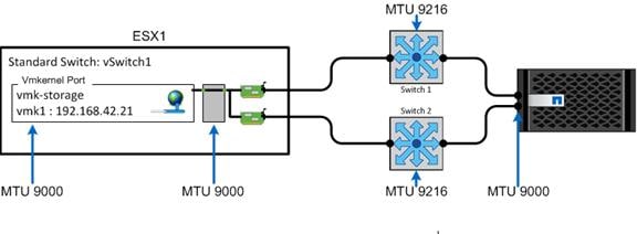
| Best Practice |
| § NetApp recommends using jumbo frames or an MTU of 9000 for the data network. |
To create a data broadcast domain with an MTU of 9000, run the following command:
broadcast-domain create -broadcast-domain Data -mtu 9000
Move 10 GE Data Ports to Data Broadcast Domain
To move the 10 GE data ports to the data broadcast domain, run the following commands:
broadcast-domain remove-ports -broadcast-domain Default -ports <<var_node01>>:e0c, <<var_node01>>:e0d,<<var_node02>>:e0c,<<var_node02>>:e0d
broadcast-domain add-ports -broadcast-domain Data -ports <<var_node01>>:e0c,<<var_node01>>:e0d, <<var_node02>>:e0c,<<var_node02>>:e0d
broadcast-domain show
network port show –fields mtu
Configuring Boot from iSCSI on NetApp AFF8080EX-A
This section describes the configuration of a NetApp AFF8080EX-A storage controller so that it boots from iSCSI.
Overview of Clustered Data ONTAP Boot from iSCSI
In today’s competitive markets, anything an organization can do to speed information access and secure critical data can mean the difference between success and failure. SANs allow you to consolidate your storage resources while also offering increased performance and operational and resource efficiency. NetApp offers a complete family of unified storage solutions that support both file and block protocols, including iSCSI, FC, FCoE, NFS, and SMB/CIFS. This level of choice allows you to configure your storage according to your specific enterprise requirements.
The NetApp iSCSI solution is composed of hardware, software, and services that enable any organization to consolidate data storage from dispersed systems into a single, high-performance storage environment. This solution improves data availability and application uptime, enables comprehensive data protection, simplifies infrastructure and management, and maximizes existing investments and resources.
An Attractive Alternative to Fibre Channel SANs
Many companies believe that SANs based on FC technology are the only solution available. However, NetApp iSCSI SANs are an effective alternative when FC SANs are unfamiliar or economically unfeasible, yet the data storage consolidation benefits of a SAN remain attractive. The NetApp iSCSI SAN delivers the competitive performance advantages of an FC SAN along with the maturity, ease of use, functionality, and pervasiveness of SCSI, IP networking, and Ethernet technologies. With a NetApp iSCSI SAN, companies can amplify their existing skills and infrastructure and take advantage of IP network assets to build SANs out to the edges of the enterprise.
A Full Family of iSCSI Storage Systems
NetApp iSCSI storage systems include broad set of advanced NetApp features and rely on over two decades of IP-based storage experience. iSCSI protocol support is available on the NetApp FAS2500 and FAS8000 series storage systems. The NetApp clustered Data ONTAP operating system enables NetApp iSCSI solutions to scale up or scale out from a few terabytes to over 30PB. Advanced volume and LUN mobility facilitates nondisruptive operations during routine operations, such as maintenance, tech refreshes, and load balancing. You can balance performance by moving LUNs nearly instantaneously between controller nodes and storage media without affecting application uptime.
NetApp storage systems support applications ranging those needed in the remote office to those needed in the data center. A standard Ethernet infrastructure (cables and switches) and iSCSI initiators in servers combine to form the foundation of the NetApp iSCSI SAN solution. This solution fully interoperates and easily integrates with enterprise environments by using both application-specific and general purpose OnCommand management software, including policy-based automation and integration using OnCommand Workflow Automation. In addition, every NetApp solution can incorporate advanced data protection, disaster recovery, and regulatory compliance capabilities.
NetApp iSCSI SANs provide high availability through redundant storage components and multiple redundant data paths, with greater than 99.999% field-measured availability. High availability and accessibility provide excellent support and uptime for applications. In addition, NetApp iSCSI storage systems deliver exceptional performance with Gigabit Ethernet (GbE) and 10GbE connections. NetApp iSCSI storage can cover a broad range of scale and cost and deliver network storage dependability, performance, and functionality to your enterprise.
iSCSI Initiators
To complete a network storage architecture that uses iSCSI, the host server must run an iSCSI initiator that is either a software initiator with an Ethernet adapter or a dedicated iSCSI HBA. The initiator is analogous to an NFS client in a NAS solution or an FCP worldwide name initiator in an FC SAN solution. NetApp supports iSCSI software initiators from the most popular OS vendors, including Microsoft Windows (2003, 2008, 2012, and Hyper-V), VMware ESX, Novell NetWare, Linux (RHEL, SLES, and OEL), IBM AIX, HP-UX, and Oracle Solaris. Multiple iSCSI hardware initiators are also qualified for use with NetApp iSCSI storage systems.
iSCSI Multipath I/O
Multipath I/O provides multiple paths from a server to a storage array and protects against hardware failures cables, switches, HBAs, and so on. Furthermore, multipath I/O can provide higher performance by using the aggregate performance of multiple connections. When one path or connection becomes unavailable, the multipath software automatically shifts the load to one of the other available paths.
NetApp iSCSI systems support multiple types of multipath I/O, both native to the host operating systems and vendor-specific (Data ONTAP Device Specific Module (DSM). Data ONTAP DSM is designed to work with Windows operating systems, including Hyper-V. In addition to failover and link aggregation functionality, Data ONTAP DSM offers advanced features such as least queue depth; active-active load balancing; and the ability to use FCP, FCoE, and iSCSI to communicate with a LUN at the same time (multiprotocol).
Security
Secure storage is increasingly important as the storage of business-critical data, personal data, and customer data increases. NetApp iSCSI storage systems offer many security-related options that allow compliance with corporate security policies. NetApp recommends that you use secure iSCSI administration methods for Data ONTAP, including host authentication (CHAP), private network (physical and VLAN zoning), array LUN masking, IPsec (optional), and key management (optional).
iSCSI Boot from SAN
One of the benefits of shared storage is the ability to consolidate and more effectively allocate storage to each attached server. This benefit also extends to the boot volume. Instead of requiring a boot disk drive (or two for redundancy) at the host, remote boot allows the host to boot from a volume on the shared network storage. The benefits of this approach include improved boot performance by striping the boot volume over more spindles and lower cost by reducing disks at the host. Benefits also include redundancy protection of boot images, simplified software management, rapid server deployment, and improved space efficiency with the use of volume cloning.
iSCSI boot is a process whereby the operating system is initialized from a storage disk array across a storage area network (SAN) rather than from the locally attached hard disk drive. The NetApp approach is more cost-effective and delivers the benefits of any SAN, including better manageability, higher availability, and lower cost of ownership. This approach also removes the high acquisition costs usually associated with deploying SANs by combining these networking and storage functions into a single controller device.
Servers equipped with standard Gigabit network adapters can now connect to SANs with complete iSCSI functionality, including boot capabilities under Windows. This technology eliminates the high up-front acquisition costs of adding storage networking to a server because you do not need to purchase a server with a separate HBA controller preinstalled. In the past, IT professionals had to purchase separate controllers to perform simultaneous data and storage networking functions. Now you purchase a server equipped with a standard network adapter capable of iSCSI software boot that is designed to provide both functions in a single network device.
iSCSI software boot performs the following steps:
1. The system starts up by using the flashed iSCSI firmware on the network adapter for performing remote boot.
2. The iSCSI firmware has the following stacks, which are initiated during the boot phase to establish session with the iSCSI target (storage) and obtain LUN information over the TCP/IP network:
a. The iSCSI stack. built into the firmware to carry SCSI commands over the TCP/IP network. In the initial boot phase, it uses information supplied in the configuration. For example, the initiator/target IP address, the LUN ID, and so on are used to establish the iSCSI session that is required for booting from the storage.
b. The TCP/IP stack. The medium that carries iSCSI packets between the initiator and the target. This stack is a connection-oriented protocol.
3. The system BIOS comes up and contacts the Dynamic Host Configuration Protocol for the IP address, gateway, iSCSI target name, LUN ID, and so on.
4. The BIOS logs into iSCSI target and transfers off to the BIOS boot loader code.
5. The BIOS boot loader code reads the first sector of the disk (the partition table), determines the active partition, and starts loading the NT loader to the system memory.
6. The NT loader reads the kernel and all boot drivers from the iSCSI LUN and transfers control to the Windows OS.
7. Windows starts up and initializes the boot drivers, including the NIC, TCP, and iSCSI drivers.
8. The iSCSI software initiator takes over boot operation and continues to load from the iSCSI disk.
iSCSI LUNs
Volumes containing boot LUNs should be separated from application data to preserve Snapshot data integrity and prevent Snapshot locking when using LUN clones. Even though volumes containing boot LUNs may not require much physical disk space, give the volume enough spindles so that performance is not bound by disk activity. With clustered Data ONTAP 8.3 and later, volumes with boot LUNs can be created on the same aggregate in which the data volumes reside to maximize storage utilization without sacrificing performance.
| Best Practices |
| § NetApp recommends using the best practices for configuring the 10GbE network described in section 6.5 (jumbo frames, flowcontrol none, edge port, and so on). § Create two iSCSI VLANs, one each for iSCSI fabric A and iSCSI fabric B. § Set the iSCSI Boot LUN ID to zero (0). |
Clustered Data ONTAP iSCSI configuration
To configure iSCSI on clustered Data ONTAP, complete the following steps:
1. Add an iSCSI license.
2. Add the iSCSI protocol to the SVM.
3. Enable the iSCSI service.
4. Create iSCSI VLANs.
5. Create iSCSI LIFs.
6. Create volumes.
7. Create the Boot LUNs within the volumes.
8. Create the igroups with the host iSCSI Qualified Name (IQN).
9. Map the LUN to an igroup and set the LUN ID to 0 (LUN masking).
The following commands are needed to complete the steps listed above:
![]() These commands for configuring the storage cluster are listing in Section 6.5 in chronological order. NetApp recommends that you follow the steps in section 6.5 for a complete configuration.
These commands for configuring the storage cluster are listing in Section 6.5 in chronological order. NetApp recommends that you follow the steps in section 6.5 for a complete configuration.
10. The steps required to add a licensed are displayed.
cluster setup
Enter an additional license key []:<<var_fcp_license>>
11. Select the SVM (vserver in the CLI) data protocols to configure, leaving nfs, fcp, and iscsi.
vserver remove-protocols –vserver Infra-SVM -protocols cifs,ndmp
12. To enable the iSCSI service, create the iSCSI service on each SVM. This command also starts the iSCSI service and sets the iSCSI IQN for the SVM.
iscsi create -vserver Infra-SVM
iscsi show
13. Create iSCSI VLAN ports and add them to the Data Broadcast Domain.
network port vlan create –node <<var_node01>> -vlan-name e0c-<<var_iscsi_vlan_A_id>>
network port vlan create –node <<var_node01>> -vlan-name e0d-<<var_iscsi_vlan_B_id>>
network port vlan create –node <<var_node02>> -vlan-name e0c-<<var_iscsi_vlan_A_id>>
network port vlan create –node <<var_node02>> -vlan-name e0d-<<var_iscsi_vlan_B_id>>
broadcast-domain add-ports -broadcast-domain Data -ports <<var_node01>>:e0c-<<var_iscsi_vlan_A_id>>,<<var_node01>>:e0d-<<var_iscsi_vlan_B_id>>,<<var_node02>>:e0c-<<var_iscsi_vlan_A_id>>,<<var_node02>>:e0d-<<var_iscsi_vlan_B_id>>
14. Create four iSCSI LIFs, two on each node.
network interface create -vserver Infra-SVM -lif iscsi_lif01a -role data -data-protocol iscsi -home-node <<var_node01>> -home-port e0c-<<var_iscsi_vlan_A_id>> -address <<var_node01_iscsi_lif01a_ip>> -netmask <<var_node01_iscsi_lif01a_mask>> –status-admin up –failover-policy disabled –firewall-policy data –auto-revert false
network interface create -vserver Infra-SVM -lif iscsi_lif01b -role data -data-protocol iscsi -home-node <<var_node01>> -home-port e0d-<<var_iscsi_vlan_B_id>> -address <<var_node01_iscsi_lif01b_ip>> -netmask <<var_node01_iscsi_lif01b_mask>> –status-admin up –failover-policy disabled –firewall-policy data –auto-revert false
network interface create -vserver Infra-SVM -lif iscsi_lif02a -role data -data-protocol iscsi -home-node <<var_node02>> -home-port e0c-<<var_iscsi_vlan_A_id>> -address <<var_node02_iscsi_lif01a_ip>> -netmask <<var_node02_iscsi_lif01a_mask>> –status-admin up –failover-policy disabled –firewall-policy data –auto-revert false
network interface create -vserver Infra-SVM -lif iscsi_lif02b -role data -data-protocol iscsi -home-node <<var_node02>> -home-port e0d-<<var_iscsi_vlan_B_id>> -address <<var_node02_iscsi_lif01b_ip>> -netmask <<var_node02_iscsi_lif01b_mask>> –status-admin up –failover-policy disabled –firewall-policy data –auto-revert false
network interface show
15. To create a FlexVol volume, you need the following information: the volume’s name and size and the aggregate on which it exists. Create two VMware datastore volumes and a server boot volume. Also, update the SVM root volume load sharing mirrors to make the NFS mounts accessible.
volume create -vserver Infra-SVM -volume infra_datastore_1 -aggregate aggr1_node02 -size 500GB -state online -policy default -junction-path /infra_datastore_1 -space-guarantee none -percent-snapshot-space 0
volume create -vserver Infra-SVM -volume infra_swap -aggregate aggr1_node01 -size 100GB -state online -policy default -junction-path /infra_swap -space-guarantee none -percent-snapshot-space 0 -snapshot-policy none
volume create -vserver Infra-SVM -volume esxi_boot -aggregate aggr1_node01 -size 100GB -state online -policy default -space-guarantee none -percent-snapshot-space 0
snapmirror update-ls-set -source-path //Infra-SVM/rootvol
16. Create the boot LUNs. Repeat this step for the number of iSCSI LUNs required.
lun create -vserver Infra-SVM -volume esxi_boot -lun VM-Host-Infra-01 -size 10GB -ostype vmware -space-reserve disabled
lun create -vserver Infra-SVM -volume esxi_boot -lun VM-Host-Infra-02 -size 10GB -ostype vmware -space-reserve disabled
17. Create the igroups with IQNs.
igroup create -vserver Infra-SVM –igroup Boot01 –protocol iscsi -ostype vmware –portset <portset name> -initiator IQN1, IQN2, IQN3, etc.
18. Map the LUNs to igroups and set LUN ID to zero (0).
Lun map -vserver Infra-SVM –path <path of LUN> -volume <volname> -qtree <qtreename> -lun <lunname> –igroup Boot01 –lun-id 0
Storage Considerations for PVS vDisks
Partition Write Cache File Disk
When you create the PVS write cache file for the VM template, it is a best practice to mount the LUN on an existing Windows Server instance and run DiskPart. To partition a write cache file disk, complete the following steps:
1. Mount the write-cache file disk in Windows Server.
2. Click Start > Run and enter diskpart.
3. Enter list disk.
4. Enter select disk <disk number>.
5. Choose the write-cache file disk number.
6. Enter create partition primary align=32.
7. Unmount the write-cache disk from the Windows Server instance.
8. Attach the disk to the PVS VM template.
Figure 28 shows the procedure to create a partition by using DiskPart.
Figure 28 Partition Write-Cache File Disk using DiskPart
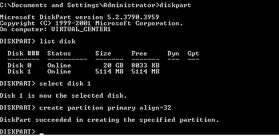
Create Storage Volumes for PVS vDisks
NetApp OnCommand System Manager can be used to set up volumes and LIFs for PVS vDisks. Although LIFs can be created and managed through the command line, this section focuses on the NetApp OnCommand System Manager GUI. Note that System Manager 3.0 or later is required to perform these steps. NetApp recommends creating a new LIF whenever a new volume is created.
In this section, the volume for the PVS write cache and its respective network interface are created.
Create Network Interface
To create the network interface using the OnCommand System Manager, complete the following steps:
1. Log in to clustered Data ONTAP with System Manager.
2. On SVM Hosted_VDI, select the Network Interface tab under Configuration.
3. Click Create to start the Network Interface Create Wizard and then click Next.
4. Enter the name Hosted_VDI_WS for the network interface. Select Data and click Next.
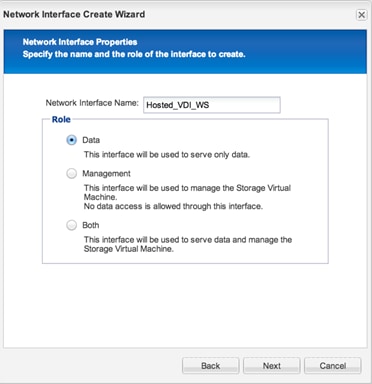
5. Select NFS as the protocol and click Next.
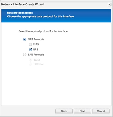
6. Select the home port for the network interface, and enter the corresponding IP Address, Netmask, and Gateway.
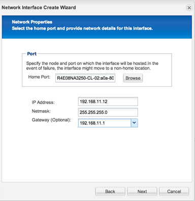
7. On the Summary page, review the details and click Next. The network interface is now available.
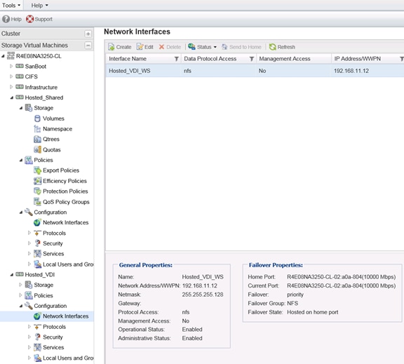
Create Volume for Write-Cache Disks
Use NetApp Virtual Storage Console (VSC) for VMware vSphere to create a volume for the write cache. The VSC applies best practices and makes the provisioning of storage repositories a much simpler operation than performing it manually.
To create a volume for write-cache disks, complete the following steps:
1. To install VSC, build a separate Windows 2012 server and install the VSC vCenter plug-in on the Windows 2012 server.
2. Right-click the host you want to provision as a VMware datastore, and select NetApp VSC > Provision Storage Datastores.
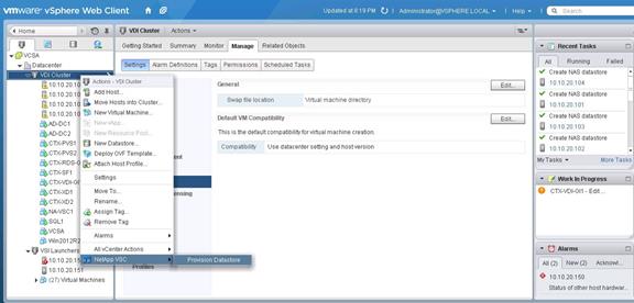
3. Select NetApp and provision datastores.
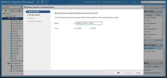
4. Enter the datastore name, choose NFS for the type, and click Next.
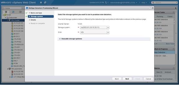
5. Choose the storage system and SVM and click Next.
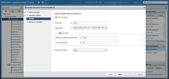
6. Select Thin Provision, enter the size of the volume in GB, choose the aggregate that will contain the volume, select Auto Grow, and set the auto-grow maximum size and the auto-grow increment size in GB. If you have a VMware datastore cluster defined, then choose that cluster and click Next.
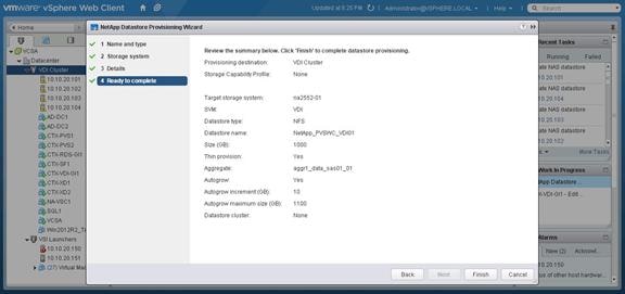
7. Review your input on the Summary screen and, if correct, click Finish. Wait for a moment until the storage volume and VMware datastore are created.
8. You must now launch the NetApp System Manager tool to complete the advance volume settings. System Manager is now a part of clustered Data ONTAP 8.3 resident in the storage nodes. Use your browser and connect to the cluster IP address. The System Manger login screen will appear.
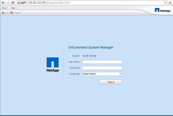
9. Enter the administrative user name and password and click Sign In.

10. When you are signed in, click on SVM > storage > volume menu selection and then highlight the write-cache volume by clicking on the volume name in the right window pane. Then click the Edit menu button.
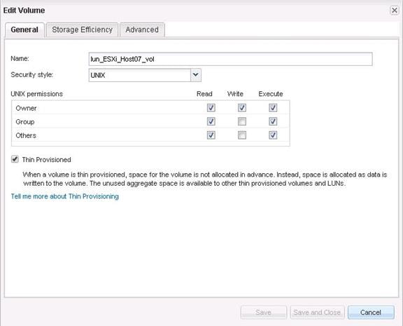
11. Click Storage Efficiency.
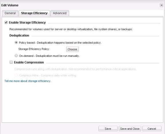
12. Select Enable Storage Efficiency and Policy based – Deduplication Happens Based on the Selected Policy. Click Choose for the storage efficiency policy.
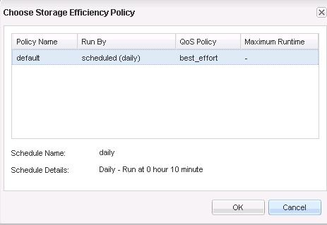
13. Select a policy and click OK.
Deduplication on Write Cache Volumes
Previously, it was NetApp best practice to disable deduplication on volumes that contain write-cache disks. With the advent of NetApp All Flash FAS (flash media) and the new Citrix Ram Cache Plus Overflow feature in XenDesktop 7.7, NetApp recommends enabling deduplication on write-cache volumes. The two primary reasons for the change are the need to reduce the amount of stale data in the write cache disks and the need for capacity reduction.
The Citrix Ram Cache Plus Overflow feature reduces the majority of IOPS from centrally shared storage but still requires the full capacity of the write-cache disks. This creates a requirement for high capacity, low-IOPS write-cache disk volume. This situation takes excellent advantage of the NetApp storage deduplication feature. Storage deduplication is very beneficial in a low-IOPS, high-capacity environment.
Write-cache disks can build up stale data. The write-cache disk cache data is cleared when a VDI desktop is rebooted or deleted. However, in many VDI environments, customers have persistent VDI desktops or VDI desktops that do not get rebooted regularly. Therefore, stale data builds up in the write cache disks. Deduplication reduces the amount of stale data that resides on these disks.
Since capacity is the major requirement in this reference architecture, we enabled deduplication on the write-cache volumes to reduce the amount of capacity required. In addition, write-cache disks may vary in size from user to user. Therefore it is uncertain how much capacity is needed for each user’s write-cache disk.
Another option for conserving capacity is to utilize NetApp volume thin provisioning. Thin provisioning on the write-cache volumes takes the guess work out of allocating capacity for each user’s write-cache disk file and prevents over provisioned in the environment. It is best practice to enable storage thin provisioning on the write-cache volumes.
| Best Practices |
| § Enable NetApp storage deduplication on the write-cache volumes § Enable thin provisioning on the write-cache volumes |
NetApp Storage Configuration for CIFS Shares
CIFS in Cluster Data ONTAP
NetApp is the leader in providing a fully functional CIFS storage server. NetApp has been providing CIFS server functions since SMB1 and NetApp provides support for SMB 2.0, 2.1 and 3.0. The benefit of using the integrated CIFS functionality within the storage array is that it removes need to have the IO processed twice. With a Windows File Server environment, the data is processed at the Windows File Server layer and then passed on to be processed by the storage array. With NetApp’s CIFS functionality, the client maps the share on the NetApp storage cluster directly; therefore, the IO is only processed at the storage array level. In the NetApp CIFS model, the requirement for separate Windows file servers is removed, which then removes the overhead of having the data processed at the Windows File Server.
Clustered Data ONTAP 8.3 brought forward many features to help bring parity with Data ONTAP operating in 7-Mode. Several other new features were introduced as well. Following is a list of all the features, and best practices are outlined where necessary.
Windows File Services Features in Clustered Data ONTAP 8.3
Clustered Data ONTAP 8.3 contains the following new CIFS features:
§ Microsoft Management Console (MMC) support for viewing and managing open files, open sessions, and shares
§ NetBIOS aliases
§ Storage-Level Access Guard (SLAG)
§ Native file-access auditing for user logon and logoff
§ Group Policy object (GPO) security policy support
§ NetApp FPolicy pass-through read support
§ Offloaded data transfer (ODX) enhancements
§ Support for Microsoft Dynamic Access Control (DAC)
Table 79 presents a complete list of CIFS features.
Table 79 8.3 CIFS Features in Clustered Data ONTAP
| CIFS Features |
| Support for Microsoft DAC (Dynamic Access Control) |
| AES 128/256 for CIFS Kerberos authentication |
| ODX direct-copy |
| MMC support for viewing and managing open files and sessions |
| NetBIOS aliases |
| SLAG |
| Native auditing for logon and logoff to shares |
| UNIX character mapping |
| GPO security policy support |
| FPolicy pass-through read support |
| CIFS restrict anonymous capability |
| Control bypass traverse checking |
| CIFS home directory show user command |
| Control of CIFS home directory access for admins |
| Multidomain user mapping |
| LDAP over SSL (start-TLS) |
| Offbox antivirus |
| Separate AD licensing |
| SMB 3.0 , SMB 2.1, and SBM 2.0 |
| Copy offload |
| SMB autolocation |
| BranchCache |
| Local users and groups |
| FSecurity |
| FPolicy |
| Roaming profiles and folder redirection |
| Access-based enumeration (ABE) |
| Offline folders |
| SMB signing |
| Remove VSS |
| File access auditing or file access monitoring |
| Best Practices |
| § Use CIFS shares on the NetApp storage cluster instead of a Windows File Server VM § Use CIFS shares on the NetApp storage cluster for VDI Home directories, VDI profiles, and other VDI CIFS data. |
User Home Data
The first type of user data is end-user data (home directory data). This data is the intellectual property of each company and is directly generated by the end user. In a virtual desktop environment, the home directory data located in a NetApp volume is shared through the CIFS protocol and is mapped as a drive letter in the virtual desktop. This data often requires backup and recovery as well as disaster recovery services. Using a CIFS home directory brings more efficiency in the management and protection of user data. End-user data files should be deduplicated and compressed to achieve storage efficiency and reduce the overall solution cost.
| Best Practices |
| § Use deduplication and compression for end-user data files stored in home directories to achieve storage efficiency. NetApp strongly recommends storing user data on the CIFS home directory in the NetApp storage cluster. § Use Microsoft DFS to manage CIFS shares. NetApp supports client DFS to locate directories and files. § Use the NetApp home directory share feature to minimize the number of shares on the system. § Use SMB3 for home directories. |
User Profile Data
The second type of user data is the user profile (personal data). This data allows the user to have a customized desktop environment when using a non-persistent virtual desktop. User profiles are typically stored in C:\Users on a Microsoft Windows physical machine and can be redirected to a CIFS share for use in a non-persistent, virtual desktop environment.
Many profile management solutions on the market simplify management, improve reliability, and reduce network requirements when compared with standard Windows folder redirection. A profile management solution speeds the migration process from a physical desktop or laptop by first virtualizing the profile and then virtualizing the desktop. This improves login times compared with using folder redirection alone and centralizes the end-user profile for better backup and recovery and disaster recovery of data.
| Best Practices |
| § NetApp recommends using a profile management solution such as Citrix User Profile Management (UPM) or Liquidware Labs ProfileUnity to allow end users to customize their experience while in a nonpersistent desktop environment. § Use redirected folders with a Microsoft GPO. § Use SMB3 for the user profile share. |
Profile Management
Profile management provides an easy, reliable, and high-performance way to manage user personalization settings in virtual or physical Windows OS environments. It requires minimal infrastructure and administration and provides users with fast logons and logoffs. A Windows user profile is a collection of folders, files, registry settings, and configuration settings that define the environment for a user who logs on with a particular user account. These settings can be customized by the user, depending on the administrative configuration. Examples of settings that can be customized are:
§ Desktop settings such as wallpaper and screen saver
§ Shortcuts and start menu settings
§ Internet Explorer favorites and homepage
§ Microsoft Outlook signature
§ Printers
Some user settings and data can be redirected by means of folder redirection. However, these settings are stored within the user profile if folder redirection is not used.
The first stage in planning a profile-management deployment is to decide on a set of policy settings that together form a suitable configuration for your environment and users. The automatic configuration feature simplifies some of this for XenDesktop deployments.
| Best Practices |
| For a faster login: § NetApp recommends a Flash Cache card in 8000 series models § Flash Pools with read cache allocated in the 2500 models § User profile management software to eliminate unnecessary file copying during login |
CIFS Configuration
In clustered Data ONTAP 8.3, you can use Microsoft Management Console (MMC) to create shares. In addition, you can use the NetApp System Manager tool to configure the CIFS server in a NetApp SVM and to configure the CIFS shares as well.
In the section “Section Name”, we showed you how to configure CIFS and add CIFS shares with NetApp CLI commands. In this section, we will use the System Manger GUI tool to perform the same task. To configure CIFS, complete the following steps:
1. To configure CIFS, sign into the System Manager Tool and go to the SVM menu.
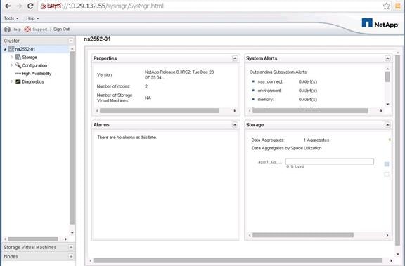
2. Click the SVM menu and then click the SVM that will contain the CIFS volumes and thus require the CIFS configuration.
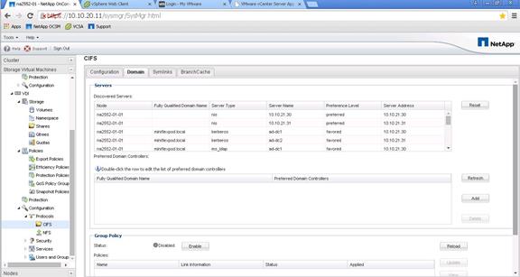
3. In the left pane, select Configuration > Protocols > CIFS.
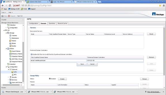
4. In section “name of section”, we added CIFS licenses and enabled the CIFS service. To configure the Preferred Domain Controllers, click the line in the bottom window. Add the preferred DCs IP address and the FQDN and click save. Repeat this step for each DC that is local to your site and that you want to be on your preferred list.
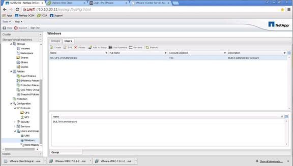
5. Enable the built-in administrator account by selecting Users and Groups in the Configuration menu. Then click Windows. In the right pane, select the local administrator account and click Edit.
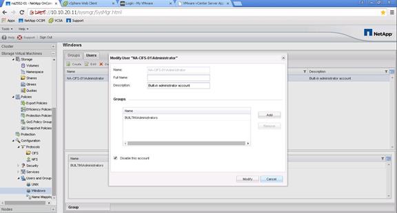
6. Deselect Disable This Account and click Modify.
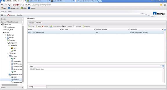
![]() The Account Disabled column should read No.
The Account Disabled column should read No.

7. To configure Windows-to-Unix and Unix-to-Windows name mapping, select Name Mapping within the Users and Groups menu.
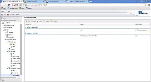
8. Click Add and then add the following:
— Unix to Windows: ID=1, Pattern=root, Replacement=Domain administrator
— Windows to Unix: ID=1, Pattern=Domain administrator, Replacement=root
Create CIFS Shares and Qtrees
Create Qtrees
As a part of the CIFS share design, we chose to utilize NetApp Qtrees to provide quotas at a lower level within the volume. A Qtree is a folder that is created within the NetApp volume and yet is maintained at the storage level, not the hypervisor level. The hypervisor has access to the Qtree, which appears as a normal mount point within the volume. The Qtree folder provides granular quota functions within the volume. A Qtree folder must be created prior to creating the CIFS share because we will export the Qtree folder as the CIFS share.
1. To create a Qtree, sign into the System Manager tool and go to the SVM menu. Then expand the SVM menu and select Storage > Qtrees.
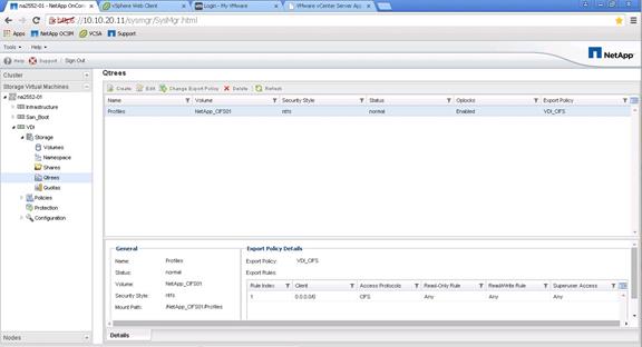
2. In the right pane, click Create to create a Qtree.
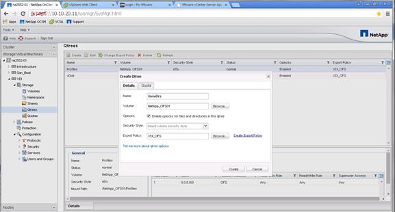
3. Enter the Qtree folder name, chose the storage volume, select Enable Opslocks for Files and Directories in This Qtree, and enter the export policy. You can create the export policy prior to this step or by clicking Create Export Policy. Then click the Quota tab.
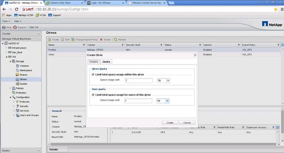
4. Select Limit Total Space Usage Within This Qtree and enter the space usage limit in TB or GB. Then select the Limit Total Space Usage for Users of This Qtree and enter the space usage limit in TB or GB. Click Create.

Create CIFS Shares
There are several tools that can create CIFS shares supported on NetApp storage. Some of the tools that can used to create CIFS shares on NetApp storage are:
§ Microsoft Management Console as of cDOT 8.3
§ The NetApp clustered Data ONTAP CLI
§ NetApp System Manager
For this reference architecture, we are using NetApp System Manager to take advantage of the NetApp User Home Directory Shares feature.
To create CIFS shares, complete the following steps:
1. Within System Manager, select SVM menu, expand the SVM, and select Storage > Shares in the left pane.
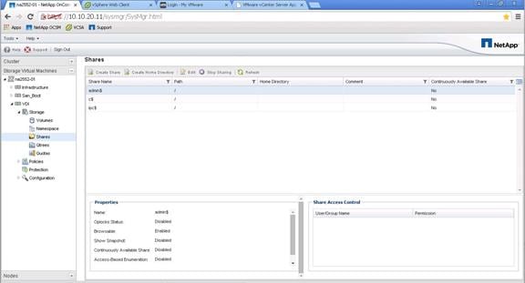
2. Click Create to create the CIFS share.

3. Enter the folder to share (the Qtree path). The CIFS share name is the advertised SMB share name mapped by the VDI clients. Enter a comment and, if needed, select Enable Continuous Availability for Hyper-V and SQL. Click Create.
Selecting Enable Continuous Availability for Hyper-V and SQL enables Microsoft Persistent Handles support on the NetApp SMB3 CIFS share. This feature is only available with SMB3 clients (Windows 2012 Servers) that map the NetApp CIFS share. Therefore, this feature is not available for Windows 2008 or 2003 servers.
Since it is Citrix PVS best practice to install the PVS vDisk on a CIFS share to eliminate the need for multiple copies of the Golden Templates, it is NetApp best practice to activate continuous availability (Persistent Handles) on the PVS vDisk share. Not selecting the option for the PVS vDisk Share may result in a loss of PVS service if a storage controller failover event occurs (one storage node failing over its resources to another storage controller node).
The continuous available option is not needed for normal home directories or profile shares, but it is required for the PVS vDisks.
| Best Practices |
| § Enable Persistent Handles for PVS vDisk CIFS shares by selecting Enable Continuous Availability for Hyper-V and SQL when using System Manager CIFS shares to create the PVS vDisk share. § Do not select the Enable Continuous Availability for Hyper-V and SQL during System Manger CIFS share creation for home directory shares and profile shares. |

4. Deselect Enable Continuous Availability for Hyper-V and SQL for user profile shares and for user home directory shares. Click Create to continue.
Create User Home Directory Shares in Clustered Data ONTAP
NetApp has a feature in its CIFS server called Home Directory Shares (HDS). HDS eliminates the need for many mount points and streamlines user shares. In addition, it allows you to use shares across multiple volumes. When a user logs into the system and the client mounts the home directory folder, HDS has the home directory folder index at the storage level, locates the user’s share folder and mounts the share for the VDI client. This process is very fast and reduces much of the overhead associated with individual user home directory shares. There is one requirement; the user’s home directory folder must be created prior to attempting to map the home directory.
Creating home directory folders can be accomplished with one of several methods. A Microsoft GPO can automatically create a user’s home directory folder. We created our folders in advance with a PowerShell script. The PowerShell script is provided in Appendix B.
To create a user’s home directory folder, complete the following steps:
1. Launch the NetApp System Manager tool and Cluster menu on the left window pane.
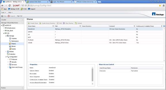
2. In System Manager, expand the SVM menu, select Storage > Shares. Then in the Shares section right window pane, click Create Home Directory.
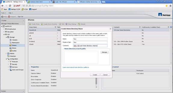
3. Enter %w in the Name field, %w in the Relative Path field, and an informational comment. Under Home Directory Search Paths, click Manage to add a home directory search path.
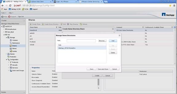
4. Click the Browse button for the Path field and chose the Qtree path where the home directories reside. If you have multiple locations spanning multiple volumes, enter the other volume or qtree paths here. Click Add to add each path and then click Save and Close.
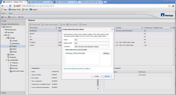
5. Click the Create button to create the user Home Directory Share (HSD).
6. Now test the share by using a Windows client/2012 server and map the HSD to a drive letter (for example, H:\). Keep in mind that the user’s home directory folder must be created first. We created a PowerShell script to create 3000 Home directory folders. This PowerShell script is available in the Appendix.
7. NetApp User Home Directory shares reduce I/O and the number of mount points and eliminate the need to create an individual share for each user. Therefore, it is a best practice to use NetApp User Home Directory shares.
| Best Practices |
| Implement NetApp User Home Directory shares for VDI home directories. |
NetApp AFF8080EX-A All Flash Performance in Practice Storage Efficiencies and Performance with All-Flash FAS Storage Efficiencies Overview
Part of the storage efficiency offerings from NetApp, deduplication provides block-level deduplication within a FlexVol volume or data constituent. NetApp V-Series storage virtualization controllers combined with FlexArray are gateway systems that sit in front of third-party storage and allow NetApp storage efficiency and other features to be used with these systems.
Deduplication removes duplicate blocks and only stores unique blocks in the FlexVol volume or data constituent. Deduplication creates a small amount of additional metadata in the process. Notable features of deduplication include the following:
§ Works with a high degree of granularity at the 4KB block level.
§ Operates on the active file system of the FlexVol volume or data constituent. Any block referenced by a NetApp Snapshot copy is not available until the Snapshot copy is deleted.
§ Is a background process that can be configured to run automatically, run on a schedule, or run manually through the CLI, NetApp System Manager, or NetApp OnCommand Unified Manager. Starting in Data ONTAP 8.3.2, deduplication can be run as an inline process as well as a background process on a per-storage-volume basis (datastore).
§ Is application transparent and therefore can be used to deduplicate data originating from any application that uses the NetApp system.
§ Is enabled and managed by using a simple CLI or GUI such as System Manager or NetApp OnCommand Unified Manager.
NetApp data compression is a software-based solution that provides transparent data compression. Compression can be run inline or post process and can also compress existing data. No application changes are required to use NetApp data compression. The process is enabled and managed by using a simple CLI or GUI such as System Manager or NetApp OnCommand Unified Manager.
Data ONTAP 8.3.1 introduces adaptive compression, an inline compression method that works with I/O blocks of varying sizes. The performance impact from compression is minimal, and enabling adaptive compression in some cases improves overall performance. The compression method available in Data ONTAP 8.3 and earlier is still available and is now called secondary compression.
The following new features were introduced in Data ONTAP 8.3.1:
§ All Flash FAS support. Compression is now officially supported on All Flash FAS series controllers (AFF80XX series controllers).
§ Adaptive compression support.
§ Read performance improvements. Numerous performance optimizations were made to Data ONTAP 8.3.1 compression that enhance read performance and, in particular, random read performance. As a result, Data ONTAP 8.3.1 performance with inline compression is comparable to, or better than, Data ONTAP 8.3.0 performance.
§ Complete Flash Pool integration. Starting with Data ONTAP 8.3.1, Flash Pool can cache both read and write compressed blocks.
§ Subfile cloning support. On adaptive compression-enabled volumes.
§ You can size adaptive compression for AFF configurations using the NetApp sizing tool.
![]() Contact your NetApp sales representative for sizing.
Contact your NetApp sales representative for sizing.
The following new features were introduced in Data ONTAP 8.3.2:
§ Background compression scanner support. Perform in-place conversion of uncompressed data in a volume to a compressed format on All Flash FAS systems.
§ Performance improvement. Compression operations now run in their own domain separate from the data-serving domain, resulting in a performance improvement of up to 15 percent in latency and throughput.
Compression Behavior Based on Configuration
All Flash FAS configuration provides the following benefits:
§ It supports both adaptive and secondary compression.
§ It supports only inline compression.
§ Adaptive inline compression is enabled by default on all new volumes, but only when the effective cluster version is 8.3.1 and all of the nodes in the cluster are on 8.3.1.
§ New volumes have an inline-only storage efficiency policy set by default on SAN-optimized AFF systems.
§ Secondary compression can be enabled manually if required.
§ Compression can be turned on and off at the volume level.
§ A volume can have either adaptive compression or secondary compression but not both. Active file systems and Snapshot copies can have different compression types.
Inline Deduplication
When data is written to the system, the inline operation scans the incoming blocks, creates a fingerprint, and stores the fingerprint in memory. The location where the fingerprints are stored in memory is called the hash store. The hash store is nonpersistent across reboots and volume offline operations.
Because the goal is to dedupe across the blocks that reside in memory and the buffer cache, the hash store is small enough to be stored in memory. The hash store also is very fast when performing insert, lookup, and delete operations. The contents of the hash store are cycled based on a “least recently used” algorithm. This algorithm evicts the least recently used block to make room for the new block whenever the hash store becomes full.
After the fingerprint file is created, the fingerprints are checked for duplicates. When duplicates are found, a byte-by-byte comparison of the blocks in memory is performed to determine whether the in-memory blocks are indeed identical. If the blocks are found to be identical, the block’s pointer is updated to the already existing in-memory data block and the new (duplicate) in-memory data block is released.
No storage metadata overhead is associated with post deduplication in the case of inline deduplication because all the metadata is stored in memory. However, the performance overhead resulting from the entire inline deduplication operation is an increase in latency and a reduction in throughput of less than 1%.
Adaptive Compression
Adaptive compression combines fewer blocks of data into a compression group (8K). The compression group is then compressed and stored as a single block. When a user requests data from this compression group, less time is taken to decompress and provide that data to the user, thereby improving the read performance. In general, adaptive compression is better suited for random workloads. Adaptive compression provides fewer savings relative to secondary compression, but with better performance.
§ How Adaptive Compression Works
NetApp data compression does not compress the entire file as a single contiguous stream of bytes. Doing so would make servicing small reads or overwrites from part of a file prohibitively expensive. This is because the entire file would need to be read from disk and uncompressed before the request could be served. This process would be especially difficult on large files.
To avoid this issue, NetApp data compression compresses a small group of consecutive blocks, known as a compression group. In this way, when a read or an overwrite request comes in, you need to read only a small group of blocks, not the entire file. This process optimizes read and overwrite performance and enables greater scalability in the size of the files being compressed.
§ Compression Groups
The NetApp compression algorithm divides a file into compression groups (CGs). The file must be larger than 8k or it will be skipped for compression and written to disk uncompressed. Compression groups are a maximum of 8K or 32K, depending on the compression type. For secondary compression, the compression group size is 32K; for adaptive compression, the compression group size is 8K.
A compression group contains data from only one file. A single file can be contained within multiple compression groups. If a file is 60k, it is contained within two secondary compression groups. The first is 32k and the second 28k. Similarly, a 15k file is contained within two adaptive compression groups: 8k and 7k.
§ Compressed Writes
NetApp handles compression write requests at the compression group level. Each compression group is compressed separately. The compression group is left uncompressed unless a savings of at least 25 percent (in the case of 32K CGs) or at least 50 percent (in the case of 8K CGs) can be achieved on a per-compression-group basis. This policy optimizes savings while minimizing resource overhead.
Figure 29 Compression Write Request Handling
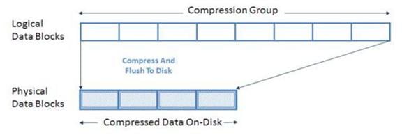
Because compressed blocks contain fewer blocks to be written to disk, compression reduces the number of write I/Os required for each compressed write operation. This reduction does not only lower the data footprint on disk, but it can also decrease the time to complete backups. See the section “Feature Interoperability” for details on volume SnapMirror.
§ Compressed Reads
When a read request comes in, only the compression group (or groups) that contain the requested data is read, not the entire file. This approach optimizes the amount of I/O used to service the request. When reading compressed data, only the required compression group data blocks are transparently decompressed in memory. The data blocks on disk remain compressed. This process creates much less overhead on system resources and read service times. In summary, the NetApp compression algorithm is optimized to reduce overhead for both reads and writes.
When data is sent to the storage system during inline data compression, it is compressed in memory before being written to disk, which reduces the amount of write I/O. This implementation option can affect your write performance and thus should not be used for performance-sensitive environments on HDD configurations without proper testing to understand the impact. The All Flash FAS systems introduced with Data ONTAP 8.3.1 and Flash Pool systems are exceptions. Inline compression can be used for primary workloads on All Flash FAS and Flash Pool systems.
For Flash Pool systems, make sure that the cache size is configured according to Flash Pool best practices. For more information on Flash Pool, see TR-4070: Flash Pool Design and Implementation Guide.
The following are some additional details about inline compression:
§ To provide the fastest throughput, inline compression compresses most new writes but skips more performance-intensive compression operations. An example of a performance-intensive compression operation is a small (<4K) partial file overwrite. Postprocess compression, if enabled, tries to compress any data that was skipped by inline compression.
§ The Incompressible Data Detection (IDD) option is supported only on secondary compression. The enhanced compression algorithm used in Data ONTAP 8.3.1 is intelligent enough to identify incompressible data and return faster. There is no need to use the IDD option on 8.3.1. The option is provided for backward compatibility.
§ IDD is not supported on All Flash FAS configurations.
Configuring Storage Efficiencies for VDI in Clustered Data ONTAP
By default in ONTAP 8.3.2, Inline Deduplication and Adaptive Compression are automatically enabled when creating a volume on all NetApp All Flash-FAS systems. Therefore, your system will have an inline-only efficiency policy enabled by default if it is ordered and shipped to you as an AFF system. On the other hand, you might need to disable storage efficiencies under some circumstances (for example on VM swap volumes). This section shows you how to enable or disable Inline Deduplication and Adaptive Compression on a per volume basis.
It is a NetApp best practice to enable Inline Deduplication and Adaptive Compression by default on all volumes in an All Flash FAS system for performance gains, and doing so increases the longevity of SSDs in the system. On the other hand, there are some exceptions to this best practice in VDI.
| Best Practices |
| § Do not use post deduplication on storage volumes that have Inline Deduplication enabled. § Enable Inline Deduplication and Adaptive Compression on all VDI write-cache volumes. § Enable Inline Deduplication and Adaptive Compression on all CIFS volumes, including the CIFS volumes that contain the Citrix PVS vDisk. § Enable Inline Deduplication and Adaptive Compression on all VM (servers) infrastructure volumes with the exception of volumes dedicated to Swap files or VMSwap files. § Do not enable Inline Deduplication on volumes dedicated for VMSwap files or Swap files. However, you can enable Adaptive Compression on Swap volumes. |
To enable or disable storage efficiencies on All Flash FAS systems, complete the following steps:
1. Login into the NetApp System Manager tool by entering the storage cluster IP address or DNS name in the URL field of a browser. When you have logged in, select Cluster > Storage > Volumes. The following screen appears. Select a volume and click Edit.
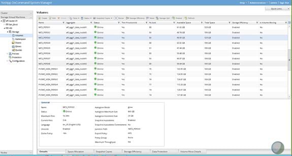
2. Click the Storage Efficiency tab.
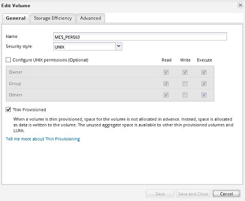
3. If Inline Compression or Adaptive Compression is checked, then these features are enabled. To disable these options, click the box(s) to deselect these options. Click Save and Close to save the selections.
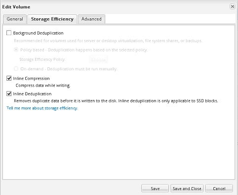
SAN Configuration
A pair of Nexus 9372 switches was used in the configuration to connect between the 10 Gbps iSCSI ports on the NetApp AFF8080EX-A and the 10 GE ports of the Cisco UCS 6248 Fabric Interconnects.
Boot from SAN Benefits
Booting from SAN is another key feature which helps in moving towards stateless computing in which there is no static binding between a physical server and the OS/applications it is tasked to run. The OS is installed on a SAN LUN and boot from SAN policy is applied to the service profile template or the service profile. If the service profile were to be moved to another server, the pwwn of the HBAs and the Boot from SAN (BFS) policy also moves along with it. The new server now takes the same exact character of the old server, providing the true unique stateless nature of the Cisco UCS Blade Server.
The key benefits of booting from the network:
§ Reduce Server Footprints: Boot from SAN alleviates the necessity for each server to have its own direct-attached disk, eliminating internal disks as a potential point of failure. Thin diskless servers also take up less facility space, require less power, and are generally less expensive because they have fewer hardware components.
§ Disaster and Server Failure Recovery: All the boot information and production data stored on a local SAN can be replicated to a SAN at a remote disaster recovery site. If a disaster destroys functionality of the servers at the primary site, the remote site can take over with minimal downtime.
§ Recovery from server failures is simplified in a SAN environment. With the help of snapshots, mirrors of a failed server can be recovered quickly by booting from the original copy of its image. As a result, boot from SAN can greatly reduce the time required for server recovery.
§ High Availability: A typical data center is highly redundant in nature - redundant paths, redundant disks and redundant storage controllers. When operating system images are stored on disks in the SAN, it supports high availability and eliminates the potential for mechanical failure of a local disk.
§ Rapid Redeployment: Businesses that experience temporary high production workloads can take advantage of SAN technologies to clone the boot image and distribute the image to multiple servers for rapid deployment. Such servers may only need to be in production for hours or days and can be readily removed when the production need has been met. Highly efficient deployment of boot images makes temporary server usage a cost effective endeavor.
§ Centralized Image Management: When operating system images are stored on networked disks, all upgrades and fixes can be managed at a centralized location. Changes made to disks in a storage array are readily accessible by each server.
With Boot from SAN, the image resides on a SAN LUN and the server communicates with the SAN through a host bus adapter (HBA). The HBAs BIOS contain the instructions that enable the server to find the boot disk. All FCoE-capable Converged Network Adapter (CNA) cards supported on Cisco UCS B-Series blade servers support Boot from SAN.
After power on self-test (POST), the server hardware component fetches the boot device that is designated as the boot device in the hardware BOIS settings. When the hardware detects the boot device, it follows the regular boot process.
Configuring Boot from SAN Overview
There are three distinct phases during the configuration of Boot from SAN. The high level procedures are:
1. SAN configuration on the Nexus 9372 switches.
2. Storage array host initiator configuration.
3. Cisco UCS configuration of Boot from SAN policy in the service profile.
In each of the following sections, each high-level phase will be discussed.
Configuring Boot from iSCSI on NetApp AFF8080
Clustered Data ONTAP Boot from iSCSI Overview
In today’s competitive markets, anything an organization can do to speed information access and secure critical data can mean the difference between success and failure. Storage area networks (SANs) allow you to consolidate your storage resources while also offering increased performance and operational and resource efficiency. NetApp offers a complete family of unified storage solutions that support both file and block protocols, including iSCSI, FC, FCoE, NFS, and SMB/CIFS, to enable you to configure your storage according to your specific enterprise requirements.
The NetApp iSCSI solution is composed of hardware, software, and services that enable any organization to easily consolidate data storage from dispersed systems into a single, high-performance storage environment. This solution improves data availability and application uptime, enables comprehensive data protection, simplifies infrastructure and management, and maximizes existing investments and resources.
Attractive Alternative to FC SANs
Many companies view SANs that are based on FC technology as their only available solution. NetApp iSCSI SANs are an effective alternative in situations in which FC SANs are unfamiliar or economically unfeasible, and yet the data storage consolidation benefits of a SAN remain attractive. The NetApp iSCSI SAN delivers the competitive performance advantages of an FC SAN along with the maturity, ease, functionality, and pervasiveness of SCSI, IP networking, and Ethernet technologies. With a NetApp iSCSI SAN, companies can amplify their existing skills and infrastructure and take advantage of IP network assets to build SANs out to the edges of the enterprise.
Full Family of iSCSI Storage Systems
NetApp iSCSI storage systems include NetApp’s broad set of advanced features and rely on over two decades of IP-based storage experience. iSCSI protocol support is available on the NetApp FAS2500 and FAS8000 series storage systems. The NetApp clustered Data ONTAP operating system enables NetApp iSCSI solutions to scale up or scale out from a few terabytes (TBs) to over 30PB. Advanced volume and LUN mobility facilitates non-disruptive operations during routine operations, such as maintenance, tech refreshes, and load balancing. You can balance performance by moving LUNs nearly instantaneously between controller nodes and storage media without affecting application uptime.
NetApp storage systems support applications ranging from the remote office to the data center and, when combined with standard Ethernet infrastructure (cables and switches) and iSCSI initiators in servers, can form the foundation of the NetApp iSCSI SAN solution. This solution fully interoperates and easily integrates with enterprise environments by using NetApp OnCommand management software products. These products can be both application-specific and general purpose, including policy-based automation and integration using OnCommand workflow automation. In addition, every NetApp solution is capable of incorporating advanced data protection, disaster recovery, and regulatory compliance capabilities.
NetApp iSCSI SANs provide high availability (HA) through redundant storage components and multiple redundant data paths, with greater than 99.999% field-measured availability. HA and accessibility provide excellent support and uptime for applications. In addition, NetApp iSCSI storage systems deliver exceptional performance with Gigabit Ethernet (GbE) and 10GbE connections. NetApp iSCSI storage can cover a broad range of scale and cost and deliver network storage dependability, performance, and functionality to your enterprise.
iSCSI Boot from SAN
One of the benefits of shared storage is the ability to consolidate and more effectively allocate storage to each attached server. This benefit also extends to the boot volume. Instead of requiring a boot disk drive (or two for redundancy) at the host, remote boot allows the host to boot from a volume on the shared network storage. The benefits of this approach include improved boot performance by striping the boot volume over more spindles, lower cost by reducing disks at the host, redundancy protection of boot images, simplified software management, rapid server deployment, and improved space efficiency with the use of volume cloning.
iSCSI boot is a process whereby the OS is initialized from a storage disk array across a SAN rather than from the locally attached hard disk drive. The NetApp approach is more cost-effective and delivers the same benefits of any SAN, including better manageability, higher availability, and lower cost of ownership, while removing the high acquisition costs usually associated with deploying SANs by combining these networking and storage functions in a single controller device.
Servers equipped with standard Gigabit network adapters, which can be configured to perform iSCSI-offloading chip technology, are now able to connect to SANs with complete iSCSI functionality, including boot capabilities under Windows. This technology eliminates the high, up-front acquisition costs of adding storage networking to a server by allowing IT professionals to avoid having to purchase a server with a separate HBA controller preinstalled. In the past, IT professionals had to purchase separate controllers to perform simultaneous data and storage networking functions rather than purchasing a server equipped with a standard network adapter capable of iSCSI software boot that was designed to provide both functions in a single network device.
iSCSI software boot follows these steps:
1. The system starts up with the flashed iSCSI firmware on the network adapter for performing remote boot.
2. The iSCSI firmware has the following stacks, which are initiated during the boot phase to establish a session with an iSCSI target (storage) and obtain LUN information over the TCP/IP network:
3. The iSCSI stack is built into the firmware to carry SCSI commands over the TCP/IP network. In the initial boot phase, this stack uses information supplied in the configuration. For example, the initiator/target IP address, LUN ID, and so on are used to establish an iSCSI session, which is required for booting from the storage.
4. The TCP/IP stack carries iSCSI packets between the initiator and target and vice versa. It is a connection-oriented protocol.
5. The basic input/output system (BIOS) comes up and contacts the Dynamic Host Configuration Protocol (DHCP) for the IP address, gateway, iSCSI target name, LUN ID, and so on.
6. The BIOS logs into the iSCSI target and transfers the BIOS boot loader code.
7. The BIOS boot loader code reads the first sector of the disk (partition table), determines the active partition, and starts loading the NT loader to the system memory.
8. The NT loader reads the kernel and all boot drivers from the iSCSI LUN and transfers control to the Windows OS.
9. Windows starts up and initializes the boot drivers, including the NIC, TCP, and iSCSI drivers.
10. The iSCSI software initiator takes over boot operation and continues to load from the iSCSI disk.
iSCSI LUNs
Volumes containing boot LUNs should be separated from application data to preserve Snapshot data integrity and prevent Snapshot locking when using LUN clones. Even though volumes containing boot LUNs may not require much physical disk space, provide the volume with enough spindles so that performance is not bound by disk activity. With cluster Data ONTAP 8.3 and later, volumes with boot LUNs can be created on the same aggregate in which the data volumes reside to maximize storage utilization without sacrificing performance.
![]() Volumes containing boot LUNs should be separated from application data to preserve Snapshot data integrity and prevent Snapshot locking when using LUN clones. Even though volumes containing boot LUNs may not require much physical disk space, provide the volume with enough spindles so that performance is not bound by disk activity. With cluster Data ONTAP 8.3 and later, volumes with boot LUNs can be created on the same aggregate in which the data volumes reside to maximize storage utilization without sacrificing performance.
Volumes containing boot LUNs should be separated from application data to preserve Snapshot data integrity and prevent Snapshot locking when using LUN clones. Even though volumes containing boot LUNs may not require much physical disk space, provide the volume with enough spindles so that performance is not bound by disk activity. With cluster Data ONTAP 8.3 and later, volumes with boot LUNs can be created on the same aggregate in which the data volumes reside to maximize storage utilization without sacrificing performance.
| Best Practices |
| § NetApp recommends using the best practices for configuring the 10GbE network in the section “Solution Validation” (jumbo frames, flowcontrol none, edge port) § Create two iSCSI VLANs for iSCSI fabric A and iSCSI fabric B § Set the iSCSI Boot LUNs ID to zero (0) |
Clustered Data ONTAP iSCSI Configuration
To configure iSCSI on clustered Data ONTAP, complete the following steps:
1. Add an iSCSI license.
2. Add the iSCSI protocol to the SVM (also referred to as Vserver in the CLI).
3. Enable the iSCSI service.
4. Create iSCSI VLANs.
5. Create iSCSI LIFs.
6. Create Volumes.
7. Create Boot LUNs within the volumes.
8. Create igroups with the host IQNs.
9. Map LUN to igroup and set LUN ID to 0 (LUN masking).
10. Run the following commands to add a licensed are displayed:
cluster setup
Enter an additional license key []:<<var_fcp_license>>
11. Select the SVM data protocols to configure, leaving nfs, fcp, and iscsi.
vserver remove-protocols –vserver Infra-SVM -protocols cifs,ndmp
12. To enable the iSCSI service, create the iSCSI service on each VSM. This command also starts the iSCSI service and sets the iSCSI Qualified Name (IQN) for the VSM.
iscsi create -vserver Infra-SVM
iscsi show
13. Create iSCSI VLAN ports and add to the Data Broadcast Domain.
network port vlan create –node <<var_node01>> -vlan-name e0c-<<var_iscsi_vlan_A_id>>
network port vlan create –node <<var_node01>> -vlan-name e0d-<<var_iscsi_vlan_B_id>>
network port vlan create –node <<var_node02>> -vlan-name e0c-<<var_iscsi_vlan_A_id>>
network port vlan create –node <<var_node02>> -vlan-name e0d-<<var_iscsi_vlan_B_id>>
broadcast-domain add-ports -broadcast-domain Data -ports <<var_node01>>:e0c-<<var_iscsi_vlan_A_id>>,<<var_node01>>:e0d-<<var_iscsi_vlan_B_id>>,<<var_node02>>:e0c-<<var_iscsi_vlan_A_id>>,<<var_node02>>:e0d-<<var_iscsi_vlan_B_id>>
14. Create four iSCSI LIFs, two on each node.
network interface create -vserver Infra-SVM -lif iscsi_lif01a -role data -data-protocol iscsi -home-node <<var_node01>> -home-port e0c-<<var_iscsi_vlan_A_id>> -address <<var_node01_iscsi_lif01a_ip>> -netmask <<var_node01_iscsi_lif01a_mask>> –status-admin up –failover-policy disabled –firewall-policy data –auto-revert false
network interface create -vserver Infra-SVM -lif iscsi_lif01b -role data -data-protocol iscsi -home-node <<var_node01>> -home-port e0d-<<var_iscsi_vlan_B_id>> -address <<var_node01_iscsi_lif01b_ip>> -netmask <<var_node01_iscsi_lif01b_mask>> –status-admin up –failover-policy disabled –firewall-policy data –auto-revert false
network interface create -vserver Infra-SVM -lif iscsi_lif02a -role data -data-protocol iscsi -home-node <<var_node02>> -home-port e0c-<<var_iscsi_vlan_A_id>> -address <<var_node02_iscsi_lif01a_ip>> -netmask <<var_node02_iscsi_lif01a_mask>> –status-admin up –failover-policy disabled –firewall-policy data –auto-revert false
network interface create -vserver Infra-SVM -lif iscsi_lif02b -role data -data-protocol iscsi -home-node <<var_node02>> -home-port e0d-<<var_iscsi_vlan_B_id>> -address <<var_node02_iscsi_lif01b_ip>> -netmask <<var_node02_iscsi_lif01b_mask>> –status-admin up –failover-policy disabled –firewall-policy data –auto-revert false
network interface show
15. The following information is required to create a FlexVol volume: the volume’s name, size, and the aggregate on which it will exist. Create two VMware datastore volumes and a server boot volume. Also, update the Vserver root volume load sharing mirrors to make the NFS mounts accessible.
volume create -vserver Infra-SVM -volume infra_datastore_1 -aggregate aggr1_node02 -size 500GB -state online -policy default -junction-path /infra_datastore_1 -space-guarantee none -percent-snapshot-space 0
volume create -vserver Infra-SVM -volume infra_swap -aggregate aggr1_node01 -size 100GB -state online -policy default -junction-path /infra_swap -space-guarantee none -percent-snapshot-space 0 -snapshot-policy none
volume create -vserver Infra-SVM -volume esxi_boot -aggregate aggr1_node01 -size 100GB -state online -policy default -space-guarantee none -percent-snapshot-space 0
snapmirror update-ls-set -source-path //Infra-SVM/rootvol
16. Create the boot LUNS. Repeat this step for each of the iSCSI LUNs required.
lun create -vserver Infra-SVM -volume esxi_boot -lun VM-Host-Infra-01 -size 10GB -ostype vmware -space-reserve disabled
lun create -vserver Infra-SVM -volume esxi_boot -lun VM-Host-Infra-02 -size 10GB -ostype vmware -space-reserve disabled
17. Create igroups with IQNs.
igroup create -vserver Infra-SVM –igroup Boot01 –protocol iscsi -ostype vmware –portset <portset name> -initiator IQN1, IQN2, IQN3, etc.
18. Map the LUNs to igroups and set LUN ID to zero (0).
Lun map -vserver Infra-SVM –path <path of LUN> -volume <volname> -qtree <qtreename> -lun <lunname> –igroup Boot01 –lu
Clustered Data ONTAP was introduced to provide more reliability and scalability to the applications and services hosted on Data ONTAP. Windows File Services is one of the key features of clustered Data ONTAP because this software provides services with the Server Message Block (CIFS/SMB) protocol.
SMB 3.0 is a revised version of the SMB 2.x protocol introduced by Microsoft in Windows 8 and Windows Server 2012. SMB 3.0 offers significant enhancements to the SMB protocol in terms of availability, scalability, reliability, and protection.
To set up the CIFS server, you must create an SVM with proper setting for CIFS access, configure DNS on the SVM, create the CIFS server, and, if necessary, set up UNIX user and group name services. For more information on CIFS configuration, see TR-4191: Best Practice Guide for Clustered Data ONTAP 8.2 Windows File Services.
To set up your CIFS server, you must make decisions regarding the SVM, DNS, and CIFS server configurations and record your choices in the planning worksheet prior to creating the configuration. Follow this process for the share called User_Profiles used by Citrix User Profile Manager (UPM).
:> vserver setup
Welcome to the Vserver Setup Wizard, which will lead you through
the steps to create a storage virtual machine that serves data to clients.
Step 1. Create a Vserver.
Enter the Vserver name: CIFS
Choose the Vserver data protocols to be configured {nfs, cifs, fcp, iscsi}:
cifs
Choose the Vserver client services to be configured {ldap, nis, dns}:
dns
Enter the Vserver's root volume aggregate { aggr0_R4E08NA3250_02, DATA_R4E08NA3250_02}
[DATA_R4E08NA3250_02]: DATA_R4E08NA3250_02
Enter the Vserver language setting, or "help" to see all languages [C]: en-us
Enter the Vserver root volume's security style {unix, ntfs, mixed} [unix]:
ntfs
Vserver creation might take some time to finish….Vserver vDisk with language set to C created. The permitted protocols are cifs.
Step 2: Create a data volume
You can type "back", "exit", or "help" at any question.
Do you want to create a data volume? {yes, no} [yes]: yes
Enter the volume name [vol1]: User_Profiles
Enter the name of the aggregate to contain this volume { aggr0_R4E08NA3250_02, DATA_R4E08NA3250_02} [DATA_R4E08NA3250_02]: DATA_R4E08NA3250_02
Enter the volume size: 75GB
Enter the volume junction path [/User_Profiles]:
It can take up to a minute to create a volume…Volume User_Profiles of size 75GB created on aggregate DATA_R4E08NA3250_02 successfully.
Step 3: Create a logical interface.
You can type "back", "exit", or "help" at any question.
Do you want to create a logical interface? {yes, no} [yes]: yes
Enter the LIF name [lif1]: CIFS_User_Profiles
Which protocols can use this interface [cifs]:
Enter the home node { R4E08NA3250-CL-01, R4E08NA3250-CL-02} [R4E08NA3250-CL-02]: R4E08NA3250-CL-02
Enter the home port {a0b, a0b-803, a0b-804} [a0a]:
a0b-803
Enter the IP address: 10.218.241.101
Enter the network mask: 255.255.255.0
Enter the default gateway IP address:
LIF CIFS_User_Profiles on node R4E08NA3250-CL-02, on port a0b-803 with IP address
10.218.241.101 was created.
Do you want to create an additional LIF now? {yes, no} [no]: no
Step 4: Configure DNS (Domain Name Service).
You can type "back", "exit", or "help" at any question.
Do you want to configure DNS? {yes, no} [yes]:
Enter the comma separated DNS domain names: rainier14q1.net
Enter the comma separated DNS server IP addresses: 10.218.241.15
DNS for Vserver CIFS is configured.
Step 5: Configure CIFS.
You can type "back", "exit", or "help" at any question.
Do you want to configure CIFS? {yes, no} [yes]:
Enter the CIFS server name [VDISK]: R4E08NA3250-CL
Enter the Active Directory domain name: rainier14q1.net
In order to create an Active Directory machine account for the CIFS server, you
must supply the name and password of a Windows account with sufficient
privileges to add computers to the "CN=Computers" container within the
"rainier14q1.net" domain.
Enter the user name [administrato]: administrator
Enter the password:
CIFS server "R4E08NA3250-CL" created and successfully joined the domain.
Do you want to share a data volume with CIFS clients? {yes, no} [yes]:
Yes
Enter the CIFS share name [User_Profiles]:
Enter the CIFS share path [/User_Profiles]:
Select the initial level of access that the group "Everyone" has to the share
{No_access, Read, Change, Full_Control} [No_access]: Full_Control
The CIFS share "User_Profiles" created successfully.
Default UNIX users and groups created successfully.
UNIX user "pcuser" set as the default UNIX user for unmapped CIFS users.
Default export policy rule created successfully.
Vserver CIFS, with protocol(s) cifs, and service(s) dns has been
configured successfully.
Creating a CIFS Share for Citrix User Profile Manager (UPM)
Multiple methods to create a CIFS share are supported on NetApp storage. These methods are listed in Section 6.5. For this reference architecture, we used NetApp System Manager to create the profile share. To create the profile share, complete the following steps:
1. Within System Manager, click on the SVM menu, select the SVM, and select Storage > Shares in the left window pane. Click Create Share in the right window pane to create the profile share.

2. After clicking on the create share menu item, the screen below will appear. Enter the profile folder name in the “Folder to Share” field (includes the Qtree path). The CIFS Share name will be an advertised SMB share name for the profile that will be mapped by a Microsoft Group Policy Object (GPO) during login process. It is a best practice to use a Microsoft hidden share by adding a dollar sign ($) at the end of the share name. This prevents users from seeing the share when browsing the network.
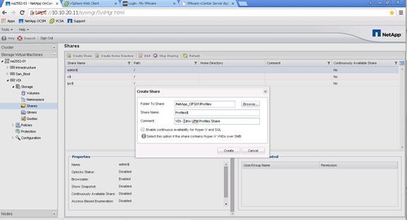
3. Deselect Enable Continuous Availability for Hyer-V and SQL. This check box enables Microsoft Persistent Handles support on the NetApp SMB3 CIFS share. Persistent Handles are not used on normal CIFS shares, but they are used with PVS vDisks. For more information about this option, see section 6.5.
| Best Practice |
| § Use Microsoft hidden shares by adding a dollar sign ($) at the end of the profile share name. |
n-id 0
iSCSI SAN Configuration on Cisco UCS Manager
Refer to section Cisco Unified Computing System Configuration for detailed instructions about configuring iSCSI SAN Boot.
Installing and Configuring VMware ESXi 6.0
This section provides detailed instructions for installing VMware ESXi 6 Update1 in the environment. After the procedures are completed, multiple booted ESXi hosts will be provisioned.
Several methods exist for installing ESXi in a VMware environment. These procedures focus on how to use the built-in keyboard, video, mouse (KVM) console and virtual media features in Cisco UCS Manager to map remote installation media to individual servers and connect to their boot logical unit numbers (LUNs).
Download Cisco Custom Image for ESXi 6 Update1
To download the Cisco Custom Image, complete the following steps:
1. Click the following link vmware login page.
2. Type your email or customer number and the password and then click Log in.
3. Click on the following link CiscoCustomImage6.0.
4. Click Download Now.
5. Save it to your destination folder.
![]() This ESXi 6.0 Update1a Cisco custom image includes the fnic and enic drivers. The versions that are part of this image are: eNIC: 2.1.2.59; fNIC: 1.6.0.12. Newer versions will be installed later in this section.
This ESXi 6.0 Update1a Cisco custom image includes the fnic and enic drivers. The versions that are part of this image are: eNIC: 2.1.2.59; fNIC: 1.6.0.12. Newer versions will be installed later in this section.
KVM Access to Hosts
To log in to the Cisco UCS environment, complete the following steps:
1. Log in to Cisco UCS Manager.
2. The IP KVM enables the administrator to begin the installation of the operating system (OS) through remote media. It is necessary to log in to the Cisco UCS environment to run the IP KVM.
3. Open a Web browser and enter the IP address for the Cisco UCS cluster address. This step launches the Cisco UCS Manager application.
4. Log in to Cisco UCS Manager by using the admin user name and password.
5. From the main menu, click the Servers tab.
6. Select Servers > Service Profiles > root > VM-Host-01.
7. Right-click VM-Host-01 and select KVM Console.
8. Repeat steps for 4-6 for all host servers.
Set Up VMware ESXi Installation
To prepare the server for the OS installation, complete the following steps on each ESXi host:
1. In the KVM window, click the Virtual Media tab.
2. Click Add Image.
3. Browse to the ESXi installer ISO image file and click Open.
4. Select the Mapped checkbox to map the newly added image.
5. Click the KVM tab to monitor the server boot.
6. Boot the server by selecting Boot Server and clicking OK. Then click OK again.
Install ESXi
To install VMware ESXi to the SAN-bootable LUN of the hosts, complete the following steps on each host:
1. On reboot, the machine detects the presence of the ESXi installation media. Select the ESXi installer from the menu that is displayed.
2. After the installer is finished loading, press Enter to continue with the installation.
3. Read and accept the end-user license agreement (EULA). Press F11 to accept and continue.
4. Select the NetApp LUN that was previously set up as the installation disk for ESXi and press Enter to continue with the installation.
5. Select the appropriate keyboard layout and press Enter.
6. Enter and confirm the root password and press Enter.
7. The installer issues a warning that existing partitions will be removed from the volume. Press F11 to continue with the installation.
8. After the installation is complete, clear the Mapped checkbox (located in the Virtual Media tab of the KVM console) to unmap the ESXi installation image.
![]() The ESXi installation image must be unmapped to make sure that the server reboots into ESXi and not into the installer.
The ESXi installation image must be unmapped to make sure that the server reboots into ESXi and not into the installer.
9. The Virtual Media window might issue a warning stating that it is preferable to eject the media from the guest. Because the media cannot be ejected and it is read-only, simply click Yes to unmap the image.
10. From the KVM tab, press Enter to reboot the server.
Set Up Management Networking for ESXi Hosts
Adding a management network for each VMware host is necessary for managing the host. To add a management network for the VMware hosts, complete the following steps on each ESXi host.
To configure the ESXi host with access to the management network, complete the following steps:
1. After the server has finished rebooting, press F2 to customize the system.
2. Log in as root and enter the corresponding password.
3. Select the Configure the Management Network option and press Enter.
4. Select the VLAN (Optional) option and press Enter.
5. Enter the <<var_ib-mgmt_vlan_id>> and press Enter.
6. From the Configure Management Network menu, select IP Configuration and press Enter.
7. Select the Set Static IP Address and Network Configuration option by using the space bar.
8. Enter the IP address for managing the first ESXi host: <<var_vm_host_01_ip>>.
9. Enter the subnet mask for the first ESXi host.
10. Enter the default gateway for the first ESXi host.
11. Press Enter to accept the changes to the IP configuration.
12. Select the IPv6 Configuration option and press Enter.
13. Using the spacebar, unselect Enable IPv6 (restart required) and press Enter.
14. Select the DNS Configuration option and press Enter.
![]() Because the IP address is assigned manually, the DNS information must also be entered manually.
Because the IP address is assigned manually, the DNS information must also be entered manually.
15. Enter the IP address of the primary DNS server.
16. Optional: Enter the IP address of the secondary DNS server.
17. Enter the fully qualified domain name (FQDN) for the first ESXi host.
18. Press Enter to accept the changes to the DNS configuration.
19. Press Esc to exit the Configure Management Network submenu.
20. Press Y to confirm the changes and return to the main menu.
21. The ESXi host reboots. After reboot, press F2 and log back in as root.
22. Select Test Management Network to verify that the management network is set up correctly and press Enter.
23. Press Enter to run the test.
24. Press Enter to exit the window.
25. Press Esc to log out of the VMware console.
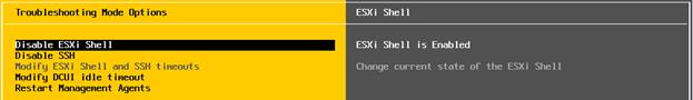
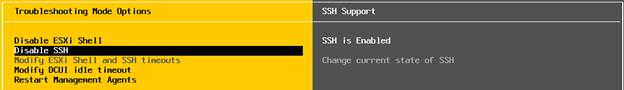
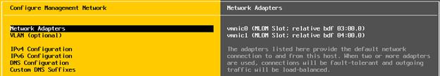
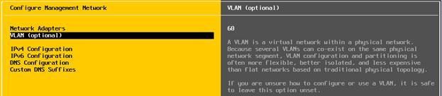
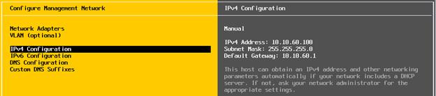
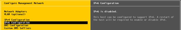
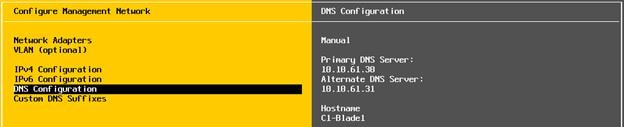
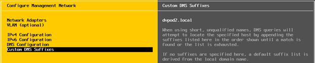
Download VMware vSphere Client and vSphere Remote CLI
To download the VMware vSphere Client, complete the following steps:
1. Open a web browser on the management workstation and navigate to the VM-Host-01 management IP address.
2. Download and install the vSphere Client.
![]() This application is downloaded from the VMware website and Internet access is required on the management workstation.
This application is downloaded from the VMware website and Internet access is required on the management workstation.
Download VMware vSphere CLI 6
To download VMware vSphere CLI 6, complete the following steps:
1. Click the following link VMware vSphere CLI 6.0
2. Select your OS and Click Download.
3. Save it to your destination folder.
4. Run the VMware-vSphere-CLI.exe
5. Click Next.
6. Accept the terms for the license and click Next.
7. Click Next on the Destination Folder screen.
8. Click Install.
9. Click Finish.
![]() Install VMware vSphere CLI 6.0 on the management workstation.
Install VMware vSphere CLI 6.0 on the management workstation.
Log in to VMware ESXi Hosts by using VMware vSphere Client
To log in to the VM-Host-01 ESXi host by using the VMware vSphere Client, complete the following steps:
1. Open the recently downloaded VMware vSphere Client and enter the IP address of VM-Host-01 as the host you are trying to connect to: <<var_vm_host_01_ip>>.
2. Enter root for the user name.
3. Enter the root password.
4. Click Login to connect.
Download Updated Cisco VIC eNIC Drivers
To download the Cisco virtual interface card (VIC) eNIC drivers, complete the following steps:
![]() The eNIC version used in this configuration is 2.3.0.6
The eNIC version used in this configuration is 2.3.0.6
1. Open a Web browser on the management workstation and navigate to:
2. https://my.vmware.com/group/vmware/details?downloadGroup=OEM-ESXI60U1A-CISCO&productId=491
3. Download the eNIC driver bundle.
4. Open the eNIC driver bundle. This bundle includes the VMware driver bundle which will be uploaded to ESXi hosts.
5. Save the location of these driver bundles for uploading to ESXi in the next section.
![]() If the link above has changed, go to www.cisco.com for the latest ISO image of Cisco UCS-related drivers. This ISO will either have the drivers included or may have an HTML file with the location of the latest network drivers.
If the link above has changed, go to www.cisco.com for the latest ISO image of Cisco UCS-related drivers. This ISO will either have the drivers included or may have an HTML file with the location of the latest network drivers.
Load Updated Cisco VIC eNIC Drivers
To install VMware VIC Drivers on the ESXi host servers, complete the following steps:
1. From each vSphere Client, select the host in the inventory.
2. Click the Summary tab to view the environment summary.
3. From Resources > Storage, right-click datastore1 and select Browse Datastore.
4. Click the fourth button and select Upload File.
5. Navigate to the saved location for the downloaded VIC drivers and select fnic_driver_1.6.0.24-3438958.zip.
6. Click Open and Yes to upload the file to datastore1.
7. Click the fourth button and select Upload File.
8. Navigate to the saved location for the downloaded VIC drivers and select enic-2.3.0.6-esxi60-3359058.zip.
9. Click Open and Yes to upload the file to datastore1.
10. Make sure the files have been uploaded to both ESXi hosts.
11. From the management workstation, open the VMware vSphere Remote CLI that was previously installed.
12. At the command prompt, run the following commands to account for each host
![]() To get the host thumbprint, type the command without the –-thumbprint option, then copy and paste the thumbprint into the command.
To get the host thumbprint, type the command without the –-thumbprint option, then copy and paste the thumbprint into the command.
esxcli –s <<var_vm_host_ip>> -u root –p <<var_password>> --thumbprint <host_thumbprint> software vib update -d /vmfs/volumes/datastore1/ enic-2.3.0.6-esxi60-offline_bundle-3359058.zip
Optional fnic update: esxcli –s <<var_vm_host_ip>> -u root –p <<var_password>> --thumbprint <host_thumbprint> software vib update -d /vmfs/volumes/datastore1/fnic_driver_1.6.0.24-offline_bundle-3438958.zip
13. Back in the vSphere Client for each host, right click the host and select Reboot.
14. Click Yes and OK to reboot the host.
15. Log back into each host with vSphere Client.
![]() Verify the enic driver version installed by entering vmkload_mod –s enic at the command prompt.
Verify the enic driver version installed by entering vmkload_mod –s enic at the command prompt.
Set Up VMkernel Ports and Virtual Switch
To set up the VMkernel ports and the virtual switches on the VM-Host-01. ESXi host, complete the following steps:
iSCSI vSwitch and Port Configuration
1. From the vSphere Client, select the host in the inventory.
2. Click the Configuration tab.
3. Click Networking in the Hardware pane.
4. Click Properties on the right side of iScsiBootvSwitch.
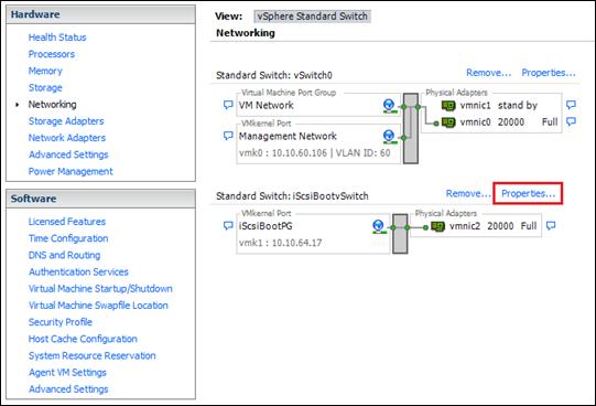
5. Select the vSwitch configuration and click Edit.
6. Change the MTU to 9000.
7. Click OK.
8. Select iScsiBootPG and click Edit.
9. Change the Network Label to VMkernel-iSCSI-A. Leave the VLAN ID set to None.
10. Change the MTU to 9000.
11. Click OK.
12. Click Close.
13. In the vSphere Standard Switch view, click Add Networking.
14. Select VMkernel and click Next.
15. Select Create a vSphere standard switch to create a new vSphere standard switch.
16. Select the check boxes for the network adapter vmnic3.
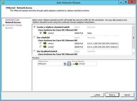
17. Click Next.
18. Change the network label to VMkernel-iSCSI-B. Leave the VLAN ID set to None.
19. Click Next.
20. Enter the IP address and the subnet mask for the iSCSI-B VLAN interface for VM-Host-01.
21. Click Next.
22. Click Finish.
23. On the right side of vSwitch1, click Properties.
24. Select the vSwitch configuration and click Edit.
25. Change the MTU to 9000.
26. Click OK.
27. Select VMkernel-iSCSI-B and click Edit.
28. Change the MTU to 9000.
29. Click OK.
30. Click Close.
Setup iSCSI Multipathing
To setup four iSCSI paths between storage and the ESXi host, complete the following steps on each ESXi host:
1. From the vSphere Client, click Storage Adapters in the Hardware pane.
2. Select the iSCSI Software Adapter and click Properties.
3. Select the Dynamic Discovery tab and click Add.
4. Enter the IP address of iscsi_lif01a.
5. Click OK.
6. Repeat putting in the IP addresses of iscsi_lif01b, iscsi_lif02a and iscsi_lif02b.
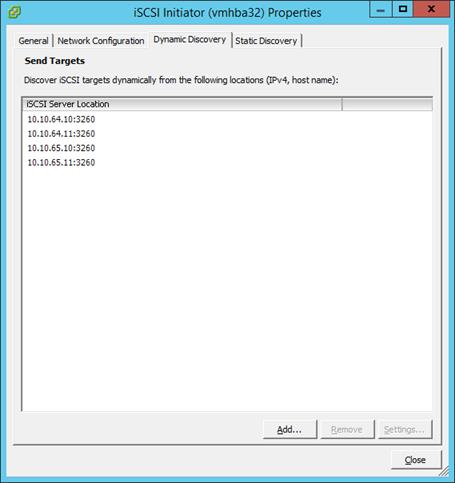
7. Click Close and then click Yes to rescan the host bus adapter.
8. You should now see 4 connected paths in the Details pane.
Data vSwitch Configuration
To configure the data vSwitch, complete the following steps:
1. Click Networking in the Hardware pane.
2. Click Properties on the right side of vSwitch0.
3. Select the vSwitch configuration and click Edit.
4. From the General tab, change the MTU to 9000.
5. From the NIC Teaming tab, select vmnic1 and click Move Up to add the vmnic to the list of active adapters.
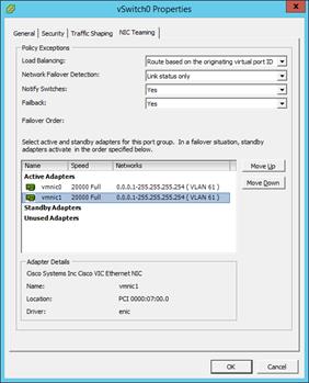
6. Click OK to close the properties for vSwitch0.
7. Select the Management Network configuration and click Edit.
8. Change the network label to VMkernel MGMT and select the Management Traffic checkbox.
9. Click OK to finalize the edits for Management Network.
10. Select the VM Network configuration and click Edit.
11. Change the network label to Infra MGMT and enter <<var_infra-mgmt_vlan_id>> in the VLAN ID (Optional) field.
12. Click OK to finalize the edits for VM Network.
13. Click Add to add a network element.
14. Select VMkernel and click Next.
15. Change the network label to VMkernel NFS and enter <<var_nfs_vlan_id>> in the VLAN ID (Optional) field.
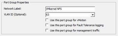
16. Click Next to continue with the NFS VMkernel creation.
17. Enter the IP address <<var_nfs_vlan_id_ip_host-01>> and the subnet mask <<var_nfs_vlan_id_mask_host01>> for the NFS VLAN interface for VM-Host-01.
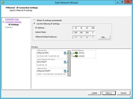
18. Click Next to continue with the NFS VMkernel creation.
19. Click Finish to finalize the creation of the NFS VMkernel interface.
20. Select the VMkernel NFS configuration and click Edit.
21. Change the MTU to 9000.
22. Click OK to finalize the edits for the VMkernel NFS network.
23. Click Add to add a network element.
24. Select VMkernel and click Next.
25. Change the network label to VMkernel vMotion and enter <<var_vmotion_vlan_id>> in the VLAN ID (Optional) field.
26. Select the Use This Port Group for vMotion checkbox.
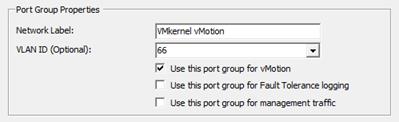
27. Click Next to continue with the vMotion VMkernel creation.
28. Enter the IP address <<var_vmotion_vlan_id_ip_host-01>> and the subnet mask <<var_vmotion_vlan_id_mask_host-01>> for the vMotion VLAN interface for VM-Host-Infra-01.
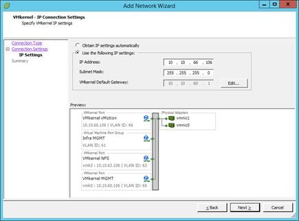
29. Click Next to continue with the vMotion VMkernel creation.
30. Click Finish to finalize the creation of the vMotion VMkernel interface.
31. Select the VMkernel vMotion configuration and click Edit.
32. Change the MTU to 9000.
33. Click OK to finalize the edits for the VMkernel vMotion network.
34. Click Add to add a network element.
35. Select Virtual Machine and click Next.
36. Change the network label to VDI and enter <<var_vmotion_vlan_id>> in the VLAN ID (Optional) field.
37. Click Finish to finalize the creation of the port group.
38. Close the vSwitch0 dialog box to finalize the ESXi host networking setup. The networking for the ESXi host should be similar to the following configuration:
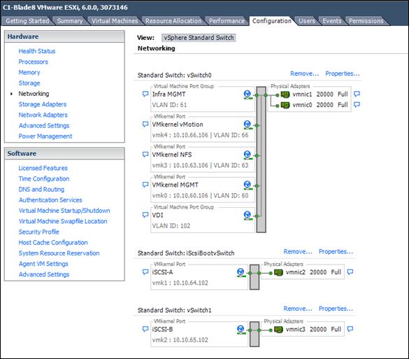
39. Repeat the above steps for all hosts or implement VMware Host Profiles once vCenter has been configured.
Mount Required Datastores
To mount the required datastores, complete the following steps on each ESXi host:
1. From the vSphere Client, select the host in the inventory.
2. To enable configurations, click the Configuration tab.
3. Click Storage in the Hardware pane.
4. From the Datastores area, click Add Storage to open the Add Storage wizard.
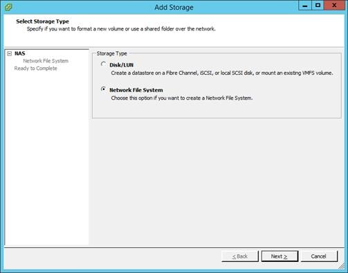
5. Select Network File System and click Next.
6. The wizard prompts for the location of the NFS export. Enter <<var_node02_nfs_lif_infra_datastore_1_ip>> as the IP address for nfs_lif_infra01.
7. Enter /infra01 as the path for the NFS export.
8. Confirm that the Mount NFS read only checkbox is not selected.
9. Enter NA-AFF-Infra01 as the datastore name.
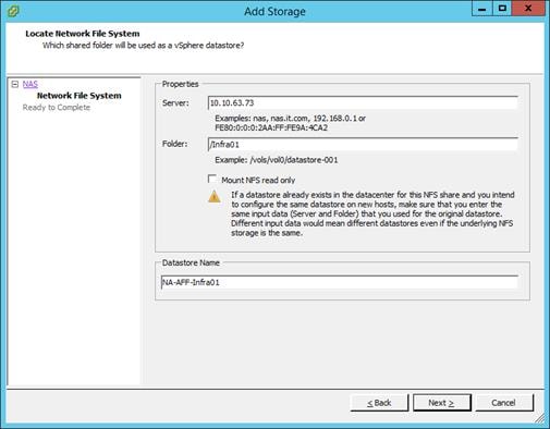
10. To continue with the NFS datastore creation, click Next.
11. To finalize the creation of the NFS datastore, click Finish.
12. From the Datastores area, click Add Storage to open the Add Storage wizard to mount the VM swap file datastore.
13. Select Network File System and click Next.
14. The wizard prompts for the location of the NFS export. Enter <<var_node01_nfs_lif_vmswp_ip>> as the IP address for nfs_lif_vmswp.
15. Enter / VMSWP as the path for the NFS export.
16. Confirm that the Mount NFS read only checkbox is not selected.
17. Enter NA-AFF-VMSWP as the datastore name.
18. To continue with the NFS datastore creation, click Next.
19. To finalize the creation of the NFS datastore, click Finish.
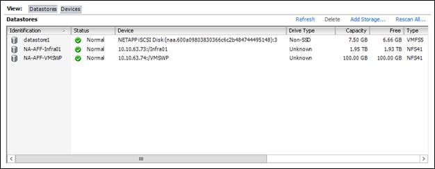
20. Repeat the above steps to mount the other NFS datastores to the RDS and VDI clusters’ host servers.
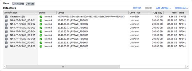
Configure NTP on ESXi Hosts
To configure Network Time Protocol (NTP) on the ESXi hosts, complete the following steps on each host:
1. From each vSphere Client, select the host in the inventory.
2. Click the Configuration tab to enable configurations.
3. Click Time Configuration in the Software pane.
4. Click Properties at the upper right side of the window.
5. At the bottom of the Time Configuration dialog box, click Options.
6. In the NTP Daemon Options dialog box, complete the following steps:
a. Click General in the left pane and select Start and stop with host.
b. Click NTP Settings in the left pane and click Add.
7. In the Add NTP Server dialog box, enter <<var_global_ntp_server_ip>> as the IP address of the NTP server and click OK.
8. In the NTP Daemon Options dialog box, select the Restart NTP Service to Apply Changes checkbox and click OK.
9. In the Time Configuration dialog box, complete the following steps:
a. Select the NTP Client Enabled checkbox and click OK.
b. Verify that the clock is now set to approximately the correct time.
![]() The NTP server time may vary slightly from the host time.
The NTP server time may vary slightly from the host time.
Move VM Swap File Location
To move the VM swap file location, complete the following steps on each ESXi host:
1. From the vSphere Client, select the host in the inventory.
2. To enable configurations, click the Configuration tab.
3. Click Virtual Machine Swapfile Location in the Software pane.
4. Click Edit at the upper-right side of the window.
5. Select “Store the swapfile in a swapfile datastore selected below.”
6. Select the <NA-AFF-VMSWP> datastore in which to house the swap files.
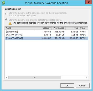
7. Click OK to finalize moving the swap file location.
Install and Configure vCenter 6.0
The procedures in the following subsections provide detailed instructions for installing the VMware vCenter 6.0 Server Appliance in an environment. After the procedures are completed, a VMware vCenter Server will be configured.
FlexPod VMware vCenter Appliance
The procedures in the following subsections provide detailed instructions for installing VMware vCenter 6.0 Update 1 in a FlexPod environment. After the procedures are completed, a VMware vCenter Server will be configured.
Install the Client Integration Plug-in
To install the client integration plug-in, complete the following steps:
1. Download the .iso installer for the vCenter Server Appliance and Client Integration Plug-in.
2. Mount the ISO image to the Windows virtual machine or physical server on which you want to install the Client Integration Plug-In to deploy the vCenter Server Appliance.
3. In the software installer directory, navigate to the vcsa directory and double-click VMware-ClientIntegrationPlugin-6.0.0.exe. The Client Integration Plug-in installation wizard appears.
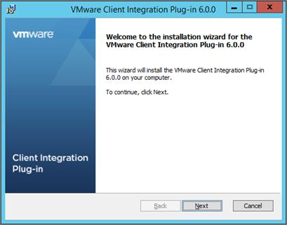
4. On the Welcome page, click Next.
5. Read and accept the terms in the End-User License Agreement and click Next.
6. Click Next.
7. Click Install.
Build and Setup VMware vCenter VM
To build the VMware vCenter virtual machine, complete the following steps:
1. In the software installer directory, double-click vcsa-setup.html.
2. Allow the plug-in to run on the browser when prompted.
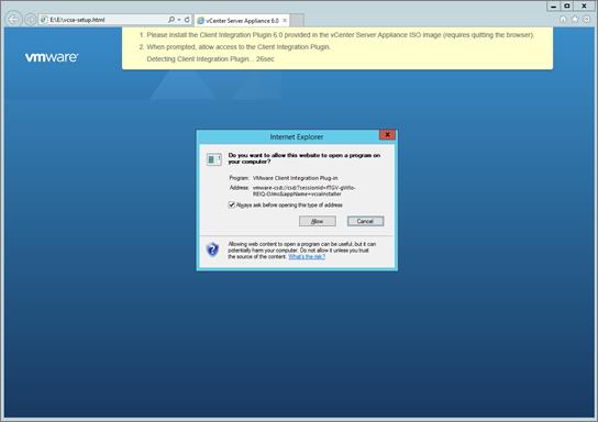
3. On the Home page, click Install to start the vCenter Server Appliance deployment wizard.
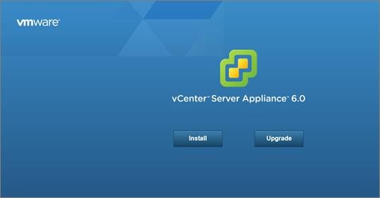
4. Read and accept the license agreement, and click Next.
5. In the “Connect to target server” page, enter the ESXi host name, User name and Password.
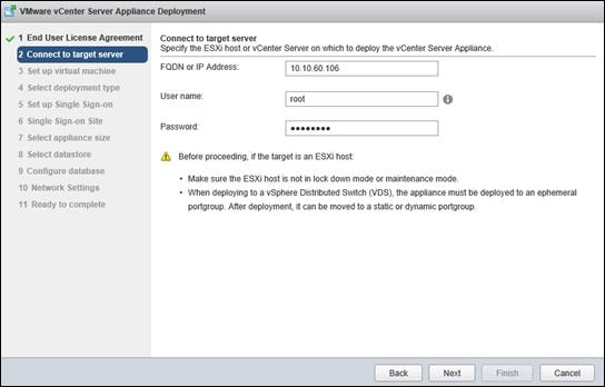
6. Click Yes to accept the certificate.
7. Enter the Appliance name and password details in the “Set up virtual machine” page.
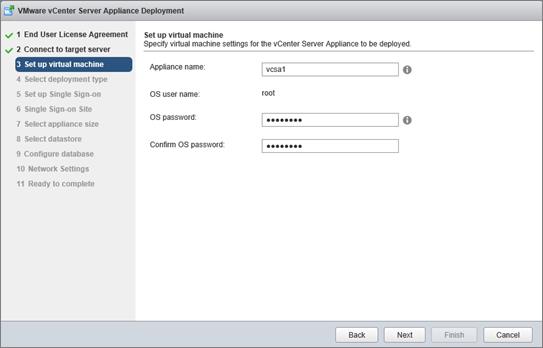
8. In the “Select deployment type” page, choose “Install vCenter Server with an embedded Platform Services Controller”.
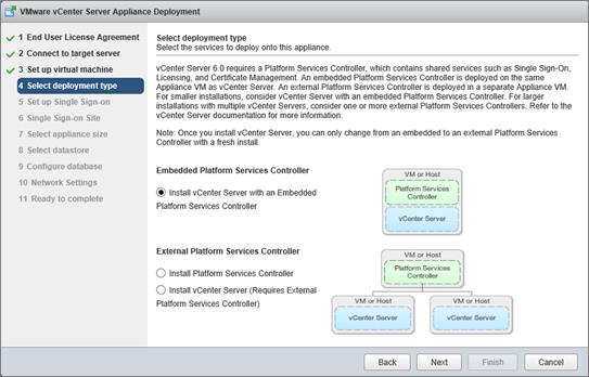
9. Click Next.
10. In the “Set up Single Sign-On” page, select “Create a new SSO domain.”
11. Enter the SSO password, Domain name and Site name.
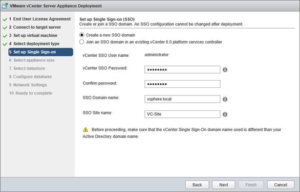
12. Click Next.
13. Select the appliance size. For example, “Tiny (up to 10 hosts, 100 VMs).”
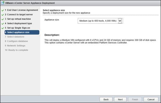
14. Click Next.
15. In the “Select datastore” page, choose infra_datastore_1.
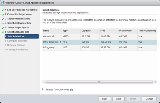
16. Click Next.
17. Select embedded database in the “Configure database” page. Click Next.
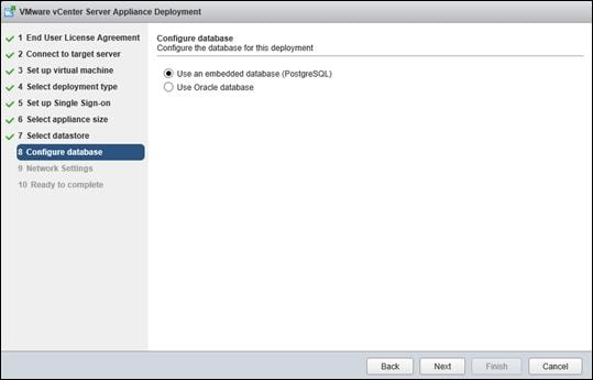
18. In the “Network Settings” page, configure the below settings:
a. Choose a Network: MGMT-Network
b. IP address family: IPV4
c. Network type: static
d. Network address: <<var_vcenter_ip>>
e. System name: <<var_vcenter_fqdn>>
f. Subnet mask: <<var_vcenter_subnet_mask>>
g. Network gateway: <<var_vcenter_gateway>>
h. Network DNS Servers: <<var_dns_server>>
i. Configure time sync: Use NTP servers
j. (Optional). Enable SSH
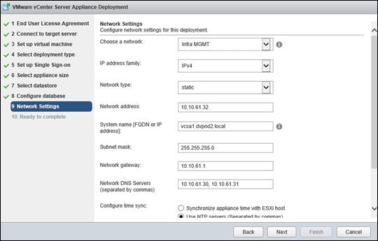
19. Review the configuration and click Finish.
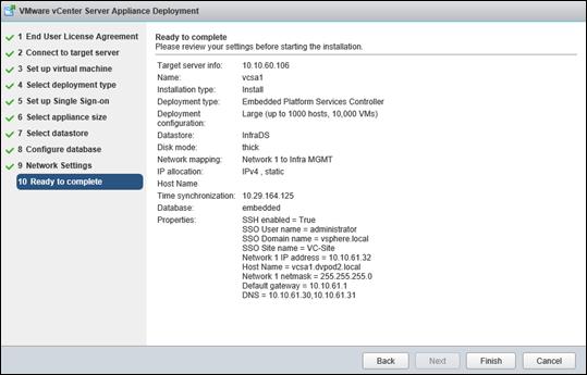
20. The vCenter appliance installation will take few minutes to complete.
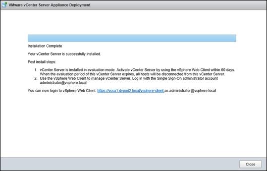
Setup VMware vCenter Server
To set up vCenter Server Appliance configuration, complete the following steps:
1. Using a web browser, navigate to https://<<var_vcenter_ip>.
2. Click Log in to vSphere Web Client.
3. Click OK if “Launch Application” window appears.
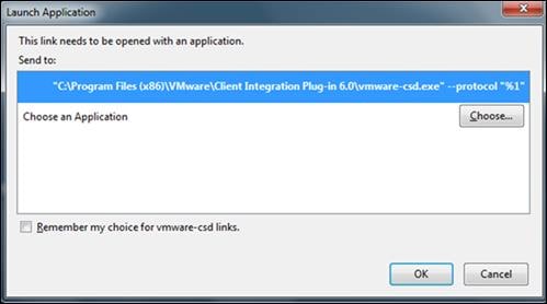
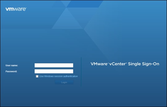
4. Log in using Single Sign-On username and password created during the vCenter installation.
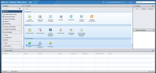
5. Navigate to vCenter Inventory Lists on the left pane.
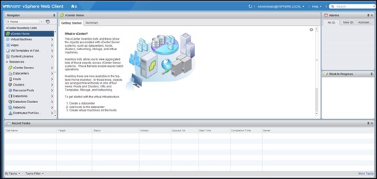
6. Under Resources, click Datacenters in the left plane.
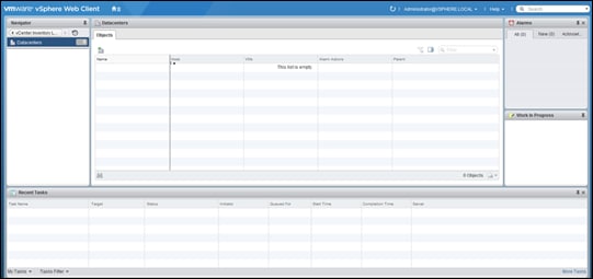
7. To create a Data center, click the leftmost icon in the center pane that has a green plus symbol above it.
8. Type FlexPod_DC in the Datacenter name field.
9. Select the vCenter Name/IP option.
10. Click OK.
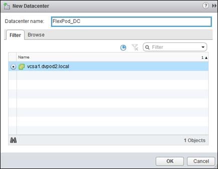
11. Right-click the data center FlexPod_DC in the list in the center pane. Click New Cluster.
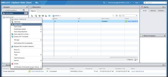
12. Name the cluster Infrastructure.
13. Check the box beside DRS. Leave the default values.
14. Check the box beside vSphere HA. Leave the default values.
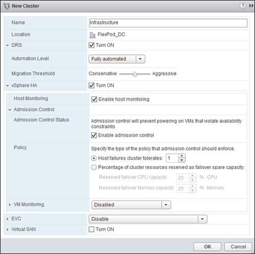
![]() If mixing Cisco UCS B or C-Series M3 and M4 servers within a vCenter cluster, it is necessary to enable VMware Enhanced vMotion Compatibility (EVC) mode. For more information about setting up EVC mode, refer to Enhanced vMotion Compatibility (EVC) Processor Support.
If mixing Cisco UCS B or C-Series M3 and M4 servers within a vCenter cluster, it is necessary to enable VMware Enhanced vMotion Compatibility (EVC) mode. For more information about setting up EVC mode, refer to Enhanced vMotion Compatibility (EVC) Processor Support.
15. Click OK to create the new cluster.
16. Repeat steps 11 thru 15 to create the VDI and RDS clusters.
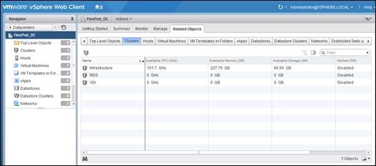
17. On the left pane, double click the “FlexPod_DC”.
18. Click Clusters.
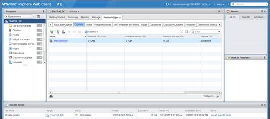
19. Under the Clusters pane, right click the “Infrastructure” and select Settings.
20. Select Configuration > General in the list on the left and select Edit to the right of General.
21. Select Datastore specified by host and click OK.
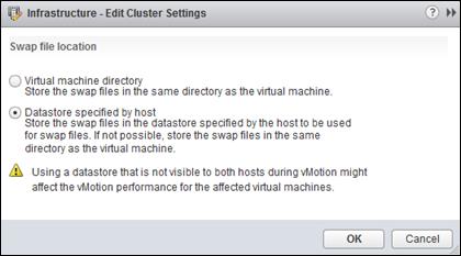
22. Under the Clusters pane, right click the “Infrastructure” and click Add Host.
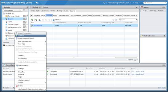
23. In the Host field, enter either the IP address or the host name of one of the VMware ESXi hosts. Click Next.
24. Type root as the user name and the root password. Click Next to continue.
25. Click Yes to accept the certificate.
26. Review the host details and click Next to continue.
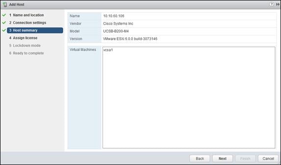
27. Assign a license and click Next to continue.
28. Click Next to continue.
29. Click Next to continue.
30. Review the configuration parameters. Then click Finish to add the host.
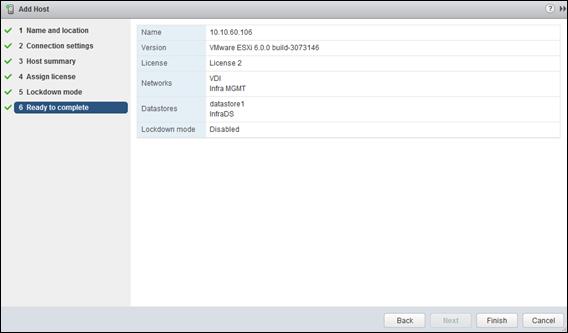
31. Repeat the steps 18 to 27 to add the remaining VMware ESXi hosts to the cluster.
![]() 28 VMware ESXi hosts will be added to the cluster.
28 VMware ESXi hosts will be added to the cluster.
ESXi Dump Collector Setup for iSCSI-Booted Hosts
ESXi hosts booted with iSCSI using the VMware iSCSI software initiator need to be configured to do core dumps to the ESXi Dump Collector that is part of vCenter. The Dump Collector is not enabled by default on the vCenter Appliance. To setup the ESXi Dump Collector, complete the following steps:
1. In the vSphere web client, select Home.
2. In the center pane, click System Configuration.
3. In the left hand pane, click VMware vSphere ESXi Dump Collector.
4. In the Actions menu, choose Start.
5. In the Actions menu, click Edit Startup Type.
6. Select Automatic.
7. Click OK.
8. On the Management Workstation, open the VMware vSphere CLI command prompt.
9. Set each iSCSI-booted ESXi Host to coredump to the ESXi Dump Collector by running the following commands:
esxcli –s <<var_vm_host_ip>> -u root –p <<var_password>> --thumbprint <host_thumbprint> system coredump network set –-interface-name vmk0 –-server-ipv4 <<var_vcenter_server_ip> --server-port 6500
![]() To get the host thumbprint, type the command without the –-thumbprint option, then copy and paste the thumbprint into the command.
To get the host thumbprint, type the command without the –-thumbprint option, then copy and paste the thumbprint into the command.
esxcli –s <<var_vm_host_ip>> -u root –p <<var_password>> --thumbprint <host_thumbprint> system coredump network set –-enable true
esxcli –s <<var_vm_host_ip>> -u root –p <<var_password>> --thumbprint <host_thumbprint> system coredump network check
NetApp Storage Configuration for VMware vSphere 6.0 Infrastructure and Virtual Desktop Agent (VDA) Virtual Machines
This section describes the configuration of NetApp storage in a VMware ESXi environment using Virtual Desktop Agent (VDA) VMs.
Installing and configuring NetApp Virtual Storage Console (VSC)
To Install the NetApp VSC, refer to the Virtual Storage Console 6.2 for VMware vSphere Installation and Administration Guide.
NetApp’s Virtual Storage Console (VSC) was used to provision (create) the persistent virtual desktops. The benefits of utilizing VSC to provision persistent desktops are the following:
§ VSC removes any meta-data processing at the hypervisor layer.
§ All provisioning IO is offloaded to the storage array.
§ VSC deduplicates the VDI image blocks as the persistent desktops are created.
The following are the steps to provision VDI persistent desktops with NetApp’s Virtual Storage Console.
1. Start VMware vCenter Web Client and right-click the VDI desktop template you plan to use to provision the persistent desktops.
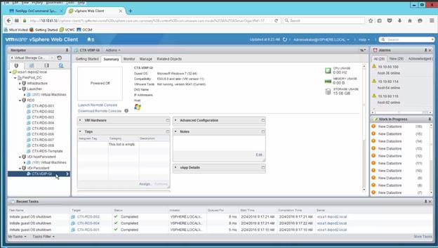
2. Right-click the VDI desktop template you plan to use to provision the persistent desktops, a menu will appear. Point your mouse to the NetApp VSC and then click on the “Create Rapid Clones” sub-menu item.
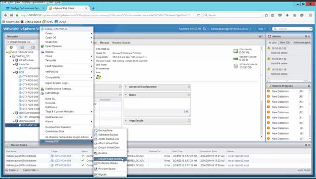
3. Select your clone destination (the location where the VDI persistent desktops will reside) and click Next to continue.
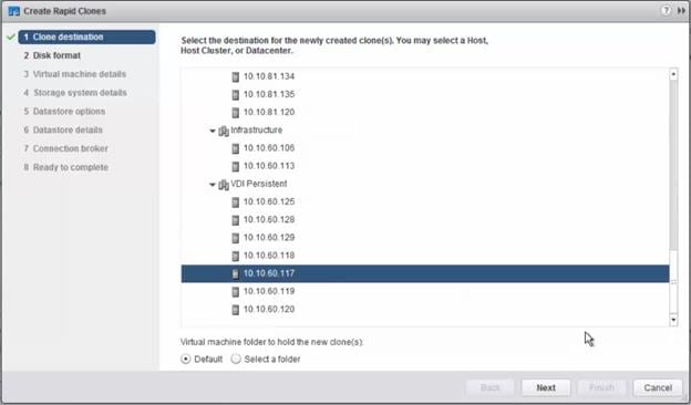
4. Select the VMware Disk format. NetApp recommends “Thick” format because the storage will eliminate the continuous zeros with Inline deduplication before it writes to the Solid State Drives. Click Next to continue.
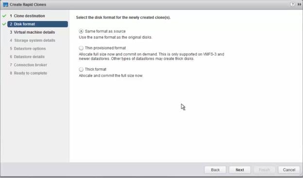
5. Enter the following for each VDI persistent desktop:
a. Number of virtual processors (vCPUs) that you will be using per persistent desktop. For this reference architecture, we used 2 vCPUs per VDI persistent desktop.
b. The memory to be allocated.
c. The number of clones (persistent desktops) to be provisioned.
d. Select “Citrix XenDesktop 5.0” for the VDI broker version. “Citrix XenDesktop 5.0” represents version 5.0 and greater (7.7, etc.).
e. Enter a VMware customization specification script to be run after the desktops are provisioned. This is a good method to have the desktops join the MS Active Domain.
f. Enter the naming structure you want to use for the VDI persistent desktops, the starting clone number and the increment number.
g. Verify the naming and number structure in the “Clone Name Preview” window.
6. Click Next to continue.
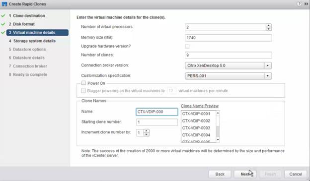
7. Choose the NetApp storage system cluster and the Storage Virtual Machine (SVM) and click Next to continue.
![]() You may receive a warning message for protocols not available on this SVM. This is an informational message and this message can be ignored if those protocols are not required for the persistent desktops.
You may receive a warning message for protocols not available on this SVM. This is an informational message and this message can be ignored if those protocols are not required for the persistent desktops.
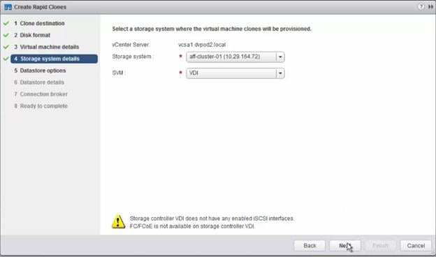
8. VSC has the capability to provision all the persistent desktops in one datastore / storage volume (Basic) or multiple volumes (Advanced). For this reference architecture, we used Basic. Select the Datastore option and click Next to continue.
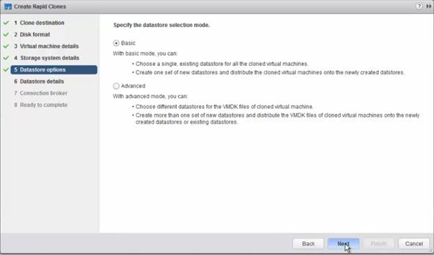
9. Select the datastore location for the VDI persistent desktops and click Next to continue.
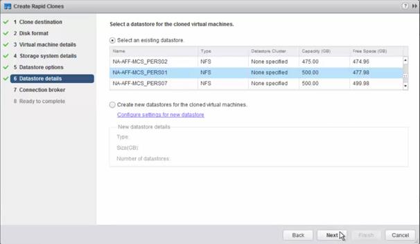
10. Select the Citrix Connect broker to be used and click Next to continue.
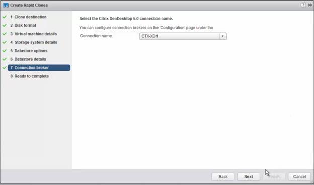
11. Verify the settings selected in the summary screen and if correct, click Next to continue.
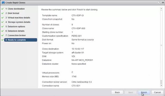
12. The Success Message will appear if the provisioning (cloning) process started correctly, click OK to continue.

13. Go to the vCenter WebClient and you can monitor the progress of the cloning (provisioning).
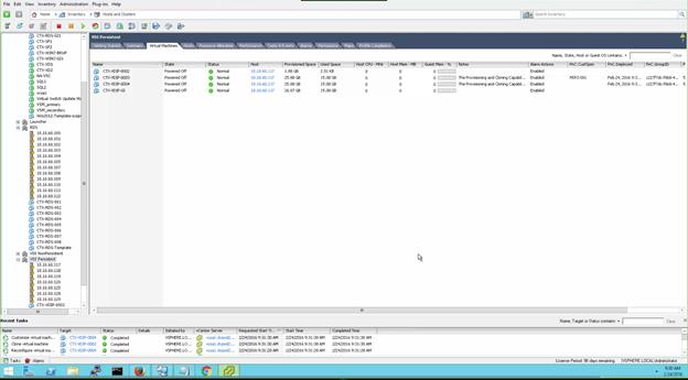
14. After all the VDI persistent desktops are provisioned (cloned), you will need to import the VDI desktops into Citrix Studio broker. In order to import the VDI persistent desktops into Citrix Studio, you will need to create a comma delimited file first. The layout of the comma delimited file is the following:
a. VDI persistent desktop path location (Virtual MachinePath)
b. Microsoft Active Domain Computer Account name for the persistent desktop
c. Number (unique number for each desktop)
Figure 30 depicts an example of the comma delimited file that will be used to import the persistent desktops into Citrix Studio.
Figure 30 Comma Delimited File Citrix Studio Import Example
|
|
| XDHyp:\Connections\vSphere Connection\FlexPod_DC.datacenter\VDI Persistent.cluster\CTX-VDIP-0001.vm,DVPOD2\CTX-VDIP-0001$,1 |
| XDHyp:\Connections\vSphere Connection\FlexPod_DC.datacenter\VDI Persistent.cluster\CTX-VDIP-0002.vm,DVPOD2\CTX-VDIP-0002$,2 |
| XDHyp:\Connections\vSphere Connection\FlexPod_DC.datacenter\VDI Persistent.cluster\CTX-VDIP-0003.vm,DVPOD2\CTX-VDIP-0003$,3 |
| XDHyp:\Connections\vSphere Connection\FlexPod_DC.datacenter\VDI Persistent.cluster\CTX-VDIP-0004.vm,DVPOD2\CTX-VDIP-0004$,4 |
| XDHyp:\Connections\vSphere Connection\FlexPod_DC.datacenter\VDI Persistent.cluster\CTX-VDIP-0005.vm,DVPOD2\CTX-VDIP-0005$,5 |
| XDHyp:\Connections\vSphere Connection\FlexPod_DC.datacenter\VDI Persistent.cluster\CTX-VDIP-0006.vm,DVPOD2\CTX-VDIP-0006$,6 |
| XDHyp:\Connections\vSphere Connection\FlexPod_DC.datacenter\VDI Persistent.cluster\CTX-VDIP-0007.vm,DVPOD2\CTX-VDIP-0007$,7 |
| XDHyp:\Connections\vSphere Connection\FlexPod_DC.datacenter\VDI Persistent.cluster\CTX-VDIP-0008.vm,DVPOD2\CTX-VDIP-0008$,8 |
| XDHyp:\Connections\vSphere Connection\FlexPod_DC.datacenter\VDI Persistent.cluster\CTX-VDIP-0009.vm,DVPOD2\CTX-VDIP-0009$,9 |
| XDHyp:\Connections\vSphere Connection\FlexPod_DC.datacenter\VDI Persistent.cluster\CTX-VDIP-0010.vm,DVPOD2\CTX-VDIP-0010$,10 |
| XDHyp:\Connections\vSphere Connection\FlexPod_DC.datacenter\VDI Persistent.cluster\CTX-VDIP-0011.vm,DVPOD2\CTX-VDIP-0011$,11 |
| XDHyp:\Connections\vSphere Connection\FlexPod_DC.datacenter\VDI Persistent.cluster\CTX-VDIP-0012.vm,DVPOD2\CTX-VDIP-0012$,12 |
| XDHyp:\Connections\vSphere Connection\FlexPod_DC.datacenter\VDI Persistent.cluster\CTX-VDIP-0013.vm,DVPOD2\CTX-VDIP-0013$,13 |
15. Launch Citrix Studio and go to the Machine Catalogue screen. Right click on the Machine Catalogue group that you use to import the persistent desktops and click on Add Machines menu item.
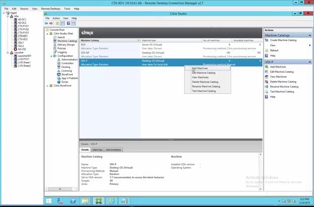
16. Click Import list.
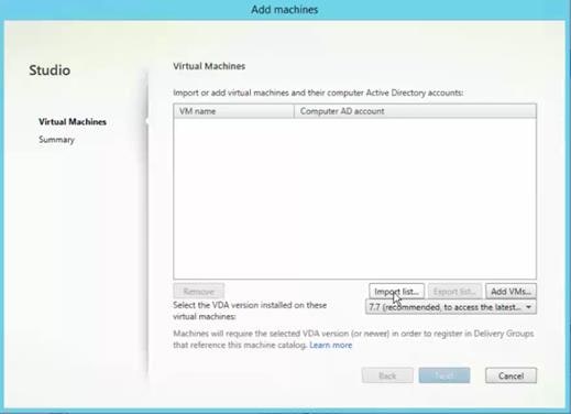
17. Browse and select the Import CVS file that you created and click Open.
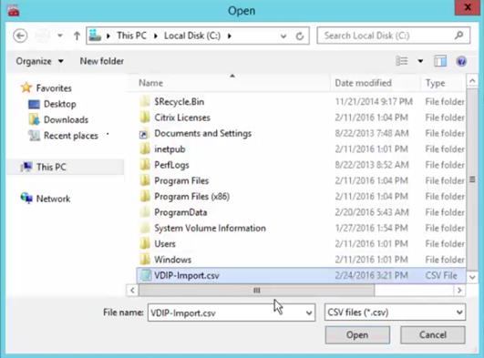
18. A preview screen will appear with the list of VDI persistent desktops that will be imported. Review the list and if correct, click Next.
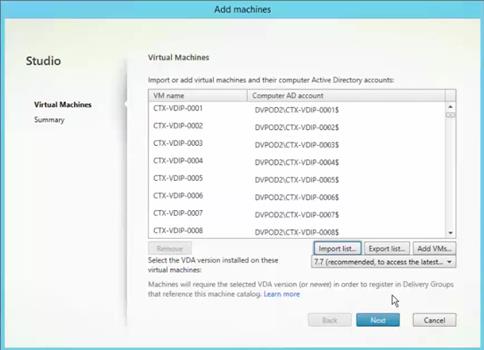
19. A progress bar will be display while the desktops are being imported into the Machine Catalogue. This process can take a long time of there are a large number of desktops to be imported. When completed, the Citrix Studio Machine Catalogue screen will appear.
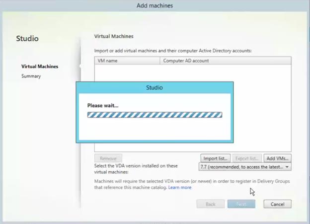
20. The process is complete and you have just provisioned the VDI persistent desktops with NetApp’s VSC tool and then you imported them into Citrix Studio Machine Catalogue (Citrix broker).
VLANs in Clustered Data ONTAP
To configure a VLAN in clustered Data ONTAP, complete the following steps.
1. Create NFS VLAN ports and add them to the data broadcast domain.
network port vlan create –node <<var_node01>> -vlan-name e0c-<<var_nfs_vlan_id>>
network port vlan create –node <<var_node01>> -vlan-name e0d-<<var_nfs_vlan_id>>
network port vlan create –node <<var_node02>> -vlan-name e0c-<<var_nfs_vlan_id>>
network port vlan create –node <<var_node02>> -vlan-name e0d-<<var_nfs_vlan_id>>
broadcast-domain add-ports -broadcast-domain Data -ports <<var_node01>>:e0c-<<var_nfs_vlan_id>>, <<var_node01>>:e0d-<<var_nfs_vlan_id>>,<<var_node02>>:e0c-<<var_nfs_vlan_id>>, <<var_node02>>:e0d-<<var_nfs_vlan_id>>
2. Create iSCSI VLAN ports and add them to the data broadcast domain.
network port vlan create –node <<var_node01>> -vlan-name e0c-<<var_iscsi_vlan_A_id>>
network port vlan create –node <<var_node01>> -vlan-name e0d-<<var_iscsi_vlan_B_id>>
network port vlan create –node <<var_node02>> -vlan-name e0c-<<var_iscsi_vlan_A_id>>
network port vlan create –node <<var_node02>> -vlan-name e0d-<<var_iscsi_vlan_B_id>>
broadcast-domain add-ports -broadcast-domain Data -ports <<var_node01>>:e0c-<<var_iscsi_vlan_A_id>>,<<var_node01>>:e0d-<<var_iscsi_vlan_B_id>>,<<var_node02>>:e0c-<<var_iscsi_vlan_A_id>>,<<var_node02>>:e0d-<<var_iscsi_vlan_B_id>>
Storage Virtual Machines
To create an infrastructure SVM, complete the following steps:
1. Run the SVM create command.
vserver create –vserver Infra-SVM –rootvolume rootvol –aggregate aggr1_node01 –rootvolume-security-style unix
2. Select the SVM data protocols to configure, leaving nfs, fcp, and iscsi.
vserver remove-protocols –vserver Infra-SVM -protocols cifs,ndmp
3. Add the two data aggregates to the Infra-SVM aggregate list for NetApp Virtual Storage Console (VSC).
vserver modify –vserver Infra-SVM –aggr-list aggr1_node01,aggr1_node02
4. Enable and run the NFS protocol in the Infra-SVM SVM.
nfs create -vserver Infra-SVM -udp disabled
5. Turn on the SVM vstorage parameter for the NetApp NFS VAAI Plug-in.
vserver nfs modify –vserver Infra-SVM –vstorage enabled
vserver nfs show
Create Load Sharing Mirror of SVM Root Volume in Clustered Data ONTAP
1. Create a volume to be the load sharing mirror of the infrastructure SVM root volume on each node.
volume create –vserver Infra-SVM –volume rootvol_m01 –aggregate aggr1_node01 –size 1GB –type DP
volume create –vserver Infra-SVM –volume rootvol_m02 –aggregate aggr1_node02 –size 1GB –type DP
2. Create a job schedule to update the root volume mirror relationships every 15 minutes.
job schedule interval create -name 15min -minutes 15
3. Create the mirroring relationships.
snapmirror create –source-path //Infra-SVM/rootvol –destination-path //Infra-SVM/rootvol_m01 –type LS -schedule 15min
snapmirror create –source-path //Infra-SVM/rootvol –destination-path //Infra-SVM/rootvol_m02 –type LS -schedule 15min
4. Initialize the mirroring relationship.
snapmirror initialize-ls-set –source-path //Infra-SVM/rootvol
snapmirror show
FCP Service in Clustered Data ONTAP
Create the FCP service on each SVM. This command also starts the FCP service and sets the FCP worldwide node name (WWNN) for the SVM.
fcp create -vserver Infra-SVM
fcp show
iSCSI Service in Clustered Data ONTAP
To create the iSCSI service, run the following commands. These commands also start the iSCSI service and set the iSCSI IQN for the SVM.
iscsi create -vserver Infra-SVM
iscsi show
HTTPS Access in Clustered Data ONTAP
To configure secure access to the storage controller, complete the following steps:
1. Increase the privilege level to access the certificate commands.
set -privilege diag
Do you want to continue? {y|n}: y
2. Generally, a self-signed certificate is already in place. Verify the certificate by running the following command:
security certificate show
3. For each SVM shown, the certificate common name should match the DNS FQDN of the SVM. Delete the four default certificates and replace them with either self-signed certificates or certificates from a Certificate Authority (CA). To delete the default certificates, run the following commands:
security certificate delete [TAB] …
Example: security certificate delete -vserver Infra-SVM -common-name Infra-SVM -ca Infra-SVM -type server -serial 552429A6
![]() Deleting expired certificates before creating new ones is a best practice. Run the security certificate delete command to delete expired certificates. In the following command, use TAB completion to select and delete each default certificate.
Deleting expired certificates before creating new ones is a best practice. Run the security certificate delete command to delete expired certificates. In the following command, use TAB completion to select and delete each default certificate.
4. To generate and install self-signed certificates, run the following commands as one-time commands. Generate a server certificate for Infra-SVM and the cluster SVM. Again, use TAB completion to aid in completing these commands.
security certificate create [TAB] …
Example: security certificate create -common-name infra-svm.ciscorobo.com -type server -size 2048 -country US -state "California" -locality "San Jose" -organization "Cisco" -unit "UCS" -email-addr "abc@cisco.com" -expire-days 365 -protocol SSL -hash-function SHA256 -vserver Infra-SVM
5. To obtain the parameter values for that are required in the following step, run the security certificate show command.
6. Enable each certificate that was just created using the –server-enabled true and –client-enabled false parameters. Again use TAB completion.
security ssl modify [TAB] …
Example: security ssl modify -vserver clus -server-enabled true -client-enabled false -ca clus.ciscorobo.com -serial 55243646 -common-name clus.ciscorobo.com
7. Configure and enable SSL and HTTPS access and disable HTTP access.
system services web modify -external true -sslv3-enabled true
Warning: Modifying the cluster configuration will cause pending web service requests to be
interrupted as the web servers are restarted.
Do you want to continue {y|n}: y
system services firewall policy delete -policy mgmt -service http –vserver <<var_clustername>>
![]() It is normal for some of these commands to return an error message stating that the entry does not exist.
It is normal for some of these commands to return an error message stating that the entry does not exist.
8. Change back to the normal admin privilege level and make SVM logs available from the web.
set –privilege admin
vserver services web modify –name spi|ontapi|compat –vserver * -enabled true
NFSv3 in Clustered Data ONTAP
§ VMware NFS Datastores on NetApp
With VMware vSphere, you can use enterprise-class NFS arrays to provide concurrent access to datastores for all of the nodes in an ESXi cluster. This access method is very similar to Virtual Machine File System (VMFS) access. The NetApp NFS offers high performance, low per-port storage costs, and advanced data management capabilities.
Figure 30 shows an example of this configuration. Note that the storage layout is similar to the layout of a VMFS datastore, but each virtual disk file has its own I/O queue managed directly by the NetApp AFF system.
Figure 31 vSphere Cluster Connected to an NFS Datastore
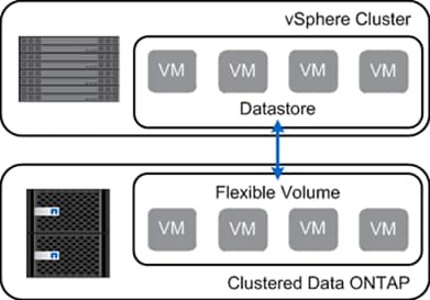
Deploying VMware with NetApp advanced NFS results in a high-performing, easy-to-manage implementation that provides VM-to-datastore ratios that cannot be obtained with block-based storage protocols. This architecture can result in a tenfold increase in datastore density with a correlated reduction in the number of datastores. With NFS, the virtual infrastructure receives operational savings because fewer storage pools are provisioned, managed, backed up, replicated, and so forth.
NFS integrates VMware virtualization technologies with WAFL, the NetApp advanced data management and storage virtualization engine. This integration provides transparent access to the following VM-level storage virtualization offerings:
§ Deduplication of production data
§ Immediate, zero-cost VM and datastore clones
§ Array-based thin provisioning
§ Automated policy-based datastore resizing
§ Direct access to array-based Snapshot copies
§ The ability to offload tasks to NetApp storage by using the NFS VMware VAAI plug-in
NetApp provides integrated tools, such as the VSC and the Site Replication Adapter for VMware Site Recovery Manager.
NFS Export Policies in NetApp Clustered Data ONTAP
Clustered Data ONTAP changes the architecture of exports by defining export policies scoped within an SVM. An export policy has a set of rules that determine which clients get which type of access. Each volume has exactly one export policy applied to it. All volumes that are used by the vSphere environment, or those that are used by each VMware cluster, can use the same export policy so that all hosts see the set of volumes in the same manner.
When a new host is added to the vSphere cluster, a rule for that host is added to the policy. The rule for the new host includes a client-match pattern (or simply an IP address) for the new host and a protocol. The rule also includes permissions and authentication methods for read and write, read only, a superuser, an anonymous user, and some other options that are of less significance for vSphere.
When a new volume is added and other volumes are already in use as datastores, the same export policy can be used for the new volume as was used for the previous volumes. For more information on clustered Data ONTAP export policies and junction paths, see TR-4068: VMware vSphere 5 on NetApp Clustered Data ONTAP.
To configure NFS on the SVM, run the following commands:
1. Create a new rule for each ESXi host in the default export policy.
For each ESXi host being created, assign a rule. Each host will have its own rule index. Your first ESXi host will have rule index 1, your second ESXi host will have rule index 2, and so on.
vserver export-policy rule create –vserver Infra-SVM -policyname default –ruleindex 1 –protocol nfs -clientmatch <<var_esxi_host1_nfs_ip>> -rorule sys –rwrule sys -superuser sys –allow-suid false
vserver export-policy rule create –vserver Infra-SVM -policyname default –ruleindex 2 –protocol nfs -clientmatch <<var_esxi_host2_nfs_ip>> -rorule sys –rwrule sys -superuser sys –allow-suid false
vserver export-policy rule show
2. Assign the FlexPod export policy to the infrastructure SVM root volume.
volume modify –vserver Infra-SVM –volume rootvol –policy default
FlexVol Volumes in Clustered Data ONTAP
This section describes the configuration of FlexVol volumes in clustered Data ONTAP.
NFS FlexVol Volumes
Volumes are data containers that enable you to partition and manage your data. Volumes are the highest-level logical storage objects. Unlike aggregates, which are composed of physical storage resources, volumes are completely logical objects. Understanding the types of volumes and their associated capabilities allows you to design your storage architecture for maximum storage efficiency and ease of administration.
A FlexVol volume is a data container associated with a storage virtual machine. It gets its storage from a single associated aggregate, which it might share with other FlexVol volumes or Infinite Volumes. It can be used to contain files in a NAS environment or LUNs in a SAN environment.
For practical purposes, NFS does not have a limit on the number of VMs per datastore. Also, the NFS protocol does not limit the addressable size of an NFS datastore, which means that it automatically supports the current clustered Data ONTAP volume size limit. With this in mind, VMs can be grouped according to business requirements, which can be organizational (department, tenant, or application) or service-level based, such as the type of storage, replication requirements, or schedule.
| Best Practices |
| § Create a minimum of two volumes per storage node. § Group similar data on each volume for better deduplication ratios. § Set auto-grow on the volumes. § Set Delete Oldest Snapshots when running low on space on a volume. § Utilize Thin Provisioning on Volumes when possible. § Setup reallocation jobs to run against each volume on all storage nodes (except root volumes).
|
Deduplication with FlexVol Volumes
NetApp can help you use less storage space. Citrix XenDesktop environments can benefit from the cost savings associated with NetApp deduplication (dedupe), as discussed in section 3.6. Each VM consumes storage as new writes occur. Scheduling and monitoring deduplication operations for the NetApp volumes hosting VMs are very important.
You should schedule dedupe operations to run during off-peak hours so that the experience of end users is not affected. You should also understand the number of simultaneous dedupe operations that can be performed on the storage controller. Planning for dedupe operations ultimately depends on your environment. The status and storage savings of dedupe operations can be monitored with NetApp OnCommand System Manager or the VSC deduplication Management tab. For details on NetApp deduplication, refer to NetApp TR-3505: NetApp Deduplication for AFF, Deployment and Implementation Guide.
Unlock the power of deduplication and optimize space utilization on user data, personal vDisks, infrastructure, and vDisk volumes.
Table 80 summarizes NetApp recommendations for deduplication in the XenDesktop environment.
Table 80 Table 1) Deduplication recommendations.
| Storage Type | Is Deduplication Recommended? | Reason |
| vDisk | Yes | OS data can be deduplicated. |
| Write cache | No | Log files and page files are temporary, transient data. Therefore, do not enable dedupe on these volumes. Doing so wastes storage resources. |
| Personal vDisk | Yes | Use dedupe on the same applications between the users. |
| User data and profile | Yes | Use dedupe on user data and profiles. |
The following information is required to create a FlexVol volume: the volume’s name, size, and the aggregate on which it exists. Create two VMware datastore volumes and a server boot volume. Also, update the SVM root volume load sharing mirrors to make the NFS mounts accessible.
volume create -vserver Infra-SVM -volume infra_datastore_1 -aggregate aggr1_node02 -size 500GB -state online -policy default -junction-path /infra_datastore_1 -space-guarantee none -percent-snapshot-space 0
volume create -vserver Infra-SVM -volume infra_swap -aggregate aggr1_node01 -size 100GB -state online -policy default -junction-path /infra_swap -space-guarantee none -percent-snapshot-space 0 -snapshot-policy none
volume create -vserver Infra-SVM -volume esxi_boot -aggregate aggr1_node01 -size 100GB -state online -policy default -space-guarantee none -percent-snapshot-space 0
snapmirror update-ls-set -source-path //Infra-SVM/rootvol
LUNs in Clustered Data ONTAP
To create two boot LUNs, run the following commands.
lun create -vserver Infra-SVM -volume esxi_boot -lun VM-Host-Infra-01 -size 15GB -ostype vmware -space-reserve disabled
lun create -vserver Infra-SVM -volume esxi_boot -lun VM-Host-Infra-02 -size 15GB -ostype vmware -space-reserve disabled
Deduplication in Clustered Data ONTAP
To enable deduplication on the appropriate volumes, run the following commands:
volume efficiency on –vserver Infra-SVM -volume infra_datastore_1
volume efficiency on –vserver Infra-SVM -volume esxi_boot
LIF Creation in Clustered Data ONTAP
NetApp OnCommand System Manager can be used to set up volumes and LIFs. Although LIFs can be created and managed through the command line, this document focuses on configuration using the NetApp OnCommand System Manager GUI.
![]() OnCommand System Manager 3.1 or later is required to set up LIFs.
OnCommand System Manager 3.1 or later is required to set up LIFs.
For good housekeeping purposes, NetApp recommends creating a new LIF whenever a new volume is created. A key feature in clustered Data ONTAP is the ability to move volumes in the same SVM from one node to another. When you move a volume, make sure that you move the associated LIF as well. This will help keep the virtual cabling neat and prevent the indirect I/O that occurs if the migrated volume does not have a LIF associated.
It is also a best practice to use the same port on each physical node for the same purpose. Due to the increased functionality of clustered Data ONTAP, more physical cables are necessary and can quickly become an administrative problem if care is not taken during labeling and placement. By using the same port on each cluster for the same purpose, you always know what each port does.
| Best Practices |
| § Each NFS datastore should have a data LIF for every node in the cluster. § When you create a new SVM, add one LIF per protocol per node. |
Fibre Channel Protocol LIFs in Clustered Data ONTAP
To create four FCoE LIFs (two on each node), run the following commands:
network interface create -vserver Infra-SVM -lif fcp_lif01a -role data -data-protocol fcp -home-node <<var_node01>> -home-port 0c –status-admin up –failover-policy disabled –auto-revert false
network interface create -vserver Infra-SVM -lif fcp_lif01b -role data -data-protocol fcp -home-node <<var_node01>> -home-port 0d –status-admin up –failover-policy disabled –auto-revert false
network interface create -vserver Infra-SVM -lif fcp_lif02a -role data -data-protocol fcp -home-node <<var_node02>> -home-port 0c –status-admin up –failover-policy disabled –auto-revert false
network interface create -vserver Infra-SVM -lif fcp_lif02b -role data -data-protocol fcp -home-node <<var_node02>> -home-port 0d –status-admin up –failover-policy disabled –auto-revert false
iSCSI LIFs in Clustered Data ONTAP
To create four iSCSI LIFs (two on each node), run the following commands:
network interface create -vserver Infra-SVM -lif iscsi_lif01a -role data -data-protocol iscsi -home-node <<var_node01>> -home-port e0c-<<var_iscsi_vlan_A_id>> -address <<var_node01_iscsi_lif01a_ip>> -netmask <<var_node01_iscsi_lif01a_mask>> –status-admin up –failover-policy disabled –firewall-policy data –auto-revert false
network interface create -vserver Infra-SVM -lif iscsi_lif01b -role data -data-protocol iscsi -home-node <<var_node01>> -home-port e0d-<<var_iscsi_vlan_B_id>> -address <<var_node01_iscsi_lif01b_ip>> -netmask <<var_node01_iscsi_lif01b_mask>> –status-admin up –failover-policy disabled –firewall-policy data –auto-revert false
network interface create -vserver Infra-SVM -lif iscsi_lif02a -role data -data-protocol iscsi -home-node <<var_node02>> -home-port e0c-<<var_iscsi_vlan_A_id>> -address <<var_node02_iscsi_lif01a_ip>> -netmask <<var_node02_iscsi_lif01a_mask>> –status-admin up –failover-policy disabled –firewall-policy data –auto-revert false
network interface create -vserver Infra-SVM -lif iscsi_lif02b -role data -data-protocol iscsi -home-node <<var_node02>> -home-port e0d-<<var_iscsi_vlan_B_id>> -address <<var_node02_iscsi_lif01b_ip>> -netmask <<var_node02_iscsi_lif01b_mask>> –status-admin up –failover-policy disabled –firewall-policy data –auto-revert false
network interface show
NAS Failover Groups in Clustered Data ONTAP
Create an NFS port failover group.
network interface failover-groups create –vserver Infra-SVM -failover-group fg-nfs-<<var_nfs_vlan_id>> -targets <<var_node01>>:e0c-<<var_nfs_vlan_id>>,<<var_node01>>:e0d-<<var_nfs_vlan_id>>,<<var_node02>>:e0c-<<var_nfs_vlan_id>>,<<var_node02>>:e0d-<<var_nfs_vlan_id>>
network interface failover-groups show
NFS LIF in Clustered Data ONTAP
Create an NFS LIF.
network interface create -vserver Infra-SVM -lif nfs_infra_swap -role data -data-protocol nfs -home-node <<var_node01>> -home-port e0d-<<var_nfs_vlan_id>> –address <<var_node01_nfs_lif_infra_swap_ip>> -netmask <<var_node01_nfs_lif_infra_swap_mask>> -status-admin up –failover-policy broadcast-domain-wide –firewall-policy data –auto-revert true –failover-group fg-nfs-<<var_nfs_vlan_id>>
network interface create -vserver Infra-SVM -lif nfs_infra_datastore_1 -role data -data-protocol nfs -home-node <<var_node02>> -home-port e0d-<<var_nfs_vlan_id>> –address <<var_node02_nfs_lif_infra_datastore_1_ip>> -netmask <<var_node02_nfs_lif_infra_datastore_1_mask>> -status-admin up –failover-policy broadcast-domain-wide –firewall-policy data –auto-revert true –failover-group fg-nfs-<<var_nfs_vlan_id>>
network interface show
NetApp recommends creating a new LIF for each datastore. Note that all NFS LIFs in this FlexPod setup are placed on ports that connect to the Fabric B UCS fabric interconnect, but these LIFs can fail over to ports connected to Fabric A.
Later in this document, server NFS VMkernel ports are also pinned to Fabric B in the Nexus 1000V. This pinning can also be done in a VMware vSwitch or vDS at the port group level. In a nonfailover situation, all NFS traffic is switched within the Fabric B fabric interconnect and does not have to cross fabrics.
LIF Migration
LIFs for NFS and CIFS can be migrated, but iSCSI LIFs cannot. If you have a Flash Cache, you might need the I/O Expansion Module (IOXM) to add another 10GbE card. If you use IOXM, you must connect the HA pair with a fiber cable.
| Best Practice |
| § Use 10GbE for cluster interconnection and data networks. NetApp recommends 1GbE for management networks. Make sure you have enough 10GbE cards and ports. |
Add Infrastructure SVM Administrator
To add the infrastructure SVM administrator and SVM administration logical interface in the out-of-band management network, complete the following steps:
1. Run the following commands:
network interface create –vserver Infra-SVM –lif vsmgmt –role data –data-protocol none –home-node <<var_node02>> -home-port e0a –address <<var_vserver_mgmt_ip>> -netmask <<var_vserver_mgmt_mask>> -status-admin up –failover-policy broadcast-domain-wide –firewall-policy mgmt –auto-revert true –failover-group fg-cluster-mgmt
![]() The SVM management IP should be in the same subnet as the storage cluster management IP.
The SVM management IP should be in the same subnet as the storage cluster management IP.
2. Create a default route to allow the SVM management interface to reach the outside world.
network route create –vserver Infra-SVM -destination 0.0.0.0/0 –gateway <<var_vserver_mgmt_gateway>>
Network route show
3. Set a password for the SVM vsadmin user and unlock the user.
security login password –username vsadmin –vserver Infra-SVM
Enter a new password: <<var_password>>
Enter it again: <<var_password>>
security login unlock –username vsadmin –vserver Infra-SVM
FlexPod Cisco Virtual Switch Update Manager and Nexus 1000V
This section details the installation of the Cisco Virtual Switch Update Manager (VSUM) and Cisco Nexus 1000V. This CVD installs three VMs that pertain to VSUM, VSM_primary, and VSM_secondary.
Installing Cisco Virtual Switch Update Manager
Verifying the Authenticity of the Cisco-Signed Image (Optional)
Before you install the Nexus1000v-vsum.1.5.x-pkg.zip image, you have the option to validate its authenticity. In the zip file, there is a signature.txt file that contains an SHA-512 signature and an executable script that can be used to verify the authenticity of the Nexus1000v-vsum.1.5.x-pkg.zip image.
|
| To set up the primary Cisco Nexus 1000V VSM on the Cisco Nexus 1110-X A, complete the following steps:
| ||
| 1. Copy the following files to a directory on the Linux machine: — Nexus1000v-vsum.1.5.x-pkg.zip image — signature.txt file — cisco_n1k_image_validation_v_1_5_x script | |||
|
| 2. Make sure that the script is executable. chmod 755 cisco_n1k_image_validation_v_1_5_x | ||
|
| 3. Run the script. ./cisco_n1k_image_validation_v_1_5_x -s signature.txt Nexus1000v-vsum.1.5.x-pkg.zip | ||
|
| 4. Check the output. If the validation is successful, the following message displays: Authenticity of Cisco-signed image Nexus1000v-vsum.1.5.x-pkg.zip has been successfully verified! | ||
Install Cisco Virtual Switch Update Manager
VMware vSphere Web Client
To install the Cisco Virtual Switch Upgrade Manager from OVA in the VMware virtual environment, complete the following steps:
1. Log into the VMware vSphere Web Client.
2. In the pane on the right, click VMs and Templates.
3. In the center pane, select Actions > Deploy OVF Template.
4. Select Browse and browse to and select the Nexus1000v-vsum.1.5.x.ova file.
5. Click Open.
6. Click Next.
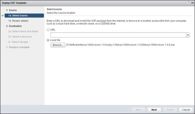
7. Review the details and click Next.
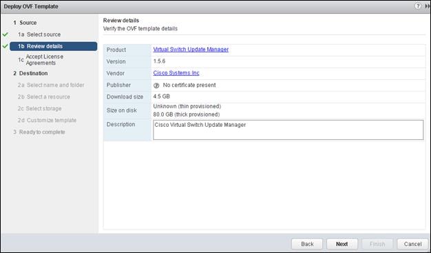
8. Click Accept to accept the License Agreement and click Next.
9. Name the Virtual Machine, select the FlexPod_DC datacenter and click Next.
10. Select the Infrastructure cluster and click Next.
11. Select NA-AFF-Infra01 and the Thin Provision virtual disk format and click Next.
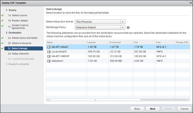
12. Select the MGMT Network and click Next.
13. Fill in the Networking Properties.
14. Expand the vCenter Properties and fil those in.
15. Click Next.
16. Review all settings and click Finish.
17. Wait for the Deploy OVF template task to complete.
18. Select the Home button in VMware vSphere Web Client and select Hosts and Clusters.
19. Expand the Infrastructure cluster and select the Virtual Switch Update Manager VM.
20. In the center pane, select Launch Remote Console. If a security warning pops up, click Allow.
21. If a security certificate warning pops up, click Connect Anyway.
22. Power on the Virtual Switch Update Manager VM.
23. When the VM has completely booted up, log out and log back into the VMware vSphere Web Client.
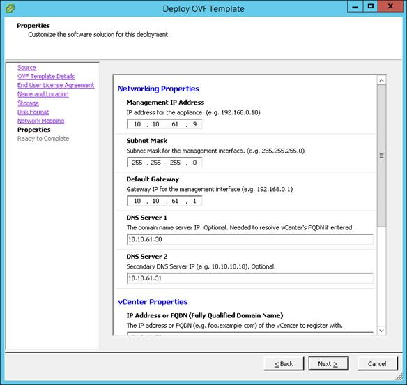
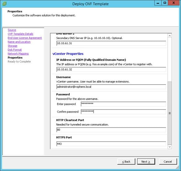
About the Cisco VSUM GUI
§ Cisco VSUM is a virtual appliance that is registered as a plug-in to the VMware vCenter Server.
§ The Cisco VSUM is the GUI that you use to install, migrate, monitor, and upgrade the VSMs in high availability (HA) or standalone mode and the VEMs on ESX/ESXi hosts.
Figure 32 VMware vSphere Web Client—Home Page
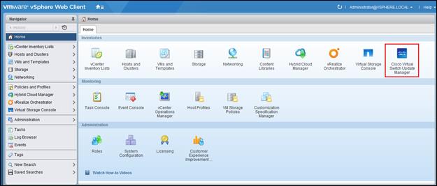
Figure 33 Cisco VSUM—Home Page
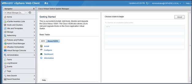
Install Cisco Nexus 1000V using Cisco VSUM
VMware vSphere Web Client
To install the Cisco Nexus 1000V switch by creating a new VSM, complete the following steps:
![]() Optionally, an existing VSM can be used that is provided by a Cisco Nexus Cloud Services Platform (CSP).
Optionally, an existing VSM can be used that is provided by a Cisco Nexus Cloud Services Platform (CSP).
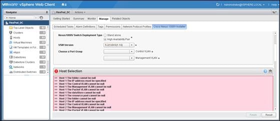
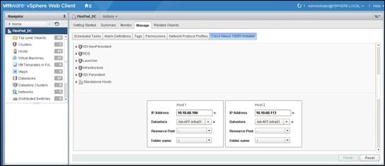
10. In the Virtual Supervisor Module (VSM) configuration area, enter the Switch Name, IP Address, Subnet Mask, and Gateway Address.
11. Do not select Default Port Profiles.
12. Enter the Password and Confirm Password for Admin.
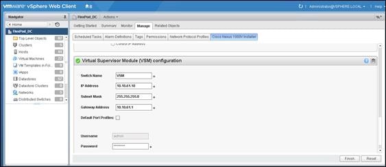
13. Click Finish to install the Cisco Nexus 1000V switch.
![]() The Cisco Nexus 1000V installation is confirmed when the primary task Create Nexus 1000v Switch has the status Completed. A typical installation of the switch takes about 4 minutes.
The Cisco Nexus 1000V installation is confirmed when the primary task Create Nexus 1000v Switch has the status Completed. A typical installation of the switch takes about 4 minutes.
Perform Base Configuration of the Primary VSM
SSH Connection to Primary VSM
To perform the base configuration of the primary VSM, complete the following steps:
1. Using an SSH client, log in to the primary Cisco Nexus 1000V VSM as admin.
2. Run the following configuration commands.
![]() Any VLAN that has a VMKernal port should be assigned as a system vlan on both the uplink and the vEthernet ports of the virtual switch.
Any VLAN that has a VMKernal port should be assigned as a system vlan on both the uplink and the vEthernet ports of the virtual switch.
config t
ntp server <<var_switch_a_ntp_ip>> use-vrf management
ntp server <<var_switch_b_ntp_ip>> use-vrf management
vlan <<var_native_vlan_id_1>>
name Native-VLAN
vlan <<var_ib-mgmt_vlan_id_60>>
name IB-MGMT-VLAN
vlan <<var_vm-traffic_vlan_id_61>>
name VM-INFRA-VLAN
vlan <<var_nfs_vlan_id_63>>
name NFS-VLAN
vlan <<var_iscsi_a_vlan_id_64>>
name iSCSI-A-VLAN
vlan <<var_iscsi_b_vlan_id_65>>
name iSCSI-B-VLAN
vlan <<var_vmotion_vlan_id_66>>
name vMotion-VLAN
![]() The Nexus 1000V is currently limited to 1024 Max ports per profile. This solution is comprised of 2,512 virtual desktop machines for the user workload and requires three dedicated port-profiles.
The Nexus 1000V is currently limited to 1024 Max ports per profile. This solution is comprised of 2,512 virtual desktop machines for the user workload and requires three dedicated port-profiles.
vlan <<var_vdi_vlan_id_102>>
name VDI-1-VLAN
vlan <<var_vdi_vlan_id_102>>
name VDI-2-VLAN
vlan <<var_vdi_vlan_id_102>>
name VDI-3-VLAN
vlan <<var_ob_mgmt_vlan_id_164>>
name OB-MGMT-VLAN
exit
port-profile type ethernet system-uplink
vmware port-group
switchport mode trunk
switchport trunk native vlan <<var_native_vlan_id_1>>
switchport trunk allowed vlan <<var_ib-mgmt_vlan_id_60>>, <<var_vm-infra_vlan_id_61>>, <<var_nfs_vlan_id_63>>, <<var_vmotion_vlan_id_66>>, <<var_vdi_vlan_id_102>>, <<var_ob-mgmt_vlan_id_164>>
channel-group auto mode on mac-pinning
no shutdown
system vlan <<var_ib-mgmt_vlan_id_60>>, <<var_vm-infra_vlan_id_61>>, <<var_nfs_vlan_id_63>>, <<var_vmotion_vlan_id_66>>
system mtu 9000
state enabled
port-profile type ethernet iscsi-a-uplink
vmware port-group
switchport mode trunk
switchport trunk native vlan <<var_iscsi_a_vlan_id_64>>
switchport trunk allowed vlan <<var_iscsi_a_vlan_id_64>>
no shutdown
system vlan <<var_iscsi_a_vlan_id_64>>
system mtu 9000
state enabled
port-profile type ethernet iscsi-b-uplink
vmware port-group
switchport mode trunk
switchport trunk native vlan <<var_iscsi_b_vlan_id_65>>
switchport trunk allowed vlan <<var_iscsi_b_vlan_id_65>>
no shutdown
system vlan <<var_iscsi_b_vlan_id_65>>
system mtu 9000
state enabled
port-profile type vethernet IB-MGMT-VLAN
vmware port-group
switchport mode access
switchport access vlan <<var_ib-mgmt_vlan_id_60>>
no shutdown
system vlan <<var_ib-mgmt_vlan_id_60>>
state enabled
port-profile type vethernet NFS-VLAN
vmware port-group
switchport mode access
switchport access vlan <<var_nfs_vlan_id_63>>
no shutdown
system vlan <<var_nfs_vlan_id_63>>
state enabled
port-profile type vethernet vMotion-VLAN
vmware port-group
switchport mode access
switchport access vlan <<var_vmotion_vlan_id_66>>
no shutdown
system vlan <<var_vmotion_vlan_id_66>>
state enabled
port-profile type vethernet VM-INFRA-VLAN
vmware port-group
switchport mode access
switchport access vlan <<var_vm-infra_vlan_id_61>>
no shutdown
system vlan <<var_vm-infra_vlan_id_61>>
state enabled
port-profile type vethernet n1kv-L3
capability l3control
vmware port-group
switchport mode access
switchport access vlan <<var_ib-mgmt_vlan_id_60>>
no shutdown
system vlan <<var_ib-mgmt_vlan_id_60>>
state enabled
port-profile type vethernet OB-MGMT-VLAN
vmware port-group
switchport mode access
switchport access vlan <<var_ob-mgmt_vlan_id_164>>
no shutdown
system vlan <<var_ob-mgmt_vlan_id_164>>
state enabled
port-profile type vethernet VDI-1-VLAN
vmware port-group
switchport mode access
switchport access vlan <<var_vdi_1_vlan_id_102>>
no shutdown
max-ports 1024
system vlan <<var_vdi_1_vlan_id_102>>
state enabled
port-profile type vethernet VDI-2-VLAN
vmware port-group
switchport mode access
switchport access vlan <<var_vdi_1_vlan_id_102>>
no shutdown
max-ports 1024
system vlan <<var_vdi_1_vlan_id_102>>
state enabled
port-profile type vethernet VDI-3-VLAN
vmware port-group
switchport mode access
switchport access vlan <<var_vdi_1_vlan_id_102>>
no shutdown
max-ports 1024
system vlan <<var_vdi_1_vlan_id_102>>
state enabled
port-profile type vethernet iSCSI-A-VLAN
vmware port-group
switchport mode access
switchport access vlan <<var_iscsi_a_vlan_id_64>>
no shutdown
system vlan <<var_iscsi_a_vlan_id_64>>
state enabled
port-profile type vethernet iSCSI-B-VLAN
vmware port-group
switchport mode access
switchport access vlan <<var_iscsi_b_vlan_id_65>>
no shutdown
system vlan <<var_iscsi_b_vlan_id_65>>
state enabled
exit
copy run start
Add VMware ESXi Hosts to Cisco Nexus 1000V
VMware vSphere Web Client
To and VMware ESXi hosts, complete the following steps:
1. Back in the VMware vSphere Web Client, from the Home tab, select Cisco Virtual Switch Update Manager.
2. Under Basic Tasks, select Nexus 1000V.
3. Select Configure.
4. Select the FlexPod_DC datacenter on the right.
5. Select the VSM on the lower right.
6. Click Manage.
7. In the center pane, select the Add Host tab.
8. Expand the Infrastructure ESXi Cluster and select one of the Infrastructure Management Hosts.
9. Click Suggest.
10. Scroll down to Physical NIC Migration and expand each ESXi host.
11. On both hosts, unselect vmnic0, and select vmnic1. For vmnic1, select the system-uplink Profile. Select vmnic2 and select the iscsi-a-uplink Profile. Select vmnic3 and select the iscsi-b-uplink Profile.
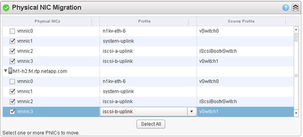
12. Scroll down to VM Kernel NIC Setup and expand both ESXi hosts.
13. All VMkernel ports should already have the appropriate checkboxes selected.
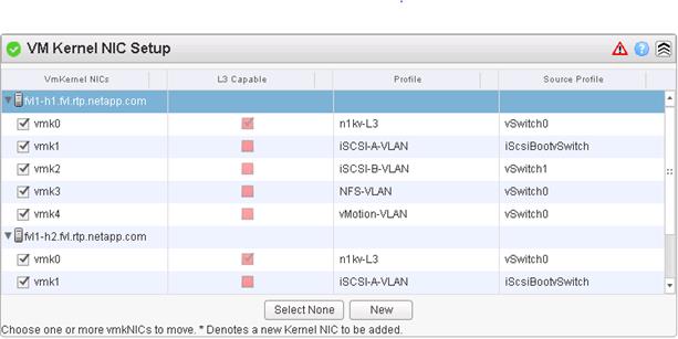
14. Scroll down to VM Migration and expand both ESXi hosts.
15. Select the IB-MGMT-VLAN profile for the VSUM and vCenter Virtual Machines.
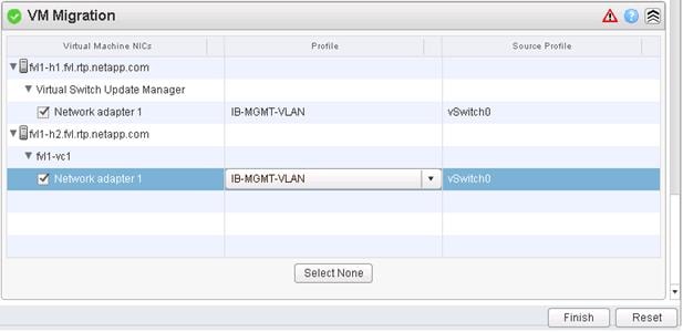
16. Click Finish.
![]() The progress of the virtual switch installation can be monitored from the c# interface.
The progress of the virtual switch installation can be monitored from the c# interface.
Migrate ESXi Host Redundant Network Ports to Cisco Nexus 1000V
To migrate the ESXi host redundant network ports, complete the following steps:
1. In the VMware vSphere Web Client window, select Home > Hosts and Clusters.
2. On the left expand the Datacenter and cluster, and select the first VMware ESXi host.
3. In the center pane, select the Manage tab, then select Networking.
4. Select vSwitch0. All of the port groups on vSwitch0 should be empty. Click the red X under Virtual switches to delete vSwitch0.
5. Click Yes to remove vSwitch0. It may be necessary to refresh the Web Client to see the deletion.
6. Delete iScsiBootvSwitch and vSwitch1.
7. The Nexus 1000V VSM should now be the only virtual switch. Select it and select the third icon above it under Virtual switches (Manage the physical network adapters connected to the selected switch).
8. Click the green plus sign to add an adapter.
9. For UpLink03, select the system-uplink port group and make sure vmnic0 is the Network adapter. Click OK.
10. Click OK to complete adding the Uplink. It may be necessary to refresh the Web Client to see the addition.
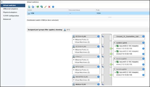
11. Repeat this procedure for the other ESXi host.
12. From the SSH client that is connected to the Cisco Nexus 1000V, run show interface status to verify that all interfaces and port channels have been correctly configured.
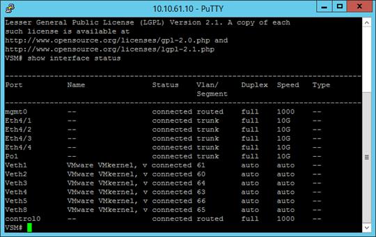
13. Run show module and verify that the one ESXi host is present as a module.
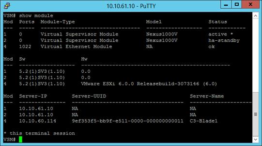
14. Repeat the above steps to migrate the remaining ESXi hosts to the Nexus 1000V.
15. Run: copy run start.
Cisco Nexus 1000V vTracker
The vTracker feature on the Cisco Nexus 1000V switch provides information about the virtual network environment. Once you enable vTracker, it becomes aware of all the modules and interfaces that are connected with the switch. vTracker provides various views that are based on the data sourced from the vCenter, the Cisco Discovery Protocol (CDP), and other related systems connected with the virtual switch. You can use vTracker to troubleshoot, monitor, and maintain the systems. Using vTracker show commands, you can access consolidated network information across the following views:
§ Upstream View—Provides information on all the virtual ports connected to an upstream physical switch. The view is from top of the network to the bottom.
§ VM View—Supports two sets of data:
§ VM vNIC View—Provides information about the virtual machines (VMs) that are managed by the Cisco Nexus 1000V switch. The vNIC view is from the bottom to the top of the network.
§ VM Info View—VM Info View—Provides information about all the VMs that run on each server module.
§ Module pNIC View—Provides information about the physical network interface cards (pNIC) that are connected to each Virtual Ethernet Module (VEM).
§ VLAN View—Provides information about all the VMs that are connected to specific VLANs.
§ vMotion View—Provides information about all the ongoing and previous VM migration events.
SSH Connection to Primary VSM to Enable vTracker
To connect SSH to the primary VSM, complete the following steps:
1. From an ssh interface connected to the Cisco Nexus 1000V VSM, enter the following:
config t
feature vtracker
copy run start
show vtracker upstream-view
show vtracker vm-view vnic
show vtracker vm-view info
show vtracker module-view pnic
show vtracker vlan-view
copy run start
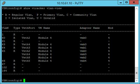
Building the Virtual Machines and Environment
Software Infrastructure Configuration
This section details how to configure the software infrastructure components that comprise this solution.
Install and configure the infrastructure virtual machines by following the process provided in Table 81.
Table 81 Test Infrastructure Virtual Machine Configuration
| Configuration | Citrix XenDesktop Controllers Virtual Machines | Citrix Provisioning Servers Virtual Machines |
| Operating system | Microsoft Windows Server 2012 R2 | Microsoft Windows Server 2012 R2 |
| Virtual CPU amount | 4 | 4 |
| Memory amount | 8 GB | 8 GB |
| Network | VMXNET3 VM-INFRA-vLAN (VSM) | VMXNET3 VM-INFRA-vLAN (VSM) |
| Disk-1 (OS) size and location | 40 GB Infra-DS volume | 40 GB Infra-DS volume |
| Disk-2 size and location | – | 500 GB PVS-vDisk volume using CIFS |
| Configuration | Microsoft Active Directory DCs Virtual Machines | vCenter Server Appliance Virtual Machine |
| Operating system | Microsoft Windows Server 2012 R2 | VCSA – SUSE Linux |
| Virtual CPU amount | 4 | 8 |
| Memory amount | 4 GB | 24 GB |
| Network | VMXNET3 VM-INFRA-vLAN (VSM) | VMXNET3 VM-INFRA-vLAN (VSM) |
| Disk size and location | 40 GB Infra-DS volume | 460 GB (across 11 VMDKs) Infra-DS volume |
| Configuration | Microsoft SQL Server Virtual Machine | NetApp VSC Virtual Machine |
| Operating system | Microsoft Windows Server 2012 R2 Microsoft SQL Server 2012 SP1 | Microsoft Windows Server 2012 R2 |
| Virtual CPU amount | 4 | 4 |
| Memory amount | 4 GB | 8 GB |
| Network | VMXNET3 VM-INFRA-vLAN (VSM) | VMXNET3 VM-INFRA-vLAN (VSM) |
| Disk-1 (OS) size and location | 40 GB Infra-DS volume | 40 GB Infra-DS volume |
| Disk-2 size and location | 100 GB Infra-DS volume SQL Logs | - |
| Disk-3 size and location | 150 GB Infra-DS volume SQL Databases | - |
Preparing the Master Targets
This section provides guidance around creating the golden (or master) images for the environment. VMs for the master targets must first be installed with the software components needed to build the golden images. For this CVD, the images contain the basics needed to run the Login VSI workload.
To prepare the master VMs for the Hosted Virtual Desktops (HVDs) and Hosted Shared Desktops (HSDs), there are three major steps: installing the PVS Target Device x64 software, installing the Virtual Delivery Agents (VDAs), and installing application software.
The master target HVD(VDI) and HSD(RDS) VMs were configured as follows in Table 82:
Table 82 VDI and RDS Configurations
| Configuration | VDI Virtual Machines | RDS Virtual Machines |
| Operating system | Microsoft Windows 7 SP1 32-bit | Microsoft Windows Server 2012 |
| Virtual CPU amount | 2 | 6 |
| Memory amount | 1.7 GB reserve for all guest memory | 24 GB reserve for all guest memory |
| Network | VMXNET3 VDI vLAN (VSM) | VMXNET3 VDI vLAN (VSM) |
| Citrix PVS vDisk size and location | 24 GB (dynamic) PVS-vDisk volume | 40 GB (dynamic) PVS-vDisk volume |
| Citrix PVS write cache Disk size | 6 GB | 30 GB |
| Citrix PVS write cache RAM cache size | 64 MB | 1024 MB |
| Additional software used for testing | Microsoft Office 2010 Login VSI 4.1.4 (Knowledge Worker Workload) | Microsoft Office 2010 Login VSI 4.1.4 (Knowledge Worker Workload) |
Installing and Configuring XenDesktop and XenApp
This section details the installation of the core components of the XenDesktop/XenApp 7.7 system. This CVD installs two XenDesktop Delivery Controllers to support both hosted shared desktops (RDS), non-persistent virtual desktops (VDI), and persistent virtual desktops (VDI).
Prerequisites
Citrix recommends that you use Secure HTTP (HTTPS) and a digital certificate to protect vSphere communications. Citrix recommends that you use a digital certificate issued by a certificate authority (CA) according to your organization's security policy. Otherwise, if security policy allows, use the VMware-installed self-signed certificate.
To install vCenter Server self-signed Certificate, complete the following steps:
1. Add the FQDN of the computer running vCenter Server to the hosts file on that server, located at SystemRoot/
WINDOWS/system32/Drivers/etc/. This step is required only if the FQDN of the computer running vCenter Server is not already present in DNS.
2. Open Internet Explorer and enter the address of the computer running vCenter Server (e.g., https://FQDN as the URL).
3. Accept the security warnings.
4. Click the Certificate Error in the Security Status bar and select View certificates.
5. Click Install certificate, select Local Machine, and then click Next.
6. Select Place all certificates in the following store and then click Browse.
7. Select Show physical stores.
8. Select Trusted People.
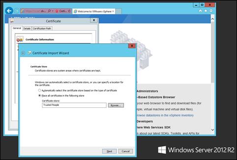
9. Click Next and then click Finish.
10. Perform the above steps on all Delivery Controllers and Provisioning Servers.
Install XenDesktop Delivery Controller, Citrix Licensing and StoreFront
The process of installing the XenDesktop Delivery Controller also installs other key XenDesktop software components, including Studio, which is used to create and manage infrastructure components, and Director, which is used to monitor performance and troubleshoot problems.
1. To begin the installation, connect to the first XenDesktop server and launch the installer from the Citrix XenDesktop 7.7 ISO.
2. Click Start

The installation wizard presents a menu with three subsections.
3. Click “Get Started - Delivery Controller.”
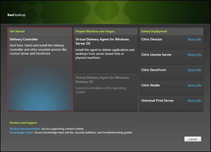
4. Read the Citrix License Agreement.
5. If acceptable, indicate your acceptance of the license by selecting the “I have read, understand, and accept the terms of the license agreement” radio button.
6. Click Next
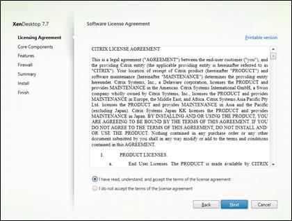
7. Select the components to be installed on the first Delivery Controller Server:
a. Delivery Controller
b. Studio
c. License Server
d. StoreFront
8. Click Next
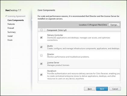
9. Since a SQL Server will be used to Store the Database, leave “Install Microsoft SQL Server 2012 SP1 Express” unchecked.
10. Click Next
11. Select the default ports and automatically configured firewall rules.
12. Click Next
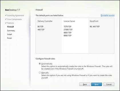
13. Click Install to begin the installation.
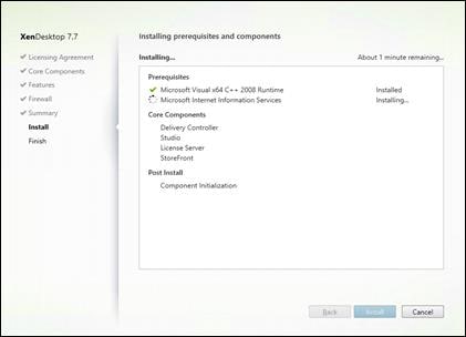
14. Click Finish
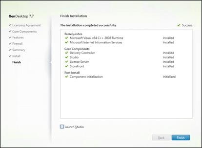
15. (Optional) Check Launch Studio to launch Citrix Studio Console.
Installing Citrix Licenses
To install the Citrix Licenses, complete the following steps:
1. Copy the license files to the default location (C:\Program Files (x86)\Citrix\Licensing\ MyFiles) on the license server.
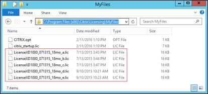
2. Restart the server or Citrix licensing services so that the licenses are activated.
3. Run the application Citrix License Administration Console.
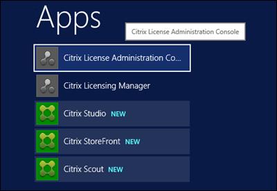
4. Confirm that the license files have been read and enabled correctly.
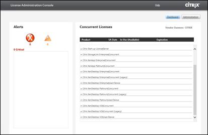
Configure the XenDesktop Site
Citrix Studio is a management console that allows you to create and manage infrastructure and resources to deliver desktops and applications. Replacing Desktop Studio from earlier releases, it provides wizards to set up your environment, create workloads to host applications and desktops, and assign applications and desktops to users.
Citrix Studio launches automatically after the XenDesktop Delivery Controller installation, or if necessary, it can be launched manually. Studio is used to create a Site, which is the core XenDesktop 7.7 environment consisting of the Delivery Controller and the Database.
To configure XenDesktop, complete the following steps:
1. From Citrix Studio, click the Deliver applications and desktops to your users button.
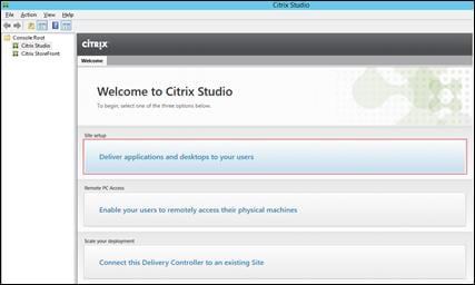
2. Select the “An empty, unconfigured Site” radio button.
3. Enter a site name.
4. Click Next
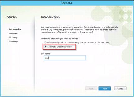
5. Provide the Database Server Locations for each data type and click Next.
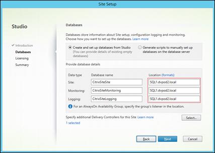
6. Provide the FQDN of the license server.
7. Click Connect to validate and retrieve any licenses from the server.
![]() If no licenses are available, you can use the 30-day free trial or activate a license file.
If no licenses are available, you can use the 30-day free trial or activate a license file.
8. Select the appropriate product edition using the license radio button
9. Click Next
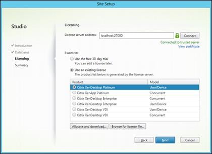
10. Click Finish to complete initial setup.
![]() High availability will be available for the databases once added to the SQL AlwaysOn Availability Group
High availability will be available for the databases once added to the SQL AlwaysOn Availability Group
11. Click Test site to determine the site creation success.
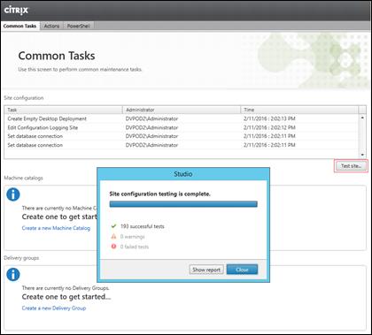
Additional XenDesktop Controller Configuration
After the first controller is completely configured and the Site is operational, you can add additional controllers. In this CVD, we created two Delivery Controllers.
To configure additional XenDesktop controllers, complete the following steps:
1. To begin the installation of the second Delivery Controller, connect to the second XenDesktop server and launch the installer from the Citrix XenDesktop 7.7 ISO.
2. Click Start
3. Click Delivery Controller
4. Select the components to be installed:
5. Delivery Controller
a. Studio
b. Director
c. StoreFront (This solution uses two dedicated StoreFront servers)
6. Click Next
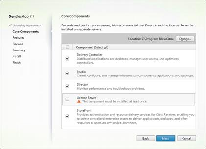
7. Repeat the same steps used to install the first Delivery Controller, including the step of importing an SSL certificate for HTTPS between the controller and vSphere.
8. Review the Summary configuration.
9. Click Install
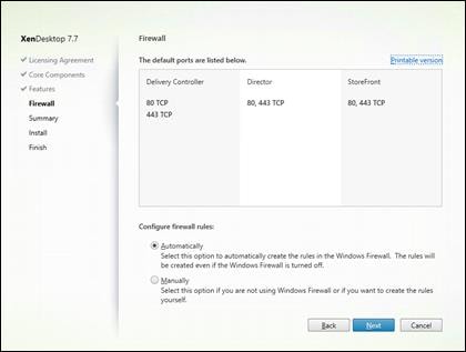
10. Confirm all selected components were successfully installed.
11. Verify the Launch Studio checkbox is checked.
12. Click Finish
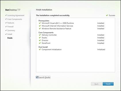
Add the Second Delivery Controller to the XenDesktop Site
To add the second Delivery Controller to the XenDesktop Site, complete the following steps:
1. Click the Connect this Delivery Controller to an existing Site button.
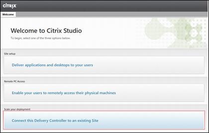
2. Enter the FQDN of the first delivery controller.
3. Click OK
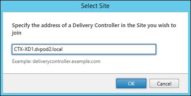
4. Click Yes to allow the database to be updated with this controller’s information automatically.
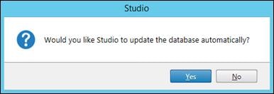
5. When complete, verify the Delivery Controller has been added to the list of Controllers.
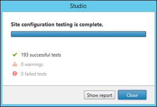
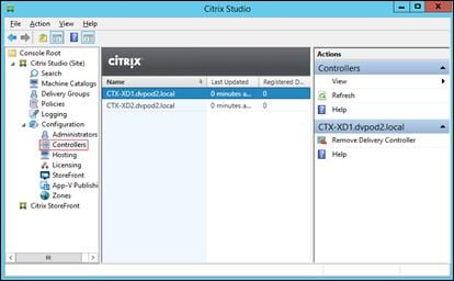
Create Host Connections with Citrix Studio
Citrix Studio provides wizards to guide the process of setting up an environment and creating desktops. To set up a host connection for a cluster of VMs for the HSD and VDI desktops, complete the following steps:
![]() The instructions below outline the procedure to add a host connection and resources for HSD and VDI desktops.
The instructions below outline the procedure to add a host connection and resources for HSD and VDI desktops.
1. Connect to the XenDesktop server and launch Citrix Studio.
2. From the Configuration menu, right-click Hosting and select Add Connection and Resources.
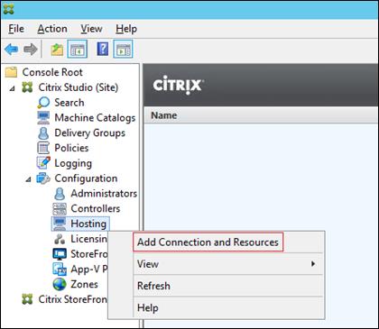
3. Select the Host Type of VMware vSphere®.
4. Enter the FQDN of the vCenter server.
5. Enter the username (in domain\username format) for the vSphere account.
6. Provide the password for the vSphere account.
7. Provide a connection name.
8. Select the Other tools radio button since Provisioning Services will be used.
9. Click Next.
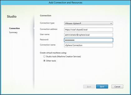
10. Review the Summary.
11. Click Finish
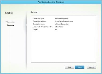
Configuring StoreFront
Citrix StoreFront stores aggregate desktops and applications from XenDesktop sites, making resources readily available to users. In this CVD, StoreFront is installed on the Delivery Controllers virtual machine as part of the initial Delivery Controller installation. Most of the StoreFront configuration is automatically done as part of the installer. To finalize the StoreFront configuration log into the second Delivery Controller and launch the StoreFront Console.
To configure StoreFront, complete the following steps:
1. From the StoreFront Console on the second server select “Join existing server group”.
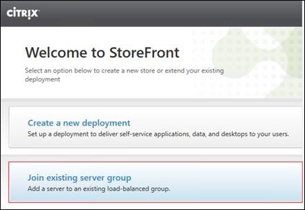
2. In the Join Server Group dialog, enter the name of the first Storefront server.
3. Before the additional StoreFront server can join the server group, you must connect to the first Storefront server, add the second server, and obtain the required authorization information.
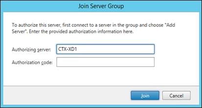
4. Connect to the first StoreFront server.
5. Using the StoreFront menu on the left, you can scroll through the StoreFront management options.
6. Select Server Group from the menu.
7. At this point, the Server Group contains a single Storefront server.
8. Select Generate Security Keys from the Actions menu on the right. Security keys are needed for signing and encryption.
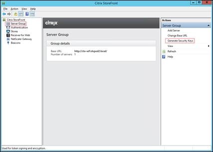
9. Click Generate Keys.
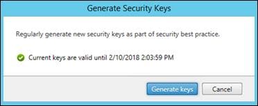
10. Select Server Group from the menu.
11. To generate the authorization information that allows the additional StoreFront server to join the server group, select Add Server.
12. Copy the Authorization code from the Add Server dialog.
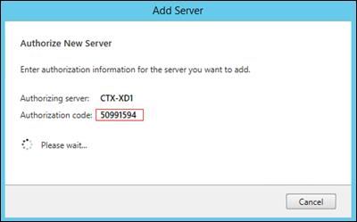
13. Connect to the second Storefront server and paste the Authorization code into the Join Server Group dialog.
14. Click Join
15. A message appears when the second server has joined successfully.
16. Click OK
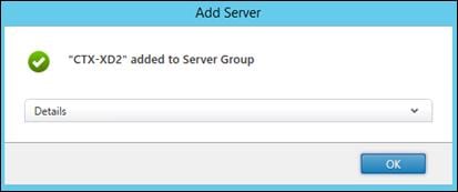
17. The Server Group now lists both StoreFront servers in the group.
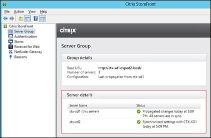
Installing and Configuring Citrix Provisioning Server 7.7
In most implementations, there is a single vDisk providing the standard image for multiple target devices. Thousands of target devices can use a single vDisk shared across multiple Provisioning Services (PVS) servers in the same farm, simplifying virtual desktop management. This section describes the installation and configuration tasks required to create a PVS implementation.
The PVS server can have many stored vDisks, and each vDisk can be several gigabytes in size. Your streaming performance and manageability can be improved using a RAID array, SAN, or NAS. PVS software and hardware requirements are available at: http://docs.citrix.com/en-us/provisioning/7-7.html
Prerequisites
Set the following Scope Options on the DHCP server hosting the PVS target machines (for example, VDI, RDS).
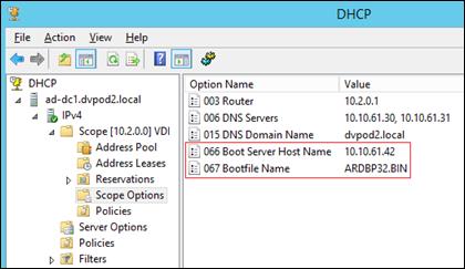
As a Citrix best practice cited in this CTX article, apply the following registry setting both the PVS servers and target machines:
HKEY_LOCAL_MACHINE\SYSTEM\CurrentControlSet\Services\TCPIP\Parameters\
Key: "DisableTaskOffload" (dword)
Value: "1"
Only one MS SQL database is associated with a farm. You can choose to install the Provisioning Services database software on an existing SQL database, if that machine can communicate with all Provisioning Servers within the farm, or with a new SQL Express database machine, created using the SQL Express software that is free from Microsoft.
The following MS SQL 2008, MS SQL 2008 R2, MS SQL 2012, MS SQL 2012 R2 and MS SQL 2014 Server (32 or 64-bit editions) databases can be used for the Provisioning Services database: SQL Server Express Edition, SQL Server Workgroup Edition, SQL Server Standard Edition, SQL Server Enterprise Edition. Microsoft SQL 2012 R2 was installed separately for this CVD.
To install and configure Citrix Provisioning Service 7.7, complete the following steps:
1. Insert the Citrix Provisioning Services 7.7 ISO and let AutoRun launch the installer.
2. Click the Console Installation button.
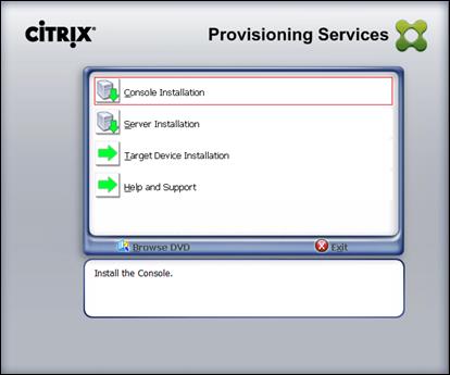
3. Click Install to install the required prerequisites.
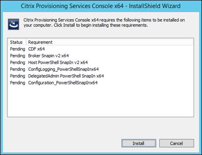
4. Click Next
5. Read the Citrix License Agreement.
6. If acceptable, select the radio button labeled “I accept the terms in the license agreement.”
7. Click Next
8. Optionally provide User Name and Organization.
9. Click Next
10. Accept the default path.
11. Click Next
12. Click Install to start the console installation.
13. From the main installation screen, select Server Installation.
14. The installation wizard will check to resolve dependencies and then begin the PVS server installation process.
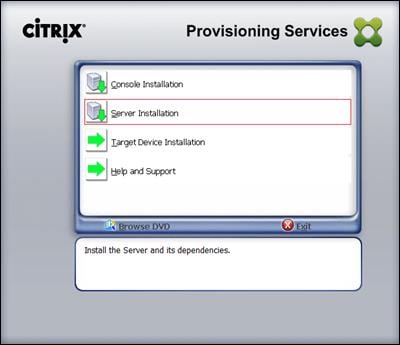
15. Click Install on the prerequisites dialog.
16. Click Yes when prompted to install the SQL Native Client.
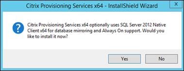
17. Click Next when the Installation wizard starts.
18. Review the license agreement terms.
19. If acceptable, select the radio button labeled “I accept the terms in the license agreement.”
20. Click Next
21. Provide User Name, and Organization information. Select who will see the application.
22. Click Next
23. Accept the default installation location.
24. Click Next
25. Click Install to begin the installation.
26. Click Finish when the install is complete.
27. The PVS Configuration Wizard starts automatically.
28. Click Next
29. Since the PVS server is not the DHCP server for the environment, select the radio button labeled, “The service that runs on another computer.”
30. Click Next
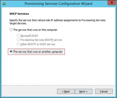
31. Since DHCP boot options 66 and 67 are used for TFTP services, select the radio button labeled, “The service that runs on another computer.”
32. Click Next
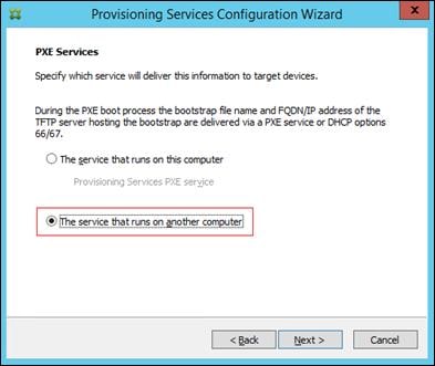
33. Since this is the first server in the farm, select the radio button labeled, “Create farm”.
34. Click Next
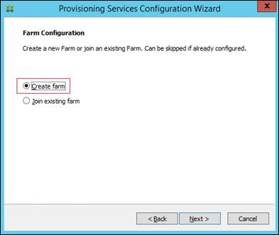
35. Enter the FQDN of the SQL server.
36. Click Next
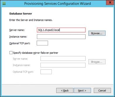
37. Provide the Database, Farm, Site, and Collection names.
38. Click Next
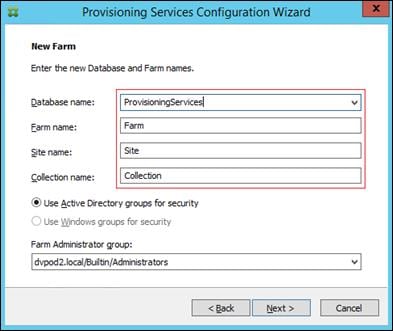
39. Provide a vDisk Store name and the storage path to the NetApp vDisk share.
![]() Create the share using NetApp’s native support for SMB3.
Create the share using NetApp’s native support for SMB3.
40. Click Next
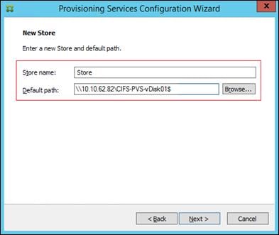
41. Provide the FQDN of the license server.
42. Optionally, provide a port number if changed on the license server.
43. Click Next
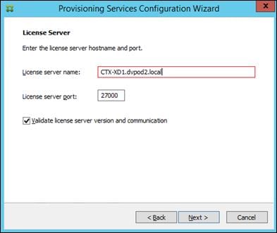
44. If an Active Directory service account is not already setup for the PVS servers, create that account prior to clicking Next on this dialog.
45. Select the Specified user account radio button.
46. Complete the User name, Domain, Password, and Confirm password fields, using the PVS account information created earlier.
47. Click Next

48. Set the Days between password updates to 7.
![]() This will vary per environment. “7 days” for the configuration was appropriate for testing purposes.
This will vary per environment. “7 days” for the configuration was appropriate for testing purposes.
49. Click Next
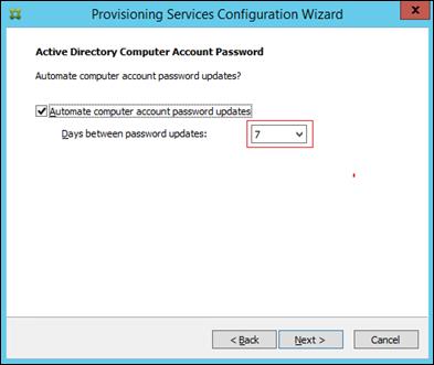
50. Keep the defaults for the network cards.
51. Click Next
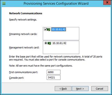
52. Select Use the Provisioning Services TFTP service checkbox.
53. Click Next
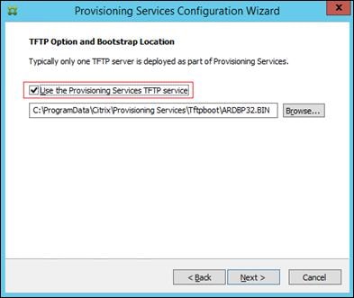
54. Make sure that the IP Addresses for all PVS servers are listed in the Stream Servers Boot List
55. Click Next
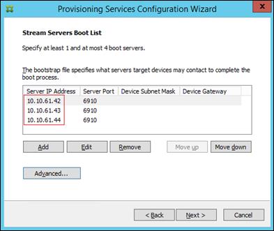
56. Click Finish to start installation.
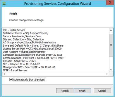
57. When the installation is completed, click Done.
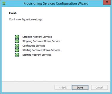
Install Additional PVS Servers
Complete the installation steps on the additional PVS servers up to the configuration step where it asks to Create or Join a farm. In this CVD, we repeated the procedure to add a total of three PVS servers. To install additional PVS servers, complete the following steps:
1. On the Farm Configuration dialog, select “Join existing farm.”
2. Click Next
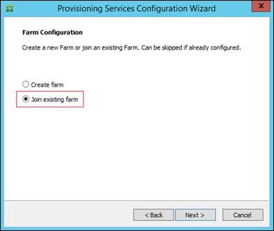
3. Provide the FQDN of the SQL Server.
4. Click Next
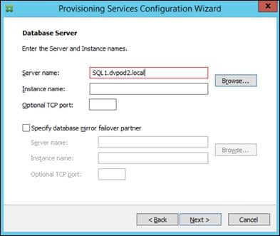
5. Accept the Farm Name.
6. Click Next
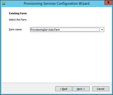
7. Accept the Existing Site.
8. Click Next
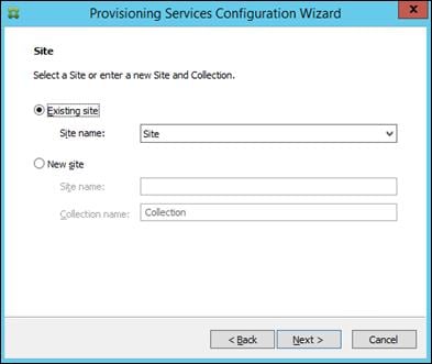
9. Accept the existing vDisk store.
10. Click Next
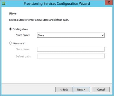
11. Provide the PVS service account information.
12. Click Next
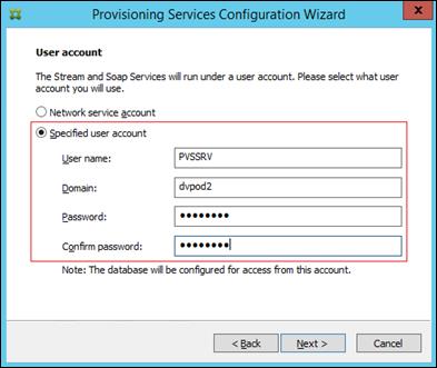
13. Set the Days between password updates to 7.
14. Click Next
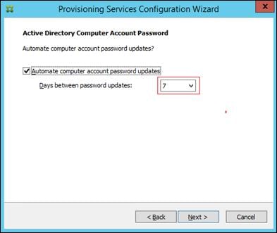
15. Accept the network card settings.
16. Click Next
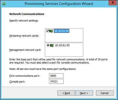
17. Select Use the Provisioning Services TFTP service checkbox.
18. Click Next
19. Make sure that the IP Addresses for all PVS servers are listed in the Stream Servers Boot List
20. Click Next
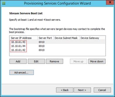
21. Click Finish to start the installation process.
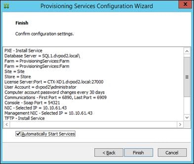
22. Click Done when the installation finishes.
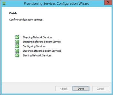
![]() You can optionally install the Provisioning Services console on the second PVS server following the procedure in the section Installing Provisioning Services.
You can optionally install the Provisioning Services console on the second PVS server following the procedure in the section Installing Provisioning Services.
![]() After completing the steps to install the second PVS server, launch the Provisioning Services Console to verify that the PVS Servers and Stores are configured and that DHCP boot options are defined.
After completing the steps to install the second PVS server, launch the Provisioning Services Console to verify that the PVS Servers and Stores are configured and that DHCP boot options are defined.
23. Launch Provisioning Services Console and select Connect to Farm
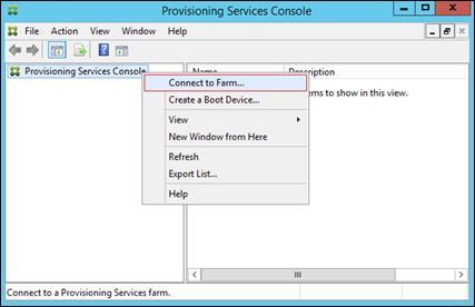
24. Enter localhost for the PVS1 server
25. Click Connect
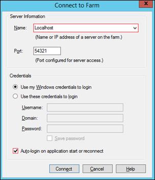
26. Select Store Properties from the drop-down menu
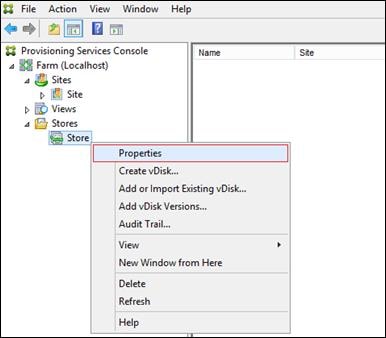
27. In the Store Properties dialog, add the Default store path to the list of Default write cache paths.
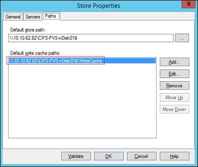
28. Click Validate. If the validation is successful, click OK to continue.
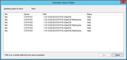
Install XenDesktop Virtual Desktop Agents
Virtual Delivery Agents (VDAs) are installed on the server and workstation operating systems, and enable connections for desktops and apps. The following procedure was used to install VDAs for both HVD and HSD environments.
By default, when you install the Virtual Delivery Agent, Citrix User Profile Management is installed silently on master images. (Using profile management as a profile solution is optional but was used for this CVD, and is described in a later section.)
To install XenDesktop Virtual Desktop Agents, complete the following steps:
1. Launch the XenDesktop installer from the XenDesktop 7.7 ISO.
2. Click Start on the Welcome Screen.
3. To install the VDA for the Hosted Virtual Desktops (VDI), select Virtual Delivery Agent for Windows Desktop OS. After the VDA is installed for Hosted Virtual Desktops, repeat the procedure to install the VDA for Hosted Shared Desktops (RDS). In this case, select Virtual Delivery Agent for Windows Server OS and follow the same basic steps.
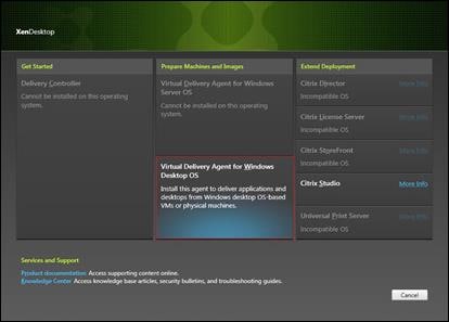
4. Select “Create a Master Image”.
5. Click Next
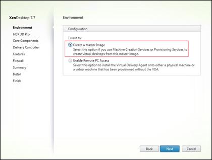
6. For the VDI vDisk, select “No, install the standard VDA”.
7. Click Next
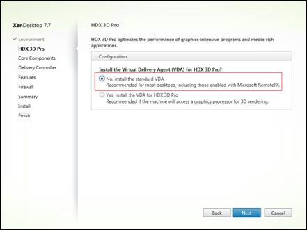
8. Optional: Select Citrix Receiver.
9. Click Next
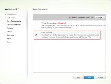
10. Select “Do it manually” and specify the FQDN of the Delivery Controllers.
11. Click Next
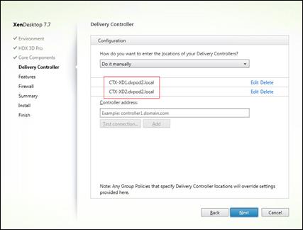
12. Accept the default features.
13. Click Next
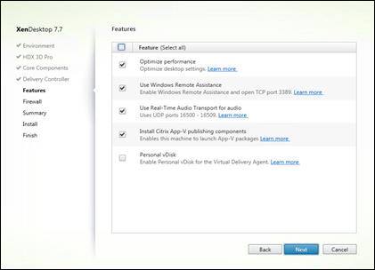
14. Allow the firewall rules to be configured Automatically.
15. Click Next
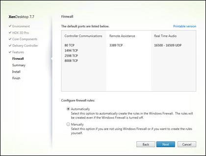
16. Verify the Summary and click Install.
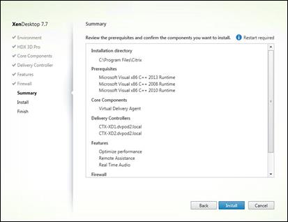
17. Check “Restart Machine”.
18. Click Finish and the machine will reboot automatically.
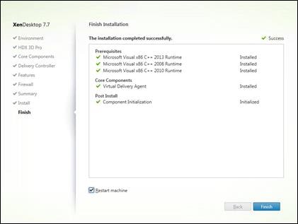
![]() Repeat the procedure so that VDAs are installed for both VDI (using the Windows 7 OS image) and the RDS desktops (using the Windows Server 2012 R2 image).
Repeat the procedure so that VDAs are installed for both VDI (using the Windows 7 OS image) and the RDS desktops (using the Windows Server 2012 R2 image).
Install the Citrix Provisioning Server Target Device Software
The Master Target Device refers to the target device from which a hard disk image is built and stored on a vDisk. Provisioning Services then streams the contents of the vDisk created to other target devices. This procedure installs the PVS Target Device software that is used to build the RDS and VDI golden images.
To install the Citrix Provisioning Server Target Device software, complete the following steps:
![]() The instructions below outline the installation procedure to configure a vDisk for VDI desktops. When you have completed these installation steps, repeat the procedure to configure a vDisk for RDS.
The instructions below outline the installation procedure to configure a vDisk for VDI desktops. When you have completed these installation steps, repeat the procedure to configure a vDisk for RDS.
1. On the Window 7 Master Target Device, install Microsoft hotfix KB2550978.
2. Click Yes to install.
![]() This step only applies to Windows 7.
This step only applies to Windows 7.
3. Restart the machine when the installation is complete.
4. Launch the PVS installer from the Provisioning Services 7.7 ISO.
5. Click the Target Device Installation button.
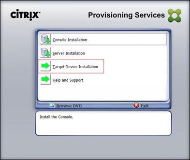
![]() The installation wizard will check to resolve dependencies and then begin the PVS target device installation process.
The installation wizard will check to resolve dependencies and then begin the PVS target device installation process.
6. Click Next.
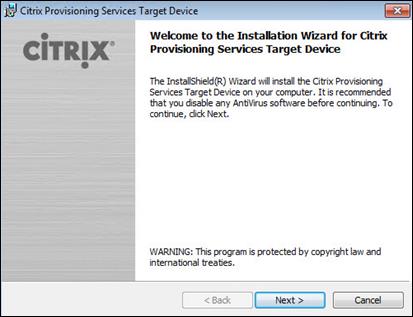
7. Confirm the installation settings and click Install.
8. Deselect the checkbox to launch the Imaging Wizard and click Finish.
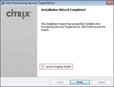
9. Reboot the machine.
Create Citrix Provisioning Server vDisks
The PVS Imaging Wizard automatically creates a base vDisk image from the master target device. To create the Citrix Provisioning Server vDisks, complete the following steps:
![]() The instructions below describe the process of creating a vDisk for VDI desktops. When you have completed these steps, repeat the procedure to build a vDisk for RDS.
The instructions below describe the process of creating a vDisk for VDI desktops. When you have completed these steps, repeat the procedure to build a vDisk for RDS.
1. The PVS Imaging Wizard's Welcome page appears.
2. Click Next
3. The Connect to Farm page appears. Enter the name or IP address of a Provisioning Server within the farm to connect to and the port to use to make that connection.
4. Use the Windows credentials (default) or enter different credentials.
5. Click Next
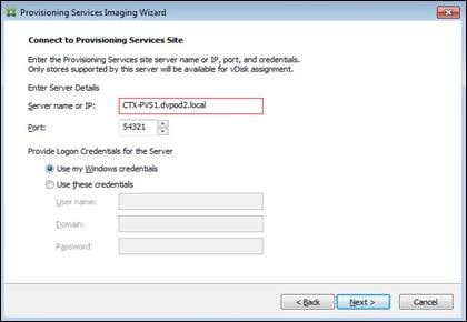
6. Select Create new vDisk.
7. Click Next
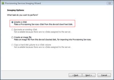
8. The Add Target Device page appears.
9. Select the Target Device Name, the MAC address associated with one of the NICs that was selected when the target device software was installed on the master target device, and the Collection to which you are adding the device.
10. Click Next
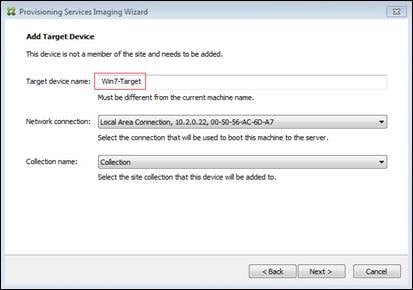
11. The New vDisk dialog displays. Enter the name of the vDisk.
12. Select the Store where the vDisk will reside. Select the vDisk type, either Fixed or Dynamic, from the drop-down menu. (This CVD used Dynamic rather than Fixed vDisks.)
13. Click Next
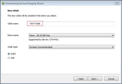
14. On the Microsoft Volume Licensing page, select the volume license option to use for target devices. For this CVD, volume licensing is not used, so the None button is selected.
15. Click Next
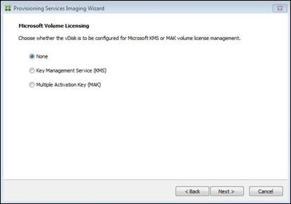
16. Select Image entire boot disk on the Configure Image Volumes page.
17. Click Next
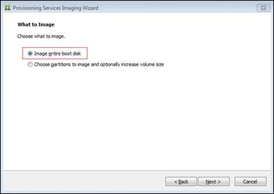
18. Select Optimize for hard disk again for Provisioning Services before imaging on the Optimize Hard Disk for Provisioning Services.
19. Click Next
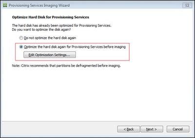
20. Select Create on the Summary page.
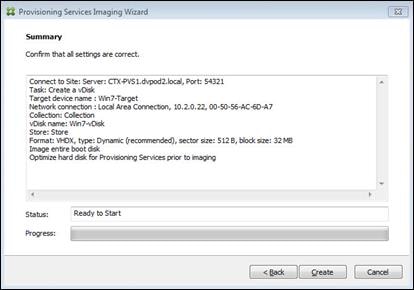
21. Review the configuration and click Continue.
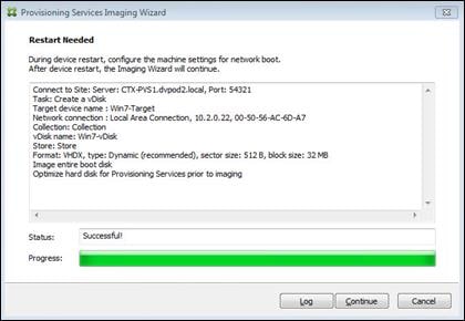
22. When prompted, click No to shut down the machine.
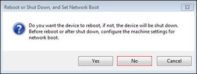
23. Edit the VM settings and select Force BIOS Setup under Boot Options.
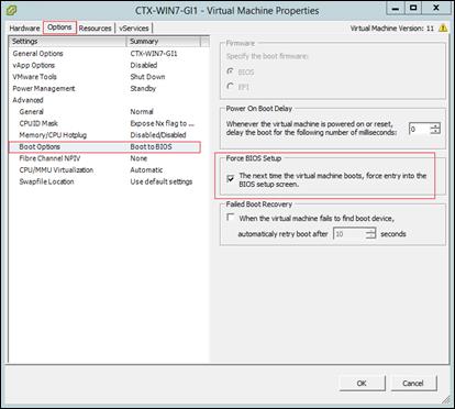
24. Configure the BIOS/VM settings for PXE/network boot, putting Network boot from VMware VMXNET3 at the top of the boot device list.
25. Select Exit Saving Changes.
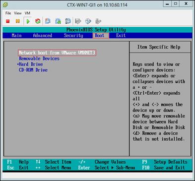
![]() After restarting the VM, log into the VDI or RDS master target. The PVS imaging process begins, copying the contents of the C: drive to the PVS vDisk located on the server.
After restarting the VM, log into the VDI or RDS master target. The PVS imaging process begins, copying the contents of the C: drive to the PVS vDisk located on the server.
26. If prompted to Restart select Restart Later.
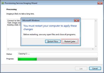
27. A message is displayed when the conversion is complete, click Done.
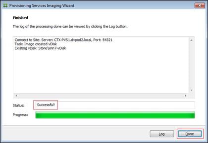
28. Shutdown the VM used as the VDI or RDS master target.
29. Connect to the PVS server and validate that the vDisk image is available in the Store.
30. Right-click the newly created vDisk and select Properties.
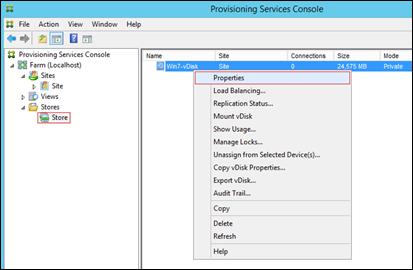
31. On the vDisk Properties dialog, change Access mode to “Standard Image (multi-device, read-only access)”.
32. Set the Cache Type to “Cache in device RAM with overflow on hard disk.”
33. Set Maximum RAM size (MBs): 64 for VDI and set 1024 MB for RDS vDisk.
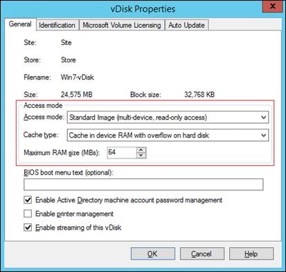
34. Click OK
![]() Repeat this procedure to create vDisks for both the Hosted VDI Desktops (using the Windows 7 OS image) and the Hosted Shared Desktops (using the Windows Server 2012 R2 image).
Repeat this procedure to create vDisks for both the Hosted VDI Desktops (using the Windows 7 OS image) and the Hosted Shared Desktops (using the Windows Server 2012 R2 image).
Provision Virtual Desktop Machines
To create VDI and RDS machines, complete the following steps:
1. Select the Master Target Device VM from the vSphere Client.
2. Right-click the VM and select Clone.
3. Name the cloned VM Desktop-Template.
4. Select the cluster and datastore where the first phase of provisioning will occur.
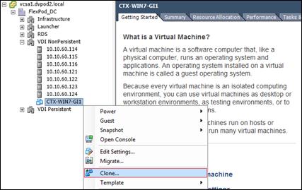
5. Remove Hard disk 1 from the Template VM.
![]() Hard disk 1 is not required to provision desktop machines as the XenDesktop Setup Wizard dynamically creates the write cache disk.
Hard disk 1 is not required to provision desktop machines as the XenDesktop Setup Wizard dynamically creates the write cache disk.
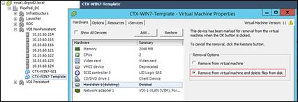
6. Convert to the Desktop-Template VM to a Template.
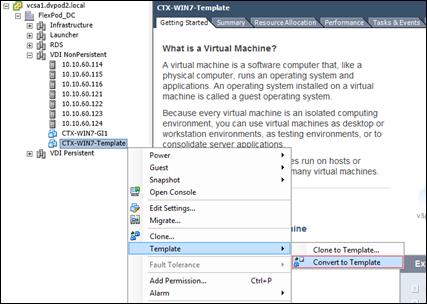
7. From Citrix Studio on the Desktop Controller, select Hosting and Add Connection and Resources.
8. Select Use an existing Connection and click Next.
9. Correspond the name of the resource with desktop machine clusters.
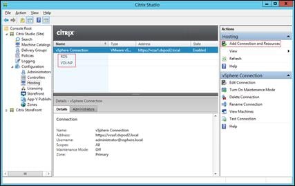
10. Browse and select the vSphere cluster for desktop provisioning.
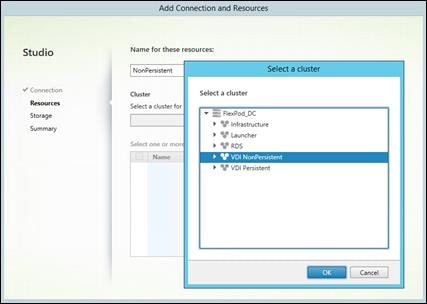
11. Select the VDI networks for the desktop machines and click Next.
12. Select the first datastore for desktop provisioning.
13. Click Finish.
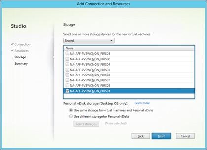
![]() Return to these settings to alter the datastore selection for each set of provisioned desktop machines.
Return to these settings to alter the datastore selection for each set of provisioned desktop machines.
14. Start the XenDesktop Setup Wizard from the Provisioning Services Console.
15. Right-click the Site.
16. Choose XenDesktop Setup Wizard… from the context menu.
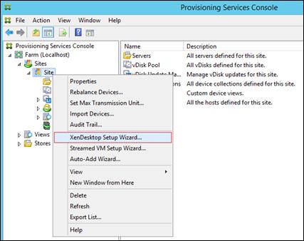
17. Click Next.
18. Enter the XenDesktop Controller address that will be used for the wizard operations.
19. Click Next.
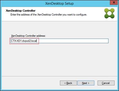
20. Select the Host Resources on which the virtual machines will be created.
21. Click Next
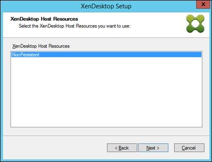
22. Provide the Host Resources Credentials (Username and Password) to the XenDesktop controller when prompted.
23. Click OK
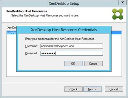
24. Select the Template created earlier.
25. Click Next
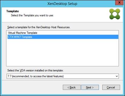
26. Select the network that will be used for the provisioned virtual machines.
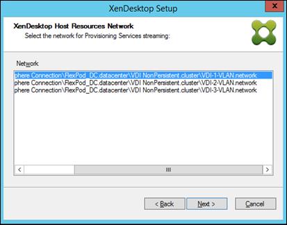
![]() A single VLAN was created for the VDI and RDS VMs, however, the Nexus 1000V is limited to 1024 ports per interface. Three port-profiles where created to accommodate this CVD.
A single VLAN was created for the VDI and RDS VMs, however, the Nexus 1000V is limited to 1024 ports per interface. Three port-profiles where created to accommodate this CVD.
27. Select the vDisk that will be used to stream virtual machines.
28. Click Next
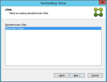
29. Select “Create a new catalog”.
![]() The catalog name is also used as the collection name in the PVS site.
The catalog name is also used as the collection name in the PVS site.
30. Click Next
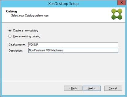
31. On the Operating System dialog, specify the operating system for the catalog. Specify Windows Desktop Operating System for VDI and Windows Server Operating System for RDS.
32. Click Next
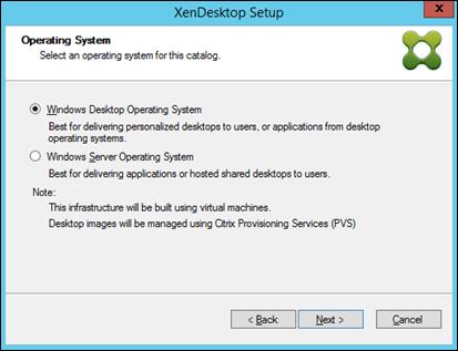
33. If you specified a Windows Desktop OS for VDIs, a User Experience dialog appears. Specify that the user will connect to “A fresh new (random) desktop each time.”
34. Click Next
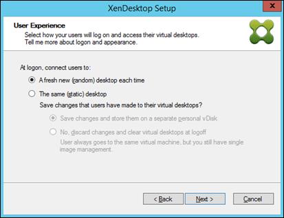
35. On the Virtual machines dialog, specify:
§ The number of VMs to create. (Note that it is recommended to create 200 or less per provisioning run. Create a single VM at first to verify the procedure.)
§ Number of vCPUs for the VM (2 for VDI, 6 for RDS)
§ The amount of memory for the VM (1.7GB for VDI, 24GB for RDS)
§ The write-cache disk size (6GB for VDI, 30GB for RDS)
§ PXE boot as the Boot Mode
36. Click Next
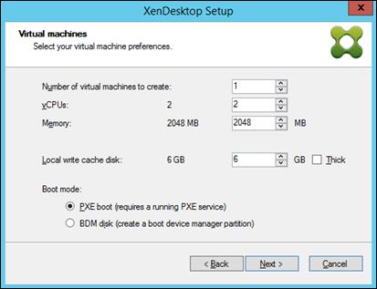
37. Select the Create new accounts radio button.
38. Click Next
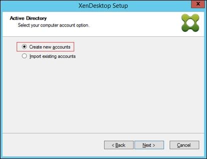
39. Specify the Active Directory Accounts and Location. This is where the wizard should create the computer accounts.
40. Provide the Account naming scheme. An example name is shown in the text box below the name scheme selection location.
41. Click Next
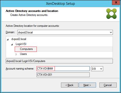
42. Click Finish to begin the virtual machine creation.
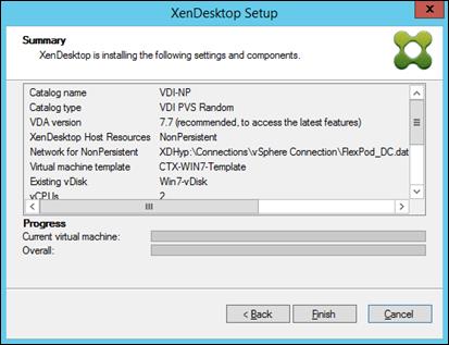
43. When the wizard is done provisioning the virtual machines, click Done.
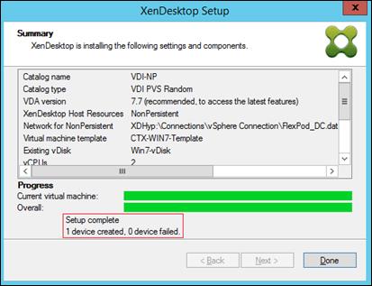
![]() Provisioning process takes ~7 seconds per machine.
Provisioning process takes ~7 seconds per machine.
44. Verify the desktop machines were successfully created in the following locations:
— PVS1 > Provisioning Services Console > Farm > Site > Device Collections > VDI-NP > CTX-VDI-001
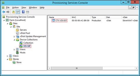
— CTX-XD1 > Citrix Studio > Machine Catalogs > VDI-NP
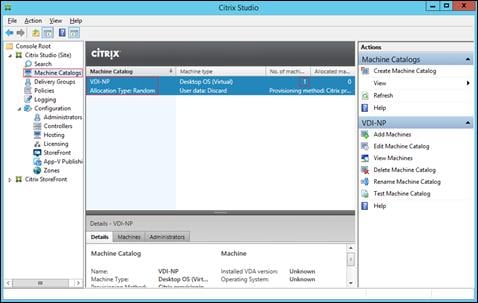
— AD-DC1 > Active Directory Users and Computers > dvpod2.local > ComputerOU > CTX-VDI-001
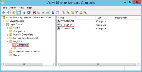
— VCSA > vSphere Client > FlexPod_DC > VDI NonPersistent > CTX-VDI-001
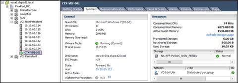
45. Logon to newly provisioned desktop machine, using the Virtual Disk Status verify the image mode is set to Ready Only and the cache type as Device Ram with overflow on local hard drive.
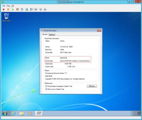
Create Delivery Groups
Delivery Groups are collections of machines that control access to desktops and applications. With Delivery Groups, you can specify which users and groups can access which desktops and applications.
To create delivery groups, complete the following steps:
![]() The instructions below outline the procedure to create a Delivery Group for VDI desktops. When you have completed these steps, repeat the procedure to a Delivery Group for RDS desktops.
The instructions below outline the procedure to create a Delivery Group for VDI desktops. When you have completed these steps, repeat the procedure to a Delivery Group for RDS desktops.
1. Connect to a XenDesktop server and launch Citrix Studio.
2. Choose Create Delivery Group from the drop-down menu.
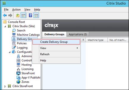
3. Specify the Machine Catalog and increment the number of machines to add.
4. Click Next
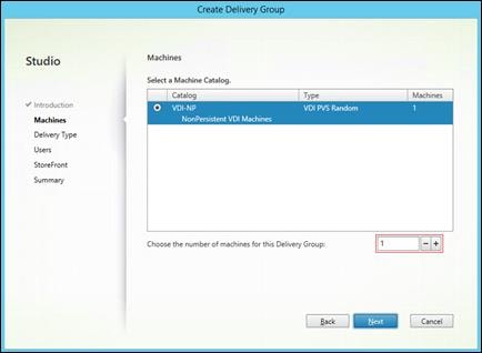
5. Specify what the machines in the catalog will deliver: Desktops, Desktops and Applications, or Applications.
6. Select Desktops.
7. Click Next
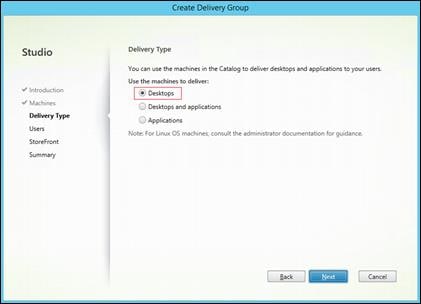
8. To make the Delivery Group accessible, you must add users, click Add…
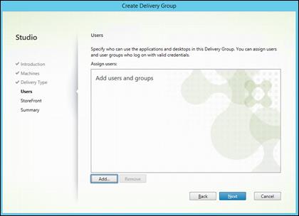
9. In the Select Users or Groups dialog, add users or groups.
10. Click OK. When users have been added, click Next on the Assign dialog (shown above).
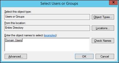
11. Enter the StoreFront configuration for how Receiver will be installed on the machines in this Delivery Group. Click “Manually, using a StoreFront server address that I will provide later.”
12. Click Next
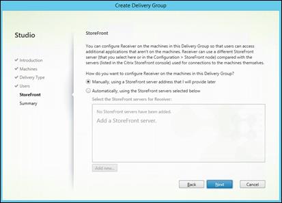
13. On the Summary dialog, review the configuration. Enter a Delivery Group name and a Display name (for example, VDI or RDS).
14. Click Finish
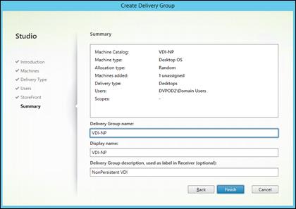
15. Citrix Studio lists the created Delivery Groups and the type, number of machines created, sessions, and applications for each group in the Delivery Groups tab.
16. On the pull-down menu, select “Turn on Maintenance Mode.”
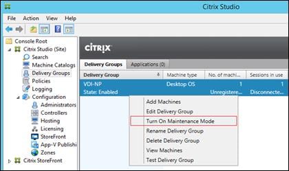
Configure User Profile Manager Share on NetApp AFF8080
Clustered Data ONTAP was introduced to provide more reliability and scalability to the applications and services hosted on Data ONTAP. Windows File Services is one of the key features of clustered Data ONTAP because this software provides services with the Server Message Block (CIFS/SMB) protocol.
SMB 3.0 is a revised version of the SMB 2.x protocol introduced by Microsoft in Windows 8 and Windows Server 2012. SMB 3.0 offers significant enhancements to the SMB protocol in terms of availability, scalability, reliability, and protection.
To set up the CIFS server, you must create an SVM with proper setting for CIFS access, configure DNS on the SVM, create the CIFS server, and, if necessary, set up UNIX user and group name services. For more information on CIFS configuration, see TR-4191: Best Practice Guide for Clustered Data ONTAP 8.2 Windows File Services.
To set up your CIFS server, you must make decisions regarding the SVM, DNS, and CIFS server configurations and record your choices in the planning worksheet prior to creating the configuration. Follow this process for the share called User_Profiles used by Citrix User Profile Manager (UPM).
:> vserver setup
Welcome to the Vserver Setup Wizard, which will lead you through
the steps to create a storage virtual machine that serves data to clients.
Step 1. Create a Vserver.
Enter the Vserver name: CIFS
Choose the Vserver data protocols to be configured {nfs, cifs, fcp, iscsi}:
cifs
Choose the Vserver client services to be configured {ldap, nis, dns}:
dns
Enter the Vserver's root volume aggregate { aggr0_R4E08NA3250_02, DATA_R4E08NA3250_02}
[DATA_R4E08NA3250_02]: DATA_R4E08NA3250_02
Enter the Vserver language setting, or "help" to see all languages [C]: en-us
Enter the Vserver root volume's security style {unix, ntfs, mixed} [unix]:
ntfs
Vserver creation might take some time to finish….Vserver vDisk with language set to C created. The permitted protocols are cifs.
Step 2: Create a data volume
You can type "back", "exit", or "help" at any question.
Do you want to create a data volume? {yes, no} [yes]: yes
Enter the volume name [vol1]: User_Profiles
Enter the name of the aggregate to contain this volume { aggr0_R4E08NA3250_02, DATA_R4E08NA3250_02} [DATA_R4E08NA3250_02]: DATA_R4E08NA3250_02
Enter the volume size: 75GB
Enter the volume junction path [/User_Profiles]:
It can take up to a minute to create a volume…Volume User_Profiles of size 75GB created on aggregate DATA_R4E08NA3250_02 successfully.
Step 3: Create a logical interface.
You can type "back", "exit", or "help" at any question.
Do you want to create a logical interface? {yes, no} [yes]: yes
Enter the LIF name [lif1]: CIFS_User_Profiles
Which protocols can use this interface [cifs]:
Enter the home node { R4E08NA3250-CL-01, R4E08NA3250-CL-02} [R4E08NA3250-CL-02]: R4E08NA3250-CL-02
Enter the home port {a0b, a0b-803, a0b-804} [a0a]:
a0b-803
Enter the IP address: 10.218.241.101
Enter the network mask: 255.255.255.0
Enter the default gateway IP address:
LIF CIFS_User_Profiles on node R4E08NA3250-CL-02, on port a0b-803 with IP address
10.218.241.101 was created.
Do you want to create an additional LIF now? {yes, no} [no]: no
Step 4: Configure DNS (Domain Name Service).
You can type "back", "exit", or "help" at any question.
Do you want to configure DNS? {yes, no} [yes]:
Enter the comma separated DNS domain names: rainier14q1.net
Enter the comma separated DNS server IP addresses: 10.218.241.15
DNS for Vserver CIFS is configured.
Step 5: Configure CIFS.
You can type "back", "exit", or "help" at any question.
Do you want to configure CIFS? {yes, no} [yes]:
Enter the CIFS server name [VDISK]: R4E08NA3250-CL
Enter the Active Directory domain name: rainier14q1.net
In order to create an Active Directory machine account for the CIFS server, you
must supply the name and password of a Windows account with sufficient
privileges to add computers to the "CN=Computers" container within the
"rainier14q1.net" domain.
Enter the user name [administrato]: administrator
Enter the password:
CIFS server "R4E08NA3250-CL" created and successfully joined the domain.
Do you want to share a data volume with CIFS clients? {yes, no} [yes]:
Yes
Enter the CIFS share name [User_Profiles]:
Enter the CIFS share path [/User_Profiles]:
Select the initial level of access that the group "Everyone" has to the share
{No_access, Read, Change, Full_Control} [No_access]: Full_Control
The CIFS share "User_Profiles" created successfully.
Default UNIX users and groups created successfully.
UNIX user "pcuser" set as the default UNIX user for unmapped CIFS users.
Default export policy rule created successfully.
Vserver CIFS, with protocol(s) cifs, and service(s) dns has been
configured successfully.
Creating a CIFS Share for Citrix User Profile Manager (UPM)
Multiple methods to create a CIFS share are supported on NetApp storage. These methods are listed in Section 6.5. For this reference architecture, we used NetApp System Manager to create the profile share. To create the profile share, complete the following steps:
1. Within System Manager, click the SVM menu, select the SVM, and select Storage > Shares in the left window pane. Click Create Share in the right window pane to create the profile share.
2. After clicking the create share menu item, the screen below will appear. Enter the profile folder name in the “Folder to Share” field (includes the Qtree path). The CIFS Share name will be an advertised SMB share name for the profile that will be mapped by a Microsoft Group Policy Object (GPO) during login process. It is a best practice to use a Microsoft hidden share by adding a dollar sign ($) at the end of the share name. This prevents users from seeing the share when browsing the network.
3. Deselect Enable Continuous Availability for Hyer-V and SQL. This check box enables Microsoft Persistent Handles support on the NetApp SMB3 CIFS share. Persistent Handles are not used on normal CIFS shares, but they are used with PVS vDisks.
| Best Practice |
| § Use Microsoft hidden shares by adding a dollar sign ($) at the end of the profile share name. |
Citrix XenDesktop Policies and Profile Management
Policies and profiles allow the Citrix XenDesktop environment to be easily and efficiently customized.
Configure Citrix XenDesktop Policies
Citrix XenDesktop policies control user access and session environments, and are the most efficient method of controlling connection, security, and bandwidth settings. You can create policies for specific groups of users, devices, or connection types with each policy. Policies can contain multiple settings and are typically defined through Citrix Studio. (The Windows Group Policy Management Console can also be used if the network environment includes Microsoft Active Directory and permissions are set for managing Group Policy Objects). The screenshot below shows policies for Login VSI testing in this CVD.
Figure 34 XenDesktop Policy
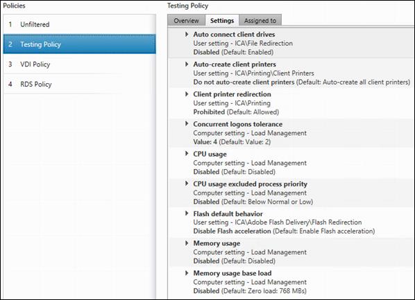
Configuring User Profile Management
Profile management provides an easy, reliable, and high-performance way to manage user personalization settings in virtualized or physical Windows environments. It requires minimal infrastructure and administration, and provides users with fast logons and logoffs. A Windows user profile is a collection of folders, files, registry settings, and configuration settings that define the environment for a user who logs on with a particular user account. These settings may be customizable by the user, depending on the administrative configuration. Examples of settings that can be customized are:
§ Desktop settings such as wallpaper and screen saver
§ Shortcuts and Start menu setting
§ Internet Explorer Favorites and Home Page
§ Microsoft Outlook signature
§ Printers
Some user settings and data can be redirected by means of folder redirection. However, if folder redirection is not used these settings are stored within the user profile.
The first stage in planning a profile management deployment is to decide on a set of policy settings that together form a suitable configuration for your environment and users. The automatic configuration feature simplifies some of this decision-making for XenDesktop deployments. Screenshots of the User Profile Management interfaces that establish policies for this CVD’s RDS and VDI users (for testing purposes) are shown below. Basic profile management policy settings are documented here:
http://docs.citrix.com/en-us/xenapp-and-xendesktop/7-7.html
Figure 35 VDI User Profile Manager Policy
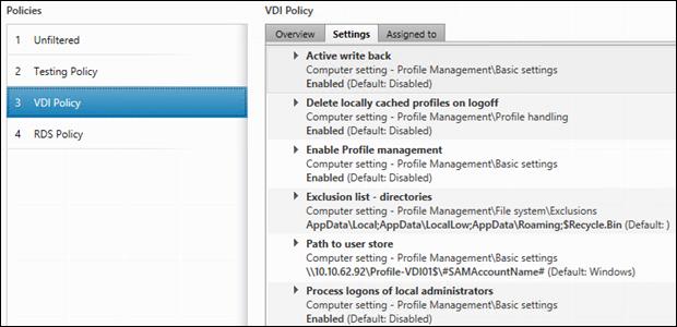
Figure 36 RDS User Profile Manager Policy
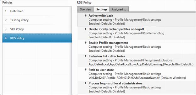
Install and Configure NVIDIA M6 Card
This section focuses on installing and configuring the NVIDIA M6 cards with the Cisco UCS B200 M4 servers to deploy vGPU enabled virtual desktops.
Physical Install of M6 Card into B200 M4 Server
The nVidia M6 graphics processing unit (GPU) provides graphics and computing capabilities to the server. The GPU package consists of the three elements shown in the following figure.
Figure 37 nVidia M6 GPU Package
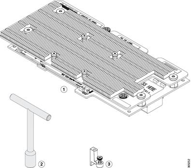
Before You Begin
Before installing the nVidia M6 GPU:
§ Remove any adapter card, such as a VIC 1380, VIC 1280, or PT extender card from slot 2. You cannot use any other card in slot 2 when the nVidia M6 GPU is installed.
§ Upgrade your Cisco UCS system to a version of Cisco UCS Manager that supports this card. Refer to the latest version of the Release Notes for Cisco UCS Software at the following URL for information about supported hardware: http://www.cisco.com/c/en/us/support/servers-unified-computing/ucs-manager/products-release-notes-list.html.
Procedure
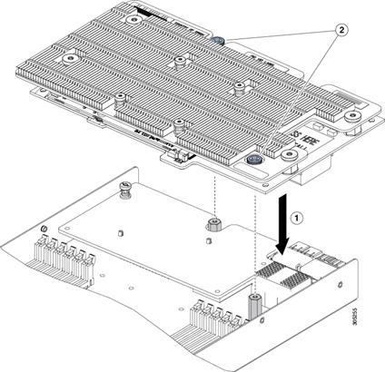
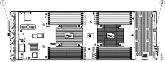
Install the NVIDIA VMware VIB Driver
To install the NVIDIA VMware VIB driver, complete the following steps:
1. From UCS Manager, verify the GPU card has been properly installed.
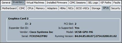
2. Download the latest drivers and software packages from NVidia’s Web Site.
3. Upload the VIB file to the /tmp directory of the ESXi host.
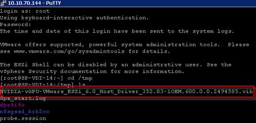
4. Install the latest driver: esxcli software vib install –v /tmp/{Latest Driver Package Name}
![]() Host must be in Maintenance Mode to install.
Host must be in Maintenance Mode to install.
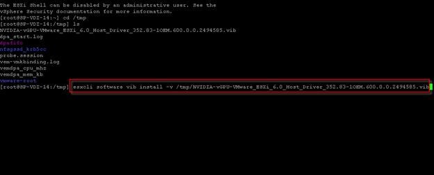
5. A message should validate that the vib installed correctly.
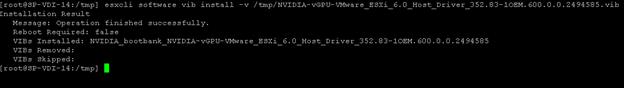
6. Validate the driver was installed by running the command ‘nvidia-smi’ command.
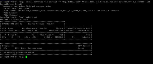
7. By Default the M6 cards come in Compute mode. We will utilize them in Graphics mode in this study. You will need to download the gpumodeswitch utility from NVidia’s web site. In this exercise, we used the boot ISO which loads a Linux environment with the gpumodeswitch utility already loaded.
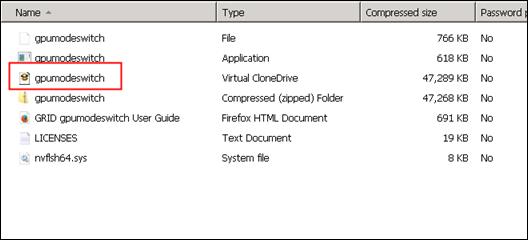
8. Mount the ISO file through the UCSM KVM and reboot the host.
9. When the Linux shell loads, enter the command: gpumodeswitch –gpumode graphics
10. Type ‘Y’ when prompted to switch all adapters to Graphics. When it completes, reboot back into ESXi.
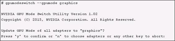
Configure a VM with a vGPU
To configure a vGPU for a VM, complete the following steps:
1. Select ‘Edit Settings’ in the VSphere Web client for the VM you want to add the vGPU
2. Select the ‘Virtual Hardware’ tab
3. In the ‘New device’ section, select ‘Shared PCI Device’ to add the NVIDIA GRID Card
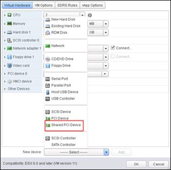
4. Select the GPU Profile you want to run. In this study, we wanted to achieve a density of 16 vGPU machines on this host so we chose Profile ‘grid_m6-0b’ which allocates 512Mb per VM for a total of 16 per blade with the M6 Card.
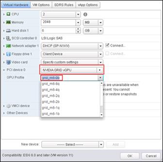
GPU Profiles for the M6 are as follows:

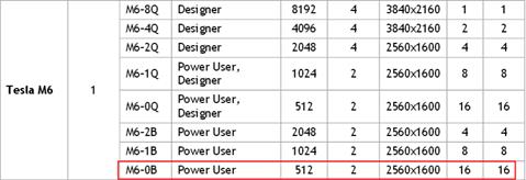
Install the GPU Drivers inside your Windows VM
It is important to note that the drivers installed with the Windows VDI desktop must match the version that accompanies the driver for the ESXi host. So if you downgrade or upgrade the ESXi host vib, you must do the same with the NVIDIA driver in your Windows master image.
In this study we used ESXi Host Driver version 352.83 and 354.80 for the Windows VDI image. These drivers come in the same download package from NVIDIA.
To install the GPU drivers, complete the following steps:
1. Since our image is deployed through Citrix PVS, first place the image in Private Mode.
2. Double-click file ‘354.80_grid_win8_win7_international’
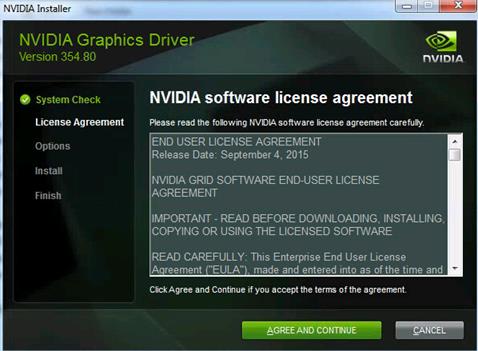
3. Select Agree and Continue
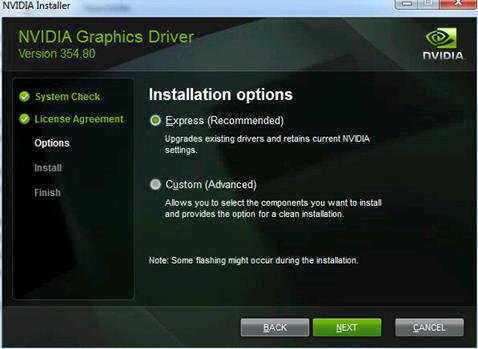
4. Click Next to use Express Installation
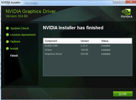
5. The driver and software will be installed and click ‘Finish’ to complete install.
Install and Configure NVIDIA Grid License Server
To use NVIDIA’s vGPU features we must setup a Grid Licensing server. The detailed instructions for setting up a Grid License server can be found in the Grid Quick Start guide. (http://images.nvidia.com/content/grid/pdf/grid-2.0-quick-start-guide.pdf)
The license server requires a fixed IP address. The IP address may be assigned through DHCP or can be statically configured. The server’s Ethernet MAC address is used as a unique identifier when registering the server and generating licenses in NVIDIA’s licensing portal. The server runs on either Windows or Linux.
To create a server interface, complete the following steps:
1. Select Create License Server from under GRID Licensing in the left pane of the NVIDIA Software Licensing Center page to display the Create Server page.
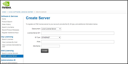
2. Fill in your server details on the Create Server page.
![]() The License Server ID field is the MAC address of the VM of the License server.
The License Server ID field is the MAC address of the VM of the License server.
3. Save the .bin file onto your license server for installation.
![]() Java is required to install the NVIDIA GRID License Server. The package comes in a.zip file.
Java is required to install the NVIDIA GRID License Server. The package comes in a.zip file.
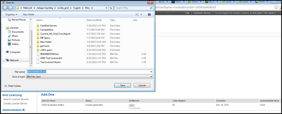
4. Unzip the license server installer.
5. Run setup.exe and follow the installation wizard.
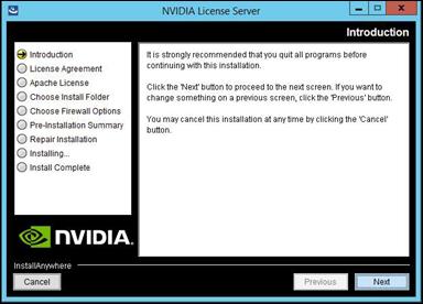
6. Go to http://<FQDN of the license Server>:8080/licserver to display the License Server Configuration page. You will need the License Server’s MAC Address to generate a license .bin file on the portal.
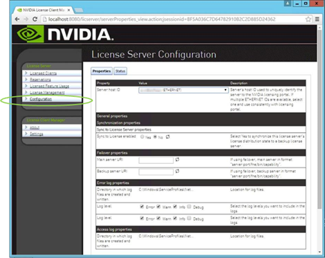
7. Select Configuration from the menu in the left pane.
8. Use the License Server Configuration menu to install the .bin file:
a. Select Choose File.
b. Use the file browser to locate the .bin file downloaded from the licensing portal web site.
9. When the License server is properly installed, we must point our master image to the license server so the VMs with vGPUs can obtain a license.
a. In Windows – Control Panel, double click the NVidia Control Panel.
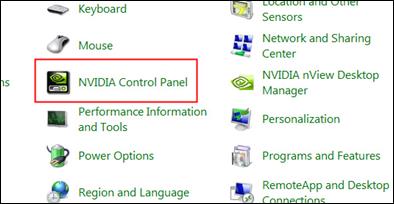
b. In the Control Panel, enter the IP or FQDN of the Grid License Server. You should receive a result similar to the below image.
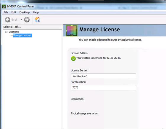
Cisco UCS Performance Manager
Cisco UCS Performance Manager provides visibility from a single console into Cisco UCS components for performance monitoring and capacity planning. It provides data center assurance of integrated infrastructures and ties application performance to physical and virtual infrastructure performance. This allows you to optimize resources and deliver better service levels to your customers.
The release used in this solution features an additional component, Control Center, which is an open-source, application service orchestrator based on Docker.
Control Center greatly simplifies the installation, deployment, and management of Cisco UCS Performance Manager.
This section provides a brief introduction to Control Center, and describes how it affects Cisco UCS Performance Manager deployments.
Installing Cisco UCS Performance Manager
Installing the Control Center Master Host
To install a Cisco UCS Performance Manager appliance package as a Control Center master host, using VMware vSphere, complete the following steps:
1. Download the Cisco UCS Performance Manager OVA file from the Cisco UCS Performance Manager site to your workstation.
2. Use the VMware vSphere Client to log in to vCenter as root, or as a user with superuser privileges, and then display the Home view.
3. From the File menu, select Deploy OVF Template....
4. In the Source panel, specify the path of the Cisco UCS Performance Manager package, and then click Next >.
5. In the OVF Template Details panel, click Next.
6. In the Name and Location panel, provide a name and a location for the server.
a. In the Name field, enter a new name or use the default.
b. In the Inventory Location area, select a data center for the virtual machine.
c. Click Next.
7. In the Host / Cluster panel, select a host system, and then click Next.
8. In the Storage panel, select a storage system with sufficient space for your Cisco system, and then click Next.
9. In the Disk Format panel, select Thin Provision, and then click Next.
10. In the Ready to Complete panel, review the deployment settings, and then click Finish. Please do not check the check box labeled Power on after deployment.
11. Navigate to the new virtual machine's Getting Started tab, and then click the Edit virtual machine settings link.
12. In the Virtual Machine Properties dialog, select Memory in the Hardware table.
13. In the Memory Configuration area, set the Memory Size field to 64GB, and then click the OK button.
14. On the new virtual machine's Getting Started tab, click the Power on virtual machine link.
Configure the Control Center Host Mode
![]() Perform this procedure immediately after creating and starting a Control Center host. All Control Center deployments must include one system configured as the master host.
Perform this procedure immediately after creating and starting a Control Center host. All Control Center deployments must include one system configured as the master host.
To configure the Control Center host mode, complete the following steps:
1. Gain access to the console interface of the Control Center host through your hypervisor console interface.
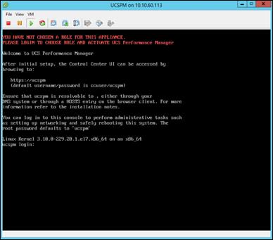
2. Log in as the root user.
3. The initial password is ucspm.
4. The system prompts you to enter a new password for root.
![]() Passwords must include a minimum of eight characters, with at least one character from three of the following character classes: uppercase letter, lowercase letter, digit, and special.
Passwords must include a minimum of eight characters, with at least one character from three of the following character classes: uppercase letter, lowercase letter, digit, and special.
5. The system prompts you to enter a new password for ccuser. The ccuser acount is the default account for gaining access to the Control Center browser interface.
6. Select the master role for the host.
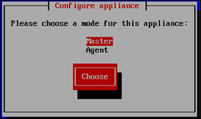
7. In the Configure appliance menu, press the Tab key to select the Choose button.
8. Press the Enter key.
The system will now restart.
Edit a Connection
The default configuration for network connections is DHCP. To configure static IPv4 addressing, complete the following steps:
1. After the systems restarts, login as the root user.
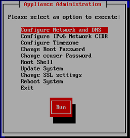
2. Select the NetworkManager TUI menu.
a. In the Appliance Administration menu, select the Configure Network and DNS option.
b. Press the Tab key to select the Run button.
c. Press the Enter key.
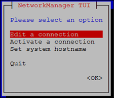
3. On the NetworkManager TUI menu, select Edit a connection, and then press the Return key.
The TUI displays the connections that are available on this host.
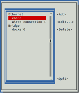
4. Use the down-arrow key to select Wired Connection 1, and then press the Return key.
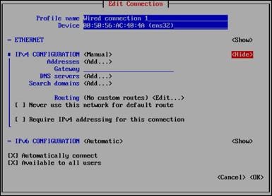
5. Use the Tab key and the arrow keys to navigate among options in the Edit Connection screen, and use the Return key to toggle an option or to display a menu of options.
6. Optional: If the IPv4 CONFIGURATION area is not visible, select its display option (<Show>), and then press the Return key.
7. In the IPv4 CONFIGURATION area, select <Automatic>, and then press the Return key.
8. Configure static IPv4 networking.
a. Use the down arrow key to select Manual, and then press the Return key.
b. Use the Tab key or the down arrow key to select the <Add...> option next to Addresses, and then press
c. the Return key.
d. In the Addresses field, enter an IPv4 address for the virtual machine, and then press the Return key.
e. Repeat the preceding two steps for the Gateway and DNS servers fields.
9. Use the Tab key or the down arrow key to select the <OK> option at the bottom of the Edit Connection screen, and then press the Return key.
10. In the available connections screen, use the Tab key to select the <Quit> option, and then press the Return key.
11. Reboot the operating system.
a. In the Appliance Administration menu, use the down-arrow key to select the Reboot System option.
b. Press the Tab key to select the Run button.
c. Press the Enter key.
Enabling Access to Browser Interfaces
Control Center and Cisco UCS Performance Manager have independent browser interfaces served by independent web servers.
§ The Control Center web server listens at HostnameOrIP:443. So, for a Control Center master host named cc-master.example.com, the hostname-based URL to use is https://cc-master.
§ The Cisco UCS Performance Manager web server listens at a virtual hostname, ucspm.HostnameOrIP:443. For a Control Center master host named cc-master.example.com, the hostname-based URL to use is https://ucspm.cc-master.
To enable access to the browser interfaces by hostname, add name resolution entries to the DNS servers in your environment, or to the hosts files of individual client systems.
§ On Windows client systems, the file is C:\Windows\System32\drivers\etc\hosts.
§ Linux and OS/X client systems, the file is /etc/hosts.
The following line shows the syntax of the entry to add to a name resolution file:
IP-Address FQDN Hostname ucspm.Hostname
For example, the following entry identifies a Control Center master host at IP address 10.24.164.120, hostname cc-master, in the example.com domain.
10.24.164.120 cc-master.example.com cc-master ucspm.cc-master
Deploy Cisco UCS Performance Manager
To log into Control Center for the first time, complete the following steps:
1. Display the login page of the Control Center browser interface.
2. Replace Hostname with the name of the Cisco UCS Performance Manager virtual machine.
https://cc-master.dvpod2.local
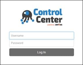
3. At the login page, enter ccuser and its password.
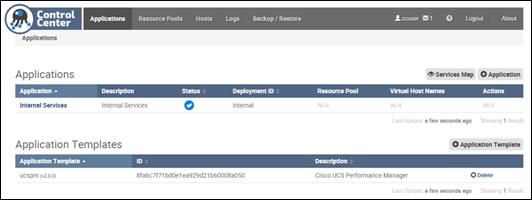
4. On the Applications page, click the + Application button, located at the right side of the page.
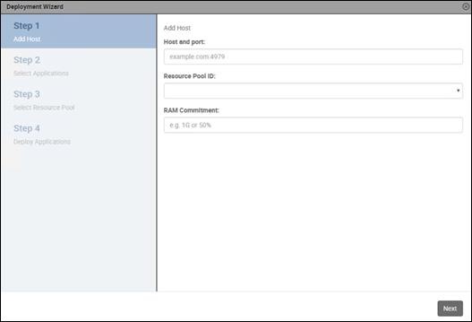
5. In the Deployment Wizard, add the master host to the default resource pool.
The host to add is the Control Center master host.
a. In the Host and Port field, enter the hostname or IP address of the Control Center master host, followed by a colon character (:), and then 4979.
b. If you enter a hostname, all hosts in your Control Center cluster must be able to resolve the name, either through an entry in /etc/hosts, or through a nameserver on your network.
c. In the Resource Pool ID field, select default from the list, and then click Next.
d. In the RAM Committment field, enter the percentage of master host RAM to devote to Control Center and Cisco UCS Performance Manager.
e. The amount of RAM required for the operating system is not included in this value. Cisco recommends entering 100 in the field.
f. At the bottom of the Deployment Wizard, click Next.
6. Select the application to deploy.
a. Select ucspm.
b. At the bottom of the Deployment Wizard, click Next.
7. Select the resource pool for the application.
a. Select default.
b. At the bottom of the Deployment Wizard, click Next.
8. Choose a deployment ID and deploy Cisco UCS Performance Manager.
a. In the Deployment ID field, enter a name for this deployment of Cisco UCS Performance Manager.
b. At the bottom of the Deployment Wizard, click Deploy.
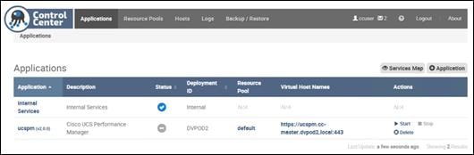
9. At the top of the page, click Logout.
The control is located at the right side of the page.
10. In the Actions column of the Applications table, click the Start control of the ucspm row.
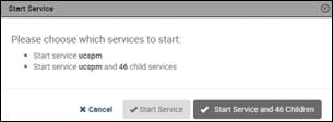
11. In the Start Service dialog, click Start Service and 46 Children button.
12. In the Application column of the Applications table, click ucspm in the ucspm row.
13. Scroll down to watch child services starting.
Typically, child services take 4-5 minutes to start. When no child service shows a red exclamation point icon, Cisco UCS Performance Manager is running.
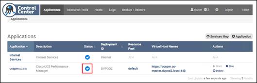
Setting up Cisco UCS Performance Manager
This section describes how to use the Cisco UCS Performance Manager Setup Wizard to accept the end-user license agreement, to provide your license key, define users and passwords, to set up UCS Domains, and to add additional infrastructure.
Initial Setup
After installing Cisco UCS Performance Manager on a virtual machine, and starting it in Control Center, complete the following steps:
1. In a web browser, navigate to the login page of the Cisco UCS Performance Manager interface. Cisco UCS Performance Manager redirects the first login attempt to the Setup page, which includes the End User License Agreement (EULA) dialog.
2. Read through the agreement. At the bottom of the EULA dialog, check the check box on the left side, and then click the Accept License button on the right side.

3. On the Cisco UCS Performance Manager Setup page, click Get Started!
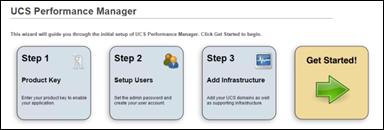
4. On the Add Licenses page, click the Add License File button.
![]() If you do not have your license file yet, you can use the trial version for up to 30 days. You can enter your license file at a later date through the user interface. See the "Product Licensing" section of the Cisco UCS Performance Manager Administration Guide.
If you do not have your license file yet, you can use the trial version for up to 30 days. You can enter your license file at a later date through the user interface. See the "Product Licensing" section of the Cisco UCS Performance Manager Administration Guide.
5. In the Open dialog, select your license file, and then click Open.
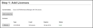
6. Proceed to the next task or repeat the preceding step.
7. In the Set admin password area, enter and confirm a password for the admin user account.
![]() Passwords must contain a minimum of 8 characters, including one capital letter and one digit.
Passwords must contain a minimum of 8 characters, including one capital letter and one digit.
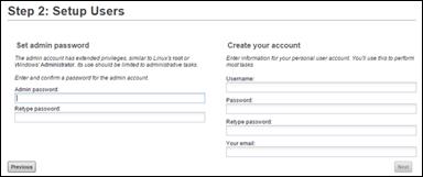
8. In the Create your account area, create one additional administrative user account name and password.
9. Click Next.
Add Cisco UCS Domains
To add the Cisco UCS Domain to Cisco UCS Performance Manager after completing the initial setup configuration, complete the following steps:
1. On the Add UCS Domains page, provide connection credentials for one or more Cisco UCS domains.
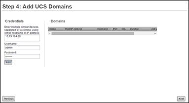
a. In the Enter multiple similar devices, separated by a comma, using either hostname or IP address field, enter the fully-qualified domain name or IP address of a UCS domain server.
b. In the Username field, enter the name of a user account in the UCS domain that is authorized for read access to the resources you plan to monitor.
c. In the Password field, enter the password of the user account specified in the preceding step.
d. Click Add.
2. Review the information in the Status column of the Domains table, and then remove a domain, add a domain, or continue.
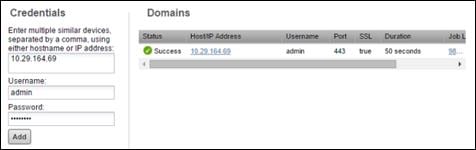
If the final message in the Status column is Failure, click the button in the Remove column, and then try again to add a domain.
If the final message in the Status column is Success, you may add another domain or continue to the next page.
3. Click Next to continue to the Add Infrastructure step.
Adding Infrastructure Devices
Perform this procedure to add the Infrastructure Devices to Cisco UCS Performance Manager after completing the initial setup configuration.
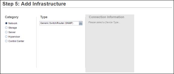
§ This step is optional. Click Finish to exit the Setup Wizard. You will then be taken to the Dashboard.
§ The Setup Wizard times out after 20 minutes if you have not completed it. You may restart Setup Wizard by closing its browser window or tab, and then logging in again. Also, you may add devices through the Add Infrastructure page at any time.
§ As it relates to this solution, other infrastructure devices that can be added include the Cisco Nexus 1000V, NetApp storage using Data ONTAP API (ZAPI), ESXi hosts using SOAP, and Windows Servers using SNMP or WinRM.
Add Nexus 9000 Series Switches
Perform this procedure to add the Infrastructure Devices to Cisco UCS Performance Manager after completing the initial setup configuration.
![]() In order to monitor Cisco Nexus 9000 Series devices, you must first enable NX-API with the feature manager CLI command on the device. For detailed instructions on performing this task, see the following Cisco documentation: http://www.cisco.com/c/en/us/td/docs/switches/datacenter/nexus9000/sw/6-x/programmability/guide/b_Cisco_Nexus_9000_Series_NXOS_Programmability_Guide/b_Cisco_Nexus_9000_Series_NXOS_Programmability_Configuration_Guide_chapter_0101.html#concept_BCCB1EFF9C4A4138BECE9ECC0C4E38DF
In order to monitor Cisco Nexus 9000 Series devices, you must first enable NX-API with the feature manager CLI command on the device. For detailed instructions on performing this task, see the following Cisco documentation: http://www.cisco.com/c/en/us/td/docs/switches/datacenter/nexus9000/sw/6-x/programmability/guide/b_Cisco_Nexus_9000_Series_NXOS_Programmability_Guide/b_Cisco_Nexus_9000_Series_NXOS_Programmability_Configuration_Guide_chapter_0101.html#concept_BCCB1EFF9C4A4138BECE9ECC0C4E38DF
1. In the Category area, select Network.
2. In the Type list, select Cisco Nexus 9000 (SNMP + Netconf).
The protocol used to gather data from the device is included in the list, in parentheses.
3. In the Connection Information area, specify the two 9372 switches to add.
a. In the Enter multiple similar devices, separated by a comma, using either hostname or IP Address field, enter the hostname or IP address of one or more switch or router devices on your network.
b. In the Username or Netconf Username field, enter the name of a user account on the device.
c. In the Password or Netconf Password field, enter the password of the user account specified in the previous field.
d. Click Add.
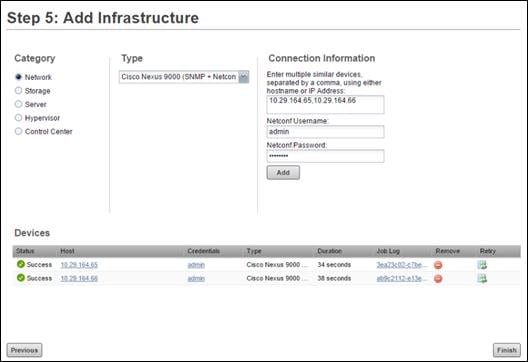
4. When finished adding network devices, click Next.
Cisco UCS Performance Manager Sample Test Data
The following samples represent just some of the useful data that can be obtained using UCS Performance Manager.
The chart shows the network usage from a Fabric Interconnect uplink vPC to a Nexus 9372 switch (Fabric A) during the virtual machine boot storm. All RDS and VDI VMs pertaining to the 5,000 user environment where started in a 15 minute period.
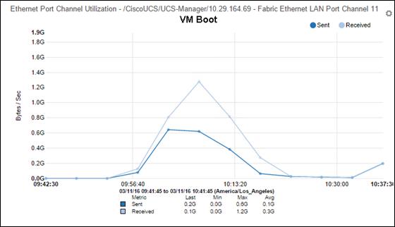
The chart shows the network usage from the NetApp AFF8080EX physical ethernet port (1 of 4 ports per fabric members of a NFS vPC) to a Nexus 9372 switch (Fabric A) during a Login VSI testing. This was a full scale mixed user test run.
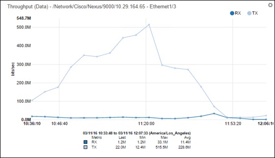
Test Setup and Configurations
In this solution, we tested a single UCS B200 M4 blade to validate against the performance of one blade and twenty-eight B200 M4 blades across four chassis to illustrate linear scalability for each workload use case studied.
Cisco UCS Test Configuration for Single Blade Scalability
This test case validates each workload on a single blade to determine the Recommended Maximum Workload per host server using XenApp/XenDesktop 7.7 with 240 RDS sessions, 195 VDI Non-Persistent sessions, and 195 VDI Persistent sessions.
Figure 40 Cisco UCS B200 M4 Blade Server for Single Server Scalability XenApp 7.7 RDS with PVS 7.7
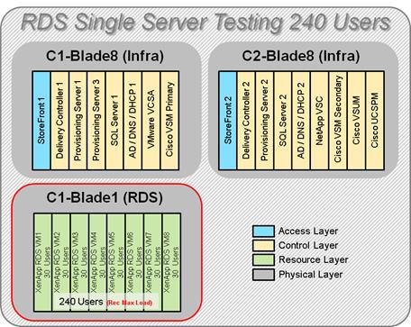
Figure 41 Cisco UCS B200 M4 Blade Server for Single Server Scalability XenDesktop 7.7 VDI (Non-Persistent) with PVS 7.7
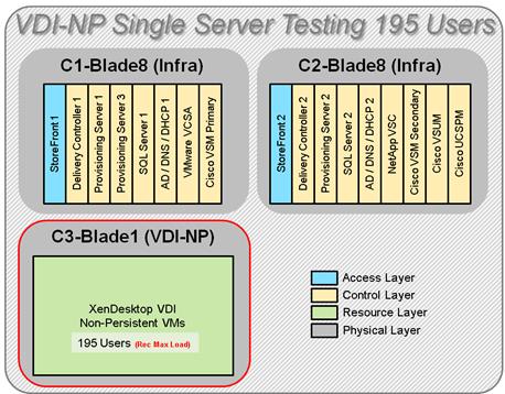
Figure 42 Cisco UCS B200 M4 Blade Server for Single Server Scalability XenDesktop 7.7 VDI (Persistent) with NetApp VSC
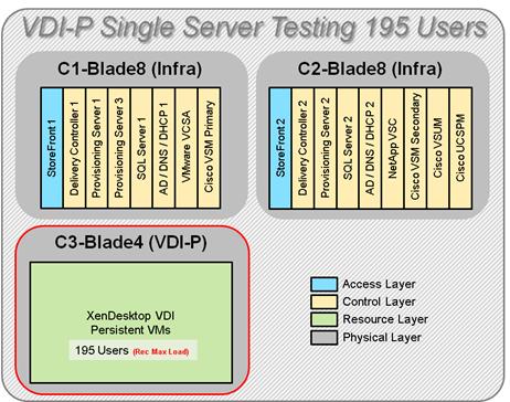
Hardware components:
§ Cisco UCS 5108 Blade Server Chassis
§ 2 Cisco UCS 6248 Fabric Interconnects
§ 2 (Infrastructure Hosts) Cisco UCS B200 M4 Blade Servers (2 Intel Xeon processor E5-2660 v3 CPUs at 2.6 GHz, with 128GB of memory per blade server [16 GB x 8 DIMMs at 2133 MHz]) for all host blades
§ 1 (RDS/VDI Host) Cisco UCS B200 M4 Blade Servers (2 Intel Xeon processor E5-2680 v3 CPUs at 2.5 GHz, with 384GB of memory per blade server [16 GB x 24DIMMs at 1866 MHz]) for all host blades
§ Cisco VIC 1340 CNA (1 per blade)
§ 2 Cisco Nexus 9372PX Access Switches
§ 1 NetApp AFF8080EX storage system with 2x DS2246 disk shelves, 48x 800GB SSDs
Software components:
§ Cisco UCS firmware 3.1(1e)
§ VMware ESXi 6.0 Update 1a for host blades
§ Citrix XenApp/XenDesktop 7.7 VDI Hosted Virtual Desktops and RDS Hosted Shared Desktops
§ Citrix Provisioning Server 7.7
§ Citrix User Profile Manager
§ Microsoft SQL Server 2012
§ Microsoft Windows 7 SP1 32 bit, 2vCPU, 1.7 GB RAM, 24 GB vdisk
§ Microsoft Windows Server 2012 R2, 6vCPU, 24GB RAM, 40 GB vdisk
§ Microsoft Office 2010
§ Login VSI 4.1.4 Knowledge Worker Workload (Benchmark Mode)
Cisco UCS Configuration for Cluster Testing
This test case validates three workload clusters using XenApp/XenDesktop 7.7 with 2,600 RDS sessions, 1,200 VDI Non-Persistent sessions, and 1,200 VDI Persistent sessions. Server N+1 fault tolerance is factored into this test scenario for each workload and infrastructure cluster.
Figure 43 RDS Cluster Test Configuration with Twelve Blades
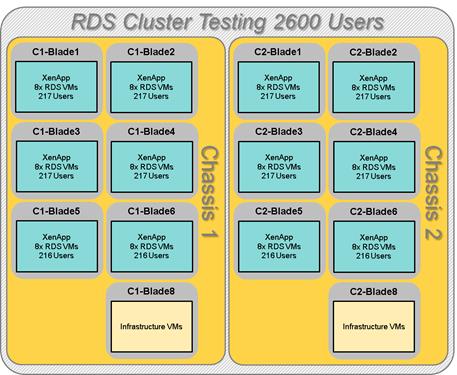
Figure 44 VDI Non-Persistent Cluster Test Configuration with Six Blades
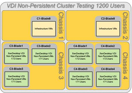
Figure 45 VDI Persistent Cluster Test Configuration with Six Blades

Hardware components:
§ Cisco UCS 5108 Blade Server Chassis
§ 2 Cisco UCS 6248 Fabric Interconnects
§ 2 (Infrastructure Hosts) Cisco UCS B200 M4 Blade Servers (2 Intel Xeon processor E5-2660 v3 CPUs at 2.6 GHz, with 128GB of memory per blade server [16 GB x 8 DIMMs at 2133 MHz]) for infrastructure host blades
§ 28 Cisco UCS B200 M4 Blade Servers (2 Intel Xeon processor E5-2680 v3 CPUs at 2.5 GHz, with 384GB of memory per blade server [16 GB x 24DIMMs at 1866 MHz]) for workload host blades
§ Cisco VIC 1340 CNA (1 per blade)
§ 2 Cisco Nexus 9372PX Access Switches
§ 1 NetApp AFF8080EX storage system with 2x DS2246 disk shelves, 48x 800GB SSDs
Software components:
§ Cisco UCS firmware 3.1(1e)
§ VMware ESXi 6.0 Update 1a for host blades
§ Citrix XenApp/XenDesktop 7.7 VDI Hosted Virtual Desktops and RDS Hosted Shared Desktops
§ Citrix Provisioning Server 7.7
§ Citrix User Profile Manager
§ Microsoft SQL Server 2012
§ Microsoft Windows 7 SP1 32 bit, 2vCPU, 1.7 GB RAM, 24 GB vdisk
§ Microsoft Windows Server 2012 R2, 6vCPU, 24GB RAM, 40 GB vdisk
§ Microsoft Office 2010
§ Login VSI 4.1.4 Knowledge Worker Workload (Benchmark Mode)
Cisco UCS Configuration for Full Scale Testing
This test case validates twenty-eight blades mixed workloads using XenApp/XenDesktop 7.7 with 2,600 RDS sessions, 1,200 VDI Non-Persistent sessions, and 1,200 VDI Persistent sessions for a total sum of 5,000 users. Server N+1 fault tolerance is factored into this solution for each workload and infrastructure cluster.
Figure 46 Full Scale Test Configuration with Twenty-Eight Blades

Hardware components:
§ Cisco UCS 5108 Blade Server Chassis
§ 2 Cisco UCS 6248 Fabric Interconnects
§ 2 (Infrastructure Hosts) Cisco UCS B200 M4 Blade Servers (2 Intel Xeon processor E5-2660 v3 CPUs at 2.6 GHz, with 128GB of memory per blade server [16 GB x 8 DIMMs at 2133 MHz]) for infrastructure host blades
§ 28 Cisco UCS B200 M4 Blade Servers (2 Intel Xeon processor E5-2680 v3 CPUs at 2.5 GHz, with 384GB of memory per blade server [16 GB x 24DIMMs at 1866 MHz]) for workload host blades
§ Cisco VIC 1340 CNA (1 per blade)
§ 2 Cisco Nexus 9372PX Access Switches
§ 1 NetApp AFF8080EX storage system with 2x DS2246 disk shelves, 48x 800GB SSDs
Software components:
§ Cisco UCS firmware 3.1(1e)
§ VMware ESXi 6.0 Update 1a for host blades
§ Citrix XenApp/XenDesktop 7.7 VDI Hosted Virtual Desktops and RDS Hosted Shared Desktops
§ Citrix Provisioning Server 7.7
§ Citrix User Profile Manager
§ Microsoft SQL Server 2012
§ Microsoft Windows 7 SP1 32 bit, 2vCPU, 1.7 GB RAM, 24 GB vdisk
§ Microsoft Windows Server 2012 R2, 6vCPU, 24GB RAM, 40 GB vdisk
§ Microsoft Office 2010
§ Login VSI 4.1.4 Knowledge Worker Workload (Benchmark Mode)
Testing Methodology and Success Criteria
All validation testing was conducted on-site within the Cisco labs in San Jose, California.
The testing results focused on the entire process of the virtual desktop lifecycle by capturing metrics during the desktop boot-up, user logon and virtual desktop acquisition (also referred to as ramp-up,) user workload execution (also referred to as steady state), and user logoff for the Citrix XenApp and XenDesktop Hosted Virtual Desktop and RDS Hosted Shared models under test.
Test metrics were gathered from the hypervisor, virtual desktop, storage, and load generation software to assess the overall success of an individual test cycle. Each test cycle was not considered passing unless all of the planned test users completed the ramp-up and steady state phases (described below) and unless all metrics were within the permissible thresholds as noted as success criteria.
Three successfully completed test cycles were conducted for each hardware configuration and results were found to be relatively consistent from one test to the next.
You can obtain additional information and a free test license from http://www.loginvsi.com.
Testing Procedure
The following protocol was used for each test cycle in this study to insure consistent results.
Pre-Test Setup for Single and Multi-Blade Testing
All virtual machines were shut down utilizing the XenDesktop Administrator and vCenter.
All Launchers for the test were shut down. They were then restarted in groups of 10 each minute until the required number of launchers was running with the Login VSI Agent at a “waiting for test to start” state.
All VMware ESXi VDI host blades to be tested were restarted prior to each test cycle.
Test Run Protocol
To simulate severe, real-world environments, Cisco requires the log-on and start-work sequence, known as Ramp Up, to complete in 48 minutes. Additionally, we require all sessions started, whether 195 single server users or 600 full scale test users to become active within two minutes after the last session is launched.
In addition, Cisco requires that the Login VSI Benchmark method is used for all single server and scale testing. This assures that our tests represent real-world scenarios. For each of the three consecutive runs on single server tests, the same process was followed. Complete the following steps:
1. Time 0:00:00 Start PerfMon/Esxtop/XenServer Logging on the following systems:
a. Infrastructure and VDI Host Blades used in test run
b. SCVMM/vCenter used in test run
c. All Infrastructure VMs used in test run (AD, SQL, brokers, image mgmt., etc.)
2. Time 0:00:10 Start Storage Partner Performance Logging on Storage System
3. Time 0:05: Boot Virtual Desktops/RDS Virtual Machines using XenDesktop Studio or View Connection server.
![]() The boot rate should be around 10-12 VMs per minute per server.
The boot rate should be around 10-12 VMs per minute per server.
4. Time 0:06 First machines boot
5. Time 0:30 Single Server or Scale target number of desktop VMs booted on 1 or more blades
![]() No more than 30 minutes for boot up of all virtual desktops is allowed.
No more than 30 minutes for boot up of all virtual desktops is allowed.
6. Time 0:35 Single Server or Scale target number of desktop VMs desktops registered on XD Studio or available on View Connection Server
7. Virtual machine settling time.
![]() No more than 60 Minutes of rest time is allowed after the last desktop is registered on the XD Studio or available in View Connection Server dashboard. Typically a 30 minute rest period for Windows 7 desktops and 15 minutes for RDS VMs is sufficient.
No more than 60 Minutes of rest time is allowed after the last desktop is registered on the XD Studio or available in View Connection Server dashboard. Typically a 30 minute rest period for Windows 7 desktops and 15 minutes for RDS VMs is sufficient.
8. Time 1:35 Start Login VSI 4.1.4 Office Worker Benchmark Mode Test, setting auto-logoff time at 900 seconds, with Single Server or Scale target number of desktop VMs utilizing sufficient number of Launchers (at 20-25 sessions/Launcher)
9. Time 2:23 Single Server or Scale target number of desktop VMs desktops launched (48 minute benchmark launch rate)
10. Time 2:25 All launched sessions must become active
![]() All sessions launched must become active for a valid test run within this window.
All sessions launched must become active for a valid test run within this window.
11. Time 2:40 Login VSI Test Ends (based on Auto Logoff 900 Second period designated above.)
12. Time 2:55 All active sessions logged off
![]() All sessions launched and active must be logged off for a valid test run. The XD Studio or View Connection Dashboard must show that all desktops have been returned to the registered/available state as evidence of this condition being met.
All sessions launched and active must be logged off for a valid test run. The XD Studio or View Connection Dashboard must show that all desktops have been returned to the registered/available state as evidence of this condition being met.
13. Time 2:57 All logging terminated; Test complete
14. Time 3:15 Copy all log files off to archive; Set virtual desktops to maintenance mode through broker; Shutdown all Windows 7 machines
15. Time 3:30 Reboot all hypervisor hosts.
16. Time 3:45 Ready for new test sequence.
Success Criteria
Our “pass” criteria for this testing follows:
Cisco will run tests at a session count level that effectively utilizes the blade capacity measured by CPU utilization, memory utilization, storage utilization, and network utilization. We will use Login VSI to launch version 4.1 Office Worker workloads. The number of launched sessions must equal active sessions within two minutes of the last session launched in a test as observed on the VSI Management console.
The Citrix Desktop Studio be monitored throughout the steady state to make sure of the following:
§ All running sessions report In Use throughout the steady state
§ No sessions move to unregistered, unavailable or available state at any time during steady state
Within 20 minutes of the end of the test, all sessions on all launchers must have logged out automatically and the Login VSI Agent must have shut down. Stuck sessions define a test failure condition.
Cisco requires three consecutive runs with results within +/-1% variability to pass the Cisco Validated Design performance criteria. For white papers written by partners, two consecutive runs within +/-1% variability are accepted. (All test data from partner run testing must be supplied along with proposed white paper.)
We will publish Cisco Validated Designs with our recommended workload following the process above and will note that we did not reach a VSImax dynamic in our testing. FlexPod Data Center with Cisco UCS Mini and Citrix XenApp/XenDesktop 7.7 on VMware ESXi 6.0 Update 1 Test Results
The purpose of this testing is to provide the data needed to validate Citrix XenApp Hosted Shared Desktop (RDS) and Citrix XenDesktop Hosted Virtual Desktop (VDI) models with Citrix Provisioning Services 7.7 using ESXi and vCenter to virtualize Microsoft Windows 7 SP1 desktops and Microsoft Windows Server 2012 R2 sessions on Cisco UCS B200 M4 Blade Servers using a NetApp AFF8080EX storage system.
The information contained in this section provides data points that a customer may reference in designing their own implementations. These validation results are an example of what is possible under the specific environment conditions outlined here, and do not represent the full characterization of Citrix products with VMware vSphere.
Four test sequences, each containing three consecutive test runs generating the same result, were performed to establish single blade performance and multi-blade, linear scalability.
VSImax 4.1.x Description
The philosophy behind Login VSI is different to conventional benchmarks. In general, most system benchmarks are steady state benchmarks. These benchmarks execute one or multiple processes, and the measured execution time is the outcome of the test. Simply put: the faster the execution time or the bigger the throughput, the faster the system is according to the benchmark.
Login VSI is different in approach. Login VSI is not primarily designed to be a steady state benchmark (however, if needed, Login VSI can act like one). Login VSI was designed to perform benchmarks for SBC or VDI workloads through system saturation. Login VSI loads the system with simulated user workloads using well known desktop applications like Microsoft Office, Internet Explorer and Adobe PDF reader. By gradually increasing the amount of simulated users, the system will eventually be saturated. Once the system is saturated, the response time of the applications will increase significantly. This latency in application response times show a clear indication whether the system is (close to being) overloaded. As a result, by nearly overloading a system it is possible to find out what its true maximum user capacity is.
After a test is performed, the response times can be analyzed to calculate the maximum active session/desktop capacity. Within Login VSI this is calculated as VSImax. When the system is coming closer to its saturation point, response times will rise. When reviewing the average response time it will be clear the response times escalate at saturation point.
This VSImax is the “Virtual Session Index (VSI)”. With Virtual Desktop Infrastructure (VDI) and Terminal Services (RDS) workloads this is valid and useful information. This index simplifies comparisons and makes it possible to understand the true impact of configuration changes on hypervisor host or guest level.
Server-Side Response Time Measurements
It is important to understand why specific Login VSI design choices have been made. An important design choice is to execute the workload directly on the target system within the session instead of using remote sessions. The scripts simulating the workloads are performed by an engine that executes workload scripts on every target system, and are initiated at logon within the simulated user’s desktop session context.
An alternative to the Login VSI method would be to generate user actions client side through the remoting protocol. These methods are always specific to a product and vendor dependent. More importantly, some protocols simply do not have a method to script user actions client side.
For Login VSI the choice has been made to execute the scripts completely server side. This is the only practical and platform independent solution, for a benchmark like Login VSI.
Calculating VSImax v4.1.x
The simulated desktop workload is scripted in a 48 minute loop when a simulated Login VSI user is logged on, performing generic Office worker activities. After the loop is finished it will restart automatically. Within each loop the response times of sixteen specific operations are measured in a regular interval: sixteen times in within each loop. The response times of these five operations are used to determine VSImax.
The five operations from which the response times are measured are:
§ Notepad File Open (NFO)
Loading and initiating VSINotepad.exe and opening the openfile dialog. This operation is handled by the OS and by the VSINotepad.exe itself through execution. This operation seems almost instant from an end-user’s point of view.
§ Notepad Start Load (NSLD)
Loading and initiating VSINotepad.exe and opening a file. This operation is also handled by the OS and by the VSINotepad.exe itself through execution. This operation seems almost instant from an end-user’s point of view.
§ Zip High Compression (ZHC)
This action copy's a random file and compresses it (with 7zip) with high compression enabled. The compression will very briefly spike CPU and disk IO.
§ Zip Low Compression (ZLC)
This action copy's a random file and compresses it (with 7zip) with low compression enabled. The compression will very briefly disk IO and creates some load on the CPU.
§ CPU
Calculates a large array of random data and spikes the CPU for a short period of time.
These measured operations within Login VSI do hit considerably different subsystems such as CPU (user and kernel), Memory, Disk, the OS in general, the application itself, print, GDI, etc. These operations are specifically short by nature. When such operations become consistently long: the system is saturated because of excessive queuing on any kind of resource. As a result, the average response times will then escalate. This effect is clearly visible to end-users. If such operations consistently consume multiple seconds the user will regard the system as slow and unresponsive.
Figure 47 Sample of a VSI max response time graph, representing a normal test

Figure 48 Sample of a VSI test response time graph where there was a clear performance issue

When the test is finished, VSImax can be calculated. When the system is not saturated, and it could complete the full test without exceeding the average response time latency threshold, VSImax is not reached and the amount of sessions ran successfully.
The response times are very different per measurement type, for instance Zip with compression can be around 2800 ms, while the Zip action without compression can only take 75ms. These response time of these actions are weighted before they are added to the total. This ensures that each activity has an equal impact on the total response time.
In comparison to previous VSImax models, this weighting much better represent system performance. All actions have very similar weight in the VSImax total. The following weighting of the response times are applied.
The following actions are part of the VSImax v4.1 calculation and are weighted as follows (US notation):
§ Notepad File Open (NFO): 0.75
§ Notepad Start Load (NSLD): 0.2
§ Zip High Compression (ZHC): 0.125
§ Zip Low Compression (ZLC): 0.2
§ CPU: 0.75
This weighting is applied on the baseline and normal Login VSI response times.
With the introduction of Login VSI 4.1 we also created a new method to calculate the basephase of an environment. With the new workloads (Taskworker, Powerworker, etc.) enabling 'basephase' for a more reliable baseline has become obsolete. The calculation is explained below. In total 15 lowest VSI response time samples are taken from the entire test, the lowest 2 samples are removed and the 13 remaining samples are averaged. The result is the Baseline. In short:
§ Take the lowest 15 samples of the complete test
§ From those 15 samples remove the lowest 2
§ Average the 13 results that are left is the baseline
The VSImax average response time in Login VSI 4.1.x is calculated on the amount of active users that are logged on the system.
Always a 5 Login VSI response time samples are averaged + 40 percent of the amount of “active” sessions. For example, if the active sessions is 60, then latest 5 + 24 (=40 percent of 60) = 31 response time measurement are used for the average calculation.
To remove noise (accidental spikes) from the calculation, the top 5 percent and bottom 5 percent of the VSI response time samples are removed from the average calculation, with a minimum of 1 top and 1 bottom sample. As a result, with 60 active users, the last 31 VSI response time sample are taken. From those 31 samples the top 2 samples are removed and lowest 2 results are removed (5 percent of 31 = 1.55, rounded to 2). At 60 users the average is then calculated over the 27 remaining results.
VSImax v4.1.x is reached when the VSIbase + a 1000 ms latency threshold is not reached by the average VSI response time result. Depending on the tested system, VSImax response time can grow 2 - 3x the baseline average. In end-user computing, a 3x increase in response time in comparison to the baseline is typically regarded as the maximum performance degradation to be considered acceptable.
In VSImax v4.1.x this latency threshold is fixed to 1000ms, this allows better and fairer comparisons between two different systems, especially when they have different baseline results. Ultimately, in VSImax v4.1.x, the performance of the system is not decided by the total average response time, but by the latency is has under load. For all systems, this is now 1000ms (weighted).
The threshold for the total response time is: average weighted baseline response time + 1000ms.
When the system has a weighted baseline response time average of 1500ms, the maximum average response time may not be greater than 2500ms (1500+1000). If the average baseline is 3000 the maximum average response time may not be greater than 4000ms (3000+1000).
When the threshold is not exceeded by the average VSI response time during the test, VSImax is not hit and the amount of sessions ran successfully. This approach is fundamentally different in comparison to previous VSImax methods, as it was always required to saturate the system beyond VSImax threshold.
Lastly, VSImax v4.1.x is now always reported with the average baseline VSI response time result. For example: “The VSImax v4.1 was 125 with a baseline of 1526ms”. This helps considerably in the comparison of systems and gives a more complete understanding of the system. The baseline performance helps to understand the best performance the system can give to an individual user. VSImax indicates what the total user capacity is for the system. These two are not automatically connected and related:
When a server with a very fast dual core CPU, running at 3.6 GHZ, is compared to a 10 core CPU, running at 2,26 GHZ, the dual core machine will give and individual user better performance than the 10 core machine. This is indicated by the baseline VSI response time. The lower this score is, the better performance an individual user can expect.
However, the server with the slower 10 core CPU will easily have a larger capacity than the faster dual core system. This is indicated by VSImax v4.1.x, and the higher VSImax is, the larger overall user capacity can be expected.
With Login VSI 4.1.x a new VSImax method is introduced: VSImax v4.1. This methodology gives much better insight in system performance and scales to extremely large systems.
Single-Server Recommended Maximum Workload
For both the Citrix XenDesktop 7.7 Hosted Virtual Desktop and Citrix XenApp 7.7 RDS Hosted Shared Desktop use cases, a recommended maximum workload was determined that was based on both Login VSI Medium workload with flash end user experience measures and blade server operating parameters.
This recommended maximum workload approach allows you to determine the server N+1 fault tolerance load the blade can successfully support in the event of a server outage for maintenance or upgrade.
Our recommendation is that the Login VSI Average Response and VSI Index Average should not exceed the Baseline plus 2000 milliseconds to insure that end user experience is outstanding. Additionally, during steady state, the processor utilization should average no more than 90-95%. (Memory should never be oversubscribed for Desktop Virtualization workloads.)
Callouts have been added throughout the data charts to indicate each phase of testing.
| Test Phase | Description |
| Boot | Start all RDS and VDI virtual machines at the same time |
| Logon | The Login VSI phase of test is where sessions are launched and start executing the workload over a 48 minutes duration |
| Steady state | The steady state phase is where all users are logged in and performing various workload tasks such as using Microsoft Office, Web browsing, PDF printing, playing videos, and compressing files (typically for 15 minute duration) |
| Logoff | Sessions finish executing the Login VSI workload and logoff |
Test Results
Single-Server Recommended Maximum Workload Testing
This section shows the key performance metrics that were captured on the Cisco UCS host blades during the single server testing to determine the Recommended Maximum Workload per host server. The single server testing comprised of three tests: 240 RDS sessions, 195 VDI Non-Persistent sessions, and 195 VDI Persistent sessions.
Single-Server Recommended Maximum Workload for RDS with 240 Users
Figure 49 Single Server Recommended Maximum Workload for RDS with 240 Users
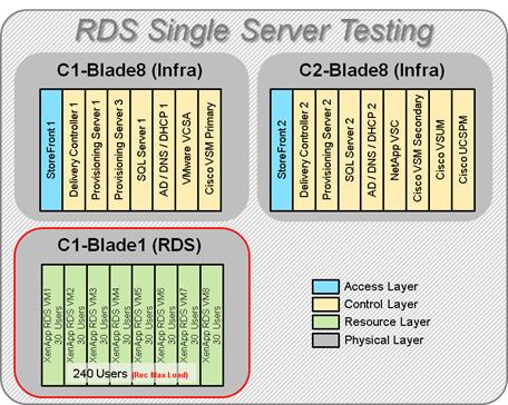
The recommended maximum workload for a B200 M4 blade server with dual E5-2680 v3 processors and 384GB of RAM is 240 Server 2012 R2 Hosted Shared Desktops. Each dedicated blade server ran 8 Server 2012 R2 Virtual Machines. Each virtual server was configured with 6 vCPUs and 24GB RAM.
Figure 50 Single Server | XenApp 7.7 RDS | VSI Score
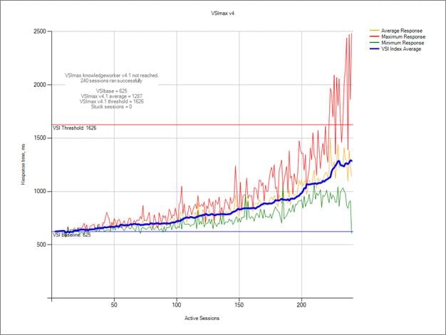
Figure 51 Single Server | XenApp 7.7 RDS | VSI Repeatability
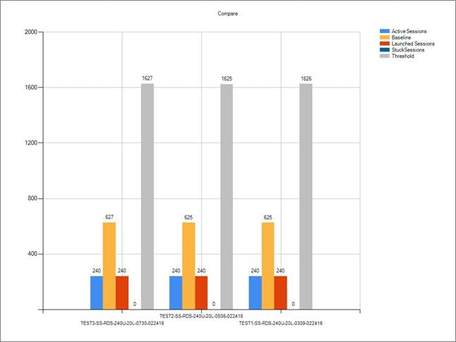
Performance data for the server running the workload follows:
Figure 52 Single Server | XenApp 7.7 RDS | Host CPU Utilization
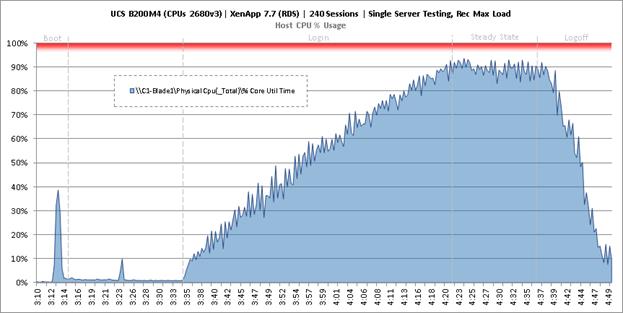
Figure 53 Single Server | XenApp 7.7 RDS | Host Memory Utilization
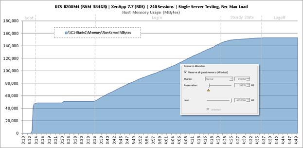
Figure 54 Single Server | XenApp 7.7 RDS | Host Network Utilization
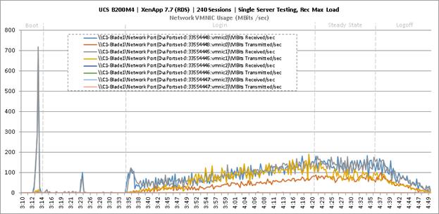
Single-Server Recommended Maximum Workload for VDI Non-Persistent with 195 Users
Figure 55 Single Server Recommended Maximum Workload for VDI Non-Persistent with 195 Users
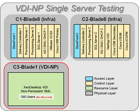
The recommended maximum workload for a B200 M4 blade server with dual E5-2680 v3 processors and 384GB of RAM is 195 Windows 7 32-bit virtual machines with 2 vCPU and 1.7GB RAM. Login VSI and blade performance data follows.
Figure 56 Single Server | XenDesktop 7.7 VDI-NP | VSI Score
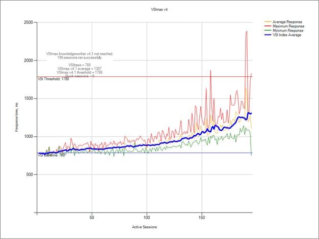
Figure 57 Single Server | XenDesktop 7.7 VDI-NP | VSI Repeatability
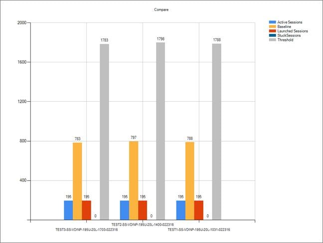
Performance data for the server running the workload follows:
Figure 58 Single Server | XenDesktop 7.7 VDI-NP | Host CPU Utilization
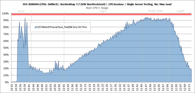
Figure 59 Single Server | XenDesktop 7.7 VDI-NP | Host Memory Utilization
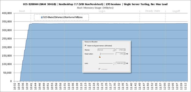
Figure 60 Single Server | XenDesktop 7.7 VDI-NP | Host Network Utilization
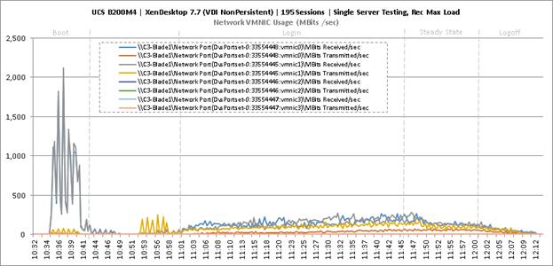
Single-Server Recommended Maximum Workload for VDI Persistent with 195 Users
Figure 61 Single Server Recommended Maximum Workload for VDI Persistent with 195 Users

The recommended maximum workload for a B200 M4 blade server with dual E5-2680 v3 processors and 384GB of RAM is 195 Windows 7 32-bit virtual machines with 2 vCPU and 1.7GB RAM. Login VSI and blade performance data follows.
Figure 62 Single Server | XenDesktop 7.7 VDI-P | VSI Score
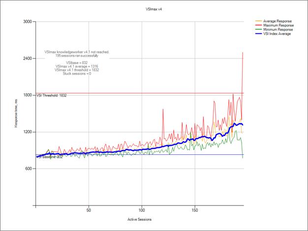
Figure 63 Single Server | XenDesktop 7.7 VDI-P | VSI Repeatability
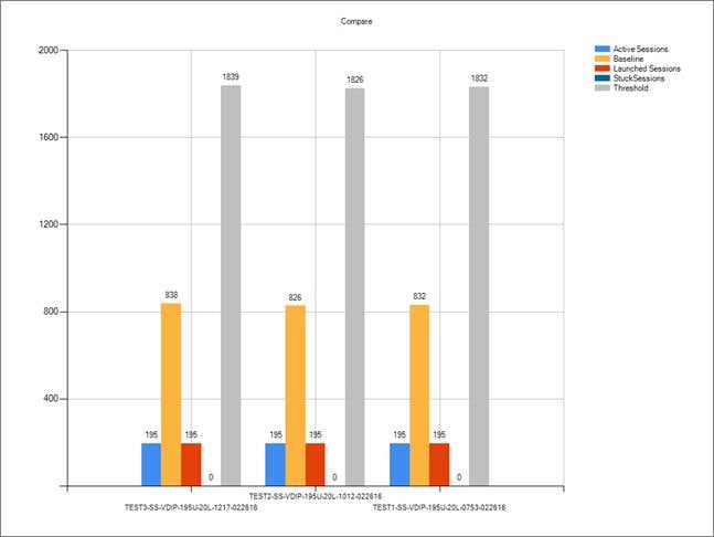
Performance data for the server running the workload follows:
Figure 64 Single Server | XenDesktop 7.7 VDI-P | Host CPU Utilization
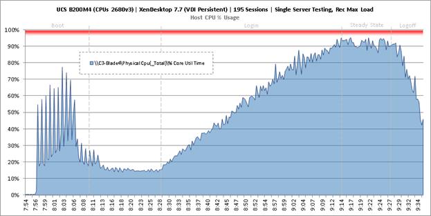
Figure 65 Single Server | XenDesktop 7.7 VDI-P | Host Memory Utilization
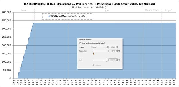
Figure 66 Single Server | XenDesktop 7.7 VDI-P | Host Network Utilization
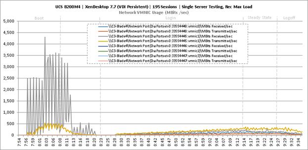
Cluster Workload Testing with 2600 RDS Users
This section shows the key performance metrics that were captured on the Cisco UCS, NetApp storage, and Infrastructure VMs during the non-persistent desktop testing. The cluster testing with comprised of 2600 RDS sessions using 12 workload blades.
Figure 67 RDS Cluster Testing with 2600 Users
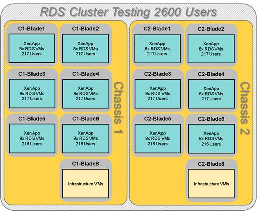
The workload for the test is 2600 RDS users. To achieve the target, sessions were launched against all workload clusters concurrently. As per the Cisco Test Protocol for VDI solutions, all sessions were launched within 48 minutes (using the official Knowledge Worker Workload in VSI Benchmark Mode) and all launched sessions became active within two minutes subsequent to the last logged in session.
The configured system efficiently and effectively delivered the following results.
Figure 68 Cluster | 2600 RDS Users | VSI Score
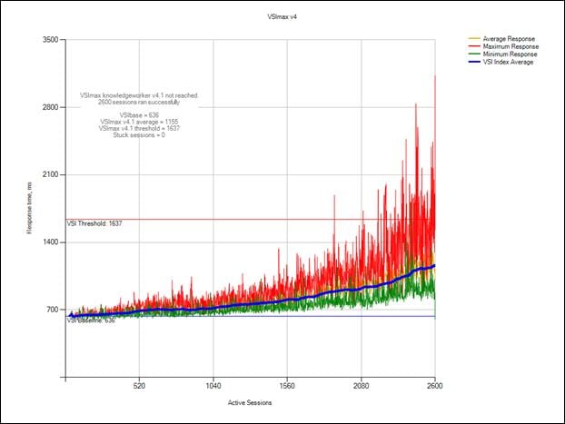
Figure 69 Cluster | 2600 RDS Users | VSI Repeatability
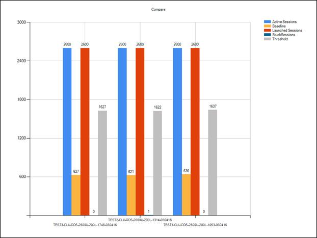
Figure 70 Cluster | 2600 RDS Users | Infrastructure Hosts | Host CPU Utilization
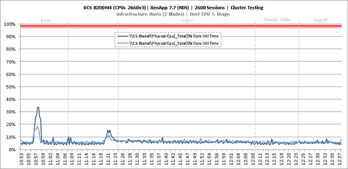
Figure 71 Cluster | 2600 RDS Users | 2 Infrastructure Hosts | Host Memory Utilization
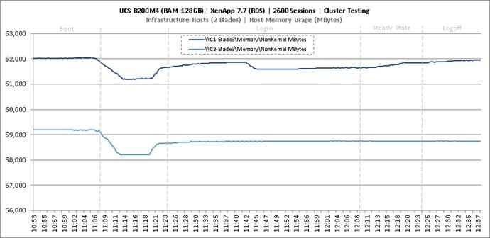
Figure 72 Cluster | 2600 RDS Users | 2 Infrastructure Hosts | Host System Uplink Network Utilization
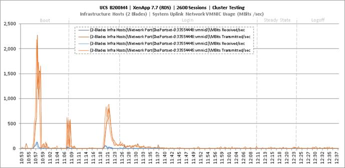
Figure 73 Cluster | 2600 RDS Users | 2 Infrastructure Hosts | Host iSCSI Network Utilization
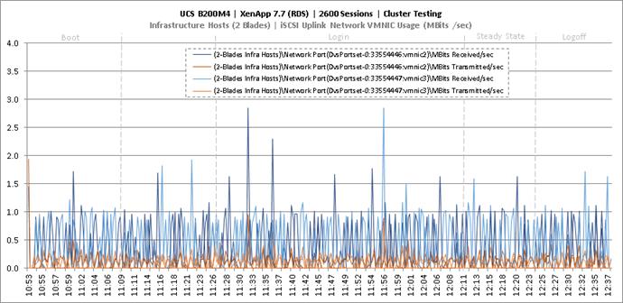
Figure 74 Cluster | 2600 RDS Users | 12 RDS Hosts | Host CPU Utilization
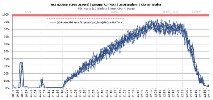
Figure 75 Cluster | 2600 RDS Users | 12 RDS Hosts | Host Memory Utilization
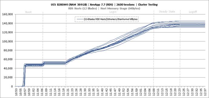
Figure 76 Cluster | 2600 RDS Users | 12 RDS Hosts | Host System Uplink Network Utilization
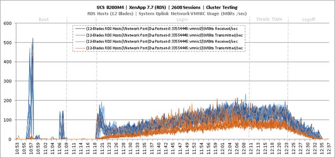
Figure 77 Cluster | 2600 RDS Users | 12 RDS Hosts | Host iSCSI Network Utilization
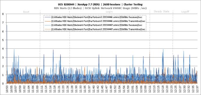
Key NetApp AFF8080EX Performance Metrics During RDS Cluster Workload Testing
This section shows the key performance metrics that were captured on the NetApp storage controller during the RDS cluster workload testing.
Storage Performance Results
§ NetApp Inline Deduplication decreases IOPS during the boot, login, steady-state and logoff phases.
§ Storage can easily handle the 2600 RDS user virtual desktop workload with an average less than 1ms read latency and less than 1ms write latency. According to NetApp SPM sizer, the storage configuration can support up to 5000 RDS users.
During the steady state test the storage experienced very little IOPS due to the Citrix Ram Cache plus overflow feature. The Citrix Ram Cache plus overflow feature offloads the IOPS of the write-cache drives to the compute node (host) but still requires the capacity on the central storage. The following figures 9.X through 9.X are the graphs of the total IOPS and latency experienced on the NetApp AFF8080 during the UCS blade server full-scale tests. Again, the storage latency and Login VSI average response times were way under and well within the acceptable limits. The array managed these IOPS and low latencies using NetApp I/O optimization intelligence with a total of 48 SSDs.
Citrix User Profile Manager (UPM) was used to manage the user’s profiles during the test and the UPM profiles were kept in a CIFS share on NetApp storage. In addition, home directories and folders were redirected to a CIFS share on NetApp storage. Per Citrix’ best practices, it is recommended to place the PVS vDisk on a CIFS share as well; as such, the PVS vDisk resided on a CIFS SMB3 share on NetApp storage.
Figure 78 through Figure 82 depicts the storage volumes for the RDS workload for 2600 users. The graph shows total IOPS and Latency for 2600 RDS user workload during Boot, Login, Steady State, and Logoff periods for the CIFS workload during the LoginVSI test. The RDS workload included the IOPS for UPM user profiles, User Shares, and PVS vDisk. Again, the latency was extremely low and the RDS response time was extremely fast.
Figure 78 Cluster | 2600 RDS Users | AFF8080EX Total Stats | Storage IOPS & Latency
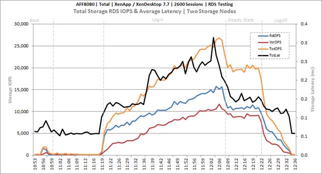
Figure 79 Cluster | 2600 RDS Users | AFF8080EX Infrastructure VMs Volume | Storage IOPS & Latency
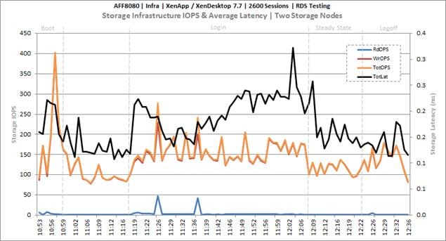
Figure 80 Cluster | 2600 RDS Users | AFF8080EX PVS vDISK CIFS Volume | Storage IOPS & Latency
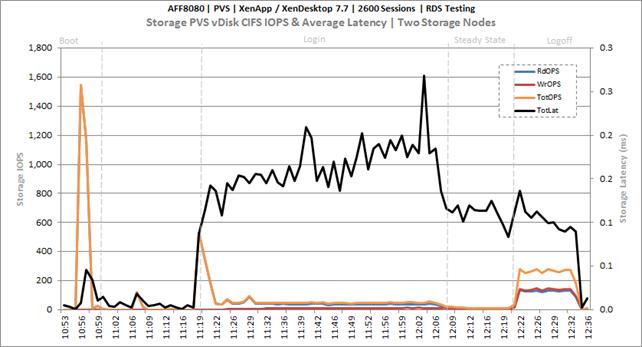
Figure 81 Cluster | 2600 RDS Users | AFF8080EX User Data CIFS Volume | Storage IOPS & Latency
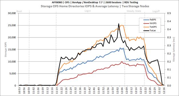
Figure 82 Cluster | 2600 RDS Users | AFF8080EX PVSWC RDS Volumes | Storage IOPS & Latency
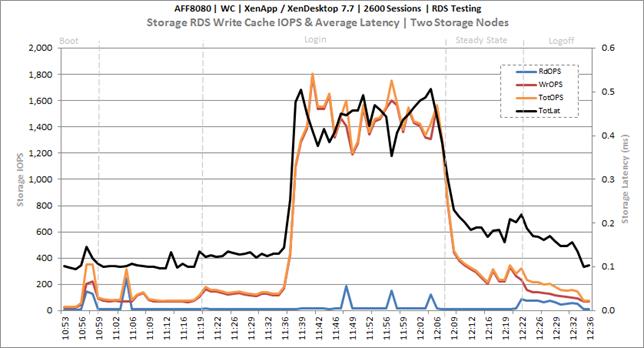
Key Infrastructure VM Server Performance Metrics During RDS Cluster Workload Testing
It is important to verify that key infrastructure servers are performing optimally during the scale test run. The following performance parameters were collected and charted.
The tests validate that the designed infrastructure supports the mixed workload.
Figure 83 Cluster | 2600 RDS Users | Active Directory Domain Controllers | CPU Utilization
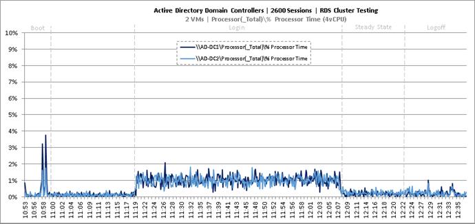
Figure 84 Cluster | 2600 RDS Users | Active Directory Domain Controllers | Memory Utilization
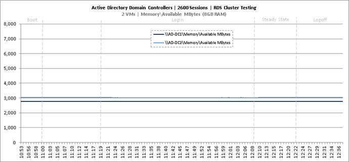
Figure 85 Cluster | 2600 RDS Users | Active Directory Domain Controllers | Network Utilization
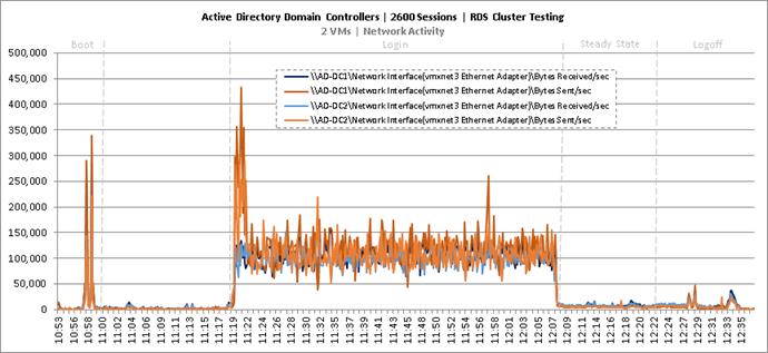
Figure 86 Cluster | 2600 RDS Users | Active Directory Domain Controllers | Disk Queue Lengths
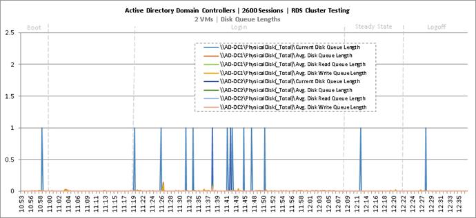
Figure 87 Cluster | 2600 RDS Users | Active Directory Domain Controllers | Disk IO Operations
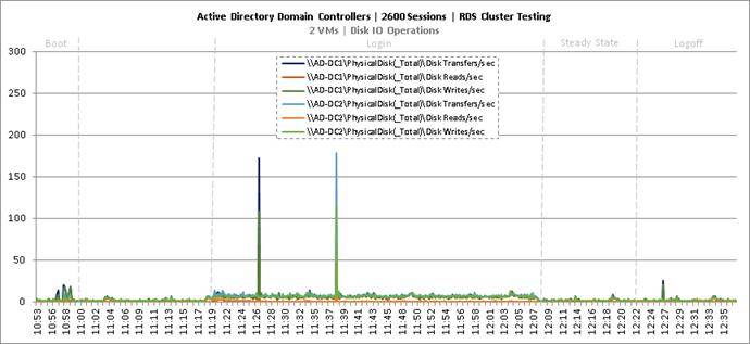
Figure 88 Cluster | 2600 RDS Users | SQL Server | CPU Utilization
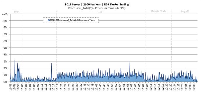
Figure 89 Cluster | 2600 RDS Users | SQL Server | Memory Utilization
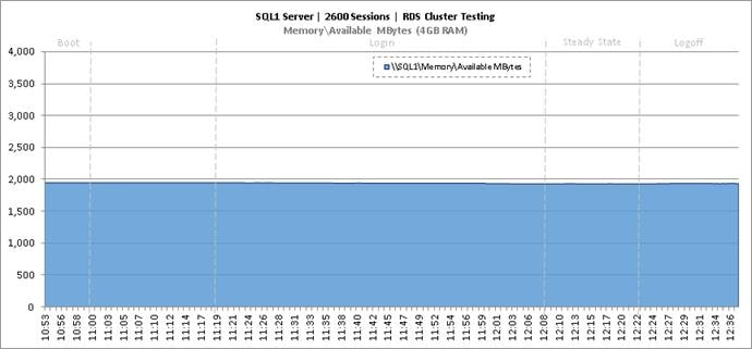
Figure 90 Cluster | 2600 RDS Users | SQL Server | Network Utilization
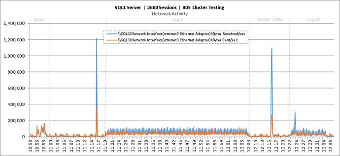
Figure 91 Cluster | 2600 RDS Users | SQL Server | Disk Queue Lengths
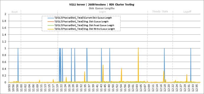
Figure 92 Cluster | 2600 RDS Users | SQL Server | Disk IO Operations
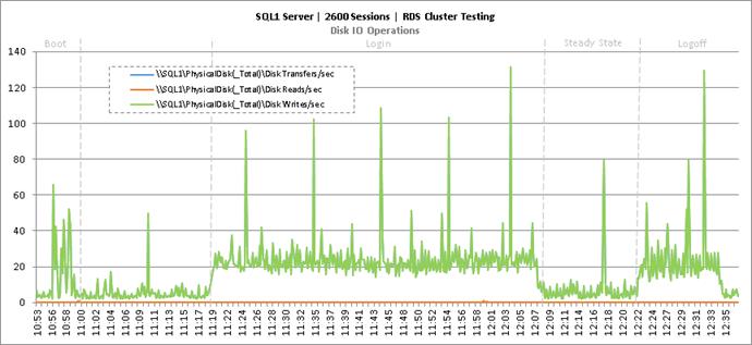
Figure 93 Cluster | 2600 RDS Users | Citrix XenDesktop Desktop Controllers | CPU Utilization
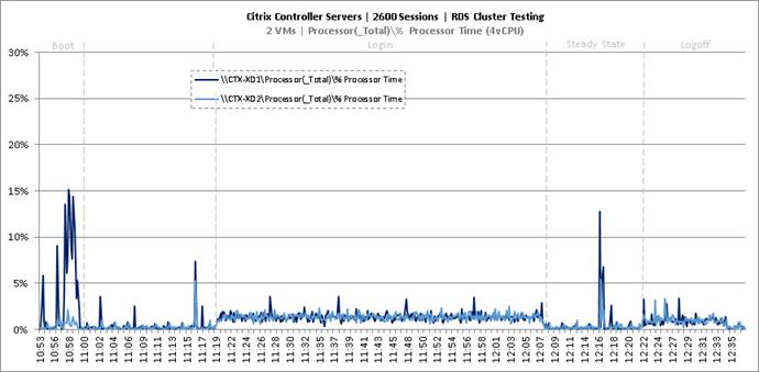
Figure 94 Cluster | 2600 RDS Users | Citrix XenDesktop Desktop Controllers | Memory Utilization
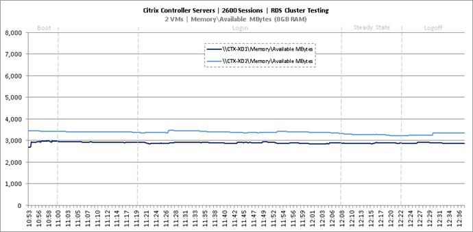
Figure 95 Cluster | 2600 RDS Users | Citrix XenDesktop Desktop Controllers | Network Utilization
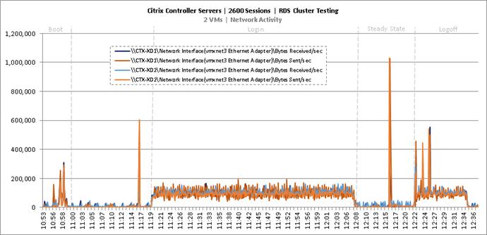
Figure 96 Cluster | 2600 RDS Users | Citrix XenDesktop Desktop Controllers | Disk Queue Lengths
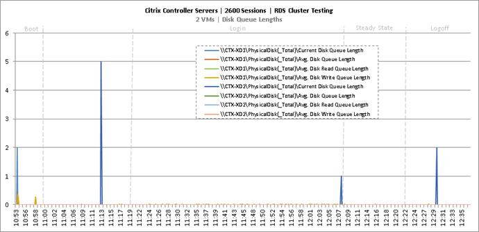
Figure 97 Cluster | 2600 RDS Users | Citrix XenDesktop Desktop Controllers | Disk IO Operations
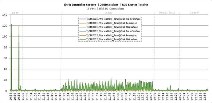
Figure 98 Cluster | 2600 RDS Users | Citrix Provisioning Servers | CPU Utilization
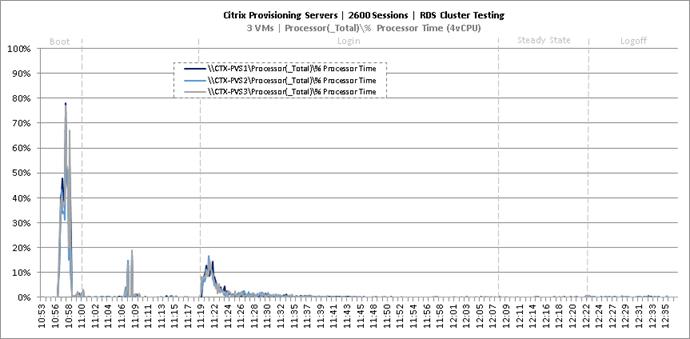
Figure 99 Cluster | 2600 RDS Users | Citrix Provisioning Servers | Memory Utilization
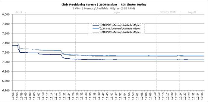
Figure 100 Cluster | 2600 RDS Users | Citrix Provisioning Servers | Network Utilization
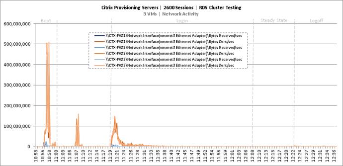
Figure 101 Cluster | 2600 RDS Users | Citrix Provisioning Servers | Disk Queue Lengths
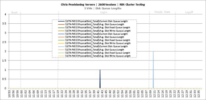
Figure 102 Cluster | 2600 RDS Users | Citrix Provisioning Servers | Disk IO Operations
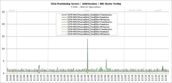
Figure 103 Cluster | 2600 RDS Users | Citrix StoreFront Servers | CPU Utilization
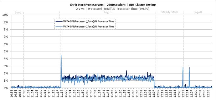
Figure 104 Cluster | 2600 RDS Users | Citrix StoreFront Servers | Memory Utilization
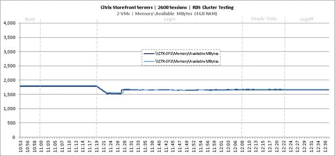
Figure 105 Cluster | 2600 RDS Users | Citrix StoreFront Servers | Network Utilization
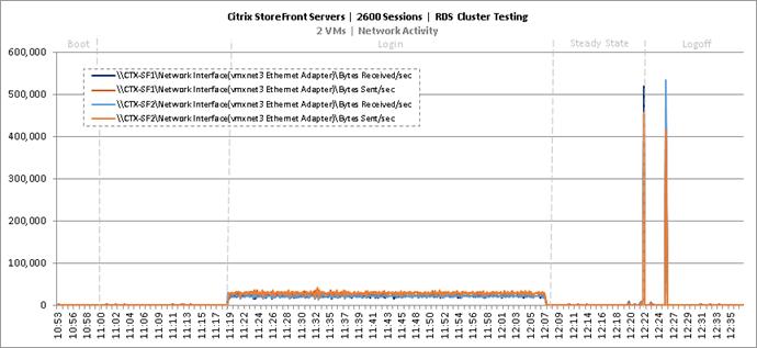
Figure 106 Cluster | 2600 RDS Users | Citrix StoreFront Servers | Disk Queue Lengths
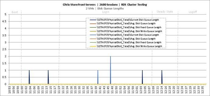
Figure 107 Cluster | 2600 RDS Users | Citrix StoreFront Servers | Disk IO Operations
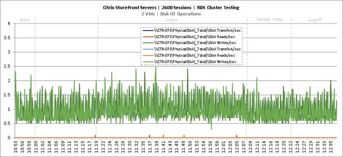
Cluster Workload Testing with 1200 Non-Persistent Desktop Users
This section shows the key performance metrics that were captured on the Cisco UCS, NetApp storage, and Infrastructure VMs during the non-persistent desktop testing. The cluster testing with comprised of 1200 VDI non-persistent desktop sessions using 7 workload blades.
Figure 108 VDI Non-Persistent Cluster Testing with 1200 Users
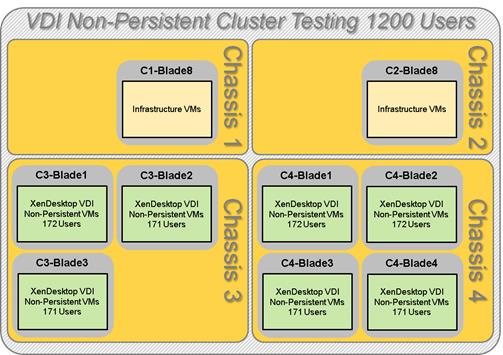
The workload for the test is 1200 non-persistent desktop users. To achieve the target, sessions were launched against all workload clusters concurrently. As per the Cisco Test Protocol for VDI solutions, all sessions were launched within 48 minutes (using the official Knowledge Worker Workload in VSI Benchmark Mode) and all launched sessions became active within two minutes subsequent to the last logged in session.
The configured system efficiently and effectively delivered the following results.
Figure 109 Cluster | 1200 VDI-NP Users | VSI Score
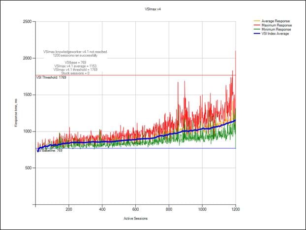
Figure 110 Cluster | 1200 VDI-NP Users | VSI Repeatability
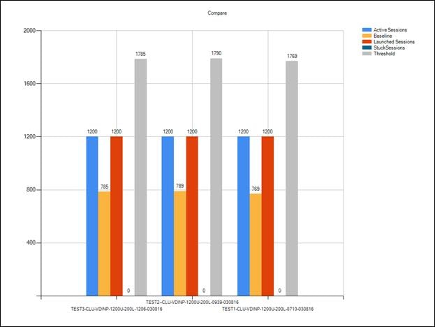
Figure 111 Cluster | 1200 VDI-NP Users | Infrastructure Hosts | Host CPU Utilization
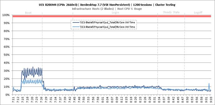
Figure 112 Cluster | 1200 VDI-NP Users | Infrastructure Hosts | Host Memory Utilization
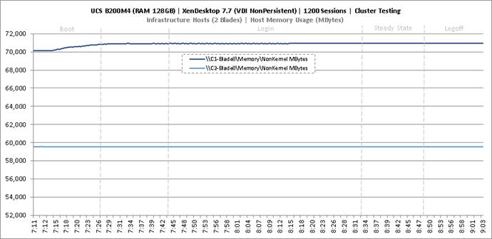
Figure 113 Cluster | 1200 VDI-NP Users | Infrastructure Hosts | Host System Uplink Network Utilization
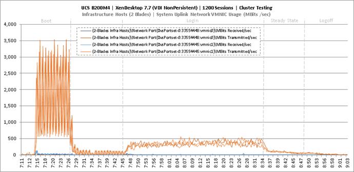
Figure 114 Cluster | 1200 VDI-NP Users | Infrastructure Hosts | Host iSCSI Network Utilization
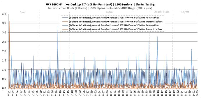
Figure 115 Cluster | 1200 VDI-NP Users | Non-Persistent Hosts | Host CPU Utilization
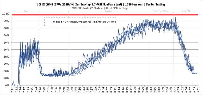
Figure 116 Cluster | 1200 VDI-NP Users | Non-Persistent Hosts | Host Memory Utilization
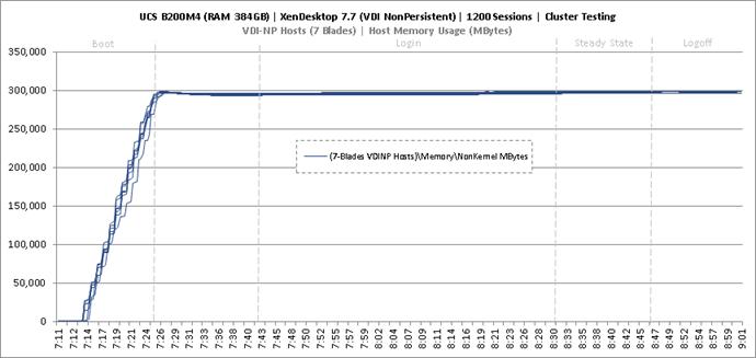
Figure 117 Cluster | 1200 VDI-NP Users | Non-Persistent Hosts | Host System Uplink Network Utilization
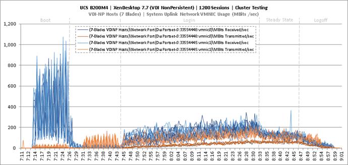
Figure 118 Cluster | 1200 VDI-NP Users | Non-Persistent Hosts | Host iSCSI Network Utilization
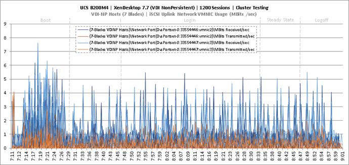
Key NetApp AFF8080EX-A Performance Metrics during VDI Non-Persistent Cluster Workload Testing
This section shows the key performance metrics that were captured on the NetApp storage controller during the VDI non-persistent cluster workload testing.
Storage Performance Results
§ NetApp Inline Deduplication decreases IOPS during the boot, login, steady-state and logoff phases.
§ Storage can easily handle the 1200 Non-Persistent user virtual desktop workload with an average less than 1ms read latency and less than 1ms write latency. According to NetApp SPM sizer, the storage configuration can support up to 5000 users.
During the steady state test the storage experienced very little IOPS due to the Citrix Ram Cache plus overflow feature. The Citrix Ram Cache plus overflow feature offloads the IOPS of the write-cache drives to the compute node (host) but still requires the capacity on the central storage. The following figures 9.X through 9.X are the graphs of the total IOPS and latency experienced on the NetApp AFF8080 during the UCS blade server full-scale tests. Again, the storage latency and Login VSI average response times were way under and well within the acceptable limits. The array managed these IOPS and low latencies using NetApp I/O optimization intelligence with a total of 48 SSDs.
Citrix User Profile Manager (UPM) was used to manage the user’s profiles during the non-persistent test and the UPM profiles were kept in a CIFS share on NetApp storage. In addition, home directories and folders were redirected to a CIFS share on NetApp storage. Per Citrix’ best practices, it is recommended to place the PVS vDisk on a CIFS share as well; as such, the PVS vDisk resided on a CIFS SMB3 share on NetApp storage.
Figure 119 through Figure 123 depicts the volumes for the non-persistent workload for 1200 users. The graph shows total IOPS and Latency for 1200 non-persistent workload users during Boot, Login, Steady State, and Logoff periods during the LoginVSI test. The CIFS workload included the IOPS for UPM user profiles, User Shares, and PVS vDisk. Again, the latency was extremely low and the non-persistent response time was extremely fast.
Figure 119 Cluster | 1200 VDI-NP Users | AFF8080EX Total Stats | Storage IOPS & Latency
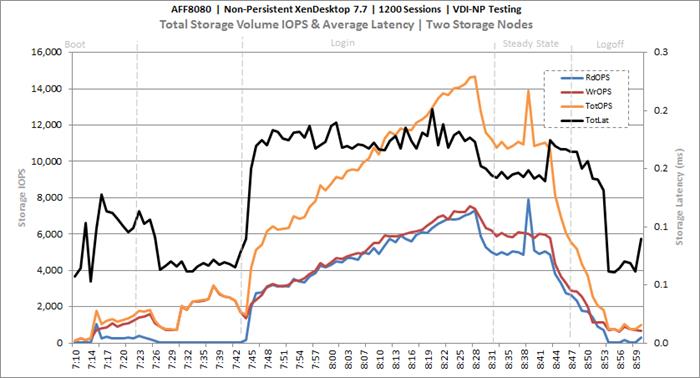
Figure 120 Cluster | 1200 VDI-NP Users | AFF8080EX Infrastructure VMs Volume | Storage IOPS & Latency
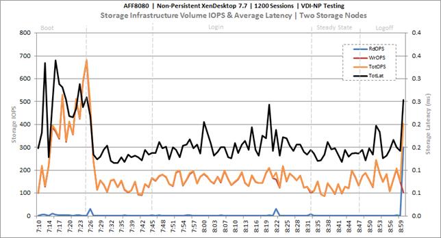
Figure 121 Cluster | 1200 VDI-NP Users | AFF8080EX PVS vDISK CIFS Volume | Storage IOPS & Latency
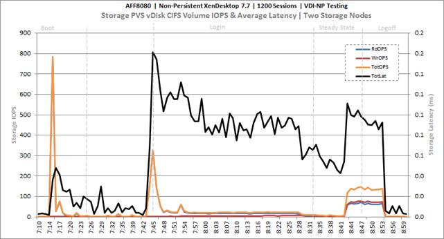
Figure 122 Cluster | 1200 VDI-NP Users | AFF8080EX User Data CIFS Volume | Storage IOPS & Latency
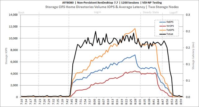
Figure 123 Cluster | 1200 VDI-NP Users | AFF8080EX PVSWC VDI-NP Volumes | Storage IOPS & Latency
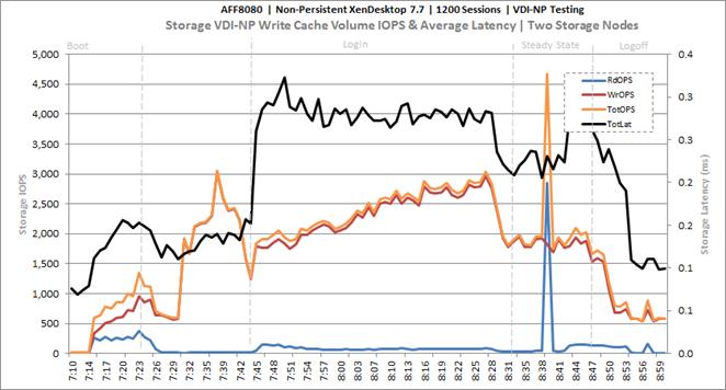
Key Infrastructure VM Server Performance Metrics during VDI Non-Persistent Cluster Workload Testing
It is important to verify that key infrastructure servers are performing optimally during the scale test run. The following performance parameters were collected and charted.
They validate that the designed infrastructure supports the mixed workload.
Figure 124 Cluster | 1200 VDI-NP Users | Active Directory Domain Controllers | CPU Utilization
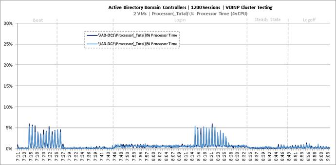
Figure 125 Cluster | 1200 VDI-NP Users | Active Directory Domain Controllers | Memory Utilization
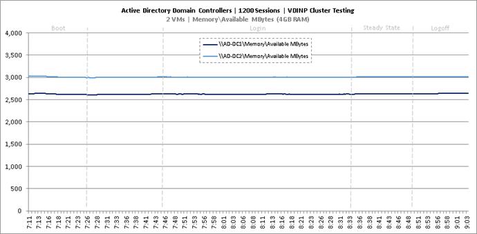
Figure 126 Cluster | 1200 VDI-NP Users | Active Directory Domain Controllers | Network Utilization
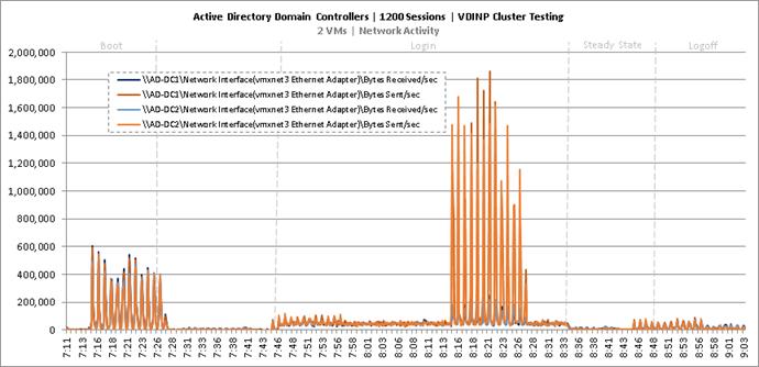
Figure 127 Cluster | 1200 VDI-NP Users | Active Directory Domain Controllers | Disk Queue Lengths
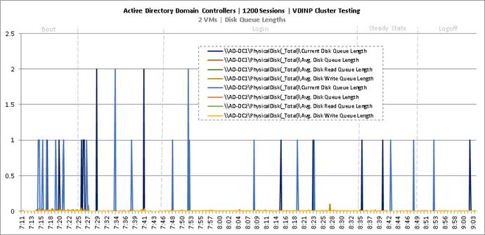
Figure 128 Cluster | 1200 VDI-NP Users | Active Directory Domain Controllers | Disk IO Operations
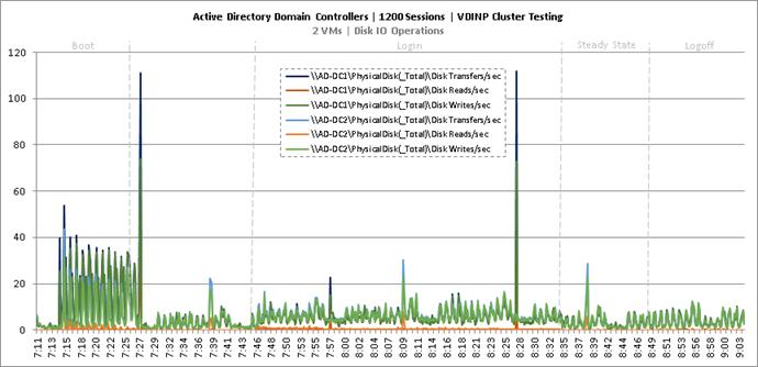
Figure 129 Cluster | 1200 VDI-NP Users | SQL Server | CPU Utilization
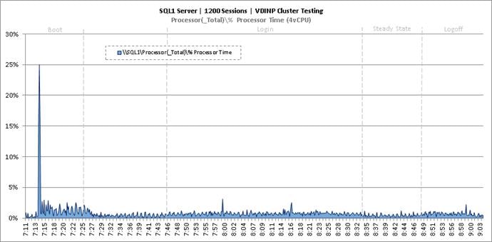
Figure 130 Cluster | 1200 VDI-NP Users | SQL Server | Memory Utilization
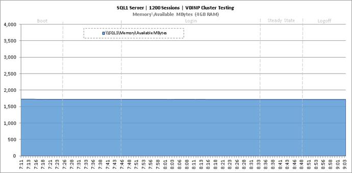
Figure 131 Cluster | 1200 VDI-NP Users | SQL Server | Network Utilization
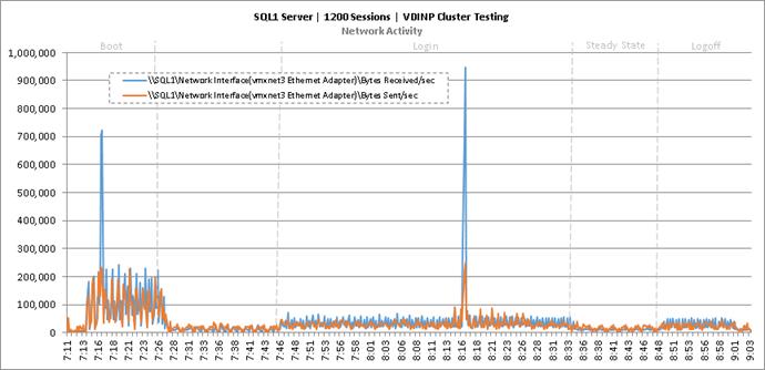
Figure 132 Cluster | 1200 VDI-NP Users | SQL Server | Disk Queue Lengths
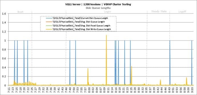
Figure 133 Cluster | 1200 VDI-NP Users | SQL Server | Disk IO Operations
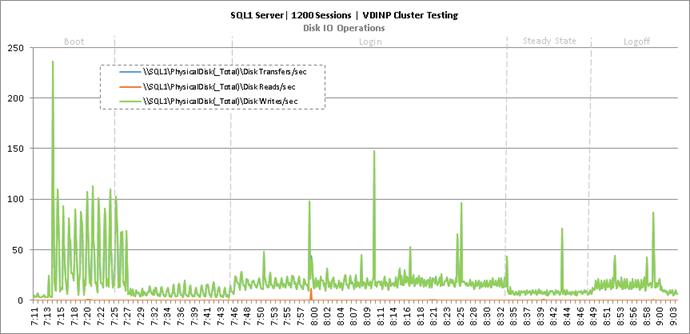
Figure 134 Cluster | 1200 VDI-NP Users | Citrix XenDesktop Desktop Controllers | CPU Utilization
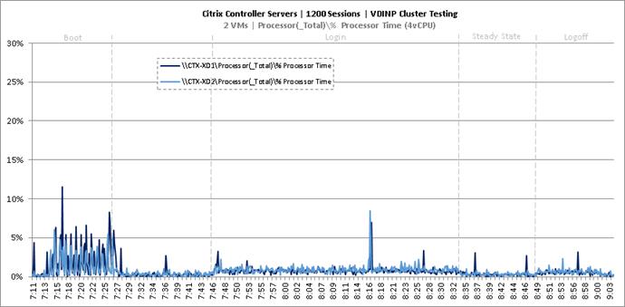
Figure 135 Cluster | 1200 VDI-NP Users | Citrix XenDesktop Desktop Controllers | Memory Utilization
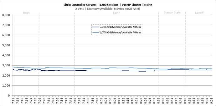
Figure 136 Cluster | 1200 VDI-NP Users | Citrix XenDesktop Desktop Controllers | Network Utilization
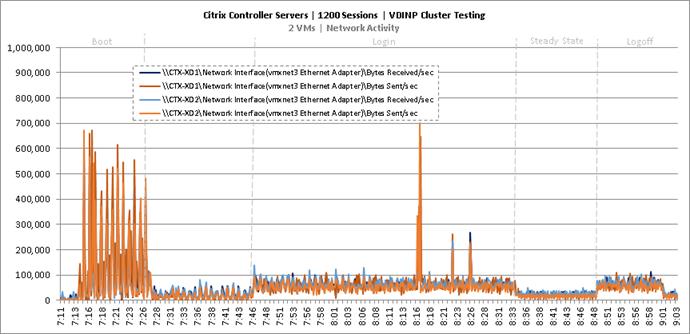
Figure 137 Cluster | 1200 VDI-NP Users | Citrix XenDesktop Desktop Controllers | Disk Queue Lengths
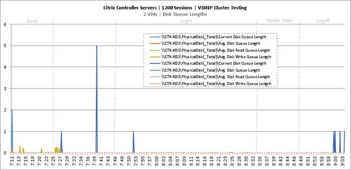
Figure 138 Cluster | 1200 VDI-NP Users | Citrix XenDesktop Desktop Controllers | Disk IO Operations
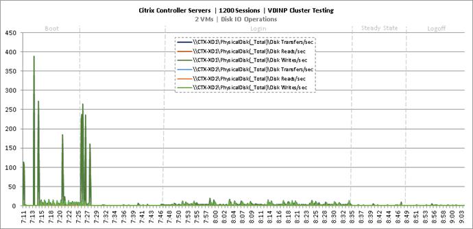
Figure 139 Cluster | 1200 VDI-NP Users | Citrix Provisioning Servers | CPU Utilization
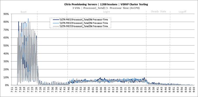
Figure 140 Cluster | 1200 VDI-NP Users | Citrix Provisioning Servers | Memory Utilization
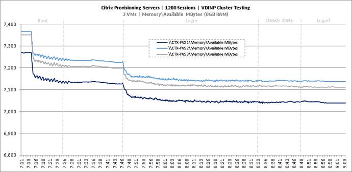
Figure 141 Cluster | 1200 VDI-NP Users | Citrix Provisioning Servers | Network Utilization
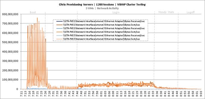
Figure 142 Cluster | 1200 VDI-NP Users | Citrix Provisioning Servers | Disk Queue Lengths
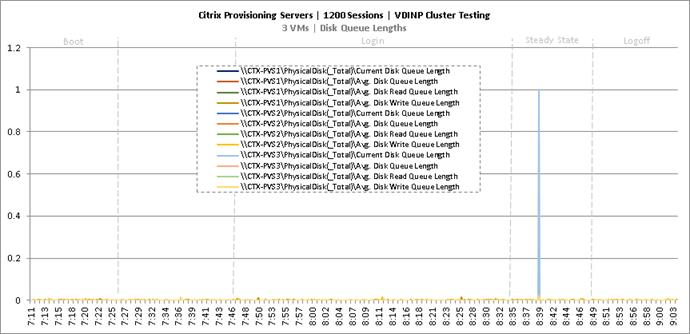
Figure 143 Cluster | 1200 VDI-NP Users | Citrix Provisioning Servers | Disk IO Operations
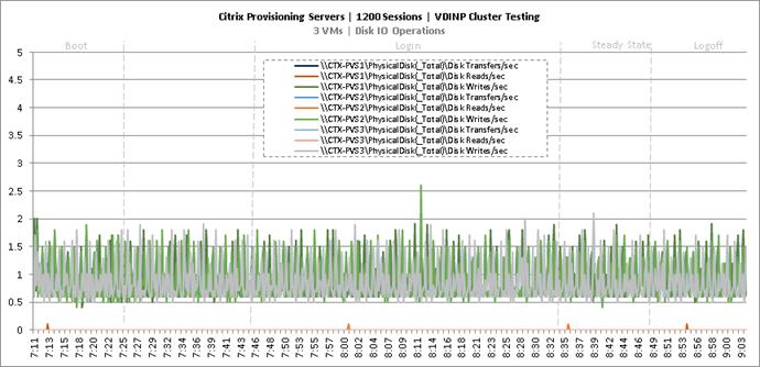
Figure 144 Cluster | 1200 VDI-NP Users | Citrix StoreFront Servers | CPU Utilization
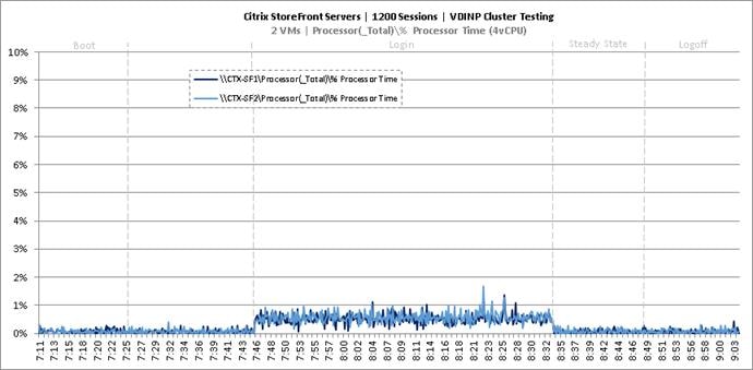
Figure 145 Cluster | 1200 VDI-NP Users | Citrix StoreFront Servers | Memory Utilization
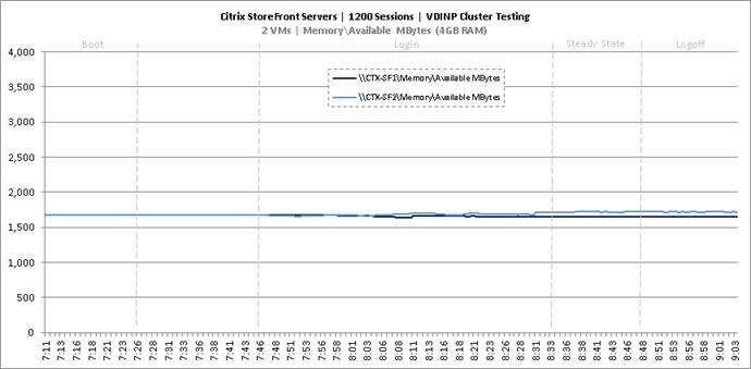
Figure 146 Cluster | 1200 VDI-NP Users | Citrix StoreFront Servers | Network Utilization
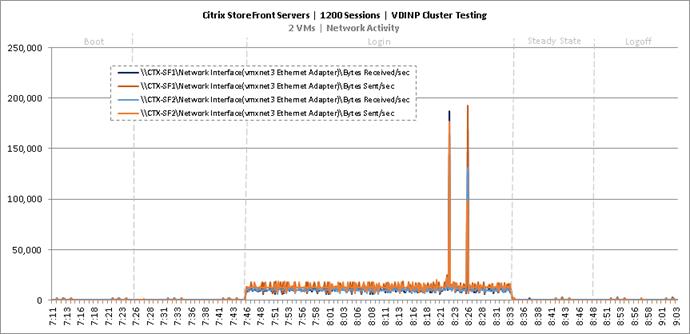
Figure 147 Cluster | 1200 VDI-NP Users | Citrix StoreFront Servers | Disk Queue Lengths
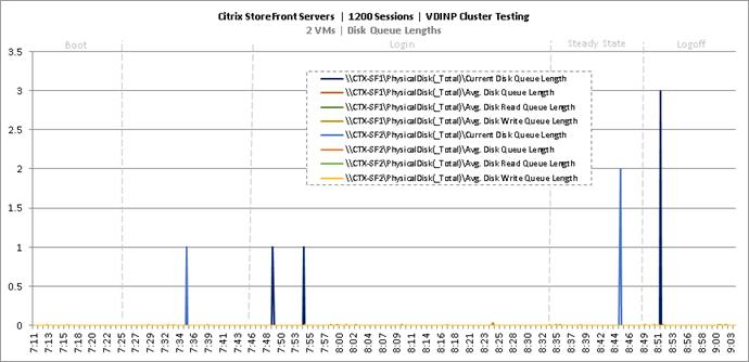
Figure 148 Cluster | 1200 VDI-NP Users | Citrix StoreFront Servers | Disk IO Operations
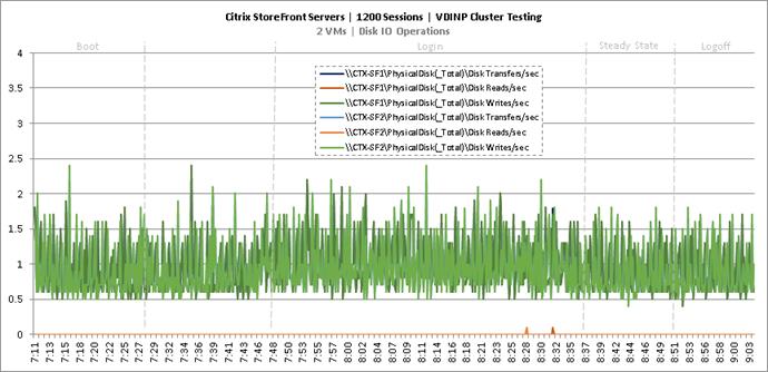
Cluster Workload Testing with 1200 Persistent Desktop Users
This section shows the key performance metrics that were captured on the Cisco UCS, NetApp storage, and Infrastructure VMs during the persistent desktop testing. The cluster testing with comprised of 1200 VDI Persistent desktop sessions using 7 workload blades.
Figure 149 VDI Persistent Cluster Testing with 1200 Users
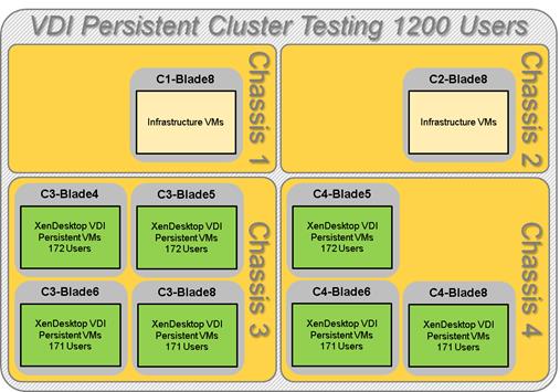
The workload for the test is 1200 persistent desktop users. To achieve the target, sessions were launched against all workload clusters concurrently. As per the Cisco Test Protocol for VDI solutions, all sessions were launched within 48 minutes (using the official Knowledge Worker Workload in VSI Benchmark Mode) and all launched sessions became active within two minutes subsequent to the last logged in session.
The configured system efficiently and effectively delivered the following results.
Figure 150 Cluster | 1200 VDI-P Users | VSI Score
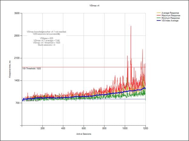
Figure 151 Cluster | 1200 VDI-P Users | VSI Repeatability
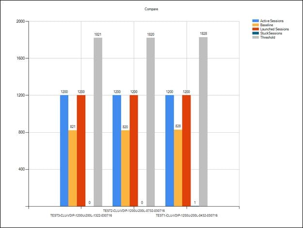
Figure 152 Cluster | 1200 VDI-P Users | Infrastructure Hosts | Host CPU Utilization
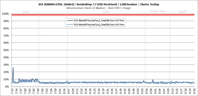
Figure 153 Cluster | 1200 VDI-P Users | Infrastructure Hosts | Host Memory Utilization
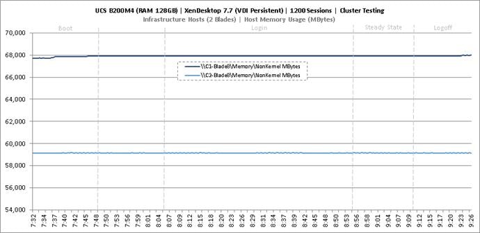
Figure 154 Cluster | 1200 VDI-P Users | Infrastructure Hosts | Host System Uplink Network Utilization
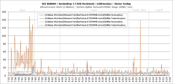
Figure 155 Cluster | 1200 VDI-P Users | Infrastructure Hosts | Host iSCSI Network Utilization
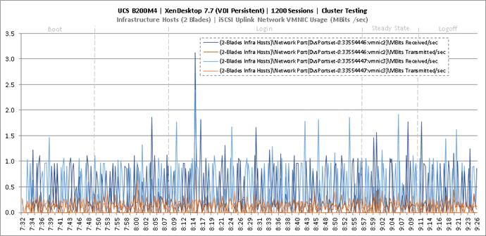
Figure 156 Cluster | 1200 VDI-P Users | Persistent Hosts | Host CPU Utilization
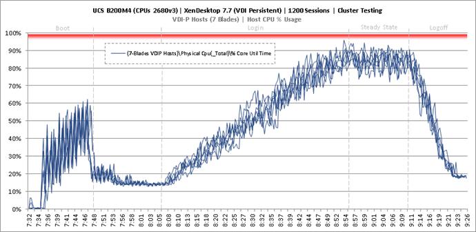
Figure 157 Cluster | 1200 VDI-P Users | Persistent Hosts | Host Memory Utilization
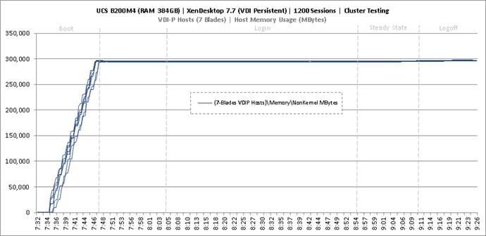
Figure 158 Cluster | 1200 VDI-P Users | Persistent Hosts | Host System Uplink Network Utilization
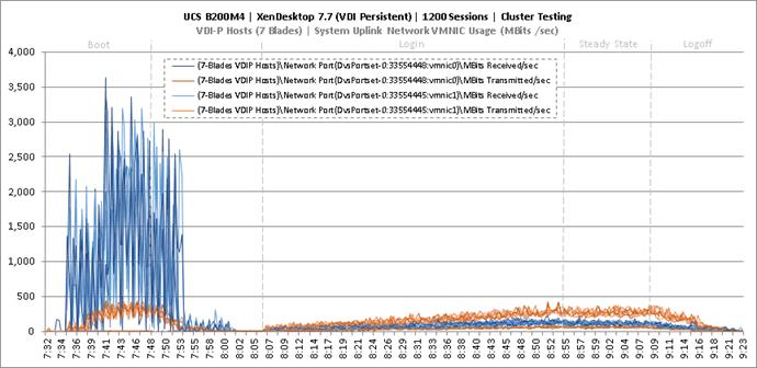
Figure 159 Cluster | 1200 VDI-P Users | Persistent Hosts | Host iSCSI Network Utilization
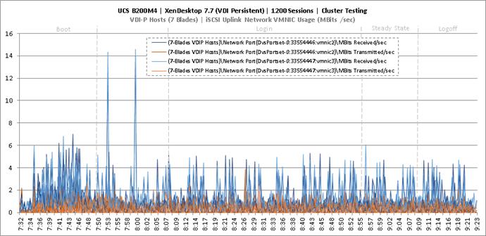
Key NetApp AFF8080EX Performance Metrics during VDI Persistent Cluster Workload Testing
This section shows the key performance metrics that were captured on the NetApp storage controller during the VDI persistent cluster workload testing.
Storage Performance Results
§ NetApp Inline Deduplication decreases IOPS during the boot, login, steady-state and logoff phases.
§ Storage can easily handle the 1200 Non-Persistent user virtual desktop workload with an average less than 1ms read latency and less than 1ms write latency. According to NetApp SPM sizer, the storage configuration can support up to 2500 users.
§ With NetApp clustered Data ONTAP 8.3.2, inline deduplication and compression reduced the size of the persistent desktop data by 92 percent.
Persistent desktops are managed by the Citrix Machine Creation Services (MCS) broker. Citrix MCS does not have the Ram Cache plus overflow feature; therefore, MCS does not have the capability to offload IOPS so the majority of the persistent desktops IOPS were experienced on the storage. In addition, the intial provisioning of the persistent desktops was conducted by NetApp’s Virtual Storage Console (VSC) vCenter plug-in tool. NetApp’s VSC offloads the provisioning from the hypervisor and ustilizing NetApp’s FlexClone feature on the storage. The following figures 9.X through 9.X are the graphs of the total IOPS and latency experienced on the NetApp AFF8080 during the UCS blade server full-scale tests. Again, the storage latency and Login VSI average response times were way under and well within the acceptable limits. The array managed these IOPS and low latencies using NetApp I/O optimization intelligence and a total of 48 SSDs.
Citrix User Profile Manager (UPM) was used to manage the user’s profiles during the test and the UPM profiles were kept in a CIFS share on NetApp storage. In addition, home directories and folders were redirected to a CIFS share on NetApp storage. Per Citrix’ best practices, it is recommended to place the PVS vDisk on a CIFS share as well; as such, the PVS vDisk resided on a CIFS SMB3 share on NetApp storage.
Figure 160 through Figure 163 depicts the Persistent VDI workload for 1200 users. The graph shows tota IOPS and Latency for 1200 Persistent users workload and the user tests during Boot, Login, Steady State, and Logoff periods during the LoginVSI test. The CIFS workload included the IOPS for UPM user profiles, User Shares, and PVS vDisk. Again, the latency was extremely low and the CIFS response time was extremely fast.
Figure 160 Cluster | 1200 VDI-P Users | AFF8080EX Total Stats | Storage IOPS & Latency
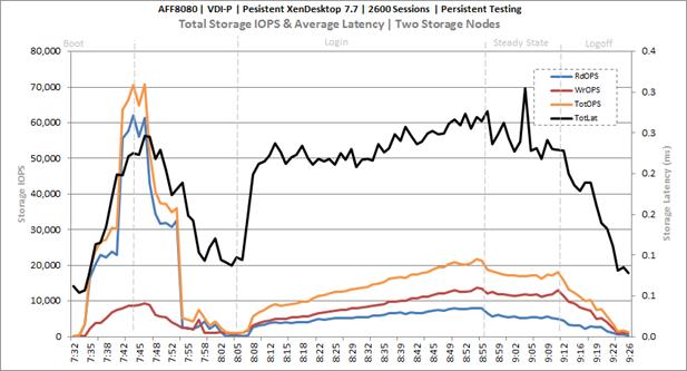
Figure 161 Cluster | 1200 VDI-P Users | AFF8080EX Infrastructure VMs Volume | Storage IOPS & Latency
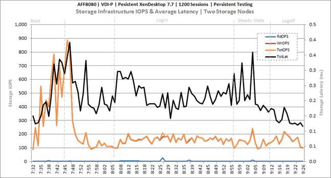
Figure 162 Cluster | 1200 VDI-P Users | AFF8080EX User Data CIFS Volume | Storage IOPS & Latency
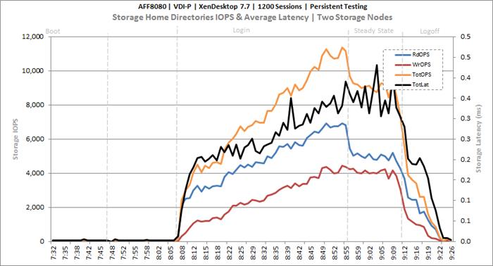
Figure 163 Cluster | 1200 VDI-P Users | AFF8080EX PVSWC VDI-P Volumes | Storage IOPS & Latency
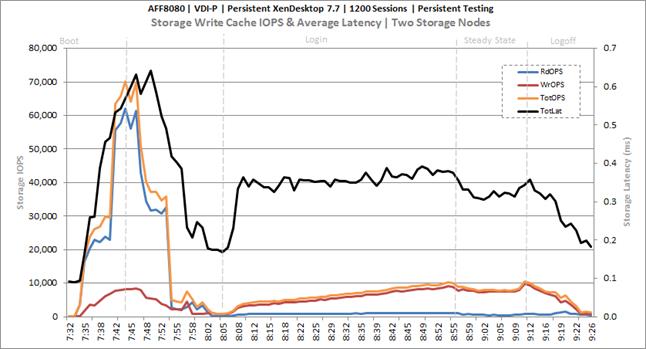
Key Infrastructure VM Server Performance Metrics during VDI Persistent Cluster Testing
It is important to verify that key infrastructure servers are performing optimally during the scale test run. The following performance parameters were collected and charted.
They validate that the designed infrastructure supports the mixed workload.
Figure 164 Cluster | 1200 VDI-P Users | Active Directory Domain Controllers | CPU Utilization
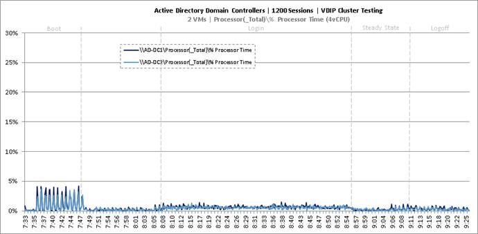
Figure 165 Cluster | 1200 VDI-P Users | Active Directory Domain Controllers | Memory Utilization
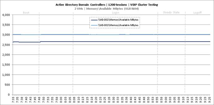
Figure 166 Cluster | 1200 VDI-P Users | Active Directory Domain Controllers | Network Utilization
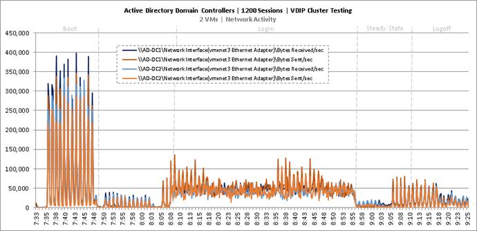
Figure 167 Cluster | 1200 VDI-P Users | Active Directory Domain Controllers | Disk Queue Lengths
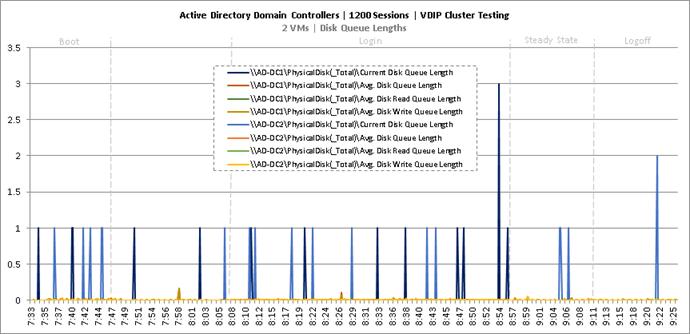
Figure 168 Cluster | 1200 VDI-P Users | Active Directory Domain Controllers | Disk IO Operations
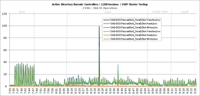
Figure 169 Cluster | 1200 VDI-P Users | SQL Server | CPU Utilization
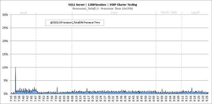
Figure 170 Cluster | 1200 VDI-P Users | SQL Server | Memory Utilization
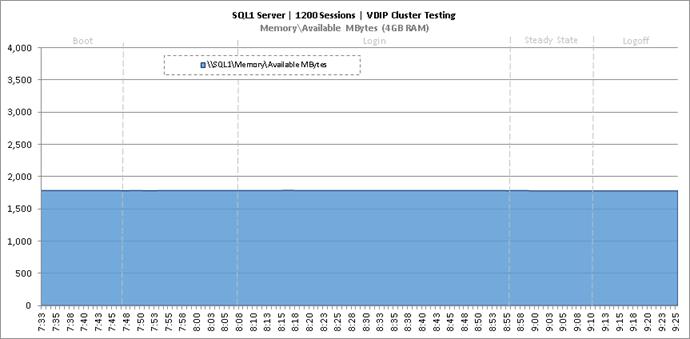
Figure 171 Cluster | 1200 VDI-P Users | SQL Server | Network Utilization
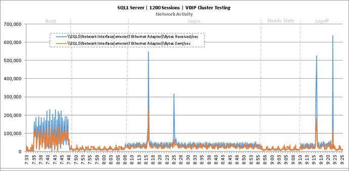
Figure 172 Cluster | 1200 VDI-P Users | SQL Server | Disk Queue Lengths
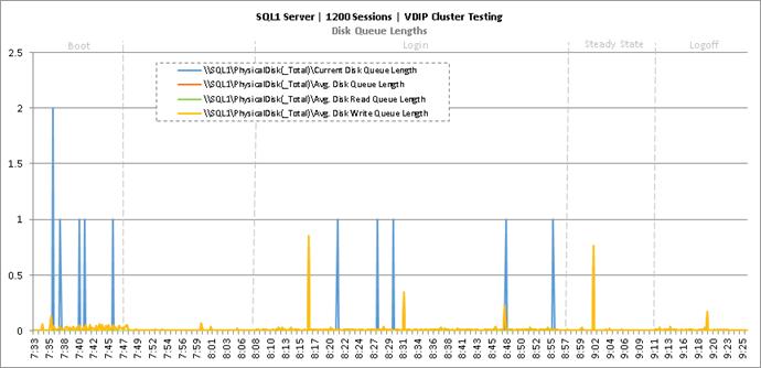
Figure 173 Cluster | 1200 VDI-P Users | SQL Server | Disk IO Operations
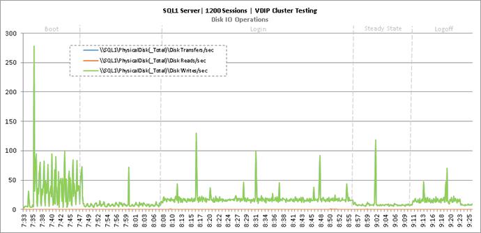
Figure 174 Cluster | 1200 VDI-P Users | Citrix XenDesktop Desktop Controllers | CPU Utilization
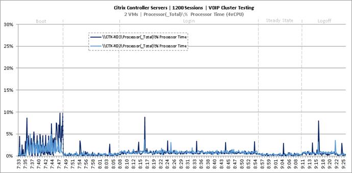
Figure 175 Cluster | 1200 VDI-P Users | Citrix XenDesktop Desktop Controllers | Memory Utilization
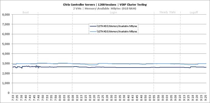
Figure 176 Cluster | 1200 VDI-P Users | Citrix XenDesktop Desktop Controllers | Network Utilization
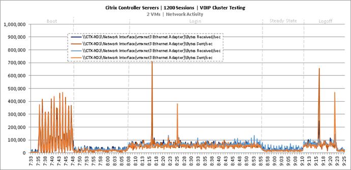
Figure 177 Cluster | 1200 VDI-P Users | Citrix XenDesktop Desktop Controllers | Disk Queue Lengths
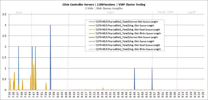
Figure 178 Cluster | 1200 VDI-P Users | Citrix XenDesktop Desktop Controllers | Disk IO Operations
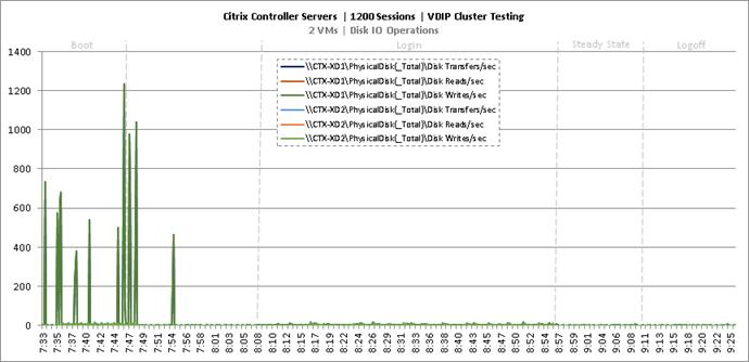
Figure 179 Cluster | 1200 VDI-P Users | Citrix StoreFront Servers | CPU Utilization
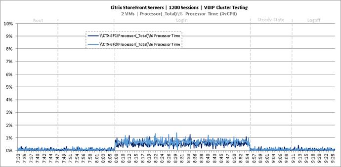
Figure 180 Cluster | 1200 VDI-P Users | Citrix StoreFront Servers | Memory Utilization
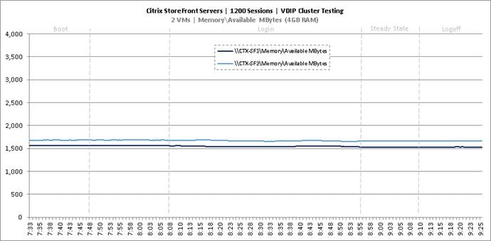
Figure 181 Cluster | 1200 VDI-P Users | Citrix StoreFront Servers | Network Utilization
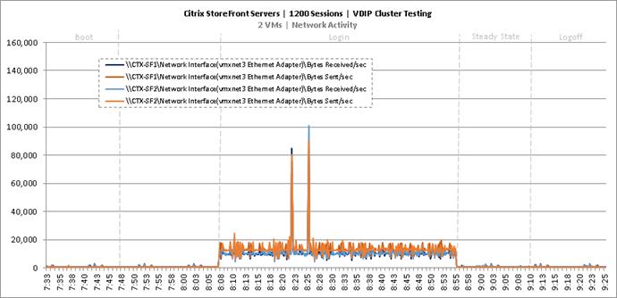
Figure 182 Cluster | 1200 VDI-P Users | Citrix StoreFront Servers | Disk Queue Lengths
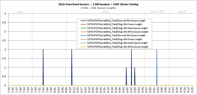
Figure 183 Cluster | 1200 VDI-P Users | Citrix StoreFront Servers | Disk IO Operations
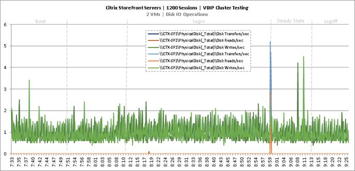
Full Scale Mixed Workload Testing with 5000 Users
This section shows the key performance metrics that were captured on the Cisco UCS, NetApp storage, and Infrastructure VMs during the full-scale testing. The full-scale testing with 5000 users comprised of: 2600 RDS sessions using 12 blades, 1200 VDI Non-Persistent sessions using 7 blades, and 1200 VDI Persistent sessions using 7 blades.
Figure 184 Full Scale Mixed Test with 5000 Users
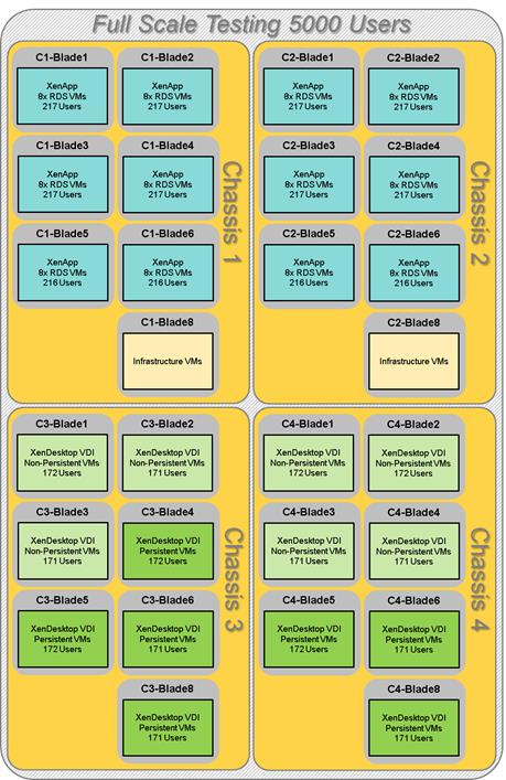
The combined mixed workload for the solution is 5000 users. To achieve the target, sessions were launched against all workload clusters concurrently. As per the Cisco Test Protocol for VDI solutions, all sessions were launched within 48 minutes (using the official Knowledge Worker Workload in VSI Benchmark Mode) and all launched sessions became active within two minutes subsequent to the last logged in session.
The configured system efficiently and effectively delivered the following results.
Figure 185 Full Scale | 5000 Mixed Users | VSI Score
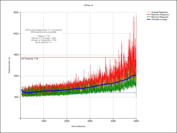
Figure 186 Full Scale | 5000 Mixed Users | VSI Repeatability
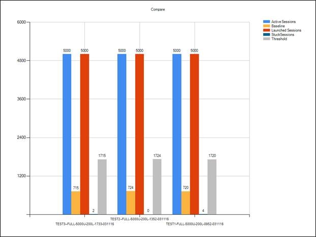
Figure 187 Full Scale | 5000 Mixed Users | Login VSI Management Console Dashboard
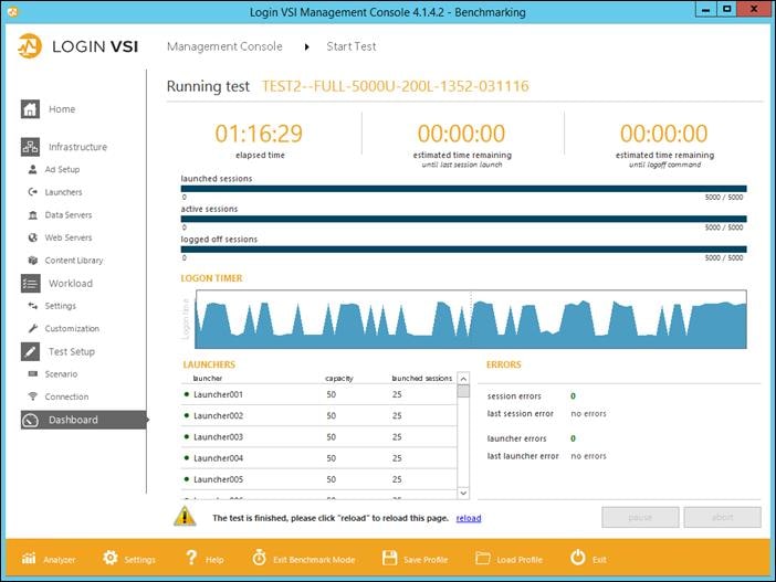
Figure 188 Full Scale | 5000 Mixed Users | Citrix Director | Logon Stats
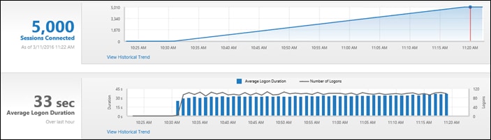
Figure 189 Full Scale | 5000 Mixed Users | Citrix PVS | Balanced Load
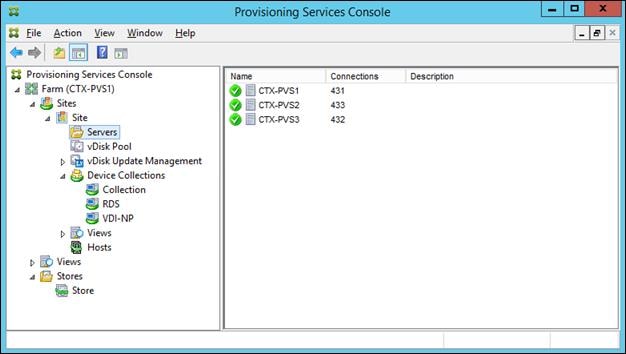
Figure 190 Full Scale | 5000 Mixed Users | Citrix Studio | 5000 Mixed Session Active
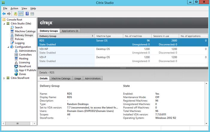
Figure 191 Full Scale | 5000 Mixed Users | Infrastructure Hosts | Host CPU Utilization
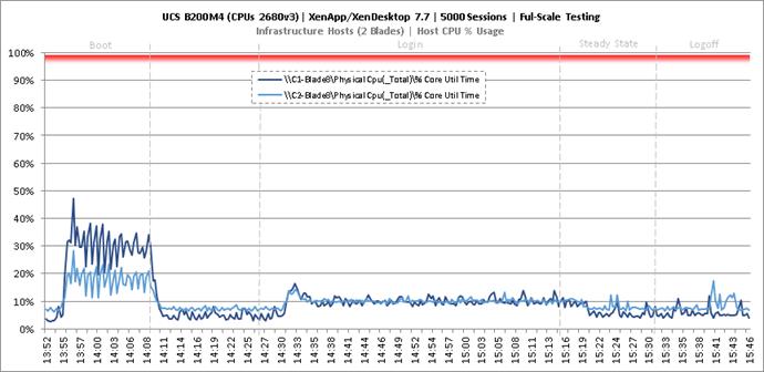
Figure 192 Full Scale | 5000 Mixed Users | Infrastructure Hosts | Host Memory Utilization
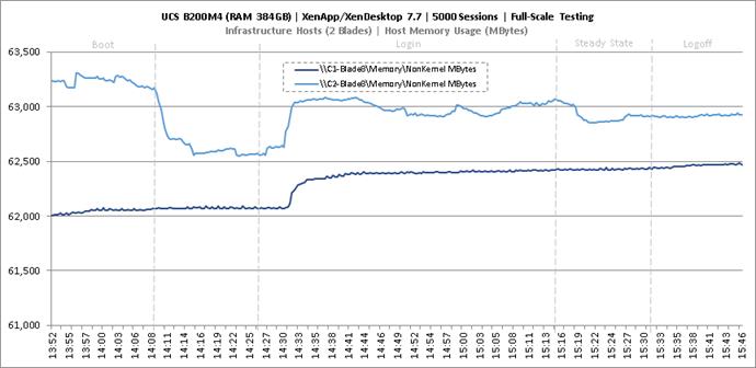
Figure 193 Full Scale | 5000 Mixed Users | Infrastructure Hosts | Host System Uplink Network Utilization
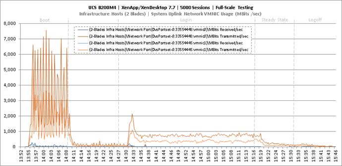
Figure 194 Full Scale | 5000 Mixed Users | Infrastructure Hosts | Host iSCSI Network Utilization
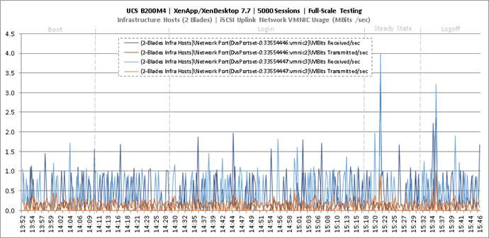
Figure 195 Full Scale | 5000 Mixed Users | RDS Hosts | Host CPU Utilization
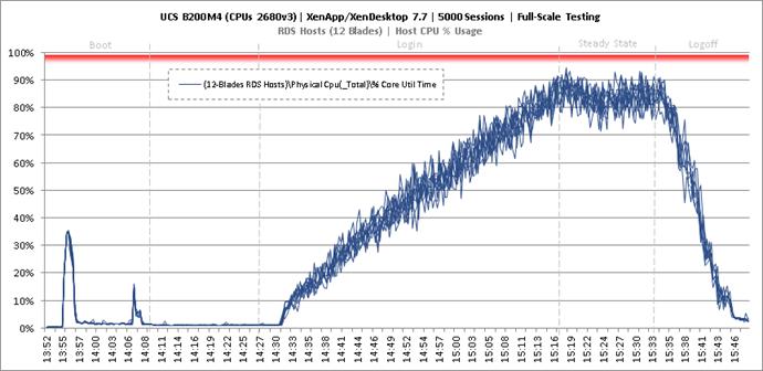
Figure 196 Full Scale | 5000 Mixed Users | RDS Hosts | Host Memory Utilization
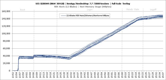
Figure 197 Full Scale | 5000 Mixed Users | RDS Hosts | Host System Uplink Network Utilization
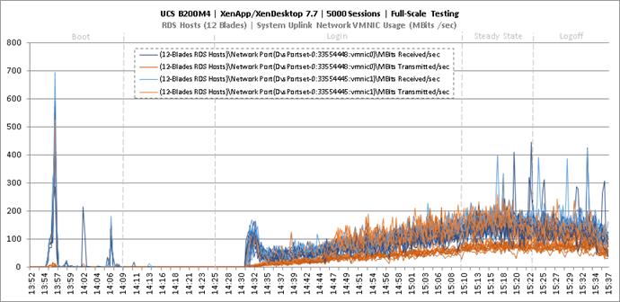
Figure 198 Full Scale | 5000 Mixed Users | RDS Hosts | Host iSCSI Network Utilization
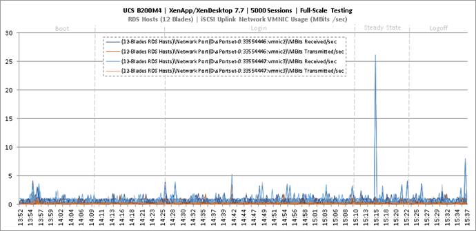
Figure 199 Full Scale | 5000 Mixed Users | Non-Persistent Hosts | Host CPU Utilization
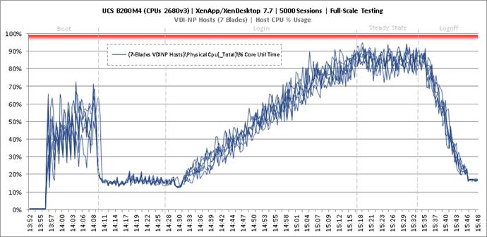
Figure 200 Full Scale | 5000 Mixed Users | Non-Persistent Hosts | Host Memory Utilization
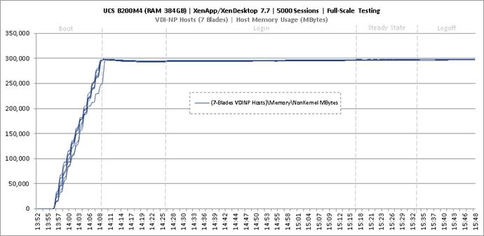
Figure 201 Full Scale | 5000 Mixed Users | Non-Persistent Hosts | Host System Uplink Network Utilization
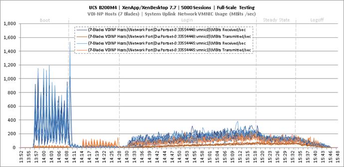
Figure 202 Full Scale | 5000 Mixed Users | Non-Persistent Hosts | Host iSCSI Network Utilization
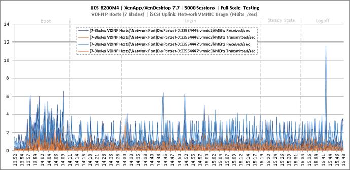
Figure 203 Full Scale | 5000 Mixed Users | Persistent Hosts | Host CPU Utilization
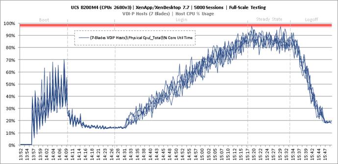
Figure 204 Full Scale | 5000 Mixed Users | Persistent Hosts | Host Memory Utilization
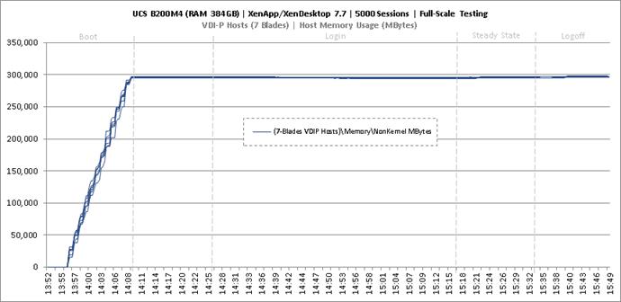
Figure 205 Full Scale | 5000 Mixed Users | Persistent Hosts | Host System Uplink Network Utilization
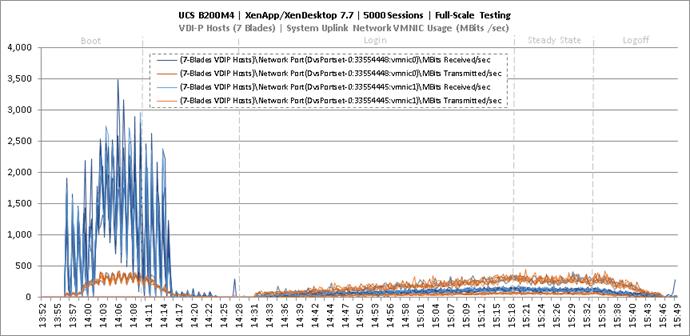
Figure 206 Full Scale | 5000 Mixed Users | Persistent Hosts | Host iSCSI Network Utilization
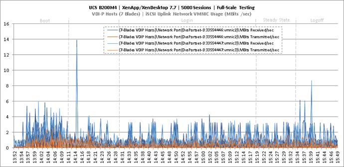
Figure 207 Full Scale | 5000 Mixed Users | VPC11 FI Uplinks to N9ks | VM Boot | UCSPM Network Utilization

Figure 208 Full Scale | 5000 Mixed Users | VPC11 FI Uplinks to N9ks | Login VSI Test | UCSPM Network Utilization
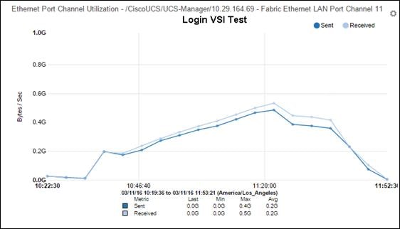
Figure 209 Full Scale | 5000 Mixed Users | VPC12 FI Uplinks to N9ks | VM Boot | UCSPM Network Utilization
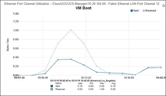
Figure 210 Full Scale | 5000 Mixed Users | VPC11 FI Uplinks to N9ks | Login VSI Test | UCSPM Network Utilization
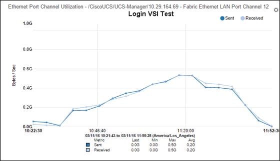
Key NetApp AFF8080EX Performance Metrics during Full Scale Testing
This section shows the key performance metrics that were captured on the NetApp storage controller during the full-scale, mixed workload testing.
Storage Performance Results
§ NetApp Inline Deduplication decreases IOPS during the boot, login, steady-state and logoff phases.
§ Storage can easily handle the 5000-user virtual desktop mixed workload with an average less than 1ms read latency and less than 1ms write latency. According to NetApp SPM sizer, the storage configuration can support up to 5000 users.
§ With NetApp ONTAP 8.3.2, Inline deduplication and Inline Adaptive compression features reduced the size of the persistent desktop data by 92 percent, RDSH desktop data by 64% and reduced the size of the non-persistent desktop data by 37%.
During the steady state test the storage experienced very little IOPS due to the Citrix Ram Cache plus overflow feature. The Citrix Ram Cache plus overflow feature offloads the IOPS of the write-cache drives to the compute node (host) but still requires the capacity on the central storage. The following figures 9.X through 9.X are the graphs of the total IOPS and latency experienced on the NetApp AFF8080 during tCisco UCS blade server and 4 Cisco UCS blade server full-scale 5000 user tests. Again, the storage latency and Login VSI average response times were way under and well within the acceptable limits. The array managed these IOPS and low latencies using NetApp I/O optimization intelligence and a total of 48 SSDs.
The major IOPS experienced by the storage was due to CIFS data. Citrix User Profile Manager (UPM) was used to manage the user’s profiles during the test and the UPM profiles were kept in a CIFS share on NetApp storage. In addition, home directories and folders were redirected to a CIFS share on NetApp storage. Per Citrix’ best practices, it is recommended to place the PVS vDisk on a CIFS share as well; as such, the PVS vDisk resided on a CIFS SMB3 share on NetApp storage.
Figure 211 through Figure 220 depicts the CIFS workload for 5000 users. The graph shows total CIFS IOPS and Latency for 5000 mixed workload users and the 6 Blade 350 user tests during Boot, Login, Steady State, and Logoff periods for the CIFS workload during the LoginVSI test. The CIFS workload included the IOPS for UPM user profiles, User Shares, and PVS vDisk. Again, the latency was extremely low and the CIFS response time was extremely fast.
Figure 211 Full Scale | 5000 Mixed Users | AFF8080EX Total Stats | Storage IOPS & Latency
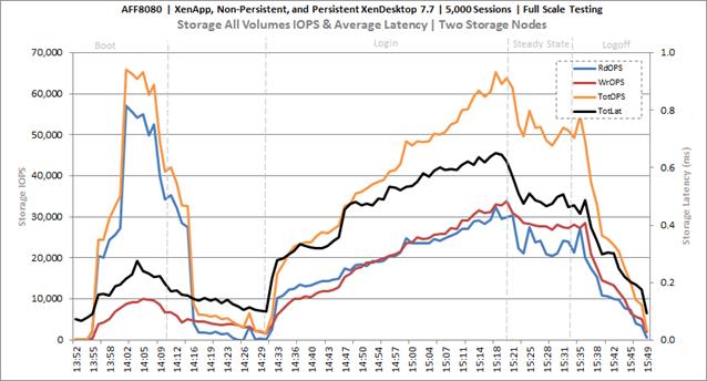
Figure 212 Full Scale | 5000 Mixed Users | AFF8080EX Infra VMs Volume | Storage IOPS & Latency
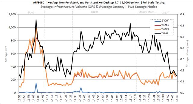
Figure 213 Full Scale | 5000 Mixed Users | AFF8080EX PVS vDISK CIFS Volume | Storage IOPS & Latency
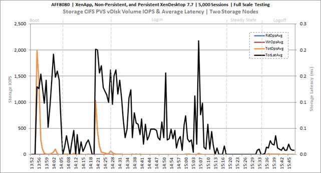
Figure 214 Full Scale | 5000 Mixed Users | AFF8080EX User Data CIFS Volume | Storage IOPS & Latency
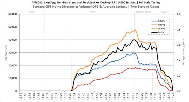
Figure 215 Full Scale | 5000 Mixed Users | AFF8080EX PVSWC RDS Volumes | Storage IOPS & Latency
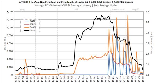
Figure 216 Full Scale | 5000 Mixed Users | AFF8080EX PVSWC RDS Volumes | Storage Efficiency
RDSH Total Savings 64% for inline Deduplication and Inline Compression
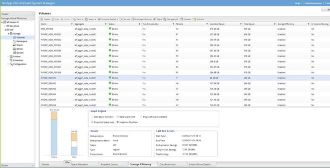
Figure 217 Full Scale | 5000 Mixed Users | AFF8080EX PVSWC VDI-NP Volumes | Storage IOPS & Latency
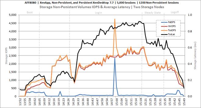
Figure 218 Full Scale | 5000 Mixed Users | AFF8080EX PVSWC VDI-NP Volumes | Storage Efficiency
Non-Persistent Total Savings 37% for inline Deduplication and Inline Compression
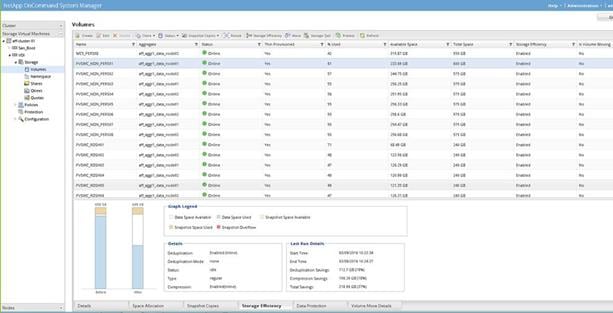
Figure 219 Full Scale | 5000 Mixed Users | AFF8080EX PVSWC VDI-P Volumes | Storage IOPS & Latency
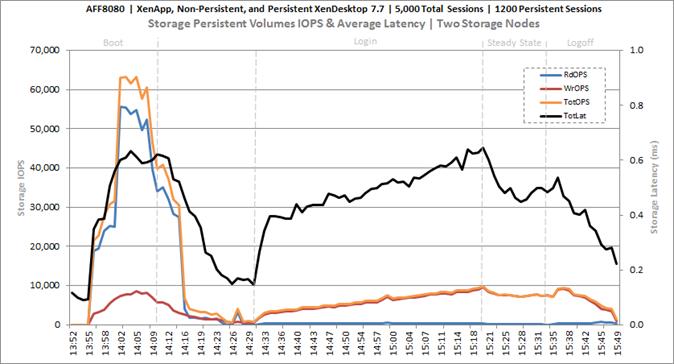
Figure 220 Full Scale | 5000 Mixed Users | AFF8080EX PVSWC VDI-P Volumes | Storage Efficiency
Persistent Total Savings 92% for inline Deduplication and Inline Compression
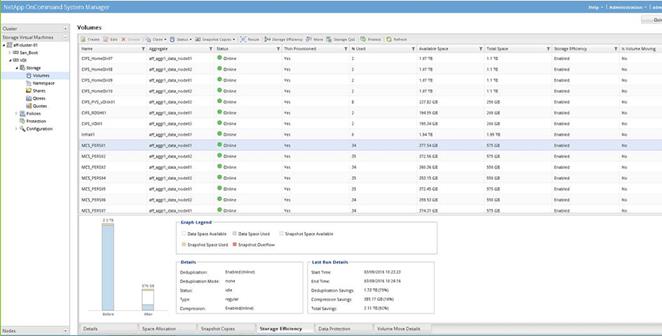
Key Infrastructure VM Server Performance Metrics during Full Scale Testing
It is important to verify that key infrastructure servers are performing optimally during the scale test run. The following performance parameters were collected and charted.
They validate that the designed infrastructure supports the mixed workload.
Figure 221 Full Scale | 5000 Mixed Users | Active Directory Domain Controllers | CPU Utilization
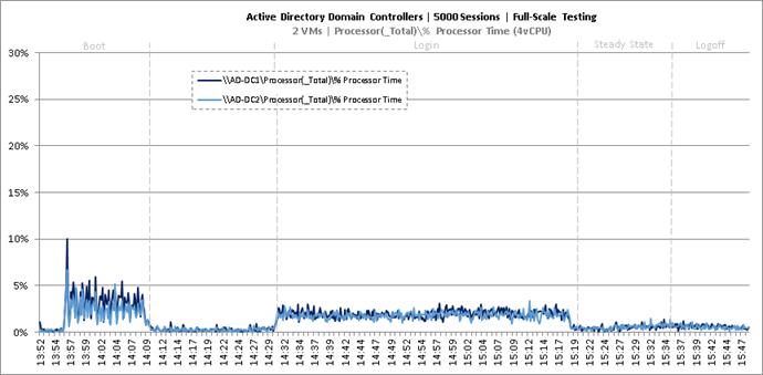
Figure 222 Full Scale | 5000 Mixed Users | Active Directory Domain Controllers | Memory Utilization
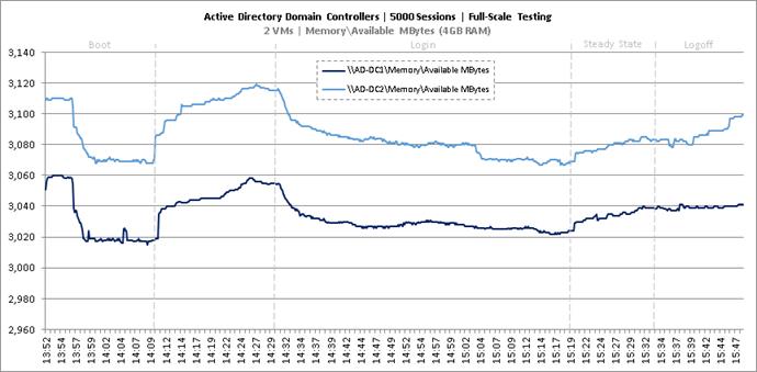
Figure 223 Full Scale | 5000 Mixed Users | Active Directory Domain Controllers | Network Utilization
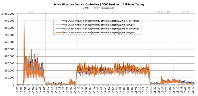
Figure 224 Full Scale | 5000 Mixed Users | Active Directory Domain Controllers | Disk Queue Lengths
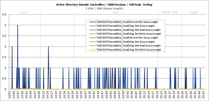
Figure 225 Full Scale | 5000 Mixed Users | Active Directory Domain Controllers | Disk IO Operations
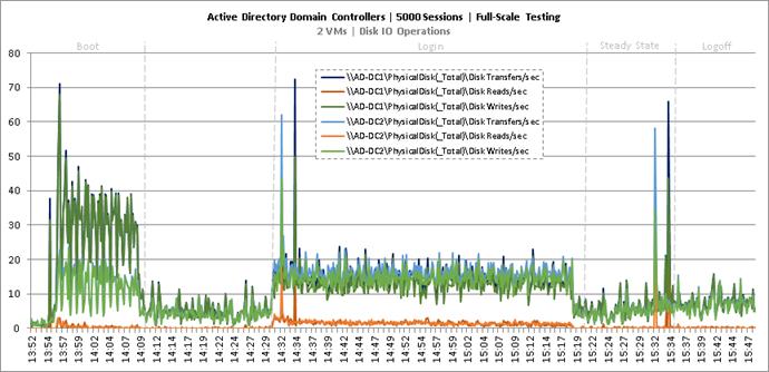
Figure 226 Full Scale | 5000 Mixed Users | SQL Server | CPU Utilization
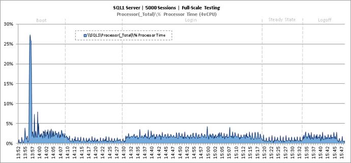
Figure 227 Full Scale | 5000 Mixed Users | SQL Server | Memory Utilization
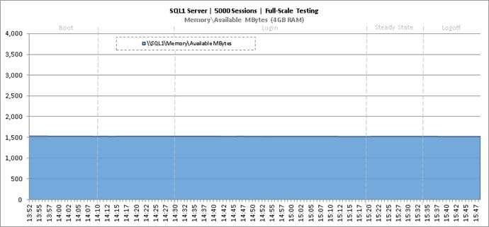
Figure 228 Full Scale | 5000 Mixed Users | SQL Server | Network Utilization
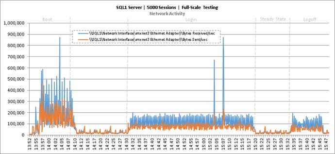
Figure 229 Full Scale | 5000 Mixed Users | SQL Server | Disk Queue Lengths
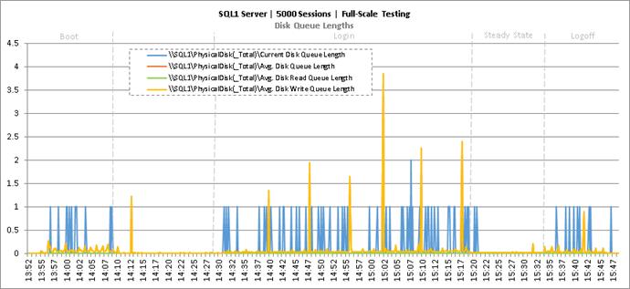
Figure 230 Full Scale | 5000 Mixed Users | SQL Server | Disk IO Operations
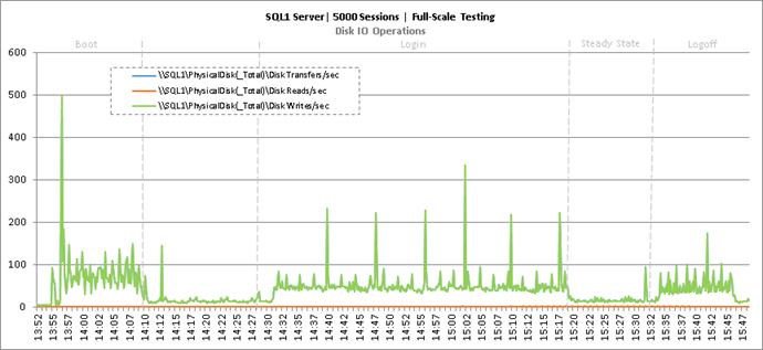
Figure 231 Full Scale | 5000 Mixed Users | Citrix XenDesktop Desktop Controllers | CPU Utilization
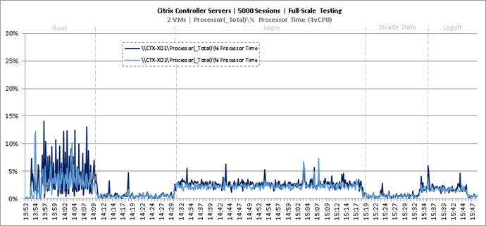
Figure 232 Full Scale | 5000 Mixed Users | Citrix XenDesktop Desktop Controllers | Memory Utilization
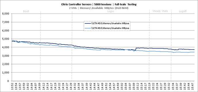
Figure 233 Full Scale | 5000 Mixed Users | Citrix XenDesktop Desktop Controllers | Network Utilization
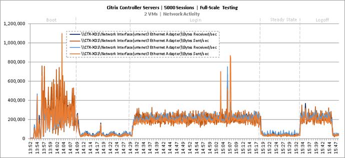
Figure 234 Full Scale | 5000 Mixed Users | Citrix XenDesktop Desktop Controllers | Disk Queue Lengths
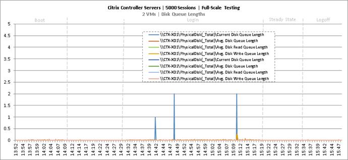
Figure 235 Full Scale | 5000 Mixed Users | Citrix XenDesktop Desktop Controllers | Disk IO Operations
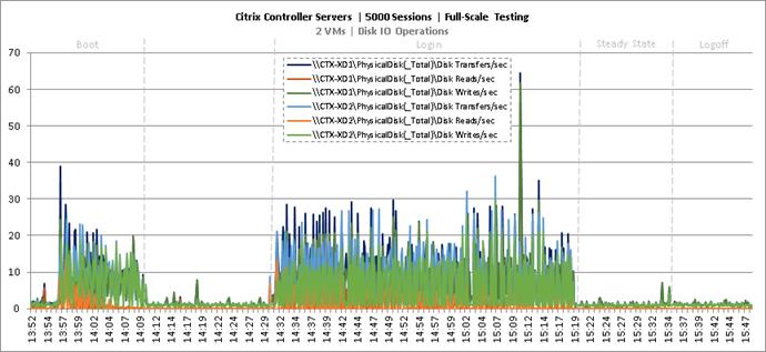
Figure 236 Full Scale | 5000 Mixed Users | Citrix Provisioning Servers | CPU Utilization
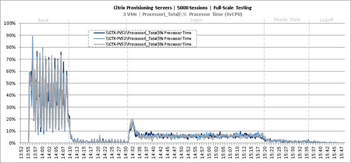
Figure 237 Full Scale | 5000 Mixed Users | Citrix Provisioning Servers | Memory Utilization
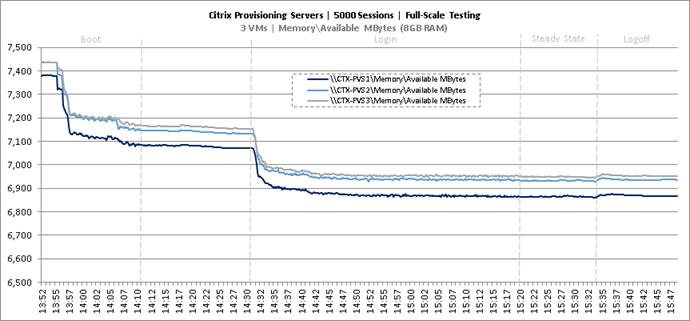
Figure 238 Full Scale | 5000 Mixed Users | Citrix Provisioning Servers | Network Utilization
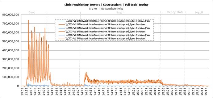
Figure 239 Full Scale | 5000 Mixed Users | Citrix Provisioning Servers | Disk Queue Lengths
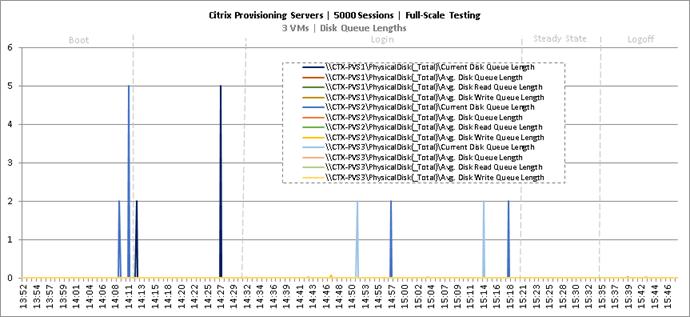
Figure 240 Full Scale | 5000 Mixed Users | Citrix Provisioning Servers | Disk IO Operations
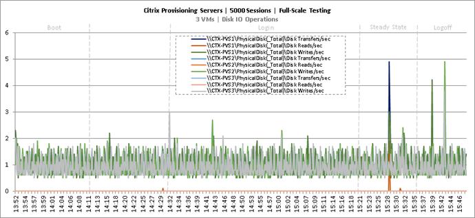
Figure 241 Full Scale | 5000 Mixed Users | Citrix StoreFront Servers | CPU Utilization
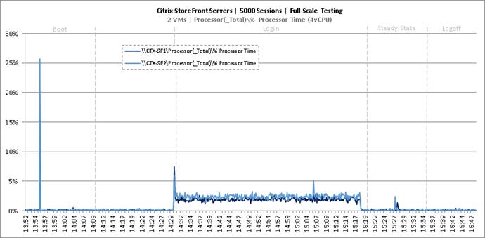
Figure 242 Full Scale | 5000 Mixed Users | Citrix StoreFront Servers | Memory Utilization
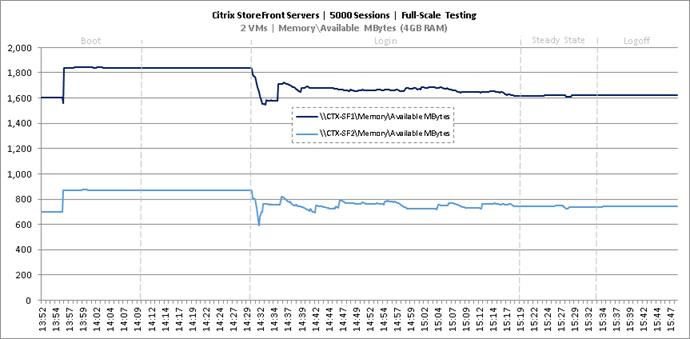
Figure 243 Full Scale | 5000 Mixed Users | Citrix StoreFront Servers | Network Utilization
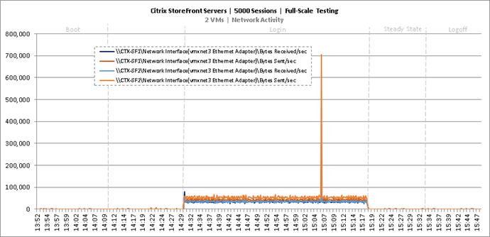
Figure 244 Full Scale | 5000 Mixed Users | Citrix StoreFront Servers | Disk Queue Lengths
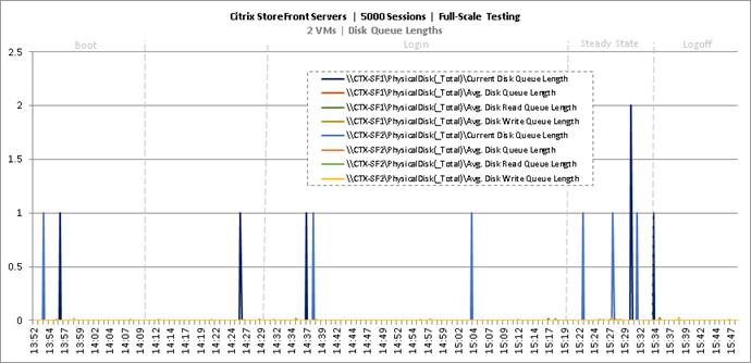
Figure 245 Full Scale | 5000 Mixed Users | Citrix StoreFront Servers | Disk IO Operations
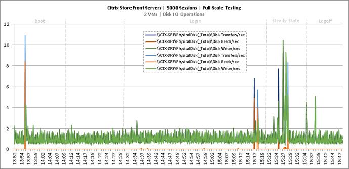
Scalability Considerations and Guidelines
There are many factors to consider when you begin to scale beyond 1000 Users, two chassis 8 mixed workload VDI/HSD host server configuration, which this reference architecture has successfully tested. In this section we give guidance to scale beyond the 1000 user system.
Cisco UCS System Scalability
As our results indicate, we have proven linear scalability in the Cisco UCS Reference Architecture as tested.
§ Cisco UCS Manager Software supports up to 20 Cisco UCS chassis within a single Cisco UCS domain with Cisco UCS 6248UP Fabric Interconnect. A single UCS domain can grow to 160 blades for an enterprise deployment.
§ Cisco UCS Central, the manager of managers, extends UCS domains and vastly increases the reach of the Cisco UCS system. Simplify daily operations by centrally managing and automating routine tasks and expediting problem resolution. Our powerful platform eliminates disparate management environments. Use it to support up to 10,000 Cisco UCS servers (blade, rack, composable, and Mini) and manage multiple Cisco UCS instances or domains across globally-distributed locations.
§ As scale grows, the value of the combined UCS fabric, Nexus physical switches and Nexus virtual switches increases dramatically to define the Quality of Services required to deliver excellent end user experience 100 percent of the time.
§ To accommodate the Cisco Nexus 9000 upstream connectivity in the way we describe in the network configuration section, two Ethernet uplinks are needed to be configured on the Cisco UCS 6248UP Fabric Interconnect.
The backend storage has to be scaled accordingly, based on the IOP considerations as described in the NetApp scaling section. Please refer the NetApp section that follows this one for scalability guidelines.
NetApp FAS Storage Guidelines for Mixed Desktop Virtualization Workloads
Storage sizing has three steps:
§ Gathering solution requirements
§ Estimating storage capacity and performance
§ Obtaining recommendations for the storage configuration
Solution Assessment
Assessment is an important first step. Liquidware Labs Stratusphere FIT and Lakeside VDI Assessment are recommended to collect network, server, and storage requirements. NetApp has contracted with Liquidware Labs to provide free licenses to NetApp employees and channel partners. For information on how to obtain software and licenses, refer to this FAQ. Liquidware Labs also provides a storage template that fits the NetApp system performance modeler. For guidelines on how to use Stratusphere FIT and the NetApp custom report template, refer to TR-3902: Guidelines for Virtual Desktop Storage Profiling.
Virtual desktop sizing depends on the following:
§ The number of the seats
§ The VM workload (applications, VM size, and VM OS)
§ The connection broker (Citrix XenDesktop)
§ The hypervisor type (vSphere, XenServer, or Hyper-V)
§ The provisioning method (NetApp clone, Linked clone, PVS, and MCS)
§ Future storage growth
§ Disaster recovery requirements
§ User home directories
NetApp has developed a sizing tool called the System Performance Modeler (SPM) that simplifies the process of performance sizing for NetApp systems. It has a step-by-step wizard to support varied workload requirements and provides recommendations for meeting your performance needs.
Storage sizing has two factors: capacity and performance. NetApp recommends using the NetApp SPM tool to size the virtual desktop solution. To use this tool, contact NetApp partners and NetApp sales engineers who have the access to SPM. When using the NetApp SPM to size a solution, NetApp recommends separately sizing the VDI workload (including the write cache and personal vDisk if used), and the CIFS profile and home directory workload. When sizing CIFS, NetApp recommends sizing with a heavy user workload. Eighty percent concurrency was assumed in this solution.
Capacity Considerations
Deploying XenDesktop with PVS imposes the following capacity considerations:
§ vDisk. The size of the vDisk depends on the OS and the number of applications installed. It is a best practice to create vDisks larger than necessary in order to leave room for any additional application installations or patches. Each organization should determine the space requirements for its vDisk images.
§ As an example, a 20GB vDisk with a Windows 7 image is used. NetApp deduplication can be used for space savings.
§ Write cache file. NetApp recommends a size range of 4 to 18GB for each user. Write cache size is based on what type of workload and how often the VM is rebooted. In this example, 4GB is used for the write-back cache. Since NFS is thin provisioned by default, only the space currently used by the VM will be consumed on the NetApp storage. If iSCSI or FCP is used, N x 4GB would be consumed as soon as a new virtual machine is created.
§ PvDisk. Normally, 5 to 10GB is allocated, depending on the application and the size of the profile. Use 20 percent of the master image as a starting point. NetApp recommends running deduplication.
§ CIFS home directory. Various factors must be considered for each home directory deployment. The key considerations for architecting and sizing a CIFS home directory solution include the number of users, the number of concurrent users, the space requirement for each user, and the network load. Run deduplication to obtain space savings.
§ Infrastructure. Host XenDesktop, PVS, SQL Server, DNS, and DHCP.
The space calculation formula for a 2000-seat deployment is as follows:
Number of vDisk x 20GB + 2000 x 4GB write cache + 2000 x 10GB PvDisk + 2000 x 5GB user home directory x 70% + 2000 x 1GB vSwap + 500GB infrastructure
Performance Considerations
The collection of performance requirements is a critical step. After using Liquidware Labs Stratusphere FIT and Lakeside VDI Assessment to gather I/O requirements, contact the NetApp account team to obtain recommended software and hardware configurations.
Size, the read/write ratio, and random or sequential reads comprise the I/O considerations. We use 90 percent write and 10 percent read for PVS workload. Storage CPU utilization must also be considered. Table 83 can be used as guidance for your sizing calculations for a PVS workload when using a LoginVSI heavy workload.
Table 83 Typical IOPS without RamCache plus Overflow feature.
|
| Boot IOPS | Login IOPS | Steady IOPS |
| Write Cache (NFS) | 8-10 | 9 | 7.5 |
| vDisk (CIFS SMB 3) | 0.5 | 0 | 0 |
| Infrastructure (NFS) | 2 | 1.5 | 0 |
Scalability of Citrix XenDesktop 7.7 Configuration
XenDesktop environments can scale to large numbers. When implementing Citrix XenDesktop, consider the following in scaling the number of hosted shared and hosted virtual desktops:
§ Types of storage in your environment
§ Types of desktops that will be deployed
§ Data protection requirements
§ For Citrix Provisioning Server pooled desktops, the write cache sizing and placement
These and other various aspects of scalability considerations are described in greater detail in “XenDesktop - Modular Reference Architecture” document and should be a part of any XenDesktop design.
When designing and deploying this CVD environment, best practices were followed including the following:
Citrix recommends using N+1 schema for virtualization host servers to accommodate resiliency. In all Reference Architectures (such as this CVD), this recommendation is applied to all host servers.
§ All Provisioning Server Network Adapters are configured to have a static IP and management.
§ We used the XenDesktop Setup Wizard in PVS. Wizard does an excellent job of creating the desktops automatically and it's possible to run multiple instances of the wizard, provided the deployed desktops are placed in different catalogs and have different naming conventions. To use the PVS XenDesktop Setup Wizard, at a minimum you need to install the Provisioning Server, the XenDesktop Controller, and configure hosts, as well as create VM templates on all datastores where desktops will be deployed.
Network Configuration
The following section provides a detailed procedure for configuring the Cisco Nexus 9000 and 1000V Switches for use in a FlexPod environment.
N9372PX-A Configuration
!Command: show running-config
!Time: Fri Feb 26 16:45:36 2016
version 7.0(3)I1(3b)
switchname DV-Pod-2-N9K-A
class-map type network-qos class-platinum
match qos-group 2
class-map type network-qos class-all-flood
match qos-group 2
class-map type network-qos system_nq_policy
match qos-group 2
class-map type network-qos class-ip-multicast
match qos-group 2
policy-map type network-qos jumbo
class type network-qos class-platinum
mtu 9216
class type network-qos class-default
mtu 9216
vdc DV-Pod-2-N9K-A id 1
limit-resource vlan minimum 16 maximum 4094
limit-resource vrf minimum 2 maximum 4096
limit-resource port-channel minimum 0 maximum 511
limit-resource u4route-mem minimum 248 maximum 248
limit-resource u6route-mem minimum 96 maximum 96
limit-resource m4route-mem minimum 58 maximum 58
limit-resource m6route-mem minimum 8 maximum 8
feature telnet
cfs ipv4 distribute
cfs eth distribute
feature interface-vlan
feature hsrp
feature lacp
feature dhcp
feature vpc
feature lldp
clock protocol none vdc 1
no password strength-check
username admin password 5 $1$tYYajkfc$7P7nLjWYvfTWAlvFDnwJZ. role network-admin
ip domain-lookup
ip access-list NFS_VLAN63
10 permit ip 10.10.63.0 255.255.255.0 any
20 deny ip any any
ip access-list iSCSI-A_64
10 permit ip 10.10.64.0 255.255.255.0 any
20 deny ip any any
ip access-list iSCSI-B_65
10 permit ip 10.10.65.0 255.255.255.0 any
20 deny ip any any
class-map type qos match-any class-platinum
match cos 5
policy-map type qos jumbo
class class-platinum
set qos-group 2
class class-default
set qos-group 0
system qos
service-policy type network-qos jumbo
copp profile strict
snmp-server user admin network-admin auth md5 0xf747567d6cfecf362a9641ac6f3cefc9 priv 0xf747567d6cfecf362a9641ac6f3cefc9 localizedkey
rmon event 1 log trap public description FATAL(1) owner PMON@FATAL
rmon event 2 log trap public description CRITICAL(2) owner PMON@CRITICAL
rmon event 3 log trap public description ERROR(3) owner PMON@ERROR
rmon event 4 log trap public description WARNING(4) owner PMON@WARNING
rmon event 5 log trap public description INFORMATION(5) owner PMON@INFO
ntp server 10.81.254.202
vlan 1-2,60-70,102,164
vlan 60
name In-Band-Mgmt
vlan 61
name Infra-Mgmt
vlan 62
name CIFS
vlan 63
name NFS
vlan 64
name iSCSI-A
vlan 65
name iSCSI-B
vlan 66
name vMotion
vlan 67
name N1KV
vlan 68
name LauncherPXE
vlan 69
name Launcher81
vlan 70
name other-3
vlan 102
name VDI
vlan 164
name Out-Of-Band-Mgmt
spanning-tree port type edge bpduguard default
spanning-tree port type edge bpdufilter default
spanning-tree port type network default
service dhcp
ip dhcp relay
ipv6 dhcp relay
vrf context management
ip route 0.0.0.0/0 10.29.164.1
port-channel load-balance src-dst l4port
vpc domain 10
peer-switch
role priority 10
peer-keepalive destination 10.29.164.66 source 10.29.164.65
delay restore 150
peer-gateway
auto-recovery
interface Vlan1
no ip redirects
no ipv6 redirects
interface Vlan2
description Default native vlan 2
no ip redirects
no ipv6 redirects
interface Vlan60
description Out of Band Management vlan 60
no shutdown
no ip redirects
ip address 10.10.60.2/24
no ipv6 redirects
hsrp version 2
hsrp 60
preempt
priority 110
ip 10.10.60.1
interface Vlan61
description Infrastructure vlan 61
no shutdown
no ip redirects
ip address 10.10.61.2/24
no ipv6 redirects
hsrp version 2
hsrp 61
preempt
ip 10.10.61.1
interface Vlan62
description CIFS vlan 62
no shutdown
no ip redirects
ip address 10.10.62.2/24
no ipv6 redirects
hsrp version 2
hsrp 62
preempt
priority 110
ip 10.10.62.1
interface Vlan63
no shutdown
no ip redirects
ip address 10.10.63.2/24
no ipv6 redirects
hsrp version 2
hsrp 63
preempt
ip 10.10.63.1
interface Vlan64
description iSCSI Fabric A path vlan 64
no shutdown
no ip redirects
ip address 10.10.64.2/24
no ipv6 redirects
hsrp version 2
hsrp 64
preempt
priority 110
ip 10.10.64.1
interface Vlan65
description iSCSI Fabric B path vlan 65
no shutdown
no ip redirects
ip address 10.10.65.2/24
no ipv6 redirects
hsrp version 2
hsrp 65
preempt
ip 10.10.65.1
interface Vlan66
description vMotion network vlan 66
no shutdown
ip address 10.10.66.2/24
hsrp version 2
hsrp 66
preempt
ip 10.10.66.1
interface Vlan67
description Nexus 1000v vlan 67
no shutdown
ip address 10.10.67.2/24
hsrp version 2
hsrp 67
preempt
ip 10.10.67.1
interface Vlan68
description LoginVSI Launchers vlan 68
no shutdown
no ip redirects
ip address 10.10.68.2/24
no ipv6 redirects
hsrp version 2
hsrp 68
preempt
ip 10.10.68.1
interface Vlan69
description LoginVSI Launchers 10.10.81-network vlan 69
no shutdown
no ip redirects
ip address 10.10.81.2/24
no ipv6 redirects
hsrp version 2
hsrp 69
preempt
ip 10.10.81.1
interface Vlan102
description VDI vlan 102
no shutdown
no ip redirects
ip address 10.2.0.2/19
no ipv6 redirects
hsrp version 2
hsrp 102
preempt delay minimum 240
priority 110
timers 1 3
ip 10.2.0.1
ip dhcp relay address 10.10.61.30
interface port-channel10
description VPC-PeerLink
switchport mode trunk
switchport trunk allowed vlan 1-2,60-70,102,164
spanning-tree port type network
vpc peer-link
interface port-channel11
description FI-A_6k_UCS-Uplink
switchport mode trunk
switchport trunk allowed vlan 1-2,60-70,102,164
spanning-tree port type edge trunk
mtu 9216
vpc 11
interface port-channel12
description FI-B_6k_UCS-Uplink
switchport mode trunk
switchport trunk allowed vlan 1-2,60-70,102,164
spanning-tree port type edge trunk
mtu 9216
vpc 12
interface port-channel13
description NetApp_AFF8080_Node_02_CIFS
switchport mode trunk
switchport trunk allowed vlan 62,64-65
spanning-tree port type edge trunk
mtu 9216
vpc 13
interface port-channel14
description NetApp_AFF8080_Node_02_NFS
switchport mode trunk
switchport trunk allowed vlan 63
spanning-tree port type edge trunk
mtu 9216
vpc 14
interface port-channel15
description FI-A_6k_Launchers-Uplink
switchport mode trunk
switchport trunk allowed vlan 1-2,60-70,102,164
spanning-tree port type edge trunk
mtu 9216
vpc 15
interface port-channel16
description FI-B_6k_Launchers-Uplink
switchport mode trunk
switchport trunk allowed vlan 1-2,60-70,102,164
spanning-tree port type edge trunk
mtu 9216
vpc 16
interface port-channel17
description NetApp_AFF8080_Node_01_CIFS
switchport mode trunk
switchport trunk allowed vlan 62,64-65
spanning-tree port type edge trunk
mtu 9216
vpc 17
interface port-channel18
description NetApp_AFF8080_Node_01_NFS
switchport mode trunk
switchport trunk allowed vlan 63
spanning-tree port type edge trunk
mtu 9216
vpc 18
interface Ethernet1/1
description NetApp_AFF8080_Node-02_port_e0e_NFS
switchport mode trunk
switchport trunk allowed vlan 63
mtu 9216
channel-group 14 mode active
interface Ethernet1/2
description NetApp_AFF8080_Node-02_port_e1a_NFS
switchport mode trunk
switchport trunk allowed vlan 63
mtu 9216
channel-group 14 mode active
interface Ethernet1/3
description NetApp_AFF8080_Node-01_port_e0e_NFS
switchport mode trunk
switchport trunk allowed vlan 63
mtu 9216
channel-group 18 mode active
interface Ethernet1/4
description NetApp_AFF8080_Node-01_port_e4a_NFS
switchport mode trunk
switchport trunk allowed vlan 63
mtu 9216
channel-group 18 mode active
interface Ethernet1/5
description NetApp_AFF8080_Node-02_port_e0f_CIFS
switchport mode trunk
switchport trunk allowed vlan 62,64-65
mtu 9216
channel-group 13 mode active
interface Ethernet1/6
description NetApp_AFF8080_Node-02_port_e4a_CIFS
switchport mode trunk
switchport trunk allowed vlan 62,64-65
mtu 9216
channel-group 13 mode active
interface Ethernet1/7
description NetApp_AFF8080_Node-01_port_e0f_CIFS
switchport mode trunk
switchport trunk allowed vlan 62,64-65
mtu 9216
channel-group 17 mode active
interface Ethernet1/8
description NetApp_AFF8080_Node-01_port_e1a_CIFS
switchport mode trunk
switchport trunk allowed vlan 62,64-65
mtu 9216
channel-group 17 mode active
interface Ethernet1/9
interface Ethernet1/10
interface Ethernet1/11
interface Ethernet1/12
interface Ethernet1/13
interface Ethernet1/14
interface Ethernet1/15
interface Ethernet1/16
interface Ethernet1/17
description Uplink_from_FI-A_6k
switchport mode trunk
switchport trunk allowed vlan 1-2,60-70,102,164
mtu 9216
channel-group 11 mode active
interface Ethernet1/18
description Uplink_from_FI-A_6k
switchport mode trunk
switchport trunk allowed vlan 1-2,60-70,102,164
mtu 9216
channel-group 11 mode active
interface Ethernet1/19
description Uplink_from_FI-B_6k
switchport mode trunk
switchport trunk allowed vlan 1-2,60-70,102,164
mtu 9216
channel-group 12 mode active
interface Ethernet1/20
description Uplink_from_FI-B_6k
switchport mode trunk
switchport trunk allowed vlan 1-2,60-70,102,164
mtu 9216
channel-group 12 mode active
interface Ethernet1/21
interface Ethernet1/22
interface Ethernet1/23
interface Ethernet1/24
interface Ethernet1/25
interface Ethernet1/26
interface Ethernet1/27
interface Ethernet1/28
interface Ethernet1/29
interface Ethernet1/30
interface Ethernet1/31
interface Ethernet1/32
interface Ethernet1/33
interface Ethernet1/34
interface Ethernet1/35
interface Ethernet1/36
interface Ethernet1/37
interface Ethernet1/38
interface Ethernet1/39
interface Ethernet1/40
interface Ethernet1/41
interface Ethernet1/42
interface Ethernet1/43
interface Ethernet1/44
interface Ethernet1/45
description Uplink_from_LoginVSI_Launchers_FI-A
switchport mode trunk
switchport trunk allowed vlan 1-2,60-70,102,164
mtu 9216
channel-group 15 mode active
interface Ethernet1/46
description Uplink_from_LoginVSI_Launchers_FI-B
switchport mode trunk
switchport trunk allowed vlan 1-2,60-70,102,164
mtu 9216
channel-group 16 mode active
interface Ethernet1/47
interface Ethernet1/48
description TOR
switchport access vlan 164
interface Ethernet1/49
description VPC Peer Link between 9ks
switchport mode trunk
switchport trunk allowed vlan 1-2,60-70,102,164
channel-group 10 mode active
interface Ethernet1/50
description VPC Peer Link between 9ks
switchport mode trunk
switchport trunk allowed vlan 1-2,60-70,102,164
channel-group 10 mode active
interface Ethernet1/51
interface Ethernet1/52
interface Ethernet1/53
interface Ethernet1/54
interface mgmt0
vrf member management
ip address 10.29.164.65/24
line console
line vty
boot nxos bootflash://sup-1/n9000-dk9.7.0.3.I1.3b.bin
N9372PX-B Configuration
!Command: show running-config
!Time: Fri Feb 26 16:47:01 2016
version 7.0(3)I1(3b)
switchname DV-Pod-2-N9K-B
class-map type network-qos class-platinum
match qos-group 2
class-map type network-qos class-all-flood
match qos-group 2
class-map type network-qos system_nq_policy
match qos-group 2
class-map type network-qos class-ip-multicast
match qos-group 2
policy-map type network-qos jumbo
class type network-qos class-platinum
mtu 9216
class type network-qos class-default
mtu 9216
vdc DV-Pod-2-N9K-B id 1
limit-resource vlan minimum 16 maximum 4094
limit-resource vrf minimum 2 maximum 4096
limit-resource port-channel minimum 0 maximum 511
limit-resource u4route-mem minimum 248 maximum 248
limit-resource u6route-mem minimum 96 maximum 96
limit-resource m4route-mem minimum 58 maximum 58
limit-resource m6route-mem minimum 8 maximum 8
feature telnet
cfs ipv4 distribute
cfs eth distribute
feature interface-vlan
feature hsrp
feature lacp
feature dhcp
feature vpc
feature lldp
clock protocol none vdc 1
no password strength-check
username admin password 5 $1$fp3LrGLC$PF8eML85qkPBgdH/bZAKK/ role network-admin
ip domain-lookup
ip access-list NFS_VLAN63
10 permit ip 10.10.63.0 255.255.255.0 any
20 deny ip any any
ip access-list iSCSI-A_64
10 permit ip 10.10.64.0 255.255.255.0 any
20 deny ip any any
ip access-list iSCSI-B_65
10 permit ip 10.10.65.0 255.255.255.0 any
20 deny ip any any
class-map type qos match-any class-platinum
match cos 5
policy-map type qos jumbo
class class-platinum
set qos-group 2
class class-default
set qos-group 0
system qos
service-policy type network-qos jumbo
copp profile strict
snmp-server user admin network-admin auth md5 0x13ec164cc65d2b9854d70379681039c8 priv 0x13ec164cc65d2b9854d70379681039c8 localizedkey
rmon event 1 log trap public description FATAL(1) owner PMON@FATAL
rmon event 2 log trap public description CRITICAL(2) owner PMON@CRITICAL
rmon event 3 log trap public description ERROR(3) owner PMON@ERROR
rmon event 4 log trap public description WARNING(4) owner PMON@WARNING
rmon event 5 log trap public description INFORMATION(5) owner PMON@INFO
ntp server 10.81.254.202
ntp master 8
vlan 1-2,60-70,102,164
vlan 60
name In-Band-Mgmt
vlan 61
name Infra-Mgmt
vlan 62
name CIFS
vlan 63
name NFS
vlan 64
name iSCSI-A
vlan 65
name iSCSI-B
vlan 66
name vMotion
vlan 67
name N1KV
vlan 68
name LauncherPXE
vlan 69
name Launcher81
vlan 70
name other-3
vlan 102
name VDI
vlan 164
name Out-Of-Band-Mgmt
spanning-tree port type edge bpduguard default
spanning-tree port type edge bpdufilter default
spanning-tree port type network default
service dhcp
ip dhcp relay
ipv6 dhcp relay
vrf context management
ip route 0.0.0.0/0 10.29.164.1
port-channel load-balance src-dst l4port
vpc domain 10
peer-switch
role priority 10
peer-keepalive destination 10.29.164.65 source 10.29.164.66
delay restore 150
peer-gateway
auto-recovery
interface Vlan1
no ip redirects
no ipv6 redirects
interface Vlan2
description Default native vlan 2
no ip redirects
no ipv6 redirects
interface Vlan60
description Out of Band Management vlan 60
no shutdown
no ip redirects
ip address 10.10.60.3/24
no ipv6 redirects
hsrp version 2
hsrp 60
preempt
priority 110
ip 10.10.60.1
interface Vlan61
description Infrastructure vlan 61
no shutdown
no ip redirects
ip address 10.10.61.3/24
no ipv6 redirects
hsrp version 2
hsrp 61
preempt
ip 10.10.61.1
interface Vlan62
description CIFS vlan 62
no shutdown
no ip redirects
ip address 10.10.62.3/24
no ipv6 redirects
hsrp version 2
hsrp 62
preempt
priority 110
ip 10.10.62.1
interface Vlan63
description NFS vlan 63
no shutdown
no ip redirects
ip address 10.10.63.3/24
no ipv6 redirects
hsrp version 2
hsrp 63
preempt
ip 10.10.63.1
interface Vlan64
description iSCSI Fabric A path vlan 64
no shutdown
no ip redirects
ip address 10.10.64.3/24
no ipv6 redirects
hsrp version 2
hsrp 64
preempt
priority 110
ip 10.10.64.1
interface Vlan65
description iSCSI Fabric B path vlan 65
no shutdown
no ip redirects
ip address 10.10.65.3/24
no ipv6 redirects
hsrp version 2
hsrp 65
preempt
ip 10.10.65.1
interface Vlan66
description vMotion network vlan 66
no shutdown
ip address 10.10.66.3/24
hsrp version 2
hsrp 66
preempt
ip 10.10.66.1
interface Vlan67
description Nexus 1000v vlan 67
no shutdown
ip address 10.10.67.3/24
hsrp version 2
hsrp 67
preempt
ip 10.10.67.1
interface Vlan68
description LoginVSI Launchers vlan 68
no shutdown
no ip redirects
ip address 10.10.68.3/24
no ipv6 redirects
hsrp version 2
hsrp 68
preempt
ip 10.10.68.1
interface Vlan69
description LoginVSI Launchers 10.10.81-network vlan 69
no shutdown
no ip redirects
ip address 10.10.81.3/24
no ipv6 redirects
hsrp version 2
hsrp 69
preempt
ip 10.10.81.1
interface Vlan102
description VDI vlan 102
no shutdown
no ip redirects
ip address 10.2.0.3/19
no ipv6 redirects
hsrp version 2
hsrp 102
preempt delay minimum 240
priority 110
timers 1 3
ip 10.2.0.1
ip dhcp relay address 10.10.61.30
interface port-channel10
description VPC-PeerLink
switchport mode trunk
switchport trunk allowed vlan 1-2,60-70,102,164
spanning-tree port type network
vpc peer-link
interface port-channel11
description FI-A_6k_UCS-Uplink
switchport mode trunk
switchport trunk allowed vlan 1-2,60-70,102,164
spanning-tree port type edge trunk
mtu 9216
vpc 11
interface port-channel12
description FI-B_6k_UCS-Uplink
switchport mode trunk
switchport trunk allowed vlan 1-2,60-70,102,164
spanning-tree port type edge trunk
mtu 9216
vpc 12
interface port-channel13
description NetApp_AFF8080_Node_02_CIFS
switchport mode trunk
switchport trunk allowed vlan 62,64-65
spanning-tree port type edge trunk
mtu 9216
vpc 13
interface port-channel14
description NetApp_AFF8080_Node_02_NFS
switchport mode trunk
switchport trunk allowed vlan 63
spanning-tree port type edge trunk
mtu 9216
vpc 14
interface port-channel15
description FI-A_6k_Launchers-Uplink
switchport mode trunk
switchport trunk allowed vlan 1-2,60-70,102,164
spanning-tree port type edge trunk
mtu 9216
vpc 15
interface port-channel16
description FI-B_6k_Launchers-Uplink
switchport mode trunk
switchport trunk allowed vlan 1-2,60-70,102,164
spanning-tree port type edge trunk
mtu 9216
vpc 16
interface port-channel17
description NetApp_AFF8080_Node_01_CIFS
switchport mode trunk
switchport trunk allowed vlan 62,64-65
spanning-tree port type edge trunk
mtu 9216
vpc 17
interface port-channel18
description NetApp_AFF8080_Node-01_port_NFS
switchport mode trunk
switchport trunk allowed vlan 63
spanning-tree port type edge trunk
mtu 9216
vpc 18
interface Ethernet1/1
description NetApp_AFF8080_Node-02_port_e0g_NFS
switchport mode trunk
switchport trunk allowed vlan 63
mtu 9216
channel-group 14 mode active
interface Ethernet1/2
description NetApp_AFF8080_Node-02_port_e1b_NFS
switchport mode trunk
switchport trunk allowed vlan 63
mtu 9216
channel-group 14 mode active
interface Ethernet1/3
description NetApp_AFF8080_Node-01_port_e0g_NFS
switchport mode trunk
switchport trunk allowed vlan 63
mtu 9216
channel-group 18 mode active
interface Ethernet1/4
description NetApp_AFF8080_Node-01_port_e4b_NFS
switchport mode trunk
switchport trunk allowed vlan 63
mtu 9216
channel-group 18 mode active
interface Ethernet1/5
description NetApp_AFF8080_Node-02_port_e0h_CIFS
switchport mode trunk
switchport trunk allowed vlan 62,64-65
mtu 9216
channel-group 13 mode active
interface Ethernet1/6
description NetApp_AFF8080_Node-02_port_e4b_CIFS
switchport mode trunk
switchport trunk allowed vlan 62,64-65
mtu 9216
channel-group 13 mode active
interface Ethernet1/7
description NetApp_AFF8080_Node-01_port_e0h_CIFS
switchport mode trunk
switchport trunk allowed vlan 62,64-65
mtu 9216
channel-group 17 mode active
interface Ethernet1/8
description NetApp_AFF8080_Node-01_port_e1b_CIFS
switchport mode trunk
switchport trunk allowed vlan 62,64-65
mtu 9216
channel-group 17 mode active
interface Ethernet1/9
description Jumphost ToR
switchport access vlan 60
spanning-tree port type edge
speed 1000
interface Ethernet1/10
interface Ethernet1/11
interface Ethernet1/12
interface Ethernet1/13
interface Ethernet1/14
interface Ethernet1/15
interface Ethernet1/16
interface Ethernet1/17
description Uplink_from_FI-A_6k
switchport mode trunk
switchport trunk allowed vlan 1-2,60-70,102,164
mtu 9216
channel-group 11 mode active
interface Ethernet1/18
description Uplink_from_FI-A_6k
switchport mode trunk
switchport trunk allowed vlan 1-2,60-70,102,164
mtu 9216
channel-group 11 mode active
interface Ethernet1/19
description Uplink_from_FI-B_6k
switchport mode trunk
switchport trunk allowed vlan 1-2,60-70,102,164
mtu 9216
channel-group 12 mode active
interface Ethernet1/20
description Uplink_from_FI-B_6k
switchport mode trunk
switchport trunk allowed vlan 1-2,60-70,102,164
mtu 9216
channel-group 12 mode active
interface Ethernet1/21
interface Ethernet1/22
interface Ethernet1/23
interface Ethernet1/24
interface Ethernet1/25
interface Ethernet1/26
interface Ethernet1/27
interface Ethernet1/28
interface Ethernet1/29
interface Ethernet1/30
interface Ethernet1/31
interface Ethernet1/32
interface Ethernet1/33
interface Ethernet1/34
interface Ethernet1/35
interface Ethernet1/36
interface Ethernet1/37
interface Ethernet1/38
interface Ethernet1/39
interface Ethernet1/40
interface Ethernet1/41
interface Ethernet1/42
interface Ethernet1/43
interface Ethernet1/44
interface Ethernet1/45
description Uplink_from_LoginVSI_Launchers_FI-A
switchport mode trunk
switchport trunk allowed vlan 1-2,60-70,102,164
mtu 9216
channel-group 15 mode active
interface Ethernet1/46
description Uplink_from_LoginVSI_Launchers_FI-B
switchport mode trunk
switchport trunk allowed vlan 1-2,60-70,102,164
mtu 9216
channel-group 16 mode active
interface Ethernet1/47
interface Ethernet1/48
description TOR
switchport access vlan 164
interface Ethernet1/49
description VPC Peer Link between 9ks
switchport mode trunk
switchport trunk allowed vlan 1-2,60-70,102,164
channel-group 10 mode active
interface Ethernet1/50
description VPC Peer Link between 9ks
switchport mode trunk
switchport trunk allowed vlan 1-2,60-70,102,164
channel-group 10 mode active
interface Ethernet1/51
interface Ethernet1/52
interface Ethernet1/53
interface Ethernet1/54
interface mgmt0
vrf member management
ip address 10.29.164.66/24
line console
line vty
boot nxos bootflash://sup-1/n9000-dk9.7.0.3.I1.3b.bin
Nexus 1000V Configuration
!Command: show running-config
!Time: Wed Feb 10 21:45:45 2016
version 5.2(1)SV3(1.10)
hostname VSM
no feature telnet
feature vtracker
username admin password 5 $1$bZiWCVFB$bkYUxlKf2s/iznIuBR/MF0 role network-admin
username admin keypair generate rsa
username n1kvmgr password 5 $1$pP37IG1t$vG.I.KnTx8M2HEg/KoZSx. role network-operator
username n1kvmgr role network-admin
banner motd #Nexus 1000v Switch
#
ssh key rsa 2048
ip domain-lookup
ip host VSM 10.10.61.10
errdisable recovery cause failed-port-state
vem 3
host id 9ef353f5-bb9f-e511-0000-000000000012
vem 4
host id 9ef353f5-bb9f-e511-0000-000000000011
vem 5
host id 9ef353f5-bb9f-e511-0000-000000000010
vem 6
host id 9ef353f5-bb9f-e511-0000-000000000008
snmp-server user admin network-admin auth md5 0x7b5ab6f70517d9307a7a53b73797088a priv 0x7b5ab6f70517d9307a7a53b73797088a localizedkey
snmp-server user n1kvmgr network-operator auth md5 0x169f329c2a728f26dedd77052cf247d8 priv 0x169f329c2a728f26dedd77052cf247d8 localizedkey
snmp-server user n1kvmgr network-admin
rmon event 1 log trap public description FATAL(1) owner PMON@FATAL
rmon event 2 log trap public description CRITICAL(2) owner PMON@CRITICAL
rmon event 3 log trap public description ERROR(3) owner PMON@ERROR
rmon event 4 log trap public description WARNING(4) owner PMON@WARNING
rmon event 5 log trap public description INFORMATION(5) owner PMON@INFO
ntp server 10.10.61.3 use-vrf management
vrf context management
ip route 0.0.0.0/0 10.10.61.1
vlan 1,60-61,63-68,102,164
vlan 60
name IB-MGMT-VLAN
vlan 61
name VM-INFRA-VLAN
vlan 63
name NFS-VLAN
vlan 64
name iSCSI-A-VLAN
vlan 65
name iSCSI-B-VLAN
vlan 66
name vMotion-VLAN
vlan 68
name Launcher-VLAN
vlan 102
name VDI-VLAN
vlan 164
name OB-MGMT-VLAN
port-channel load-balance ethernet source-mac
port-profile default max-ports 32
port-profile type ethernet Unused_Or_Quarantine_Uplink
shutdown
description Port-group created for Nexus 1000V internal usage. Do not use.
state enabled
vmware port-group
port-profile type vethernet Unused_Or_Quarantine_Veth
shutdown
description Port-group created for Nexus 1000V internal usage. Do not use.
state enabled
vmware port-group
port-profile type ethernet system-uplink
switchport mode trunk
switchport trunk native vlan 1
switchport trunk allowed vlan 60-63,66-70,102,164
system mtu 9000
channel-group auto mode on mac-pinning
no shutdown
system vlan 60-61,63,66
state enabled
vmware port-group
port-profile type ethernet iscsi-a-uplink
switchport mode trunk
switchport trunk native vlan 64
switchport trunk allowed vlan 64
system mtu 9000
no shutdown
system vlan 64
state enabled
vmware port-group
port-profile type ethernet iscsi-b-uplink
switchport mode trunk
switchport trunk native vlan 65
switchport trunk allowed vlan 65
system mtu 9000
no shutdown
system vlan 65
state enabled
vmware port-group
port-profile type vethernet IB-MGMT-VLAN
switchport mode access
switchport access vlan 60
no shutdown
system vlan 60
state enabled
vmware port-group
port-profile type vethernet NFS-VLAN
switchport mode access
switchport access vlan 63
no shutdown
system vlan 63
state enabled
vmware port-group
port-profile type vethernet vMotion-VLAN
switchport mode access
switchport access vlan 66
no shutdown
system vlan 66
state enabled
vmware port-group
port-profile type vethernet VM-INFRA-VLAN
switchport mode access
switchport access vlan 61
no shutdown
system vlan 61
state enabled
vmware port-group
port-profile type vethernet n1kv-L3
switchport mode access
switchport access vlan 60
no shutdown
capability l3control
system vlan 60
state enabled
vmware port-group
port-profile type vethernet OB-MGMT-VLAN
switchport mode access
switchport access vlan 164
no shutdown
state enabled
vmware port-group
port-profile type vethernet VDI-1-VLAN
switchport mode access
switchport access vlan 102
no shutdown
max-ports 1024
state enabled
vmware port-group
port-profile type vethernet VDI-2-VLAN
switchport mode access
switchport access vlan 102
no shutdown
max-ports 1024
state enabled
vmware port-group
port-profile type vethernet VDI-3-VLAN
switchport mode access
switchport access vlan 102
no shutdown
max-ports 1024
state enabled
vmware port-group
port-profile type vethernet iSCSI-A-VLAN
switchport mode access
switchport access vlan 64
no shutdown
system vlan 64
state enabled
vmware port-group
port-profile type vethernet iSCSI-B-VLAN
switchport mode access
switchport access vlan 65
no shutdown
system vlan 65
state enabled
vmware port-group
port-profile type vethernet Launcher-VLAN
switchport mode access
switchport access vlan 68
no shutdown
state enabled
vmware port-group
interface port-channel1
inherit port-profile system-uplink
vem 4
mtu 9000
interface port-channel2
inherit port-profile system-uplink
vem 5
mtu 9000
interface port-channel3
inherit port-profile system-uplink
vem 6
mtu 9000
interface mgmt0
ip address 10.10.61.10/24
interface Vethernet1
inherit port-profile VM-INFRA-VLAN
description CTX-PVS1, Network Adapter 1
vmware dvport 159 dvswitch uuid "4c 29 2c 50 43 b9 3f e5-04 10 78 46 e8 f5 43 43"
vmware vm mac 0050.56AC.D2CC
interface Vethernet2
inherit port-profile n1kv-L3
description VMware VMkernel, vmk0
vmware dvport 3455 dvswitch uuid "4c 29 2c 50 43 b9 3f e5-04 10 78 46 e8 f5 43 43"
vmware vm mac 0025.B500.0A37
interface Vethernet3
inherit port-profile iSCSI-A-VLAN
description VMware VMkernel, vmk1
vmware dvport 3327 dvswitch uuid "4c 29 2c 50 43 b9 3f e5-04 10 78 46 e8 f5 43 43"
vmware vm mac 0025.B500.0A27
interface Vethernet4
inherit port-profile NFS-VLAN
description VMware VMkernel, vmk3
vmware dvport 95 dvswitch uuid "4c 29 2c 50 43 b9 3f e5-04 10 78 46 e8 f5 43 43"
vmware vm mac 0050.5663.70C7
interface Vethernet5
inherit port-profile vMotion-VLAN
description VMware VMkernel, vmk4
vmware dvport 127 dvswitch uuid "4c 29 2c 50 43 b9 3f e5-04 10 78 46 e8 f5 43 43"
vmware vm mac 0050.5665.33DF
interface Vethernet6
inherit port-profile n1kv-L3
description VMware VMkernel, vmk0
vmware dvport 3454 dvswitch uuid "4c 29 2c 50 43 b9 3f e5-04 10 78 46 e8 f5 43 43"
vmware vm mac 0025.B500.0A18
interface Vethernet7
inherit port-profile iSCSI-A-VLAN
description VMware VMkernel, vmk1
vmware dvport 3326 dvswitch uuid "4c 29 2c 50 43 b9 3f e5-04 10 78 46 e8 f5 43 43"
vmware vm mac 0025.B500.0A08
interface Vethernet8
inherit port-profile iSCSI-B-VLAN
description VMware VMkernel, vmk2
vmware dvport 3359 dvswitch uuid "4c 29 2c 50 43 b9 3f e5-04 10 78 46 e8 f5 43 43"
vmware vm mac 0050.5668.A386
interface Vethernet9
inherit port-profile iSCSI-B-VLAN
description VMware VMkernel, vmk2
vmware dvport 3358 dvswitch uuid "4c 29 2c 50 43 b9 3f e5-04 10 78 46 e8 f5 43 43"
vmware vm mac 0050.566D.CC8D
interface Vethernet10
inherit port-profile NFS-VLAN
description VMware VMkernel, vmk3
vmware dvport 94 dvswitch uuid "4c 29 2c 50 43 b9 3f e5-04 10 78 46 e8 f5 43 43"
vmware vm mac 0050.566F.EFA5
interface Vethernet11
inherit port-profile vMotion-VLAN
description VMware VMkernel, vmk4
vmware dvport 126 dvswitch uuid "4c 29 2c 50 43 b9 3f e5-04 10 78 46 e8 f5 43 43"
vmware vm mac 0050.5662.A3F9
interface Vethernet12
inherit port-profile VM-INFRA-VLAN
description AD-DC2, Network Adapter 1
vmware dvport 157 dvswitch uuid "4c 29 2c 50 43 b9 3f e5-04 10 78 46 e8 f5 43 43"
vmware vm mac 000C.293A.F16B
interface Vethernet13
inherit port-profile VM-INFRA-VLAN
description VSM_secondary, Network Adapter 3
vmware dvport 152 dvswitch uuid "4c 29 2c 50 43 b9 3f e5-04 10 78 46 e8 f5 43 43"
vmware vm mac 0050.56AC.4AB8
interface Vethernet14
inherit port-profile VM-INFRA-VLAN
description NA-VSC, Network Adapter 1
vmware dvport 154 dvswitch uuid "4c 29 2c 50 43 b9 3f e5-04 10 78 46 e8 f5 43 43"
vmware vm mac 0050.56AC.31B7
interface Vethernet15
inherit port-profile VM-INFRA-VLAN
description SQL2, Network Adapter 1
vmware dvport 149 dvswitch uuid "4c 29 2c 50 43 b9 3f e5-04 10 78 46 e8 f5 43 43"
vmware vm mac 0050.56AC.C707
interface Vethernet16
inherit port-profile VM-INFRA-VLAN
description VSM_secondary, Network Adapter 1
vmware dvport 151 dvswitch uuid "4c 29 2c 50 43 b9 3f e5-04 10 78 46 e8 f5 43 43"
vmware vm mac 0050.56AC.14E0
interface Vethernet17
inherit port-profile OB-MGMT-VLAN
description NA-VSC, Network Adapter 2
vmware dvport 191 dvswitch uuid "4c 29 2c 50 43 b9 3f e5-04 10 78 46 e8 f5 43 43"
vmware vm mac 0050.56AC.8F80
interface Vethernet18
inherit port-profile VM-INFRA-VLAN
description VSM_secondary, Network Adapter 2
vmware dvport 150 dvswitch uuid "4c 29 2c 50 43 b9 3f e5-04 10 78 46 e8 f5 43 43"
vmware vm mac 0050.56AC.86AC
interface Vethernet19
inherit port-profile n1kv-L3
description VMware VMkernel, vmk0
vmware dvport 3453 dvswitch uuid "4c 29 2c 50 43 b9 3f e5-04 10 78 46 e8 f5 43 43"
vmware vm mac 0025.B500.0A0C
interface Vethernet20
inherit port-profile iSCSI-A-VLAN
description VMware VMkernel, vmk1
vmware dvport 3325 dvswitch uuid "4c 29 2c 50 43 b9 3f e5-04 10 78 46 e8 f5 43 43"
vmware vm mac 0025.B500.0A1C
interface Vethernet21
inherit port-profile iSCSI-B-VLAN
description VMware VMkernel, vmk2
vmware dvport 3357 dvswitch uuid "4c 29 2c 50 43 b9 3f e5-04 10 78 46 e8 f5 43 43"
vmware vm mac 0050.5661.D583
interface Vethernet22
inherit port-profile NFS-VLAN
description VMware VMkernel, vmk3
vmware dvport 93 dvswitch uuid "4c 29 2c 50 43 b9 3f e5-04 10 78 46 e8 f5 43 43"
vmware vm mac 0050.5661.F11C
interface Vethernet23
inherit port-profile vMotion-VLAN
description VMware VMkernel, vmk4
vmware dvport 125 dvswitch uuid "4c 29 2c 50 43 b9 3f e5-04 10 78 46 e8 f5 43 43"
vmware vm mac 0050.5662.8B80
interface Vethernet24
inherit port-profile VM-INFRA-VLAN
description vcsa1, Network Adapter 1
vmware dvport 148 dvswitch uuid "4c 29 2c 50 43 b9 3f e5-04 10 78 46 e8 f5 43 43"
vmware vm mac 000C.29E5.392C
interface Vethernet25
inherit port-profile VM-INFRA-VLAN
description Virtual Switch Update Manager, Network Adapter 1
vmware dvport 146 dvswitch uuid "4c 29 2c 50 43 b9 3f e5-04 10 78 46 e8 f5 43 43"
vmware vm mac 0050.56AC.939F
interface Vethernet26
inherit port-profile VM-INFRA-VLAN
description SQL1, Network Adapter 1
vmware dvport 147 dvswitch uuid "4c 29 2c 50 43 b9 3f e5-04 10 78 46 e8 f5 43 43"
vmware vm mac 0050.56AC.162D
interface Vethernet27
inherit port-profile VM-INFRA-VLAN
description VSM_primary, Network Adapter 3
vmware dvport 143 dvswitch uuid "4c 29 2c 50 43 b9 3f e5-04 10 78 46 e8 f5 43 43"
vmware vm mac 0050.56AC.FD47
interface Vethernet28
inherit port-profile VM-INFRA-VLAN
description AD-DC1, Network Adapter 1
vmware dvport 142 dvswitch uuid "4c 29 2c 50 43 b9 3f e5-04 10 78 46 e8 f5 43 43"
vmware vm mac 000C.29D1.FE76
interface Vethernet29
inherit port-profile VM-INFRA-VLAN
description VSM_primary, Network Adapter 1
vmware dvport 141 dvswitch uuid "4c 29 2c 50 43 b9 3f e5-04 10 78 46 e8 f5 43 43"
vmware vm mac 0050.56AC.5004
interface Vethernet30
inherit port-profile VM-INFRA-VLAN
description VSM_primary, Network Adapter 2
vmware dvport 140 dvswitch uuid "4c 29 2c 50 43 b9 3f e5-04 10 78 46 e8 f5 43 43"
vmware vm mac 0050.56AC.DBF1
interface Ethernet4/1
inherit port-profile system-uplink
interface Ethernet4/2
inherit port-profile system-uplink
interface Ethernet4/3
inherit port-profile iscsi-a-uplink
interface Ethernet4/4
inherit port-profile iscsi-b-uplink
interface Ethernet5/2
inherit port-profile system-uplink
interface Ethernet5/3
inherit port-profile iscsi-a-uplink
interface Ethernet5/4
inherit port-profile iscsi-b-uplink
interface Ethernet6/1
inherit port-profile system-uplink
interface Ethernet6/2
inherit port-profile system-uplink
interface Ethernet6/3
inherit port-profile iscsi-a-uplink
interface Ethernet6/4
inherit port-profile iscsi-b-uplink
interface control0
line console
line vty
boot kickstart bootflash:/n1000v-dk9-kickstart.5.2.1.SV3.1.10.bin sup-1
boot system bootflash:/n1000v-dk9.5.2.1.SV3.1.10.bin sup-1
boot kickstart bootflash:/n1000v-dk9-kickstart.5.2.1.SV3.1.10.bin sup-2
boot system bootflash:/n1000v-dk9.5.2.1.SV3.1.10.bin sup-2
svs-domain
domain id 60
control vlan 1
packet vlan 1
svs mode L3 interface mgmt0
switch-guid c1c1a4ce-fcba-48e3-a585-21bdda7f817f
enable l3sec
svs connection vCenter
protocol vmware-vim
remote ip address 10.10.61.32 port 80
vmware dvs uuid "4c 29 2c 50 43 b9 3f e5-04 10 78 46 e8 f5 43 43" datacenter-name FlexPod_DC
max-ports 12000
connect
vservice global type vsg
no tcp state-checks invalid-ack
no tcp state-checks seq-past-window
no tcp state-checks window-variation
no bypass asa-traffic
no l3-frag
vservice global
idle-timeout
tcp 30
udp 4
icmp 4
layer-3 4
layer-2 2
nsc-policy-agent
registration-ip 0.0.0.0
shared-secret **********
log-level
Appendix B NetApp AFF8080 Monitoring with PowerShell Scripts
NetApp offers a wide range of methods for connecting and operating its storage controllers. One of such method is the Data ONTAP PowerShell Toolkit, which is available free of charge and can be downloaded from the NetApp Communities.
This reference architecture uses the PowerShell Toolkit for collecting performance information, Specifically, we use Invoke-NcSysstat, a cmdlet designed to report live performance data for the cluster. Like Invoke-NaSysstat, Invoke-NcSysstat monitors several performance counters to report on components of the system. The following performance statistics can be retrieved: System, FCP, NFSv3, NFSv4, CIFS, iSCSI, Volume, Ifnet, LUN, and Disk.
To use Invoke-NcSysstat, provide a switch indicating which type of performance statistics to retrieve. Use the Name parameter to monitor only specific performance objects. For example, to monitor volumes named powershell in the cluster, run the following command:
PS C:\Toolkit\3.0> Invoke-NcSysstat -Volume -Name powershell -Count 5
Name RdOps WrOps TotOps RdLat WrLat TotLat Read Written
---- ----- ----- ------ ----- ----- ------ ---- -------
powershell 0 430 434 0.0 0.5 0.6 1 KB 27 MB
powershell 0 515 519 13.3 0.7 0.8 1 KB 32 MB
powershell 0 622 631 0.1 0.8 0.9 2 KB 39 MB
powershell 1 600 604 4.6 1.0 1.0 2 KB 37 MB
powershell 0 590 599 0.1 0.9 1.0 2 KB 37 MB
The Name parameter also accepts wildcards.
PS C:\Toolkit\3.0> Invoke-NcSysstat -Lun –Name /vol/powershell/*
Read Written RdOps WrOps TotOps TotLat LunPath
---- ------- ----- ----- ------ ------ -------
0 0 0 0 0 0.0 /vol/powershell/disk1_gpt
135 B 0 0 0 1 2.0 /vol/powershell/luns/cluster
0 128 B 0 128 128 217.0 /vol/powershell/luns/disk0
Invoke-NcSysstat works in both the cluster and SVM context for Data ONTAP 8.2 and later. For Data ONTAP versions earlier than 8.2, Invoke-NcSysstat must be run in the cluster context. The following performance statistics can be retrieved in the SVM context: FCP, NFSv3, NFSv4, CIFS, iSCSI, Volume, and LUN.
When run in the cluster context, select monitored performance objects can be filtered by node or SVM. Invoke-NcSysstat then only monitors the performance objects associated with the given node or SVM. For example, to monitor all of the volumes on a specific SVM, run the following command:
PS C:\Toolkit\3.0> Invoke-NcSysstat -Volume -Vserver beam01
Name RdOps WrOps TotOps RdLat WrLat TotLat Read Written
---- ----- ----- ------ ----- ----- ------ ---- -------
beam01_root_vol 0 0 0 0.0 0.0 0.0 0 0
clusterdisks 0 0 0 0.0 0.0 0.0 0 0
davidCModeIscsiMoun1 0 0 0 0.0 0.0 0.0 0 0
ndmp_destination 0 0 0 0.0 0.0 0.0 0 0
powershell 0 370 370 0.0 0.2 0.2 0 23 MB
testvol 0 0 0 0.0 0.0 0.0 0 0
v1NfsSrCMode 0 0 0 0.0 0.0 0.0 0 0
vmstorage 0 0 0 0.0 0.0 0.0 0 0
The following performance statistics can be filtered by SVM: FCP, Volume, CIFS, and iSCSI. The following performance statistics can be filtered by node: FCP, Ifnet, Disk, Volume, CIFS, iSCSI, and System.
Additionally, Invoke-NcSysstat can aggregate the performance statistics for select objects by SVM or node. Instead of displaying the performance results for each individual object, the performance statistics are aggregated for all the objects on the given SVM or node. The following example aggregates the volume performance for all of the volumes in SVM beam01:
PS C:\Toolkit\3.0> Invoke-NcSysstat -Volume -Vserver beam01 -Aggregated -Count 5
Name RdOps WrOps TotOps RdLat WrLat TotLat Read Written
---- ----- ----- ------ ----- ----- ------ ---- -------
beam01 0 257 266 0.0 0.2 0.2 0 16 MB
beam01 0 606 614 0.0 0.2 0.3 0 38 MB
beam01 0 357 363 0.0 0.3 0.3 0 22 MB
beam01 1 22 24 0.0 0.2 2.6 341 B 1 MB
beam01 0 1 8 0.0 0.1 0.1 0 2 KB
The following example aggregates the CIFS performance for all of the CIFS servers on the node MFIT-01:
PS C:\Toolkit\3.0> Invoke-NcSysstat -Cifs -Node MFIT-01 -Aggregated -Count 5
Name RdOps WrOps TotOps RdLat WrLat TotLat
---- ----- ----- ------ ----- ----- ------
MFIT-01 0 152 155 0.0 0.3 0.3
MFIT-01 0 153 156 0.0 0.3 0.3
MFIT-01 0 121 123 0.0 0.3 0.3
MFIT-01 0 154 158 0.0 0.3 0.3
MFIT-01 0 155 157 0.0 0.3 0.3
The CIFS, iSCSI, FCP, and Volume performance statistics can be aggregated by node or by SVM.
Creating User Home Directory Folders with a Powershell Script
There are many tools to create user home directory folders. For example, you can use a Microsoft Powershell script to automatically create the folder at first login. You can also use a Powershell script. For this reference architecture, we used the Powershell script method to create the user home directory folders. The following console text shows the power shell script commands used to create the home directories.
# Name: CreateHomeDirFolders Powershell script
# Date: 10/02/2014
# Description: Creates the initial home directory folders with names supplied in CreateHomeDirFolders.txt text file.
# If Folder exists, it will leave the folder alone and move to the next home directory name in the text file.
#
# Author: C-Rod, NetApp, Inc.
#
# Revisions:
#
# Starting script
Set-ExecutionPolicy -ExecutionPolicy Unrestricted -Scope Process -Force
clear
Write-Host "Create Home Directory Folders Powershell Script"
Write-Host ""
$ExecutionPath = split-path $SCRIPT:MyInvocation.MyCommand.Path -parent
$HomeDirTextFile = $ExecutionPath + "`\CreateHomeDirFolders.txt"
$HomeDirFolderNames = (Get-Content $HomeDirTextFile)
$inputanswer = "n"
function create_folders {
do {
Write-Host ""
Write-Host "Ensure the Top Level Home directory folder is mapped in Windows to a drive letter `(e.g. \\servername\Common\Home H:`)"
$HD_Location = (Read-Host "Enter Drive letter and folder to create the home directories `(e.g. H:\Common\Home`)").Trim()
Write-Host ""
Write-Host ""
If (!(Test-Path $HD_Location)) {
Write-Host "Home Directory Folder Share $HD_Location does not exist"
Write-Host ""
$inputanswer = "n"
} else {
Write-Host "Summary of Input Parameters:"
Write-Host "HomeDir Folder Name: $HD_Location"
Write-Host ""
$inputanswer = (Read-Host "Is this value correct? [y] or [n]").Trim()
}
} while ($inputanswer -ne "y")
foreach($HD_Name in $HomeDirFolderNames)
{
$NewFolderName = $HD_Location + "`\" + $HD_Name
If (!(Test-Path $NewFolderName)) {
md $NewFolderName
}
}
}
create_folders
Login VSI Test Report for Full Scale Mixed Testing
The following section provides a detailed report generated by the Login VSI Analyzer.
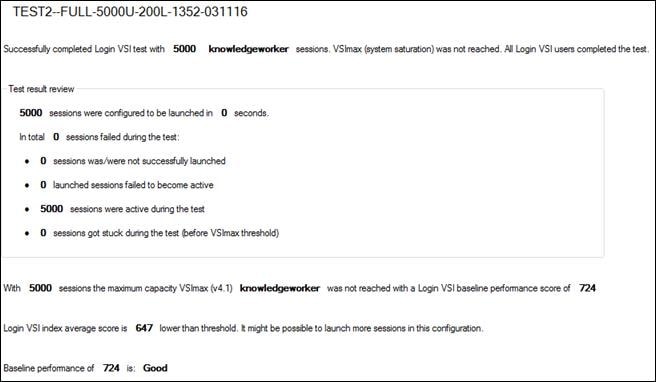
Automatic Login VSI Report
| Testname | TEST2--FULL-5000U-200L-1352-031116 |
| Test Description |
|
| VSImax v4 | 5000 Sessions & Baseline 724 ms |
| Benchmark mode | Disabled |
| VSI Treshold reached? | NO |
| VSIbaseline average response time (ms) | 724 |
| VSImax average response time threshold (ms) | 1724 |
| VSImax threshold was reached at sessions | WAS NOT REACHED |
| VSI response time threshold headroom | 2104 |
| Sessions not responding | 0 |
| Corrected VSImax is | 5000 |
| Total Sessions configured | 5000 |
| Total Sessions successfully launched | 5000 |
| Total Timeframe of test in seconds | 2880 |
| Average session launch interval in seconds | 0.58 |
| Amount of active launchers during test | 200 |
| Average session capacity per launcher | 25 |
VSI response time overview
| VSI response time @ 50 Sessions | 799 |
| VSI response time @ 100 Sessions | 762 |
| VSI response time @ 150 Sessions | 748 |
| VSI response time @ 200 Sessions | 739 |
| VSI response time @ 250 Sessions | 737 |
| VSI response time @ 300 Sessions | 736 |
| VSI response time @ 350 Sessions | 731 |
| VSI response time @ 400 Sessions | 722 |
| VSI response time @ 450 Sessions | 729 |
| VSI response time @ 500 Sessions | 732 |
| VSI response time @ 550 Sessions | 741 |
| VSI response time @ 600 Sessions | 744 |
| VSI response time @ 650 Sessions | 745 |
| VSI response time @ 700 Sessions | 749 |
| VSI response time @ 750 Sessions | 755 |
| VSI response time @ 800 Sessions | 749 |
| VSI response time @ 850 Sessions | 753 |
| VSI response time @ 900 Sessions | 761 |
| VSI response time @ 950 Sessions | 762 |
| VSI response time @ 1000 Sessions | 771 |
| VSI response time @ 1050 Sessions | 776 |
| VSI response time @ 1100 Sessions | 775 |
| VSI response time @ 1150 Sessions | 775 |
| VSI response time @ 1200 Sessions | 773 |
| VSI response time @ 1250 Sessions | 780 |
| VSI response time @ 1300 Sessions | 780 |
| VSI response time @ 1350 Sessions | 785 |
| VSI response time @ 1400 Sessions | 786 |
| VSI response time @ 1450 Sessions | 787 |
| VSI response time @ 1500 Sessions | 790 |
| VSI response time @ 1550 Sessions | 781 |
| VSI response time @ 1600 Sessions | 780 |
| VSI response time @ 1650 Sessions | 783 |
| VSI response time @ 1700 Sessions | 786 |
| VSI response time @ 1750 Sessions | 788 |
| VSI response time @ 1800 Sessions | 792 |
| VSI response time @ 1850 Sessions | 789 |
| VSI response time @ 1900 Sessions | 792 |
| VSI response time @ 1950 Sessions | 793 |
| VSI response time @ 2000 Sessions | 797 |
| VSI response time @ 2050 Sessions | 805 |
| VSI response time @ 2100 Sessions | 812 |
| VSI response time @ 2150 Sessions | 809 |
| VSI response time @ 2200 Sessions | 806 |
| VSI response time @ 2250 Sessions | 807 |
| VSI response time @ 2300 Sessions | 812 |
| VSI response time @ 2350 Sessions | 816 |
| VSI response time @ 2400 Sessions | 827 |
| VSI response time @ 2450 Sessions | 831 |
| VSI response time @ 2500 Sessions | 831 |
| VSI response time @ 2550 Sessions | 834 |
| VSI response time @ 2600 Sessions | 836 |
| VSI response time @ 2650 Sessions | 838 |
| VSI response time @ 2700 Sessions | 844 |
| VSI response time @ 2750 Sessions | 846 |
| VSI response time @ 2800 Sessions | 846 |
| VSI response time @ 2850 Sessions | 851 |
| VSI response time @ 2900 Sessions | 850 |
| VSI response time @ 2950 Sessions | 850 |
| VSI response time @ 3000 Sessions | 853 |
| VSI response time @ 3050 Sessions | 858 |
| VSI response time @ 3100 Sessions | 862 |
| VSI response time @ 3150 Sessions | 865 |
| VSI response time @ 3200 Sessions | 871 |
| VSI response time @ 3250 Sessions | 870 |
| VSI response time @ 3300 Sessions | 878 |
| VSI response time @ 3350 Sessions | 884 |
| VSI response time @ 3400 Sessions | 890 |
| VSI response time @ 3450 Sessions | 897 |
| VSI response time @ 3500 Sessions | 904 |
| VSI response time @ 3550 Sessions | 911 |
| VSI response time @ 3600 Sessions | 917 |
| VSI response time @ 3650 Sessions | 922 |
| VSI response time @ 3700 Sessions | 927 |
| VSI response time @ 3750 Sessions | 930 |
| VSI response time @ 3800 Sessions | 943 |
| VSI response time @ 3850 Sessions | 947 |
| VSI response time @ 3900 Sessions | 949 |
| VSI response time @ 3950 Sessions | 954 |
| VSI response time @ 4000 Sessions | 959 |
| VSI response time @ 4050 Sessions | 964 |
| VSI response time @ 4100 Sessions | 974 |
| VSI response time @ 4150 Sessions | 979 |
| VSI response time @ 4200 Sessions | 980 |
| VSI response time @ 4250 Sessions | 976 |
| VSI response time @ 4300 Sessions | 976 |
| VSI response time @ 4350 Sessions | 977 |
| VSI response time @ 4400 Sessions | 987 |
| VSI response time @ 4450 Sessions | 996 |
| VSI response time @ 4500 Sessions | 1002 |
| VSI response time @ 4550 Sessions | 1009 |
| VSI response time @ 4600 Sessions | 1018 |
| VSI response time @ 4650 Sessions | 1025 |
| VSI response time @ 4700 Sessions | 1040 |
| VSI response time @ 4750 Sessions | 1050 |
| VSI response time @ 4800 Sessions | 1055 |
| VSI response time @ 4850 Sessions | 1064 |
| VSI response time @ 4900 Sessions | 1076 |
| VSI response time @ 4950 Sessions | 1083 |
VSImax Overview
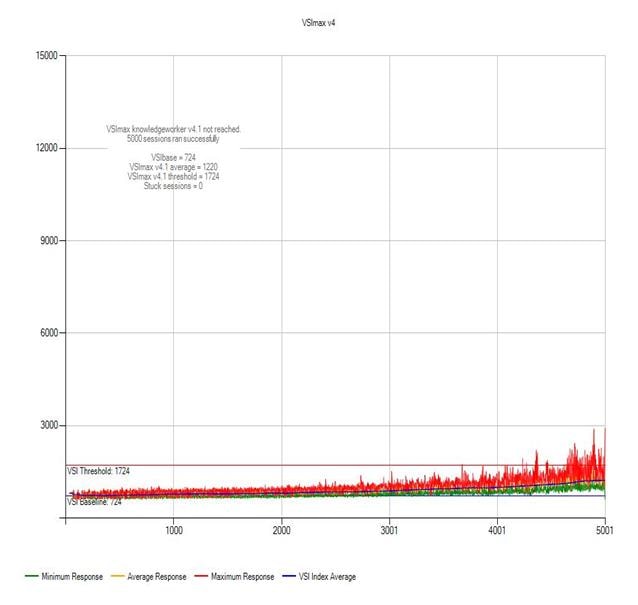
Calculation of large array of random data (CPU)
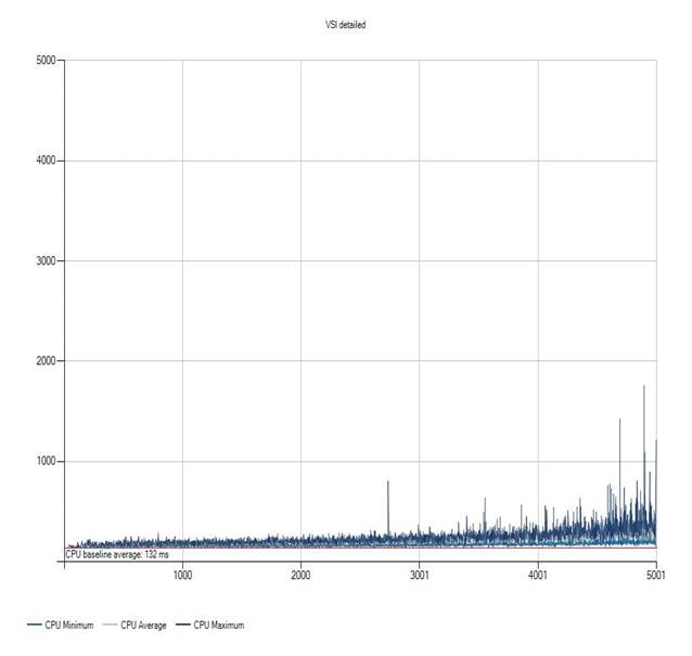
File Copy Text Local (FCTL)
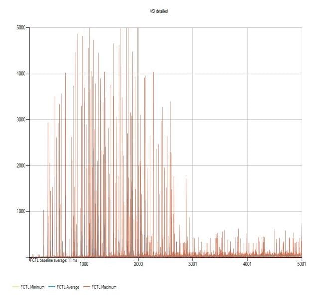
File Copy Text Share (FCTS)
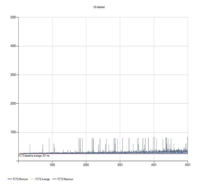
Write the CPU random data file to disk (IO)
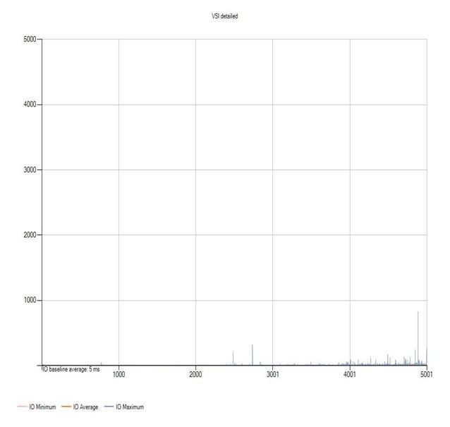
Notepad File Open overview (NFO)
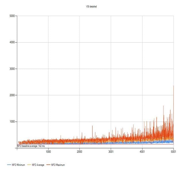
Print Dialogue overview (NFP)
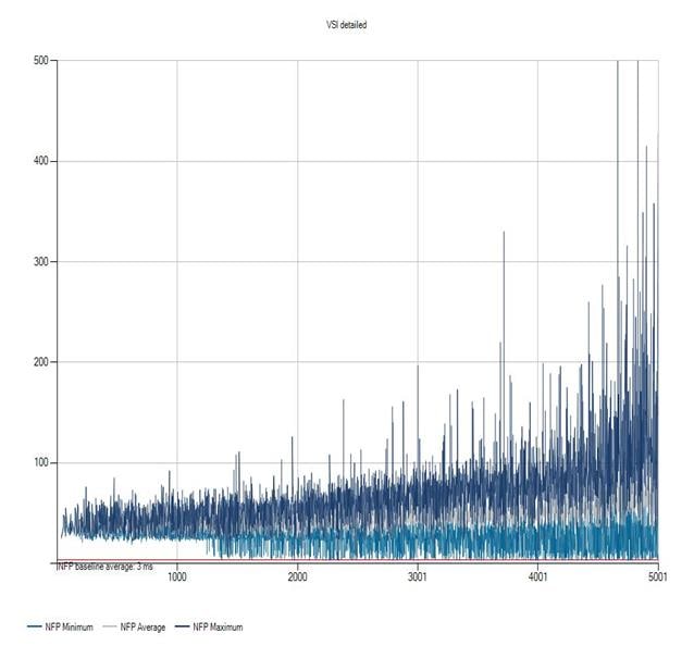
Notepad Load overview (NSLD)
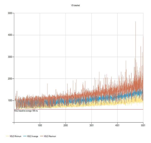
The percentage of memory used by the sessions (UMEM)
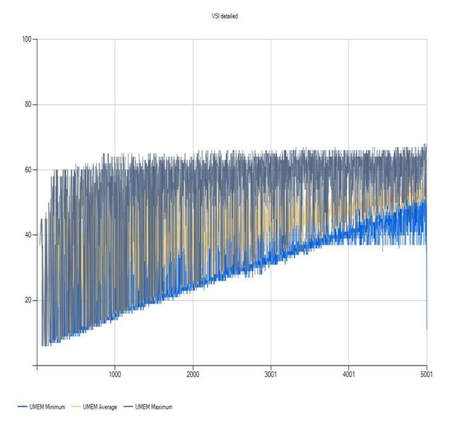
Zip High Compression (ZHC)
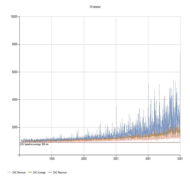
Zip Low Compression (ZLC)
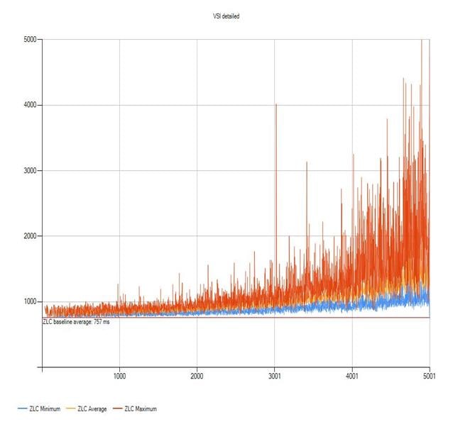
This section provides links to additional information for each partner’s solution component of this document.
§ Cisco UCS B-Series Servers
— http://www.cisco.com/c/en/us/products/servers-unified-computing/ucs-b200-m4-blade-server/index.html
§ Cisco UCS Manager Configuration Guides
§ Related FlexPod with Cisco UCS Guides
— FlexPod Datacenter with VMware vSphere 6.0 Design Guide
§ Site Requirements Guide
http://support.netapp.com/NOW/public/knowledge/docs/hardware/NetApp/site/pdf/site.pdf
§ Clustered Data ONTAP High-Availability Configuration Guide
https://library.netapp.com/ecmdocs/ECMP1367947/html/index.html
§ Clustered Data ONTAP Network Management Guide
https://library.netapp.com/ecmdocs/ECMP1401193/html/index.html
§ Clustered Data ONTAP Software Setup Guide
https://library.netapp.com/ecmdocs/ECMP1368696/html/index.html
§ Storage Subsystem Configuration Guide
http://www.netapp.com/us/system/pdf-reader.aspx?pdfuri=tcm:10-126326-16&m=tr-3838.pdf
§ Advance Drive Partitioning FAQ
https://fieldportal.netapp.com/Core/DownloadDoc.aspx?documentID=147099&contentID=293748
§ NetApp All - Flash FAS Solution For Persistent and Nonpersistent Desktops with Citrix XenDesktop and XenApp
http://www.netapp.com/us/media/tr-4342.pdf
§ FlexPod Datacenter with VMware vSphere 6.0 Design Guide
http://www.cisco.com/c/en/us/td/docs/unified_computing/ucs/UCS_CVDs/flexpod_esxi60_n9k_design.html
§ FlexPod Datacenter with VMware vSphere 6.0
http://www.cisco.com/c/en/us/td/docs/unified_computing/ucs/UCS_CVDs/flexpod_esxi60_n9k.html
§ Clustered Data ONTAP NFS Best Practice and Implementation Guide
http://www.netapp.com/us/media/tr-4067.pdf
§ NetApp Data Compression and Deduplication Data ONTAP 8.3.1 and Above
http://www.netapp.com/us/media/tr-4476.pdf
§ TR-4070 Flash Pool Design and Implementation Guide
http://www.netapp.com/us/system/pdf-reader.aspx?pdfuri=tcm:10-60637-16&m=tr-4070.pdf
§ TR-4182 Ethernet Storage Design Considerations and Best Practices for Clustered Data ONTAP Configurations
http://www.netapp.com/us/media/tr-4182.pdf
§ TR-4138 Design Guide for Citrix XenDesktop on NetApp Storage
http://www.netapp.com/us/system/pdf-reader.aspx?pdfuri=tcm:10-108557-16&m=tr-4138.pdf
§ TR-4191: Best Practice Guide for Clustered Data ONTAP 8.2 & 8.3 Windows File Services
http://www.netapp.com/us/system/pdf-reader.aspx?pdfuri=tcm:10-111337-16&m=tr-4191.pdf
§ TR-3437: Storage Subsystem Resiliency Guide
http://www.netapp.com/us/media/tr-3437.pdf
§ TR-3732: Citrix XenServer and NetApp Storage Best Practices
http://www.netapp.com/us/system/pdf-reader.aspx?pdfuri=tcm:10-104657-16&m=tr-3732.pdf
§ FAS3200-series documentation
https://now.netapp.com/NOW/knowledge/docs/hardware/filer/210-05224+A0.pdf
§ Disk Shelf Installation and Setup section of the DS4243 Disk Shelf Overview
https://library.netapp.com/ecm/ecm_get_file/ECMP1115547
§ Instructions for Downloading and Installing Disk Firmware
https://support.netapp.com/NOW/cgi-bin/diskfwmustread.cgi/download/tools/diskfw/
§ SAS Disk Shelves Universal SAS and ACP Cabling Guide
https://now.netapp.com/NOW/knowledge/docs/hardware/filer/215-05500_A0.pdf
§ TR-3902: Guidelines for Virtual Desktop Storage Profiling
http://www.netapp.com/us/system/pdf-reader.aspx?m=tr-3902.pdf&cc=us
§ TR-3802 Ethernet Storage Best Practices
http://www.netapp.com/us/media/tr-3802.pdf
§ Citrix XenDesktop and XenApp reference documentation
— http://docs.citrix.com/en-us/xenapp-and-xendesktop/7-7.html
— XenDesktop 7.0 Handbook http://support.citrix.com/article/CTX139331
— XenDesktop 7.0 Blueprint http://support.citrix.com/article/CTX138981
§ Microsoft Windows and Citrix optimization guides for virtual desktops
— http://support.citrix.com/article/CTX125874
— http://support.citrix.com/article/CTX140375
— http://support.citrix.com/article/CTX117374
§ VMware vSphere 6.0 documentation
— https://www.vmware.com/support/pubs/vsphere-esxi-vcenter-server-6-pubs.html
Frank Anderson, Senior Solutions Architect, Cisco Systems, Inc.
Frank Anderson is a Senior Solutions Architect at Cisco Systems with over 20 years of experience working in the technology industry. Of those, 18 have been focused on Citrix products working at various Fortune 500 companies (ranging from Healthcare, Entertainment Electric Utilities and Technology). Throughout his career he has held various types of roles ranging from server administration, consulting, sales, technical marketing, strategic alliances director, and solutions architecture. His current role at Cisco is focused on building Virtual Desktop and Application Solutions with responsibilities that include solutions validation, strategic alliances support, technical content creation, and performance testing/benchmarking.
Chris Rodriguez, Senior Technical Marketing Engineer, NetApp
Chris Rodriguez (C-Rod) is a Senior Technical Marketing Engineer at NetApp, who has been involved with VDI since late 1990’s. Chris has professional services experience with implementing VDI products on NetApp storage with many customers. In addition, Chris has over 15 years of Enterprise Storage experience and he has architected, designed and implemented storage at many large enterprise customers. Currently, Chris works for the Convergence Infrastructure team at NetApp and he has been conducting reference architectures with Cisco UCS servers, Cisco Nexus switches, VMware vSphere ESXi and Citrix XenDesktop on NetApp storage
Acknowledgements
For their support and contribution to the design, validation, and creation of this Cisco Validated Design, we would like to acknowledge the significant contribution and expertise that resulted in developing this document:
§ John George, Reference Architect and Technical Marketing Engineer, Cisco Systems, Inc.
§ Jeff Nichols, Technical Marketing Engineer, Desktop Virtualization Solutions Team, Cisco Systems, Inc.
§ Chris Gebhardt, VDI Product Manager, NetApp Inc.
§ David Arnette, Technical Marketing Engineer, NetApp Inc.
§ Bhavik Desai, Performance Engineer, NetApp Inc.
 Feedback