Configuring Mode 1 on Cisco Intersight
Use these steps to configure the RoCE v2 Mode 1 interface on Cisco Interisght.
To avoid possible RDMA packet drops, ensure same no-drop COS is configured across the network. The following steps allows you to configure a no-drop class in System QoS policies and use it for RDMA supported interfaces.
For Cisco UCS M8 C-Series or X-Series servers, the VIC 15000 series is supported, while the Cisco UCS VIC 1400 Series, 14000 Series is not compatible with M8 servers.
Procedure
|
Step 1 |
Navigate to CONFIGURE > Policies. Click Create Policy, select UCS Domain platform type, search or choose System QoS, and click Start. |
||
|
Step 2 |
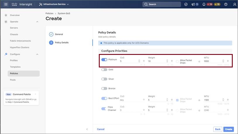
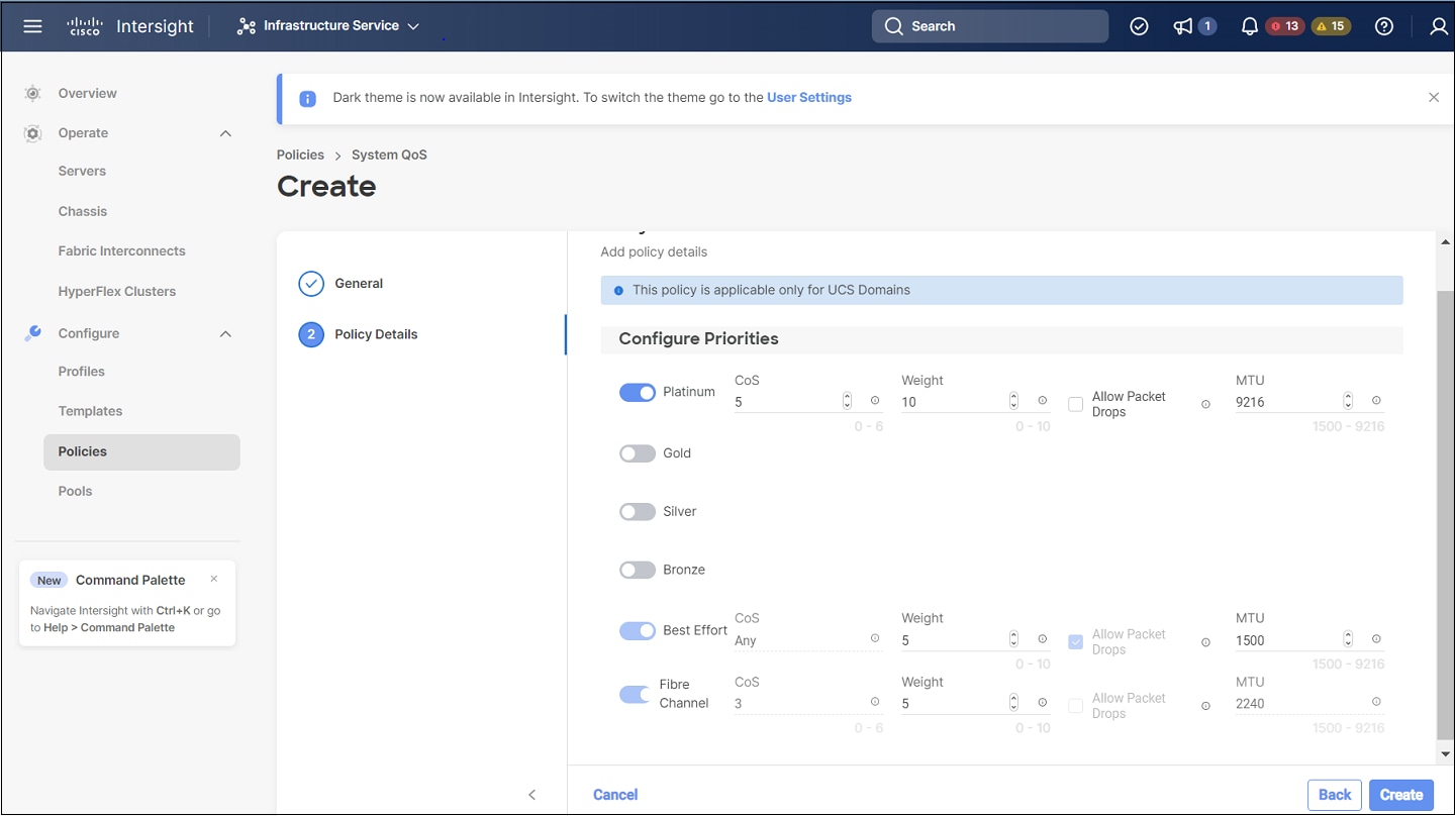
In the General page, enter the policy name and click Next, and then in the Policy Details page, configure the property setting for System QoS policy as follows:
|
||
|
Step 3 |
Click Create |
||
|
Step 4 |
Associate the System QoS policy to the Domain Profile and deploy. 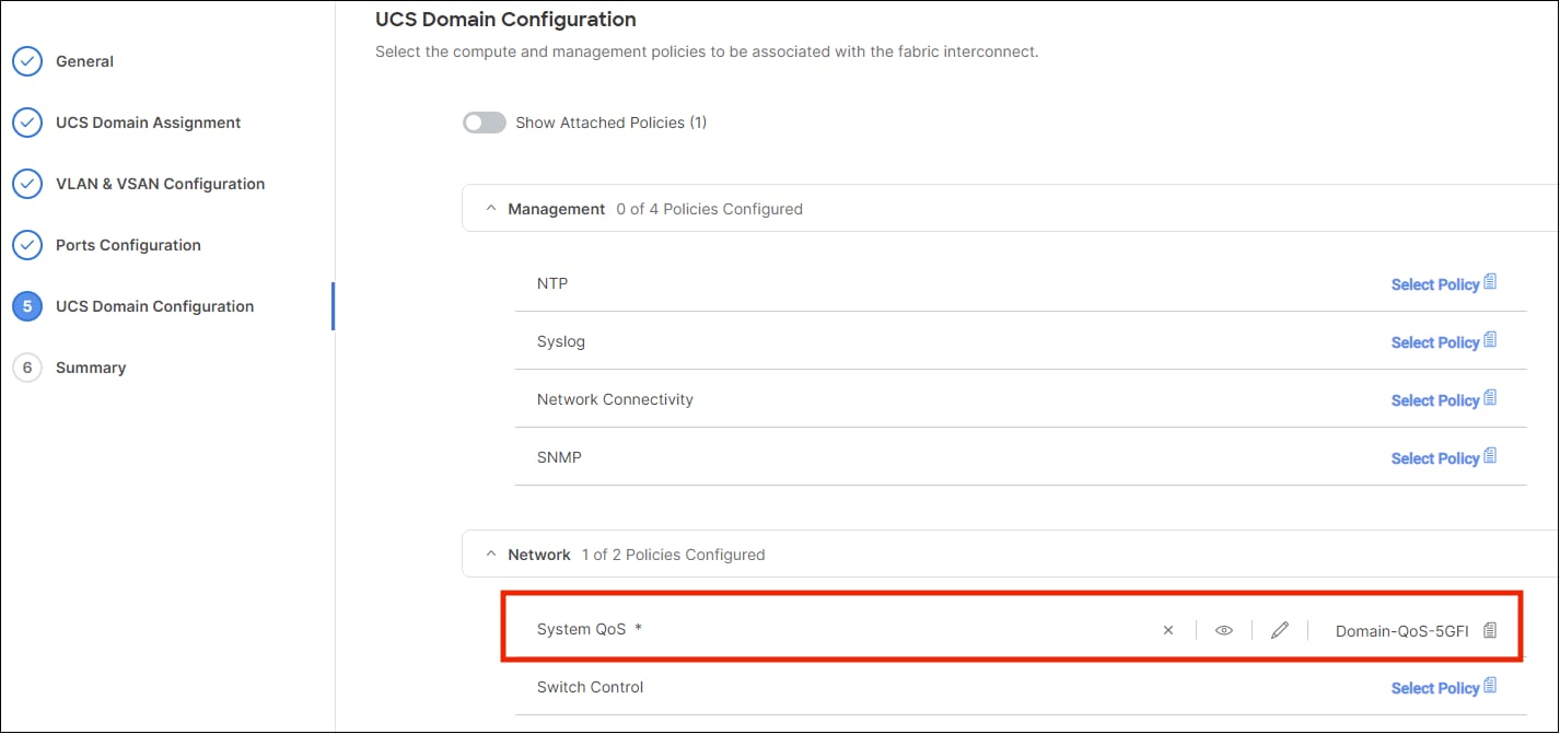
|
The System QoS Policy is successfully created and deployed to the Domain Profile.
What to do next
Configure the server profile with RoCE v2 vNIC settings in LAN Connectivity policy.
Enabling RoCE Settings in LAN Connectivity Policy
Use these steps to configure the RoCE v2 vNIC settings in Mode 1. In Cisco Intersight LAN Connectivity policy, you can enable the RoCE settings on Ethernet QoS policy and Ethernet Adapter policy for Mode 1 configuration as follows:
Procedure
|
Step 1 |
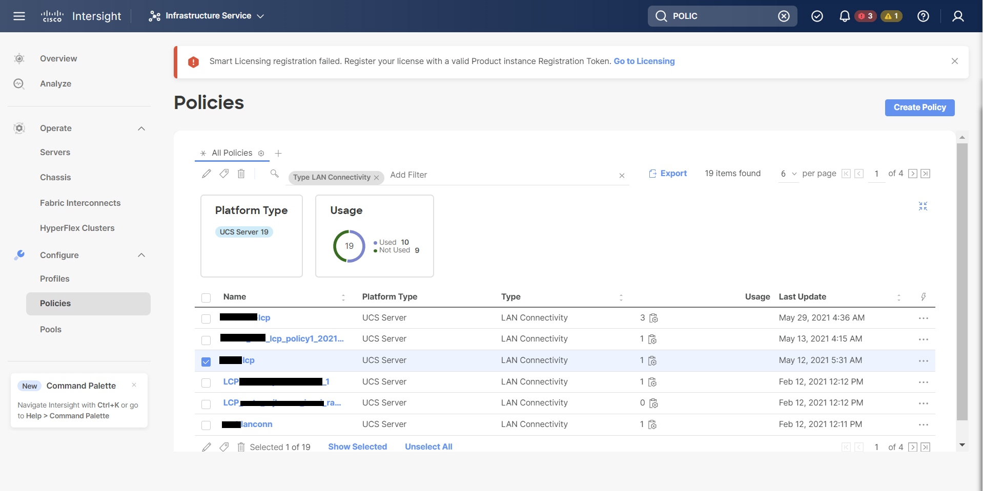
Navigate to CONFIGURE > Policies. Click Create Policy, select UCS Server platform type, search or choose LAN Connectivity policy, and click Start. |
||||
|
Step 2 |
In the policy General page, enter the policy name, select the Target Platform as UCS Server (Standalone) or UCS Server (FI-Attached), and click Next. |
||||
|
Step 3 |
In the Policy Details page, click Add vNIC to create a new vNIC. |
||||
|
Step 4 |
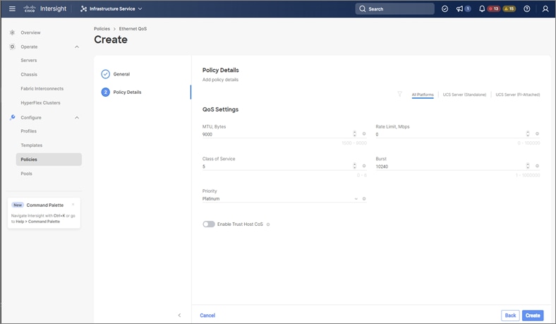
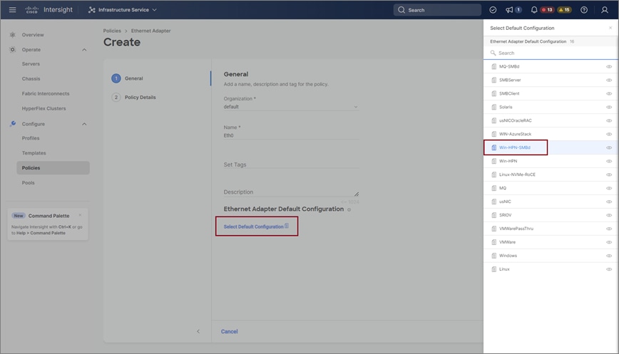
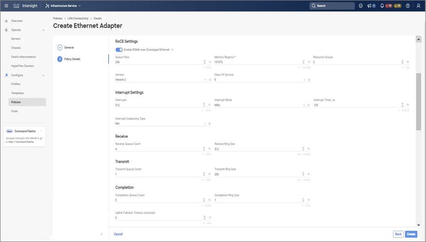
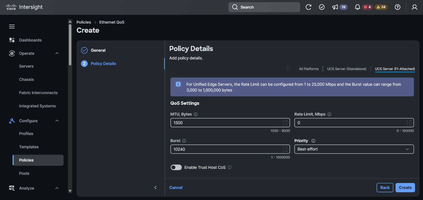
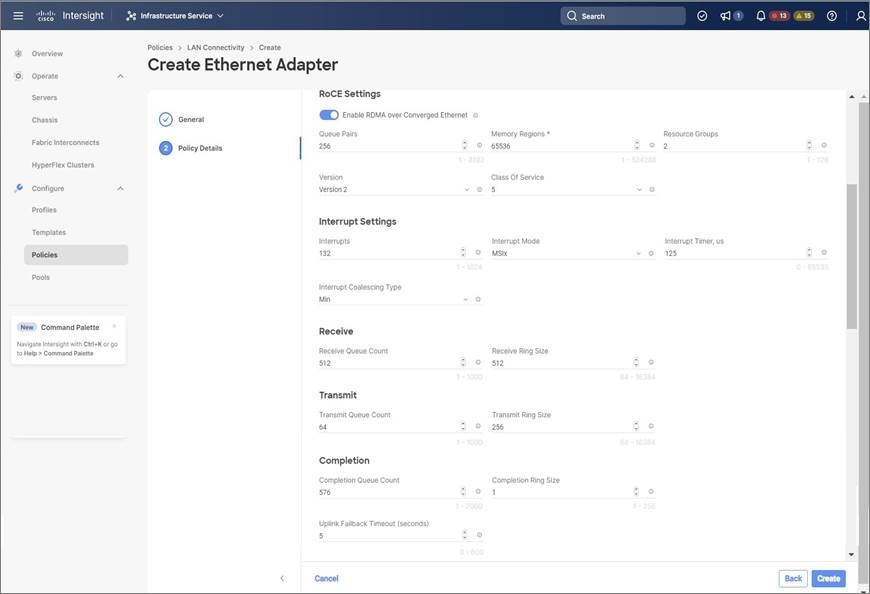
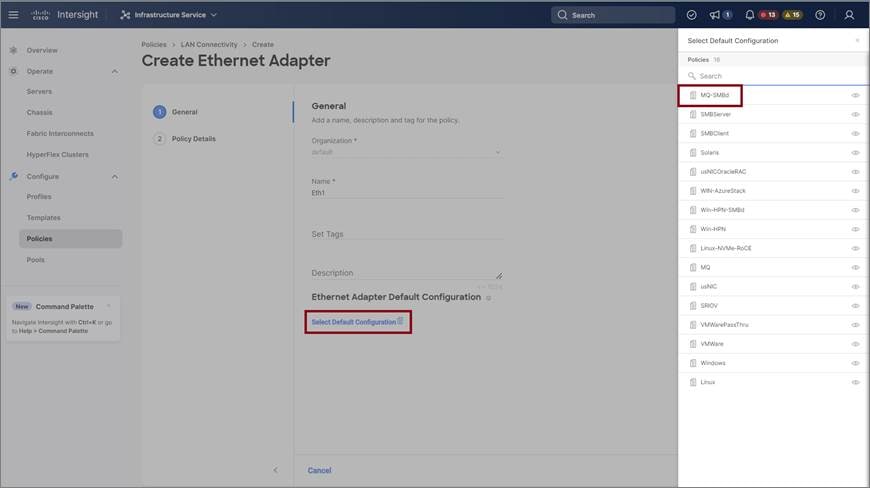
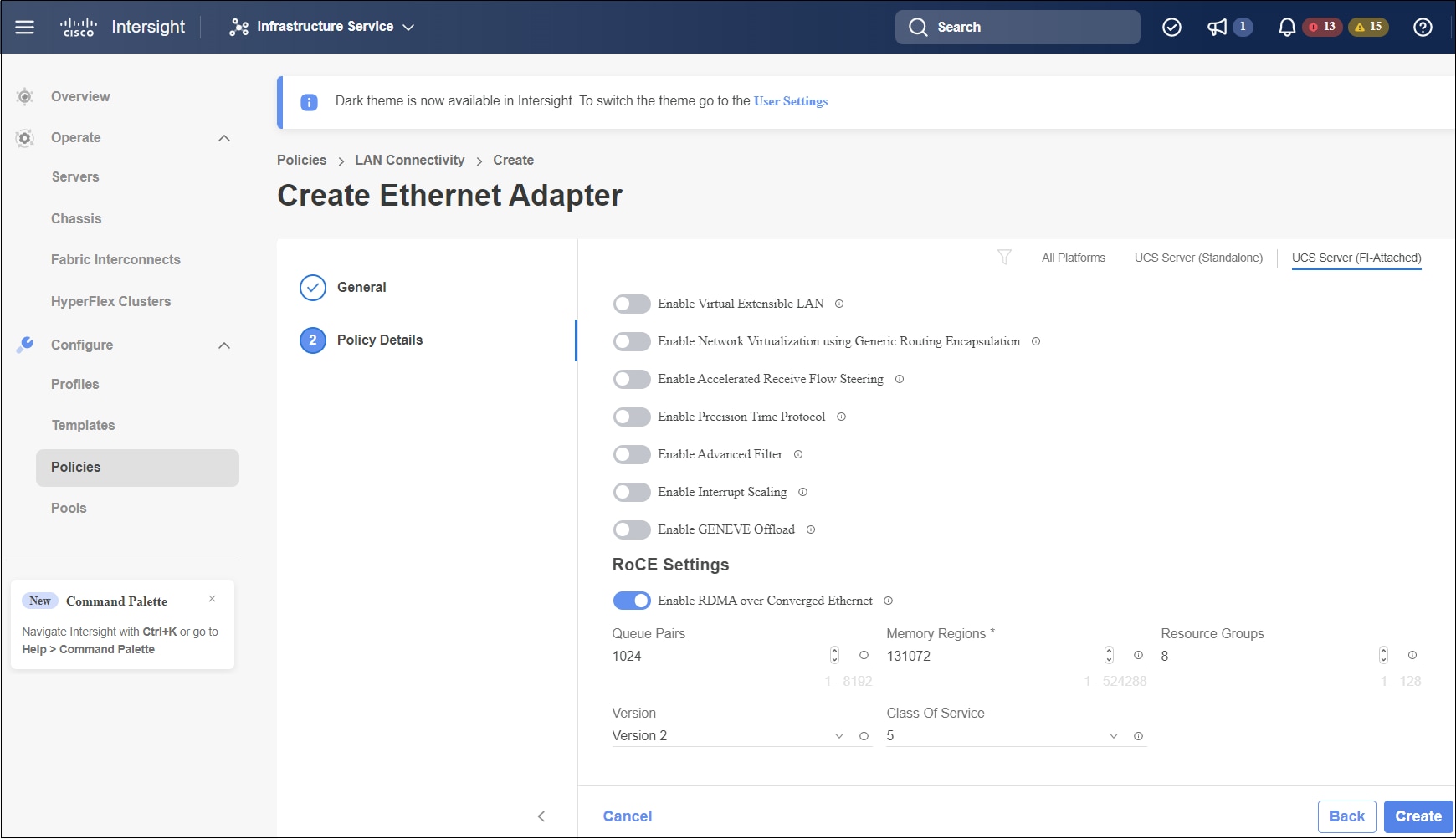
In the Add vNIC page, follow the configuration parameters to enable the RoCE vNIC settings:
|
||||
|
Step 5 |
Click Create to complete the LAN Connectivity policy with RoCE v2 property settings. |
||||
|
Step 6 |
Associate the LAN Connectivity policy to the server profile and deploy.
|
The LAN Connectivity policy with the Ethernet QoS policy and Ethernet Adapter policy vNIC setting is successfully created and the server profile is deployed to enable RoCE v2 configuration.
What to do next
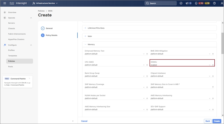
Once the policy configuration for RoCE v2 is complete, proceed to enable IOMMU in the BIOS policy.


 Feedback