- Preface
- Overview of the Cisco MGX 8850 RPM
- Preparing to Install the Cisco MGX 8850 RPM
- Installing the Cisco MGX 8850 RPM
- Cabling Cisco MGX 8850 RPM Port Adapters
- Configuring the Cisco MGX 8850 RPM
- MPLS and VPN for the MGX 8850 RPM, Version 1.1
- Maintaining the Cisco MGX 8850 RPM
- Cable and Connector Specifications
- Accessing the RPM Command-Line Interface
- Booting the RPM
- Configuring the RPM
- Configuring Port Adapter Interfaces
Configuring the Cisco MGX 8850 RPM
This chapter describes how to complete a basic configuration of the Cisco MGX 8850 Route Processor Module (RPM), provides procedures for configuring ATM, Ethernet, Fast Ethernet and FDDI port adapter interfaces, permanent virtual circuits (PVCs) and the connections between the RPM and the PXM and either service modules or other RPMs. This chapter contains the following sections:
•![]() Accessing the RPM Command-Line Interface
Accessing the RPM Command-Line Interface
•![]() Configuring Port Adapter Interfaces
Configuring Port Adapter Interfaces
•![]() Configuring Virtual Circuits on the RPM
Configuring Virtual Circuits on the RPM
•![]() Configuring Connections between the RPM and Other Devices
Configuring Connections between the RPM and Other Devices
•![]() Setting Up Connections Between Other Devices and the PXM
Setting Up Connections Between Other Devices and the PXM
•![]() Viewing FRSM, CESM and AUSM Connections Through the PXM
Viewing FRSM, CESM and AUSM Connections Through the PXM
•![]() Verifying Network Connectivity
Verifying Network Connectivity
This chapter provides information to get the RPM up and running. Detailed software configuration information is available in the Cisco IOS configuration and command reference publications, which are available on the Cisco Documentation CD-ROM.
Accessing the RPM Command-Line Interface
To configure the RPM, you must access the command-line interface (CLI) of the RPM.
The RPM CLI can be accessed using any of the following three methods:
•![]() Console port on the front of the RPM
Console port on the front of the RPM
The RPM has an RJ-45 connector on the front of the card module. If you configure the RPM on site, connect a console terminal (an ASCII terminal or a PC running terminal emulation software) directly to the console port on your RPM using an RS-232 to RJ-45 cable for CLI access (see "Installing the Cisco MGX 8850 RPM"). The console port is the only way to access the RPM CLI when the card module is first installed into an MGX 8850 chassis.
•![]() cc from another MGX 8850 card
cc from another MGX 8850 card
After initial configuration, you can also configure the RPM through the PXM. You can access the RPM CLI by using the cc (change card) command from any of the other cards in the MGX 8850 switch. The ATM switch interface on the RPM must be enabled before you can use the cc command.
•![]() Telnet from a workstation, PC or another router
Telnet from a workstation, PC or another router
After initial configuration, you can also configure the RPM remotely via telnet. After the RPM is installed and has PVCs to other RPMS or routers in the network, you can telnet to the RPM CLI remotely from these other devices. To connect a modem to the auxiliary port on the RPM see "Installing the Cisco MGX 8850 RPM".
Booting the RPM

Note ![]() To power cycle the RPM, turn off the MGX 8850 system, wait five seconds, then turn it on again. Note that turning off the MGX 8850 chassis will affect other installed cards. Alternatively, remove and reinstall the RPM. You can also cycle the RPM by typing the command resetcd [card_number] from the PXM. Note that card_number should be the slot number of the RPM to reboot. Omitting the card number resets the entire system. Also you may power cycle the RPM via the Command Line Interface. The Cisco IOS CLI command is reload.
To power cycle the RPM, turn off the MGX 8850 system, wait five seconds, then turn it on again. Note that turning off the MGX 8850 chassis will affect other installed cards. Alternatively, remove and reinstall the RPM. You can also cycle the RPM by typing the command resetcd [card_number] from the PXM. Note that card_number should be the slot number of the RPM to reboot. Omitting the card number resets the entire system. Also you may power cycle the RPM via the Command Line Interface. The Cisco IOS CLI command is reload.
Each time you turn on power to the RPM (insert the RPM into the MGX 8850), it goes through the following boot sequence:
1. ![]() The RPM goes through power-on self-test diagnostics to verify basic operation of the CPU, memory, and interfaces.
The RPM goes through power-on self-test diagnostics to verify basic operation of the CPU, memory, and interfaces.
2. ![]() The system bootstrap software (boot image) executes and searches for a valid Cisco IOS image (the RPM operating system software).
The system bootstrap software (boot image) executes and searches for a valid Cisco IOS image (the RPM operating system software).
The source of the Cisco IOS image is determined by the configuration register setting. The factory-default setting for the configuration register is 0x2102 which means the RPM will first look for the IOS image in bootflash.
However, since the RPM-A normally has bootflash only large enough to hold the bootstrap image and not the entire IOS operating system image, boot system configuration commands must be used to override the default boot system and specify a Cisco IOS image file on a TFTP server or the PXM C: drive.
For the RPM-B the bootflash contains the entire IOS operating system image.
Note ![]() If the customer purchases an upgrade to the RPM-A from 4MB to 8MB or to 20MB flash, then bootflash can hold a full image (two in the 20MB case) and the IOS image can operate from bootflash. The RPM-B already contains 16MB flash.
If the customer purchases an upgrade to the RPM-A from 4MB to 8MB or to 20MB flash, then bootflash can hold a full image (two in the 20MB case) and the IOS image can operate from bootflash. The RPM-B already contains 16MB flash.
3. ![]() If after five attempts the boot system configuration commands each fail to find a valid IOS image on a TFTP server or on the PXM C: drive, and no valid IOS image is found in bootflash, the RPM reverts to rommon mode (which is used to install or upgrade a Cisco IOS image).
If after five attempts the boot system configuration commands each fail to find a valid IOS image on a TFTP server or on the PXM C: drive, and no valid IOS image is found in bootflash, the RPM reverts to rommon mode (which is used to install or upgrade a Cisco IOS image).
4. ![]() If a valid Cisco IOS image is found, then the RPM searches for a valid configuration file.
If a valid Cisco IOS image is found, then the RPM searches for a valid configuration file.
5. ![]() If a valid configuration file is not found in NVRAM, the RPM runs the System Configuration Dialog so you can configure it manually. For normal RPM operation, there must be a valid Cisco IOS image on a TFTP server, the PXM C: drive, or in bootflash, and a configuration file in NVRAM.
If a valid configuration file is not found in NVRAM, the RPM runs the System Configuration Dialog so you can configure it manually. For normal RPM operation, there must be a valid Cisco IOS image on a TFTP server, the PXM C: drive, or in bootflash, and a configuration file in NVRAM.
The first time you boot the RPM, you need to configure the RPM interfaces and then save the configuration to a file in NVRAM. Proceed to the next section, "Booting the RPM From the PXM" and the section, "Configuring the RPM," for instructions.
Booting the RPM From the PXM
The IOS image should be stored on the PXM hard drive. To confirm this, make sure you are in the /RPM directory and use the ls command to list the contents of the directory. You should see a file named "xxx" which is the IOS image.
The following are PXM commands illustrating this command sequence:
NODENAME.1.7.PXM.a > cd C:RPM
NODENAME.1.7.PXM.a > ls
.
..
rpm-is-mz.120-4.0.1.T
In the file system :
total space : 3176712 K bytes
free space : 3067819 K bytes
NODENAME.1.7.PXM.a >
If this image is not there you will need to use the TFTP file-transfer application to load the image to the PXM hard drive.
The following is an TFTP example:
marka-u5:4> ls -l rpm-is-mz.120-4.0.1.T
-rw-r--r-- 1 marka eng 4560820 Apr 2 12:16 rpm-is-mz.120-4.0.1.T
marka-u5:5> tftp 172.29.37.154
tftp> bin
tftp> put rpm-is-mz.120-4.0.1.T RPM/rpm-is-mz.120-4.0.1.T
Sent 4560820 bytes in 41.2 seconds
tftp> q
marka-u5:6>
To load the IOS image from the PXM hard drive, the RPM must be configured to do so.
Before the RPM can load the IOS image from the PXM, the RPM's ATM switch interface must first be enabled. Use the Console port on the RPM to boot the RPM from Flash so that you can configure its ATM switch interface.
In configuration mode type interface switch slot/1 to access the interface configuration. Type no shutdown to activate the interface.
The following illustrated how to enable the RPM's ATM interface:
RPM(boot)#config term
Enter configuration commands, one per line. End with CNTL/Z.
RPM(boot)(config)#interface Switch9/1
RPM(boot)(config-if)#no shutdown
RPM(boot)(config-if)#
00:06:55:%LINK-3-UPDOWN:Interface Switch9/1, changed state to up
00:06:56:%LINEPROTO-5-UPDOWN:Line protocol on Interface Switch9/1,
changed sta
te to up
RPM(boot)(config-if)#^Z
RPM(boot)#
00:07:01:%SYS-5-CONFIG_I:Configured from console by console
RPM(boot)#
Now, use boot system configuration commands to override the default boot setting. Type the following configuration command to configure the RPM to boot from the PXM:
MGX8850-RPM (config)# boot system c:filename
Then reload the RPM and boot the Cisco IOS from the PXM disk.
Note ![]() Put the RPM's Cisco IOS image in the RPM directory of the PXM hard disk with the filename specified in the RPM boot command.
Put the RPM's Cisco IOS image in the RPM directory of the PXM hard disk with the filename specified in the RPM boot command.
To verify the accessibility of the PXM C:drive from the RPM, issue the following privileged-level EXEC command:
MGX8850-RPM# dir c:
Directory of c:/
-rw- 5584092 Oct 19 1999 15:39:54 rpm-js-mz.120-4.T
-rw- 1680448 Oct 19 1999 15:39:54 rpm-boot-mz.120-2.T
No space information available
********
Configuring the RPM
You can configure the RPM using Configuration Mode—Recommended if you are familiar with Cisco IOS commands.

Timesaver ![]() Obtain the correct network addresses from your system administrator or consult your network plan to determine correct addresses before you begin to configure the RPM.
Obtain the correct network addresses from your system administrator or consult your network plan to determine correct addresses before you begin to configure the RPM.
If you would like a quick review of the Cisco IOS software, refer to the section "Cisco IOS Software Basics" later in this chapter.
Basic Configuration Example
System Bootstrap, Version 11.3(19980311:221233) [phsu-120 237], DEVELOPMENT
SOFTWARE
Copyright (c) 1994-1998 by cisco Systems, Inc.
RPM platform with 32768 Kbytes of main memory
Self decompressing the image :
################################################################################
###################################################### [OK]
Restricted Rights Legend
Use, duplication, or disclosure by the Government is
subject to restrictions as set forth in subparagraph
(c) of the Commercial Computer Software - Restricted
Rights clause at FAR sec. 52.227-19 and subparagraph
(c) (1) (ii) of the Rights in Technical Data and Computer
Software clause at DFARS sec. 252.227-7013.
cisco Systems, Inc.
170 West Tasman Drive
San Jose, California 95134-1706
Cisco Internetwork Operating System Software
IOS (tm) RPM Software (RPM-BOOT-M), Version 12.0(2)T, RELEASE SOFTWARE (fc1)
Copyright (c) 1986-1998 by cisco Systems, Inc.
Compiled Thu 10-Dec-98 22:51 by dschwart
Image text-base: 0x600088E0, data-base: 0x603F6000
Waiting for bootack from remote router ...
Received bootack from remote router
cisco RPM (NPE150) processor with 26624K/6144K bytes of memory.
R4700 processor, Implementation 33, Revision 1.0 (512KB Level 2 Cache)
Last reset from power-on
X.25 software, Version 3.0.0.
4 Ethernet/IEEE 802.3 interface(s)
1 ATM network interface(s)
125K bytes of non-volatile configuration memory.
4096K bytes of packet SRAM memory.
8192K bytes of Flash internal SIMM (Sector size 256K).
--- System Configuration Dialog ---
Would you like to enter the initial configuration dialog? [yes/no]: yes
At any point you may enter a question mark '?' for help.
Use ctrl-c to abort configuration dialog at any prompt.
Default settings are in square brackets '[]'.
Basic management setup configures only enough connectivity
for management of the system, extended setup will ask you
to configure each interface on the system
Would you like to enter basic management setup? [yes/no]: yes
Configuring global parameters:
Enter host name [Router]: rpm_slot4
The enable secret is a password used to protect access to
privileged EXEC and configuration modes. This password, after
entered, becomes encrypted in the configuration.
Enter enable secret: <enable secret>
The enable password is used when you do not specify an
enable secret password, with some older software versions, and
some boot images.
Enter enable password: <enable password>
The virtual terminal password is used to protect
access to the router over a network interface.
Enter virtual terminal password: <line password>
Current interface summary
Any interface listed with OK? value "NO" does not have a valid configuration
Interface IP-Address OK? Method Status
Protocol
Ethernet4/1/1 unassigned NO unset up up
Ethernet4/1/2 unassigned NO unset up up
Ethernet4/1/3 unassigned NO unset up up
Ethernet4/1/4 unassigned NO unset up up
Switch4/1 unassigned NO unset up up
Enter interface name used to connect to the
management network from the above interface summary: Switch4/1
Configuring interface Switch4/1:
Configure IP on this interface? [yes]: no
The following configuration command script was created:
hostname rpm_slot4
enable secret 5 $1$wlCg$SChBT8vszwNb86iKFM9G61
enable password <enable password>
line vty 0 4
password <line password>
!
no ip routing
!
interface Ethernet1/1
shutdown
no ip address
!
interface Ethernet1/2
shutdown
no ip address
!
interface Ethernet1/3
shutdown
no ip address
!
interface Ethernet1/4
shutdown
no ip address
!
interface Switch4/1
no shutdown
no ip address
!
end
[0] Go to the IOS command prompt without saving this config.
[1] Return back to the setup without saving this config.
[2] Save this configuration to nvram and exit.
Enter your selection [2]:
Building configuration...
Use the enabled mode 'configure' command to modify this configuration.
Press RETURN to get started!
00:00:09: %LINK-3-UPDOWN: Interface Switch4/1, changed state to up
00:00:10: %LINEPROTO-5-UPDOWN: Line protocol on Interface Switch4/1,
changed state to up
00:00:19: %LINK-3-UPDOWN: Interface Ethernet1/1, changed state to up
00:00:19: %LINK-3-UPDOWN: Interface Ethernet1/2, changed state to up
00:00:19: %LINK-3-UPDOWN: Interface Ethernet1/3, changed state to up
00:00:19: %LINK-3-UPDOWN: Interface Ethernet1/4, changed state to up
00:00:20: %LINEPROTO-5-UPDOWN: Line protocol on Interface Ethernet1/1,
changed state to up
00:00:20: %LINEPROTO-5-UPDOWN: Line protocol on Interface Ethernet1/2,
changed state to up
00:00:20: %LINEPROTO-5-UPDOWN: Line protocol on Interface Ethernet1/3,
changed state to up
00:00:20: %LINEPROTO-5-UPDOWN: Line protocol on Interface Ethernet1/4,
changed state to up
00:02:04: %LINK-5-CHANGED: Interface Ethernet1/1, changed state to
administratively down
00:02:04: %LINK-5-CHANGED: Interface Ethernet1/2, changed state to
administratively down
00:02:04: %LINK-5-CHANGED: Interface Ethernet1/3, changed state to
administratively down
00:02:04: %LINK-5-CHANGED: Interface Ethernet1/4, changed state to
administratively down
00:02:04: %SYS-5-RESTART: System restarted --
Cisco Internetwork Operating System Software
IOS (tm) RPM Software (RPM-BOOT-M), Version 12.0(2)T, RELEASE SOFTWARE (fc1)
Copyright (c) 1986-1998 by cisco Systems, Inc.
Compiled Thu 10-Dec-98 22:51 by dschwart
00:02:05: %LINEPROTO-5-UPDOWN: Line protocol on Interface Ethernet1/1,
changed state to down
00:02:05: %LINEPROTO-5-UPDOWN: Line protocol on Interface Ethernet1/2,
changed state to down
00:02:05: %LINEPROTO-5-UPDOWN: Line protocol on Interface Ethernet1/3,
changed state to down
00:02:05: %LINEPROTO-5-UPDOWN: Line protocol on Interface Ethernet1/4,
changed state to down
rpm_slot4(boot)>
Configuring Port Adapter Interfaces
Once port adapter cable connections have been made (refer to "Cabling Cisco MGX 8850 RPM Port Adapters" for connector descriptions and cable attachment instructions) and basic configuration on the RPM is completed, ATM, Ethernet, Fast Ethernet and FDDI port adapter interfaces on the RPM must be configured. This is then followed by configuration of permanent virtual circuits (PVCs) and the connections between the RPM and the PXM and either service modules or other RPMs.
Preparing to Configure Port Adapter Interfaces
If you want to configure interfaces in a new RPM or if you want to change the configuration of an existing interface, be prepared with the information you will need, such as the following:
•![]() Protocols you plan to route on each new interface.
Protocols you plan to route on each new interface.
•![]() Internet protocol (IP) addresses if you plan to configure the interfaces for IP routing.
Internet protocol (IP) addresses if you plan to configure the interfaces for IP routing.
•![]() Whether the new interfaces will use bridging.
Whether the new interfaces will use bridging.
•![]() Whether the new interfaces will use LAN.
Whether the new interfaces will use LAN.
The configure command requires privileged-level access to the EXEC command interpreter, which usually requires a password. Contact your system administrator if necessary to obtain EXEC-level access.
Identifying Chassis Slot, Port Adapter Slot, and Interface Port Numbers
The following section describes how to identify chassis slot, port adapter slot, and interface port numbers on the RPM for all port adapter interface types.
RPM Port Adapter Interface Ports
Physical port addresses specify the actual physical location of each interface port, regardless of the type, on the RPM. In the RPM, this address is composed of a three-part number in the format chassis-slot/port adapter slot number/interface port number, as follows:
•![]() The first number identifies the chassis slot in which the RPM is installed. This number is assigned to the RPM during the initial configuration.
The first number identifies the chassis slot in which the RPM is installed. This number is assigned to the RPM during the initial configuration.
•![]() The second number identifies the port adapter slot in which the port adapter is installed, either upper (1) or lower (2) port adapter.
The second number identifies the port adapter slot in which the port adapter is installed, either upper (1) or lower (2) port adapter.
•![]() The third number identifies the interface port(s) on the port adapter.
The third number identifies the interface port(s) on the port adapter.
You can also identify port adapter interface ports by physically checking the slot/interface port location on the front of the RPM or by using show commands to display information about a specific interface or all interfaces in the RPM.
Configuring the ATM Interface
Note ![]() All port adapters on the RPM are removable except for the ATM port adapter. The ATM interface is always port #1.
All port adapters on the RPM are removable except for the ATM port adapter. The ATM interface is always port #1.
This section provides the procedure for a basic interface configuration.
Press Return after each step unless otherwise noted. At any time you can exit the privileged level and return to the user level by entering disable at the prompt as follows:
RPM-3# disable
RPM-3>
Use the following procedure to perform a basic configuration:
Step 1 ![]() At the privileged-level prompt, enter configuration mode and specify that the console terminal will be the source of the configuration subcommands, as follows:
At the privileged-level prompt, enter configuration mode and specify that the console terminal will be the source of the configuration subcommands, as follows:
RPM-3# configure terminal
Enter configuration commands, one per line. End with CNTL/Z.
RPM-3(config)#
Step 2 ![]() At the prompt: enter the subcommand interface to specify the interface to be configured, followed by switch to specify the internal ATM interface, then slot/port (for slot of the MGX 8850 chassis where the RPM is located, and for port number on the port adapter). The example that follows show the atm interface as 1 in the RPM in slot 5 of the MGX 8850:
At the prompt: enter the subcommand interface to specify the interface to be configured, followed by switch to specify the internal ATM interface, then slot/port (for slot of the MGX 8850 chassis where the RPM is located, and for port number on the port adapter). The example that follows show the atm interface as 1 in the RPM in slot 5 of the MGX 8850:
RPM-3(config)# interface switch 5/1
Step 3 ![]() If IP routing is enabled on the system, you can assign an IP address and subnet mask to the interface with the ip address configuration subcommand, as in the following example:
If IP routing is enabled on the system, you can assign an IP address and subnet mask to the interface with the ip address configuration subcommand, as in the following example:
RPM-3(config-if)# ip address 192.168.1.10 255.255.255.0
Step 4 ![]() Add any additional configuration subcommands required to enable routing protocols and set the interface characteristics.
Add any additional configuration subcommands required to enable routing protocols and set the interface characteristics.
Step 5 ![]() Change the shutdown state to up and enable the interface as follows:
Change the shutdown state to up and enable the interface as follows:
RPM-3(config-if)# no shutdown
Step 6 ![]() When you have completed the configuration, press Ctrl-Z to exit configuration mode.
When you have completed the configuration, press Ctrl-Z to exit configuration mode.
Step 7 ![]() Write the new configuration to nonvolatile memory as follows:
Write the new configuration to nonvolatile memory as follows:
RPM-3# copy running-config startup-config
[OK]
RPM-3#
Note ![]() Since the switch interface is not removable, it should always be set to no shutdown.
Since the switch interface is not removable, it should always be set to no shutdown.
Note ![]() The ATM interface can be divided subinterfaces as needed. To see how to configure subinterfaces on the ATM switch interface, refer to the section, "Configuring Permanent Virtual Circuits" later in this chapter.
The ATM interface can be divided subinterfaces as needed. To see how to configure subinterfaces on the ATM switch interface, refer to the section, "Configuring Permanent Virtual Circuits" later in this chapter.
Configuring 4E Interfaces
The Ethernet interfaces are configured to allow a connection to a LAN. To configure the interface parameters, you need to know your Ethernet interface network addresses.
Take the following basic configuration steps to configure an Ethernet interface to allow communication over a LAN:
Press Return after each step unless otherwise noted. At any time you can exit the privileged level and return to the user level by entering disable at the prompt as follows:
RPM-3# disable
RPM-3>
Following is an example of a basic configuration procedure:
Step 1 ![]() At the privileged-level prompt, enter configuration mode and specify that the console terminal will be the source of the configuration subcommands, as follows:
At the privileged-level prompt, enter configuration mode and specify that the console terminal will be the source of the configuration subcommands, as follows:
RPM-3# configure terminal
Enter configuration commands, one per line. End with CNTL/Z.
RPM-3(config)#
Step 2 ![]() At the prompt: enter the subcommand interface to specify the interface to be configured, followed by ethernet to specify port adapter type, then slot/card/port (for slot of the MGX 8850 where the RPM resides, upper (1) or lower (2) port adapter, and for port number on the port adapter).
At the prompt: enter the subcommand interface to specify the interface to be configured, followed by ethernet to specify port adapter type, then slot/card/port (for slot of the MGX 8850 where the RPM resides, upper (1) or lower (2) port adapter, and for port number on the port adapter).
Note ![]() The 4E interfaces here are numbered 1, 2, 3, 4 and not 0, 1, 2, 3 as in other IOS platforms.
The 4E interfaces here are numbered 1, 2, 3, 4 and not 0, 1, 2, 3 as in other IOS platforms.
Step 3 ![]() The example that follows is the 2 interface of the lower ethernet port adapter in the RPM in slot 5 of the MGX 8850:
The example that follows is the 2 interface of the lower ethernet port adapter in the RPM in slot 5 of the MGX 8850:
RPM-3(config)# interface e 5/2/2
Step 4 ![]() If IP routing is enabled on the system, you can assign an IP address and subnet mask to the interface with the ip address configuration subcommand, as in this example:
If IP routing is enabled on the system, you can assign an IP address and subnet mask to the interface with the ip address configuration subcommand, as in this example:
RPM-3(config-int)# ip address 1.1.1.10 255.255.255.0
Step 5 ![]() Add any additional configuration subcommands required to enable routing protocols and set the interface characteristics.
Add any additional configuration subcommands required to enable routing protocols and set the interface characteristics.
Step 6 ![]() Change the shutdown state to up and enable the interface as follows:
Change the shutdown state to up and enable the interface as follows:
RPM-3(config-int)# no shutdown
Step 7 ![]() Configure additional interfaces as required.
Configure additional interfaces as required.
Step 8 ![]() When you have included all of the configuration subcommands to complete the configuration, press Ctrl-Z to exit configuration mode.
When you have included all of the configuration subcommands to complete the configuration, press Ctrl-Z to exit configuration mode.
Step 9 ![]() Write the new configuration to nonvolatile memory as follows:
Write the new configuration to nonvolatile memory as follows:
RPM-3# copy running-config startup-config
[OK]
RPM-3#
To check the interface configuration using show commands, proceed to the section "Checking the Configuration."
Configuring FE Interfaces
The following steps describe a basic configuration. Press Return after each step unless otherwise noted. At any time you can exit the privileged level and return to the user level by entering disable at the prompt as follows:
RPM-3# disable
RPM-3>
Following is an example of a basic configuration procedure:
Step 1 ![]() At the privileged-level prompt, enter configuration mode and specify that the console terminal will be the source of the configuration subcommands, as follows:
At the privileged-level prompt, enter configuration mode and specify that the console terminal will be the source of the configuration subcommands, as follows:
RPM-3# configure terminal
Enter configuration commands, one per line. End with CNTL/Z.
RPM-3(config)#
Step 2 ![]() At the prompt: enter the subcommand interface to specify the interface to be configured, followed by fastethernet to specify port adapter type, then slot/card/port (for slot of the MGX 8850 where the RPM resides, upper (1) or lower (2) port adapter, and for port number on the port adapter). The example that follows is the 1 interface of the upper fastethernet port adapter in the RPM in slot 5 of the MGX 8850:
At the prompt: enter the subcommand interface to specify the interface to be configured, followed by fastethernet to specify port adapter type, then slot/card/port (for slot of the MGX 8850 where the RPM resides, upper (1) or lower (2) port adapter, and for port number on the port adapter). The example that follows is the 1 interface of the upper fastethernet port adapter in the RPM in slot 5 of the MGX 8850:
RPM-3(config)# interface fastethernet 5/1/1
Step 3 ![]() If IP routing is enabled on the system, you can assign an IP address and subnet mask to the interface with the ip address configuration subcommand, as in the following example:
If IP routing is enabled on the system, you can assign an IP address and subnet mask to the interface with the ip address configuration subcommand, as in the following example:
RPM-3(config-if)# ip address 1.1.1.10 255.255.255.0
Step 4 ![]() Add any additional configuration subcommands required to enable routing protocols and set the interface characteristics.
Add any additional configuration subcommands required to enable routing protocols and set the interface characteristics.
Step 5 ![]() Change the shutdown state to up and enable the interface as follows:
Change the shutdown state to up and enable the interface as follows:
RPM-3(config-if)# no shutdown
Step 6 ![]() Configure additional interfaces as required.
Configure additional interfaces as required.
Step 7 ![]() When you have included all of the configuration subcommands to complete the configuration, press Ctrl-Z to exit configuration mode.
When you have included all of the configuration subcommands to complete the configuration, press Ctrl-Z to exit configuration mode.
Step 8 ![]() Write the new configuration to nonvolatile memory as follows:
Write the new configuration to nonvolatile memory as follows:
RPM-3# copy running-config startup-config
[OK]
RPM-3#
This completes the procedure for creating a basic configuration.
Half-duplex operation is the default transmission mode for the FE port adapters. Use the full-duplex command to configure full-duplex operation for the FE port adapters as follows:
RPM-3# configure terminal
Enter configuration commands, one per line. End with CNTL/Z.
RPM-3(config)#
RPM-3(config)# interface fastethernet 5/2/1
RPM-3(config-if)# full-duplex
Ctrl-z
Use the show interfaces fastethernet command to verify that the 2/1 Fast Ethernet interface is now configured for full-duplex operation as follows:
RPM-3# sh int fastethernet 5/2/1
FastEthernet 5/2/1 is administratively up, line protocol is up
(display text omitted)
Encapsulation ARPA, loopback not set, keepalive not set, fdx, 100BaseTX
Use the no full-duplex command to return the interface to half-duplex operation as follows:
RPM-3# config t
Enter configuration commands, one per line. End with CNTL/Z.
RPM-3(config)# int fastethernet 5/2/1
RPM-3(config-if)# no full-duplex
Ctrl-z
RPM-3#
Use the show interfaces fastethernet command to verify that the 2/1 Fast Ethernet interface is now configured for half-duplex operation as follows:
RPM-3# sh int fastethernet 5/2/1
FastEthernet5/2/1 is administratively up, line protocol is up
(display text omitted)
Encapsulation ARPA, loopback not set, keepalive not set, hdx, 100BaseTX
(display text omitted)
The RJ-45 receptacle is the default media type for FE-TX port adapter and the SC receptacle (for fiber-optic connections) is the default media type for FE-FX port adapter. Use the media-type mii command to configure the MII receptacle as the media type for the FE port adapters as follows:
RPM-3# config t
Enter configuration commands, one per line. End with CNTL/Z.
RPM-3(config)# int fa 5/2/1
RPM-3(config-if)# media-type mii
Ctrl-z
RPM-3# sh int fa 5/2/1
FastEthernet2/1 is administratively up, line protocol is up
(display text omitted)
Encapsulation ARPA, loopback not set, keepalive not set, hdx, MII
(display text omitted)
Use the media-type 100 command to return the media type for the FE port adapters to the RJ-45 receptacle or SC receptacle.
To check the interface configuration using show commands, refer to the section "Configuring 4E Interfaces" on page 76.
Configuring FDDI Interfaces
This section provides the procedures for performing a basic configuration of the interfaces on full-duplex FDDI port adapters installed in a RPM.
Press the Return key after each step unless otherwise noted. At any time you can exit the privileged level and return to the user level by entering disable at the prompt as follows:
RPM-3# disable
RPM-3>
Use the following procedure to perform a basic configuration:
Step 1 ![]() At the privileged-level prompt, enter configuration mode. Specify that the console terminal will be the source of the configuration subcommands, as follows:
At the privileged-level prompt, enter configuration mode. Specify that the console terminal will be the source of the configuration subcommands, as follows:
RPM-3# configure terminal
Enter configuration commands, one per line. End with CNTL/Z.
RPM-3(config)#
Step 2 ![]() At the prompt: enter the subcommand interface to specify the interface to be configured, followed by fddi to specify port adapter type, then slot/card/port (for slot of the MGX 8850 where the RPM resides, upper (1) or lower (2) port adapter, and for port number on the port adapter). The example that follows is the 1 interface of the upper fddi port adapter in the RPM in slot 5 of the MGX 8850:
At the prompt: enter the subcommand interface to specify the interface to be configured, followed by fddi to specify port adapter type, then slot/card/port (for slot of the MGX 8850 where the RPM resides, upper (1) or lower (2) port adapter, and for port number on the port adapter). The example that follows is the 1 interface of the upper fddi port adapter in the RPM in slot 5 of the MGX 8850:
RPM-3(config)# interface fddi 5/1/1
Step 3 ![]() If IP routing is enabled on the system, you can assign an IP address and subnet mask to the interface with the ip address configuration subcommand, as in the following example:
If IP routing is enabled on the system, you can assign an IP address and subnet mask to the interface with the ip address configuration subcommand, as in the following example:
RPM-3(config-if)# ip address 1.1.1.10 255.255.255.0
Step 4 ![]() Add any additional configuration subcommands required to enable routing protocols and set the interface characteristics.
Add any additional configuration subcommands required to enable routing protocols and set the interface characteristics.
Step 5 ![]() Change the shutdown state to up and enable the interface as follows:
Change the shutdown state to up and enable the interface as follows:
RPM-3(config-if)# no shutdown
Step 6 ![]() Configure additional interfaces as required.
Configure additional interfaces as required.
Step 7 ![]() When you have included all of the configuration subcommands to complete the configuration, press Ctrl-Z to exit configuration mode.
When you have included all of the configuration subcommands to complete the configuration, press Ctrl-Z to exit configuration mode.
Step 8 ![]() Write the new configuration to nonvolatile memory as follows:
Write the new configuration to nonvolatile memory as follows:
RPM-3# copy running-config startup-config
[OK]
RPM-3#
To check the interface configuration using show commands, refer to the section "Configuring FDDI Interfaces" on page 79.
Note ![]() If you require full-duplex operation, verify that you are using PA-F/FD-SM or PA-F/FD-MM port adapters.
If you require full-duplex operation, verify that you are using PA-F/FD-SM or PA-F/FD-MM port adapters.
Configuring Full-Duplex Operation
Full-duplex operation requires FDDI port adapters PA-F/FD-SM or PA-F/FD-MM.
Full-duplex operation is not the default configuration and must be turned on using the full-duplex command. To turn off full-duplex operation (and enable half-duplex operation) and reset the interface, use the no full-duplex (or half-duplex) command.
Following is an example of configuring an FDDI interface for full-duplex operation using the full-duplex command:
RPM-3# conf t
Enter configuration commands, one per line. End with CNTL/Z.
RPM-3(config)# int fddi 5/2/1
RPM-3(config-if)# full-duplex
Ctrl-z
RPM-3#
Note ![]() If the port adapter does not support full-duplex operation, the following error message will appear: "%FDDI5/2/1 interface does not support full-duplex." If the port adapter does support full-duplex operation, the interface will reset as it changes to full-duplex operation.
If the port adapter does not support full-duplex operation, the following error message will appear: "%FDDI5/2/1 interface does not support full-duplex." If the port adapter does support full-duplex operation, the interface will reset as it changes to full-duplex operation.
The output of the show interfaces fddi slot/card/port command displays the state of the FDDI port adapter interface and the state of full-duplex operation. Following is a partial sample output of this command from an FDDI interface with full-duplex operation enabled:
RPM-3# show int fddi 5/2/1
Fddi5/4/0 is up, line protocol is up
Hardware is MIF68840_MM, address is 0060.7054.8808 (bia 0060.7054.8808)
Internet address is 2.1.1.3/24
MTU 4470 bytes, BW 100000 Kbit, DLY 100 usec, rely 255/255, load 9/255
Encapsulation SNAP, loopback not set, keepalive not set
ARP type: SNAP, ARP Timeout 04:00:00
FDX supported, FDX enabled, FDX state is *
where *, in the last line, could be idle, request, confirm, or operation, depending on the state the FDDI interface was in when the show interfaces command is entered.
When full-duplex operation is turned off using the no full-duplex (or half-duplex) command, the last line of the preceding display includes the following information: FDX supported, FDX disabled. If the port adapter does not support full-duplex, the message FDX NOT supported is displayed.
Checking the Configuration
After configuring the new interface, use the show commands to display the status of the new interface or all interfaces and the ping command to check connectivity.
Using Show Commands to Verify the New Interface Status
The following steps use show commands to verify that the new interfaces are configured and operating correctly.
Step 1 ![]() Use the show version command to display the system hardware configuration. Ensure that the list includes the new interfaces.
Use the show version command to display the system hardware configuration. Ensure that the list includes the new interfaces.
Step 2 ![]() Display all the current port adapters and their interfaces with the show controllers command.
Display all the current port adapters and their interfaces with the show controllers command.
Step 3 ![]() Specify one of the new interfaces with the show interfaces port adapter type slot/card/interface command and verify that the first line of the display specifies the interface with the correct slot number. Also verify that the interface and line protocol are in the correct state: up or down.
Specify one of the new interfaces with the show interfaces port adapter type slot/card/interface command and verify that the first line of the display specifies the interface with the correct slot number. Also verify that the interface and line protocol are in the correct state: up or down.
Step 4 ![]() Display the protocols configured for the entire system and specific interfaces with the show protocols command. If necessary, return to configuration mode to add or remove protocol routing on the system or specific interfaces.
Display the protocols configured for the entire system and specific interfaces with the show protocols command. If necessary, return to configuration mode to add or remove protocol routing on the system or specific interfaces.
Step 5 ![]() Display the running configuration file with the show running-config command.
Display the running configuration file with the show running-config command.
Step 6 ![]() Display the configuration stored in NVRAM using the show startup-config command. Verify that the configuration is accurate for the system and each interface.
Display the configuration stored in NVRAM using the show startup-config command. Verify that the configuration is accurate for the system and each interface.
If the interface is down and you configured it as up, or if the displays indicate that the hardware is not functioning properly, ensure that the network interface is properly connected and terminated. If you still have problems bringing the interface up, contact a service representative for assistance. For detailed software configuration information, refer to the Cisco IOS configuration and command reference publications. These publications are available on the Documentation CD-ROM that came with your RPM, or you can order printed copies.
Using Show Commands to Display Interface Information
To display information about a specific interface, use the show interfaces command with the interface type and port address in the format show interfaces [type slot/card/port] for the MGX 8850 RPM.
Note ![]() For complete command descriptions and examples for all of the supported platforms, refer to the publications listed in the Preface About This Guidein the section, "Objectives."
For complete command descriptions and examples for all of the supported platforms, refer to the publications listed in the Preface About This Guidein the section, "Objectives."
RPM Show Interfaces Command
Following is an example of how the show interfaces [type slot/card/port] command displays status information (including the chassis physical slot, card number and port address) for the interfaces you specify. In these examples, the four Ethernet 10BASE-T interfaces (1-4) are in the lower port adapter in the RPM in slot 4 of the MGX 8850 (interfaces are administratively shut down until you enable them).
rpm_slot4#sh int e 4/2/1
Ethernet2/1 is administratively down, line protocol is down
Hardware is AmdP2, address is 00c0.0023.84d0 (bia 00c0.0023.84d0)
MTU 1500 bytes, BW 10000 Kbit, DLY 1000 usec,
reliablility 255/255, txload 1/255, rxload 1/255
Encapsulation ARPA, loopback not set, keepalive set (10 sec)
ARP type:ARPA, ARP Timeout 04:00:00
Last input never, output never, output hang never
Last clearing of "show interface" counters never
Queueing strategy:fifo
Output queue 0/40, 0 drops; input queue 0/75, 0 drops
5 minute input rate 0 bits/sec, 0 packets/sec
5 minute output rate 0 bits/sec, 0 packets/sec
0 packets input, 0 bytes, 0 no buffer
Received 0 broadcasts, 0 runts, 0 giants, 0 throttles
0 input errors, 0 CRC, 0 frame, 0 overrun, 0 ignored, 0 abort
0 input packets with dribble condition detected
35 packets output, 5510 bytes, 0 underruns
0 output errors, 0 collisions, 0 interface resets
0 babbles, 0 late collision, 0 deferred
0 lost carrier, 0 no carrier
0 output buffer failures, 0 output buffers swapped out
rpm_slot4#sh int e 4/2/2
Ethernet2/2 is up, line protocol is up
Hardware is AmdP2, address is 00c0.0023.84d1 (bia 00c0.0023.84d1)
Internet address is 172.29.37.141/24
MTU 1500 bytes, BW 10000 Kbit, DLY 1000 usec,
reliablility 255/255, txload 1/255, rxload 1/255
Encapsulation ARPA, loopback not set, keepalive set (10 sec)
ARP type:ARPA, ARP Timeout 04:00:00
Last input 00:00:01, output 00:00:00, output hang never
Last clearing of "show interface" counters never
Queueing strategy:fifo
Output queue 0/40, 0 drops; input queue 0/75, 0 drops
5 minute input rate 0 bits/sec, 1 packets/sec
5 minute output rate 0 bits/sec, 0 packets/sec
5753 packets input, 399324 bytes, 0 no buffer
Received 5711 broadcasts, 0 runts, 0 giants, 0 throttles
0 input errors, 0 CRC, 0 frame, 0 overrun, 0 ignored, 0 abort
0 input packets with dribble condition detected
249 packets output, 26248 bytes, 0 underruns
0 output errors, 1 collisions, 1 interface resets
0 babbles, 0 late collision, 7 deferred
0 lost carrier, 0 no carrier
0 output buffer failures, 0 output buffers swapped out
rpm_slot4#sh int e 4/2/3
Ethernet2/3 is administratively down, line protocol is down
Hardware is AmdP2, address is 00c0.0023.84d2 (bia 00c0.0023.84d2)
MTU 1500 bytes, BW 10000 Kbit, DLY 1000 usec,
reliablility 255/255, txload 1/255, rxload 1/255
Encapsulation ARPA, loopback not set, keepalive set (10 sec)
ARP type:ARPA, ARP Timeout 04:00:00
Last input never, output never, output hang never
Last clearing of "show interface" counters never
Queueing strategy:fifo
Output queue 0/40, 0 drops; input queue 0/75, 0 drops
5 minute input rate 0 bits/sec, 0 packets/sec
5 minute output rate 0 bits/sec, 0 packets/sec
0 packets input, 0 bytes, 0 no buffer
Received 0 broadcasts, 0 runts, 0 giants, 0 throttles
0 input errors, 0 CRC, 0 frame, 0 overrun, 0 ignored, 0 abort
0 input packets with dribble condition detected
35 packets output, 5510 bytes, 0 underruns
0 output errors, 0 collisions, 0 interface resets
0 babbles, 0 late collision, 0 deferred
0 lost carrier, 0 no carrier
0 output buffer failures, 0 output buffers swapped out
rpm_slot4#sh int e 4/2/4
Ethernet2/4 is administratively down, line protocol is down
Hardware is AmdP2, address is 00c0.0023.84d3 (bia 00c0.0023.84d3)
MTU 1500 bytes, BW 10000 Kbit, DLY 1000 usec,
reliablility 255/255, txload 1/255, rxload 1/255
Encapsulation ARPA, loopback not set, keepalive set (10 sec)
ARP type:ARPA, ARP Timeout 04:00:00
Last input never, output never, output hang never
Last clearing of "show interface" counters never
Queueing strategy:fifo
Output queue 0/40, 0 drops; input queue 0/75, 0 drops
5 minute input rate 0 bits/sec, 0 packets/sec
5 minute output rate 0 bits/sec, 0 packets/sec
0 packets input, 0 bytes, 0 no buffer
Received 0 broadcasts, 0 runts, 0 giants, 0 throttles
0 input errors, 0 CRC, 0 frame, 0 overrun, 0 ignored, 0 abort
0 input packets with dribble condition detected
35 packets output, 5510 bytes, 0 underruns
0 output errors, 0 collisions, 0 interface resets
0 babbles, 0 late collision, 0 deferred
0 lost carrier, 0 no carrier
0 output buffer failures, 0 output buffers swapped out
Switch4/1 is up, line protocol is up
Hardware is ENHANCED ATM PA
MTU 4470 bytes, sub MTU 4470, BW 149760 Kbit, DLY 80 usec,
reliability 255/255, txload 1/255, rxload 1/255
Encapsulation ATM, loopback not set, keepalive not supported
Encapsulation(s):AAL5
4096 maximum active VCs, 0 current VCCs
VC idle disconnect time:300 seconds
0 carrier transitions
Last input never, output 00:00:00, output hang never
Last clearing of "show interface" counters never
Queueing strategy:fifo
Output queue 0/40, 0 drops; input queue 0/75, 0 drops
5 minute input rate 0 bits/sec, 0 packets/sec
5 minute output rate 0 bits/sec, 0 packets/sec
883 packets input, 42644 bytes, 0 no buffer
Received 0 broadcasts, 0 runts, 0 giants, 0 throttles
0 input errors, 0 CRC, 0 frame, 0 overrun, 0 ignored, 0 abort
918 packets output, 44307 bytes, 0 underruns
0 output errors, 0 collisions, 0 interface resets
0 output buffer failures, 0 output buffers swapped out
With the show interfaces type slot/card/port command, use arguments such as the interface type (ethernet, and so forth), slot, card and the port number (slot/card/port) to display information about a specific Ethernet 10BASE-T interface only.
The show version (or show hardware) command displays the configuration of the system hardware (the number of each port adapter type installed), the software version, the names and sources of configuration files, and the boot images. Following is an example of the show version command:
RPM-3# show version
Cisco Internetwork Operating System Software
IOS (tm) RPM Software (RPM-JS-M), Version 12.0(4)T, RELEASE SOFTWARE (fc1)
Copyright (c) 1986-1999 by cisco Systems, Inc.
Compiled Wed 26-Mar-99 17:14 by marka
Image text-base:0x600088E0, data-base:0x60D74000
ROM:System Bootstrap, Version 11.3(19980311:221233) [phsu-120 237], DEVELOPMENT SOFTWARE
BOOTFLASH:RPM Software (RPM-BOOT-M), Version 12.0(2)T, RELEASE SOFTWARE (fc1)
rpm_slot4 uptime is 28 minutes
System restarted by reload
Running default software
cisco RPM (NPE150) processor with 57344K/8192K bytes of memory.
R4700 processor, Implementation 33, Revision 1.0 (512KB Level 2 Cache)
Last reset from power-on
Bridging software.
X.25 software, Version 3.0.0.
SuperLAT software copyright 1990 by Meridian Technology Corp).
TN3270 Emulation software.
4 Ethernet/IEEE 802.3 interface(s)
1 ATM network interface(s)
125K bytes of non-volatile configuration memory.
4096K bytes of packet SRAM memory.
8192K bytes of Flash internal SIMM (Sector size 256K).
Configuration register is 0x2102
To determine which type of port adapter is installed in your system, use the show diag slot command. Specific port adapter information is displayed, as shown in the following example of an 4E port adapter in port adapter slot 1:
RPM-3# show diag 1
Slot 1:
Ethernet port adapter, 4 ports
port adapter is analyzed
port adapter insertion time 2d09h ago
Hardware revision 1.1 Board revision A0
Serial number 4294967295 Part number 73-1556-04
Test history 0x0 RMA number 00-00-00
EEPROM format version 1
EEPROM contents (hex):
0x20: 01 02 01 01 FF FF FF FF 49 06 14 04 00 00 00 00
0x30: 50 00 00 00 FF FF FF FF FF FF FF FF FF FF FF FF
Proceed to the next section "Using the ping Command" to verify that each interface port is functioning properly.
Using the ping Command
The packet internet groper (ping) command allows you to verify that an interface port is functioning properly and to check the path between a specific port and connected devices at various locations on the network. This section provides brief descriptions of the ping command. After you verify that the system has booted successfully and is operational, you can use this command to verify the status of interface ports.
The ping command sends an echo request out to a remote device at an IP address that you specify. After sending a series of signals, the command waits a specified time for the remote device to echo the signals. Each returned signal is displayed as an exclamation point (!) on the console terminal; each signal that is not returned before the specified time-out is displayed as a period (.). A series of exclamation points (!!!!!) indicates a good connection; a series of periods (.....) or the messages [timed out] or [failed] indicate that the connection failed.
Following is an example of a successful ping command to a remote server with the address 1.1.1.10:
RPM-3# ping 1.1.1.10 <Return>
Type escape sequence to abort.
Sending 5, 100-byte ICMP Echoes to 1.1.1.10, timeout is 2 seconds:
!!!!!
Success rate is 100 percent (5/5), round-trip min/avg/max = 1/15/64 ms
RPM-3#
If the connection fails, verify that you have the correct IP address for the server and that the server is active (powered on). Repeat the ping command.
Configuring Virtual Circuits on the RPM
A VC is a point-to-point connection between two or more devices. This section describes how to configure a PVC originating on the RPM ATM interface and terminating on a service module within a single MGX 8850 or on another RPM.
A VC is established for each ATM end node with which the RPM communicates. The characteristics of the VC are established when the VC is created and include the following:
•![]() Quality of service (QOS)
Quality of service (QOS)
•![]() ATM Adaptation Layer 5 mode (AAL5)
ATM Adaptation Layer 5 mode (AAL5)
•![]() Encapsulation type (LLC/SNAP, MUX, and QSAAL)
Encapsulation type (LLC/SNAP, MUX, and QSAAL)
Each RPM VC supports the following router functions:
•![]() Mulitprotocol
Mulitprotocol
–![]() IP: static route, IGRP, RIP, OSPF, EIGRP
IP: static route, IGRP, RIP, OSPF, EIGRP
–![]() IPX: static route, RIP, EIGRP
IPX: static route, RIP, EIGRP
–![]() XNS: static route, RIP, UB
XNS: static route, RIP, UB
–![]() AppleTalk: RTMP, EIGRP
AppleTalk: RTMP, EIGRP
–![]() CLNS: static route, ISO-IGRP, ISIS
CLNS: static route, ISO-IGRP, ISIS
–![]() Vines: static route, RTP
Vines: static route, RTP
–![]() DECnet: PhaseIV, Phase IV Prime
DECnet: PhaseIV, Phase IV Prime
•![]() Fast switching of IP packets
Fast switching of IP packets
•![]() Pseudobroadcast support for multicast packets
Pseudobroadcast support for multicast packets
Resource Partitioning
Like the other card modules in the MGX 8850 switch, resource partitions must be defined on the RPM. The rpmrscprtn command defines the bandwidth and addressing resources assigned to each controller (PAR, Tag or PNNI).
The rpmrscprtn command is used to modify the resource partitioning on the RPM. It is necessary to use the rpmrscprtn command before you add any PVCs or connections to the RPM because by default all partitions are disabled.
Type in the following command to set up resource partitioning:
RPM-3(config)# rpmrscprtn PAR 100 100 1 255 0 3840 4047
Partition type [par|tag|pnni] Percent ingress [<0-100>] Percent egress [<0-100>] Minimum
VPI [<0-255>] Maximum VPI [<0-255> Minimum VCI [<0-3840>] Maximum VCI [<0-3840>] Number of
LCNs [<0-4047>]
Table 5-1 describes rpmrscprtn command parameters.
Table 5-1 rpmrscprtn Parameter Description
Configuring Permanent Virtual Circuits
All permanent virtual circuits (PVCs) configured into the RPM remain active until the circuit is removed from the configuration. The PVCs also require a permanent connection to the ATM switch. All virtual circuit characteristics apply to PVCs. When a PVC is configured, all the configuration options are passed on to the ATM port adapter. These PVCs are writable into the nonvolatile RAM (NVRAM) as part of the RPM configuration and are used when the RPM image is reloaded.
Each PVC on the RPM is associated with a subinterface. Some subinterfaces support multiple PVCs (multipoint) that do the equivalent of broadcasting. Others only support one PVC (point-to-point). If a point-to-multipoint PVC exists, then that PVC can be used as the sole broadcast PVC for all multicast requests.
Each subinterface is identified as slot/interface.subinterface. The slot is the card slot number of the RPM, the interface is always 1, and the subinterface is a number that identifies the subinterface PVCs on the RPM.
A subinterface is created while in the configuration mode by typing the interface switch command. The IP address is set using the ip address command.
To configure a PVC, you must perform the following tasks:
Step 1 ![]() Create a point-to-point or multipoint subinterface.
Create a point-to-point or multipoint subinterface.
Step 2 ![]() Assign an IP address to the subinterface.
Assign an IP address to the subinterface.
Step 3 ![]() Create an ATM PVC.
Create an ATM PVC.
Step 4 ![]() Define a map list (for multipoint only).
Define a map list (for multipoint only).
Step 5 ![]() Add a connection between the RPM and the PXM.
Add a connection between the RPM and the PXM.
Step 6 ![]() Add the remaining connection segments as needed.
Add the remaining connection segments as needed.
Refer to the document, MGX 8850 Wide Area Switch Installation and Configuration, for more information on creating PVCs on the RPM and the rest of the Cisco 7000 family of routers. Also refer the section, "Configuring Connections between the RPM and Other Devices," in this chapter.
Creating a PVC
When you create a PVC, you create a virtual circuit descriptor (VCD) and attach it to the virtual path identifier (VPI) and virtual channel identifier (VCI). A VCD is an ATM port adapter-specific mechanism that identifies to the ATM port adapter which VPI/VCI to use for a particular packet. The ATM port adapter requires this feature to manage packets for transmission. The number chosen for the VCD is independent of the VPI/VCI used. When you create a PVC, you also specify the AAL and encapsulation. A rate queue is used that matches the default peak and average rate, which are equal, and are specified in kilobits per second. To create a PVC on the ATM port adapter interface, use the atm pvc command. To remove a PVC, use the no form of this command.
atm pvc vcd vpi vci aal-encap
no atm pvc vcd
RPM:
RPM-3(config)# interface switch chassis-slot/1.subinterface interface-type
Where the interface-type is either point-to-point, multipoint or tag.
RPM-3(config-if)# atm pvc 2048 255 128 aal5snap
Note ![]() Since the atm port adapter is internal to the RPM and the interface is logical not physical, you can not remove it. It is always referred to as slot/1.
Since the atm port adapter is internal to the RPM and the interface is logical not physical, you can not remove it. It is always referred to as slot/1.
vcd—A unique index value describing this VC in the range of 1 to MAXVC (defined when setting up resource partitioning). Do not use VCD 1, as this is hardcoded.
vpi—The ATM network VPI to use for this VC in the range of 0 through 255. A VPI of 0 indicates that this PVC is a VCC. A non-0 value indicates that the PVC is a VPC.
vci—The ATM network VCI to use for this VC in the range of 0 through 3,824.
aal-encap—The encapsulation type to use on this VC from the following:
aal5mux—Specifies the MUX-type for this VC. A protocol type must be specified.
aal5snap—LLC/SNAP precedes the protocol datagram.
aal5nlpid—NLPID precedes the protocol datagram.
qsaal—A signaling type VC.
aal5ciscoppp—Used for PPP applications.
The atm pvc command creates PVC n and attaches the PVC to VPI and VCI. The AAL used is specified by aal and encapsulation by encap.
The default for peak rate and average rate is that peak = average, and the PVC is automatically connected to the highest bandwidth rate queue available. For detailed software configuration information, refer to the Cisco IOS configuration and command reference publications. These publications are available on the Documentation CD-ROM that came with your RPM, or you can order printed copies.
Mapping a Protocol Address to a PVC
Cisco IOS software supports a mapping scheme that identifies the ATM address of remote hosts/RPMs. This address can be specified either as a VCD for a PVC or a network service access point (NSAP) address for SVC operation.
Enter mapping commands as groups; multiple map entries can exist in one map list. First create a map list, then associate the list with an interface.
Enter the map-list name command; then enter the protocol, protocol address, and other variables, as follows:
map-list name
protocol-type protocol-address [atm-vc vcd] | atm-nsap nsap-address] [broadcast]
The broadcast keyword specifies that this map entry receives the corresponding protocol broadcast requests to the interface (for example, any network routing protocol updates). If you do not specify broadcast, the ATM software is prevented from sending routing protocol updates to the remote hosts.
After you create the map list, specify the ATM interface to which it applies with the interface command, as follows:
RPM usage:
RPM-3# interface switch 5/1
Associate the map list to an interface with the following command:
map-group name
You can create multiple map lists, but only one map list can be associated with an interface. Different map lists can be associated with different interfaces. The following is an example of the commands to map a list to an interface on a RPM:
RPM-3# interface switch 5/1
ip address 1.1.1.2 255.255.255.0
map-group atm1
atm pvc 2 0 1 aal5snap
!
no ip classless
!
map-list atm1
ip 1.1.1.1 atm-vc 2 broadcast
Note ![]() The RPM can not use VCD=1, since it already uses VCD=1 for the IP connection to the PXM.
The RPM can not use VCD=1, since it already uses VCD=1 for the IP connection to the PXM.
Configuring Connections between the RPM and Other Devices
After configuring port adapters on the RPM, the next step is to configure connections between the RPM and other devices (service modules, other RPMs) via the PXM.
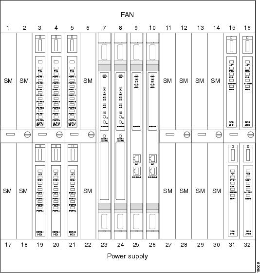
The PXM (the main processor on the MGX 8850) coordinates all communication between the RPM and service modules and other RPMs. See Figure 5-1 for a view of how service modules sit in the MGX 8850 and their physical relationship to the PXM and RPM.
Figure 5-1 Service Modules in the MGX 8850
A complete connection between the RPM and any of these devices includes two parts:
•![]() The half between the RPM and the PXM.
The half between the RPM and the PXM.
•![]() The half between the PXM and the service module or a different RPM.
The half between the PXM and the service module or a different RPM.
Setting Up the RPM Connection to the PXM
Initially, you set up the connection between the RPM and the PXM.
For the RPM in slot 5 connecting to slot 2 perform the following steps:
Step 1 ![]() Set up physical interface:
Set up physical interface:
RPM-3# conf t
RPM-3(config)# int sw5/1
RPM-3(config)# no shut
Step 2 ![]() Set up logical interface:
Set up logical interface:
RPM-3(config)# int sw 5/1.1 point-to-point
ip address 1.0.0.1 255.0.0.0
Step 3 ![]() Set up pvc:
Set up pvc:
RPM-3(config-if)# atm pvc 2 0 1 aal5snap
Step 4 ![]() To get back to the global level, type exit:
To get back to the global level, type exit:
RPM-3(config-if)# exit
RPM-3(config)#
Step 5 ![]() Then, type in the following command to set up resource partitioning:
Then, type in the following command to set up resource partitioning:
RPM-3(config)# rpmrscprtn PAR 100 100 1 255 0 3840 4047
Partition type [par|tag|pnni] Percent ingress [<0-100>] Percent egress [<0-100>] Minimum
VPI [<0-255>] Maximum VPI [<0-255> Minimum VCI [<0-3840>] Maximum VCI [<0-3840>] Number of
LCNs [<0-4047>]
Step 6 ![]() Add a connection to the pvc, either vcc (virtual circuit connection) or vpc (virtual path connection):
Add a connection to the pvc, either vcc (virtual circuit connection) or vpc (virtual path connection):
RPM-3(config)# addcon vcc Switch slot/1[.sub-interface] vci [rname rname] rslot rslot
r_int r_vpi r_vci [master {local | remote}]
or
RPM-3(config)# addcon vpc Switch slot/1[.sub-interface] vpi [rname rname] rslot rslot
r_int r_vpi [master {local | remote}]
slot — RPM slot number
sub-interface — optional sub-interface
vci — Local VCI
vpi — Local VPI
rname — Remote nodename
rslot — Remote slot
r_int — Remote interface, i.e. Switch interface number, or SM port number
r_vpi — Remote VPI
r_vci — Remote VCI
master — Local: make this RPM the master end of the connection. Type master local to make the local RPM you are configuring master. Remote (default): make the other RPM the master end of the connection. Type master remote or hit <cr> to make the far-end RPM master.
Use master local for connections to the PXM or to other SMs, or when connecting to FRSM, PXM for 2- or 3-segment connections. In a local (DAX) RPM-RPM connection, one side must be master.
cost — Maximum connection cost, <1-255>, (default 255)
priority — Routing priority, <0-15>, (default 0)
none |
No restriction (default) |
satellite |
Avoid satellite trunks |
terrestrial |
Avoid terrestrial trunks |
restriction — Restricted Trunk Type
none |
No restriction (default) |
satellite |
Avoid satellite trunks |
terrestrial |
Avoid terrestrial trunks |
rmcr — Remote MCR value, <0-353208>, (default 0; allowed rmcr range will be either <0-rpcr> or <0-0> if rpcr is not explicitly configured)
rpcr — Remote PCR value, <0-353208>, (default 353208)
rutil — Remote percent utilization, <0-100>, (default 100)
util — Connection percent utilization value, <0-100>, (default 100)
Sample RPM-PXM Configuration
Note ![]() Before your can cc over to the RPM you must first log into the RPM via the console port and perform a no shut on the switch interface.
Before your can cc over to the RPM you must first log into the RPM via the console port and perform a no shut on the switch interface.
popeye01.1.7.PXM.a > cc
(session redirected)
RPM configuration
User Access Verification
Password: (cisco)
rpm01>ena
Password: (cisco)
rpm01#conf t
Enter configuration commands, one per line. End with CNTL/Z.
rpm01(config)#int ?
ATM ATM interface
Async Async interface
BVI Bridge-Group Virtual Interface
Cable CMTS interface
Dialer Dialer interface
Ethernet IEEE 802.3
FastEthernet FastEthernet IEEE 802.3
Group-Async Async Group interface
Lex Lex interface
Loopback Loopback interface
Null Null interface
Port-channel Ethernet Channel of interfaces
Switch Switch Virtual Interface
Tunnel Tunnel interface
Virtual-Template Virtual Template interface
Virtual-TokenRing Virtual TokenRing
rpm01(config)#int sw ?
<1-16> Chassis slot number
rpm01(config)#int sw 9/?
<0-1> Switch interface number
rpm01(config)#int sw 9/1?
. <0-1>
rpm01(config)#int sw 9/1.66 ?
multipoint Treat as a multipoint link
point-to-point Treat as a point-to-point link
tag-switching Treat as a tag switching link
<cr>
rpm01(config)#int sw 9/1.66 point
rpm01(config-subif)#ip ?
Interface IP configuration subcommands:
access-group Specify access control for packets
accounting Enable IP accounting on this interface
address Set the IP address of an interface
authentication authentication subcommands
bandwidth-percent Set EIGRP bandwidth limit
broadcast-address Set the broadcast address of an interface
cgmp Enable/disable CGMP
directed-broadcast Enable forwarding of directed broadcasts
dvmrp DVMRP interface commands
hello-interval Configures IP-EIGRP hello interval
helper-address Specify a destination address for UDP broadcasts
hold-time Configures IP-EIGRP hold time
igmp IGMP interface commands
irdp ICMP Router Discovery Protocol
load-sharing Style of load sharing
mask-reply Enable sending ICMP Mask Reply messages
mroute-cache Enable switching cache for incoming multicast packets
mtu Set IP Maximum Transmission Unit
multicast IP multicast interface commands
nat NAT interface commands
nhrp NHRP interface subcommands
rpm01(config-subif)#ip address 6.6.6.6 255.255.255.0
rpm01(config-subif)#atm ?
address-registration Address Registration
arp-server Configure IP ARP Server
auto-configuration ATM interface auto configuration
classic-ip-extensions Specify the type of Classic IP extensions
e164 E164 Configuration
esi-address 7-octet ATM ESI address
ilmi-enable ILMI Configuration
ilmi-keepalive Keepalive polling configuration
lecs-address LECS Address
multipoint-signalling Multipoint Signalling
nsap-address 20-octet ATM NSAP address
pvc Create a PVC
signalling Signalling subcommands
rpm01(config-subif)#atm pvc ?
<1-4095> VCD number
rpm01(config-subif)#atm pvc 66 ?
<0-255> VPI number
rpm01(config-subif)#atm pvc 66 0 ?
<1-65535> VCI number
rpm01(config-subif)#atm pvc 66 0 66 ?
aal5ciscoppp Cisco PPP over AAL5 Encapsulation
aal5mux AAL5+MUX Encapsulation
aal5nlpid AAL5+NLPID Encapsulation
aal5snap AAL5+LLC/SNAP Encapsulation
rpm01(config-subif)#atm pvc 66 0 66 aal5snap ?
<1-155000> Peak rate(Kbps)
inarp Inverse ARP enable
oam OAM loopback enable
<cr>
rpm01(config-subif)#atm pvc 66 0 66 aal5snap
rpm01(config-subif)#exit
rpm01(config)#rpmrscprtn ?
par Partition for PAR
pnni Partition for PNNI
tag Partition for TAG
rpm01(config)#rpmrscprtn par ?
<0-100> Ingress Percent Bandwidth
rpm01(config)#rpmrscprtn par 100 ?
<0-100> Egress Percent Bandwidth
rpm01(config)#rpmrscprtn par 100 100 ?
<0-255> Minimum VPI Value
rpm01(config)#rpmrscprtn par 100 100 0 ?
<0-255> Maximum VPI Value
rpm01(config)#rpmrscprtn par 100 100 0 255 ?
<0-3840> Minimum VCI Value
rpm01(config)#rpmrscprtn par 100 100 0 255 0 ?
<0-3840> Maximum VCI Value
rpm01(config)#rpmrscprtn par 100 100 0 255 0 3840 ?
<0-4047> Number of LCNs
rpm01(config)#rpmrscprtn par 100 100 0 255 0 3840 4047
rpm01(config)#addcon ?
vcc Add a vcc connection
vpc Add a vpc connection
rpm01(config)#addcon vcc ?
Switch Switch Virtual Interface
rpm01(config)#addcon vcc sw ?
<1-16> Chassis slot number
rpm01(config)#addcon vcc sw 9/?
<0-1> Switch interface number
rpm01(config)#addcon vcc sw 9/1?
. <0-1>
rpm01(config)#addcon vcc sw 9/1.66 ?
<1-3824> local VCI value
rpm01(config)#addcon vcc sw 9/1.66 66 ?
rname remote node name
rslot Remote slot number
rpm01(config)#addcon vcc sw 9/1.66 66 rslot ?
<0-30> Remote slot number
rpm01(config)#addcon vcc sw 9/1.66 66 rslot 0 ?
<0-512> Remote interface
rpm01(config)#addcon vcc sw 9/1.66 66 rslot 0 1 ?
<0-255> Remote VPI
rpm01(config)#addcon vcc sw 9/1.66 66 rslot 0 1 66 ?
<0-65535> Remote VCI
rpm01(config)#addcon vcc sw 9/1.66 66 rslot 0 1 ?
<0-255> Remote VPI
rpm01(config)#addcon vcc sw 9/1.66 66 rslot 0 1 0 ?
<0-65535> Remote VCI
rpm01(config)#addcon vcc sw 9/1.66 66 rslot 0 1 0 66 ?
cost Maximum connection cost
master Master end of the ATM connection
priority Routing priority
restriction Restricted Trunk Type
rmcr Connection Remote MCR
rpcr Connection Remote PCR
rutil Connection Remote percent utilization
util Connection precent utilization
<cr>
rpm01(config)#addcon vcc sw 9/1.66 66 rslot 0 1 0 66 master ?
local Local option
remote Remote option
rpm01(config)#addcon vcc sw 9/1.66 66 rslot 0 1 0 66 master local ?
cost Maximum connection cost
priority Routing priority
restriction Restricted Trunk Type
rmcr Connection Remote MCR
rpcr Connection Remote PCR
rutil Connection Remote percent utilization
util Connection precent utilization
<cr>
rpm01(config)#addcon vcc sw 9/1.66 66 rslot 0 1 0 66 master local
Note ![]() This adds a connection to the active PXM.
This adds a connection to the active PXM.
Note ![]() That the RPM is the MASTER and not the slave.
That the RPM is the MASTER and not the slave.
Note ![]() SlotNo. = 0 (zero) which points to the active PXM.
SlotNo. = 0 (zero) which points to the active PXM.
rpm01(config)#exit
rpm01#wr mem
Building configuration...
rpm01#wr t
Building configuration...
Current configuration:
!
version 12.0
no service pad
service timestamps debug uptime
service timestamps log uptime
no service password-encryption
!
hostname rpm01
!
boot system c:rpm-js-mz.120-2.5.T
enable password cisco
!
ip subnet-zero
!
!
!
interface FastEthernet1/1
no ip address
no ip directed-broadcast
shutdown
!
interface Ethernet2/1
no ip address
no ip directed-broadcast
shutdown
!
.
.
!
interface Ethernet2/4
no ip address
no ip directed-broadcast
shutdown
!
interface Switch9/1
no ip address
no ip directed-broadcast
!
!
interface Switch9/1.66 point-to-point
ip address 6.6.6.6 255.255.255.0
no ip directed-broadcast
atm pvc 66 0 66 aal5snap
!
!
ip classless
!
!
!
line con 0
transport input none
line aux 0
line vty 0 4
password cisco
login
!
rpmrscprtn PAR 100 100 0 255 0 3840 4047
addcon vcc switch 9/1.66 66 rslot 0 1 0 66 master local
end
rpm01#cc 7
(session redirected)
PXM configuration
popeye01.1.7.PXM.a > dspcons (connection added is shown in blue)
dspcons
This End Node Name Other End Status
1.1.0.0 popeye01 7.1.10.100 OK
2.1.0.100 popeye01 7.1.0.100 OK
3.1.20.200 popeye01 7.1.20.200 OK
7.1.0.100 popeye01 2.1.0.100 OK
7.1.10.100 popeye01 1.1.0.0 OK
7.1.20.200 popeye01 3.1.20.200 OK
7.1.0.66 popeye01 9.1.0.66 OK
9.1.0.66 popeye01 7.1.0.66 OK
popeye01.1.7.PXM.a > addcon
addcon
ERR: incorrect number of parameters: (not enough)
Syntax: addcon "port_no conn_type local_VPI local_VCI service [mastership]
[remoteConnId]"
port_no -- a number 1..32
conn_type -- a number 1..2 (1: vpc 2: vcc)
local_VPI -- a number 0..4095
local_VCI -- a number 0..65535
service -- a number 1..4 (1:cbr 2:vbr 3:abr 4:ubr)
mastership -- a number 1..2 (1:master 2:slave default:2)
remoteConnId -- a string (format: NodeName.SlotNo.PortNo.VPI.VCI),
required if mastership is 1 (master)
popeye01.1.7.PXM.a > addcon 1 2 0 66 1 2 popeye01.9.1.0.66
addcon 1 2 0 66 1 2 popeye01.9.1.0.66
Connection ID: popeye01.0.1.0.66
Note ![]() This is done to complete the RPM connection.
This is done to complete the RPM connection.
Note ![]() That the PXM is NOT the master but the slave.
That the PXM is NOT the master but the slave.
Setting Up Connections Between Other Devices and the PXM
To complete a RPM-to-service module connection, you then configure the connection between the service module and the PXM.
Service Modules
Service modules can be of various types including FRSM (Frame Relay), AUSM (ATM UNI), CESM (Circuit Emulation) and VISM (Voice).
AUSM
The AUSM-8T1/E1 is a multipurpose card that supports up to 8 T1 or E1 ports.
CESM
The Circuit Emulation Service Module (CESM) emulates leased lines/circuits over an ATM network. It converts DS1/E1 or data streams into CBR AAL1 cells for transport across the network. The T1/E1 versions support either structured or unstructured data transfer on a per-physical interface basis.
VISM
VISM is a multi-DSP co-processing card and software package that adds voice over IP capabilities to the MGX 8850 platform. The MGX 8850 utilizes this new feature card along with LAN/WAN routing capabilities to provide a 192/240 channels gateway for VoIP packetized voice traffic to and from TDM traffic.
FRSM
The Frame Service Module (FRSM) is a two-card set consisting of an FRSM front card (channelized or fractional, T1 or E1, 8 port) and either an 8T1, or 8E1 port adapter. The FRSM converts Frame Relay packets into ATM cells.
Data Forwarding to RPMs
Service modules can be configured to forward data to the RPMs in one of two modes: port forwarding or connection forwarding.
Frame Aggregation: Port Forwarding (FRSM)
In this mode, all frames received on a port are forwarded to the router for L3 processing. For example, a FRSM T1 could be configured for PPP IP access by:
1. ![]() Setting up a frame forwarding (FF) connection from a FRSM T1 port to the RPM cellbus address on VPI/VCI.
Setting up a frame forwarding (FF) connection from a FRSM T1 port to the RPM cellbus address on VPI/VCI.
2. ![]() Configuring the router to terminate PPP frames forwarded over an ATM connection on the ATM Deluxe Port Adaptor port on VCI 0/xFrame-forwarding (a proprietary method whereby all HDLC frames received on a port are converted to ATM AAL5 frames with a null encapsulation and sent over a single VC). Cisco has implemented code to terminate frame-forwarded PPP over ATM.
Configuring the router to terminate PPP frames forwarded over an ATM connection on the ATM Deluxe Port Adaptor port on VCI 0/xFrame-forwarding (a proprietary method whereby all HDLC frames received on a port are converted to ATM AAL5 frames with a null encapsulation and sent over a single VC). Cisco has implemented code to terminate frame-forwarded PPP over ATM.
The data flow for a PPP connection destined for the RPM is shown in the figure below. The packet enters the FRSM module as PPP and is frame forwarded to the RPM. The RPM receives the packet in PPP over ATM because MGX 8850 internal connectivity is ATM. The RPM is running software that understands PPP over ATM encapsulation, allowing the router to reach the IP layer and route the packet to its destination (i.e. the Internet). Packets then destined to the Internet via a WAN network are then sent back to the PXM, and out the ATM uplink.
Figure 5-2 Internal Path of a PPP Packet Destined for RPM
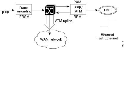
PPP over ATM example
In this example, the FRSM is in slot 18 and RPM A is in slot 12. A serial port on Router B is connected to the FRSM line 1.
***
Router B (connected to line 1 of FRSM) configuration example:
interface Serial5/0
ip address 192.168.100.2 255.255.255.0
encapsulation ppp
***
FRSM configuration (See FRSM documentation for complete command syntax):
Step 1 ![]() Configure the line.
Configure the line.
SQureshi.1.18.FRSM.a> addln 1
Step 2 ![]() Configure a frame-forwarding port on the line.
Configure a frame-forwarding port on the line.
SQureshi.1.18.FRSM.a> addport 1 1 2 1 24 3
Step 3 ![]() Configure a frame-forwarding channel from the port to the RPM.
Configure a frame-forwarding channel from the port to the RPM.
Connect DLCI 1000 on the port to a unique VCI on the RPM, using VPI 0.
SQureshi.1.18.FRSM.a> addcon 1 1000 1536000 5 2 1 2 SQureshi.12.1.0.1001
***
RPM configuration example:
interface Virtual-Template12/1
ip address 192.168.100.12 255.255.255.0
!
interface Switch12/1.100 point-to-point
atm pvc 100 0 1001 aal5ciscoppp Virtual-Template12/1
!
rpmrscprtn par 100 100 0 255 0 3840 4047
addcon vcc Switch 12/1.100 1001 rslot 18 1 0 1000 master local
***
To verify connectivity:
RPM A--
rpm_slot12# sh atm vc 100
Switch12/1.100:VCD:100, VPI:0, VCI:1001
UBR, PeakRate:149760
AAL5-CISCOPPP, etype:0x9, Flags:0xC2A, VCmode:0x0
OAM frequency:0 second(s)
InARP DISABLED
Transmit priority 4
InPkts:57, OutPkts:90, InBytes:1828, OutBytes:2068
InPRoc:57, OutPRoc:90
InFast:0, OutFast:0, InAS:0, OutAS:0
InPktDrops:0, OutPktDrops:0
CrcErrors:0, SarTimeOuts:0, OverSizedSDUs:0
OAM cells received:0
OAM cells sent:0
Status:UP
PPP:Virtual-Access12/1 from Virtual-Template12/1
rpm_slot12#sh int Virtual-Access12/1
Virtual-Access12/1 is up, line protocol is up
Hardware is Virtual Access interface
Internet address is 192.168.100.12/24
MTU 1500 bytes, BW 100000 Kbit, DLY 100000 usec,
reliablility 255/255, txload 1/255, rxload 1/255
Encapsulation PPP, loopback not set
Keepalive set (10 sec)
DTR is pulsed for 5 seconds on reset
LCP Open
Open:IPCP
Bound to Switch12/1.100 VCD:100, VPI:0, VCI:1001
Cloned from virtual-template:1
Last input 00:00:07, output never, output hang never
Last clearing of "show interface" counters 00:06:17
Queueing strategy:fifo
Output queue 0/40, 0 drops; input queue 0/75, 0 drops
5 minute input rate 0 bits/sec, 0 packets/sec
5 minute output rate 0 bits/sec, 0 packets/sec
59 packets input, 1632 bytes, 0 no buffer
Received 59 broadcasts, 0 runts, 0 giants, 0 throttles
0 input errors, 0 CRC, 0 frame, 0 overrun, 0 ignored, 0 abort
92 packets output, 2100 bytes, 0 underruns
0 output errors, 0 collisions, 0 interface resets
0 output buffer failures, 0 output buffers swapped out
0 carrier transitions
rpm_slot12#ping 192.168.100.2
Type escape sequence to abort.
Sending 5, 100-byte ICMP Echos to 192.168.100.2, timeout is 2 seconds:
!!!!!
Success rate is 100 percent (5/5), round-trip min/avg/max = 4/4/8 ms
rpm_slot12#sh ip ro
...
192.168.100.0/24 is variably subnetted, 2 subnets, 2 masks
C 192.168.100.0/24 is directly connected, Virtual-Access12/1
C 192.168.100.2/32 is directly connected, Virtual-Access12/1
Router B --
router_B#sh int s5/0
Serial5/0 is up, line protocol is up
Hardware is M4T
Internet address is 192.168.100.2/24
MTU 1500 bytes, BW 1544 Kbit, DLY 20000 usec,
reliablility 255/255, txload 1/255, rxload 1/255
Encapsulation PPP, crc 16, loopback not set, keepalive set (10 sec)
LCP Open
Listen:CDPCP
Open:IPCP
Last input 00:00:00, output 00:00:00, output hang never
Last clearing of "show interface" counters never
Input queue:0/75/0 (size/max/drops); Total output drops:0
Queueing strategy:weighted fair
Output queue:0/1000/64/0 (size/max total/threshold/drops)
Conversations 0/1/256 (active/max active/max total)
Reserved Conversations 0/0 (allocated/max allocated)
5 minute input rate 0 bits/sec, 0 packets/sec
5 minute output rate 0 bits/sec, 0 packets/sec
35953 packets input, 529169 bytes, 0 no buffer
Received 35639 broadcasts, 0 runts, 1 giants, 0 throttles
211 input errors, 176 CRC, 0 frame, 0 overrun, 0 ignored, 35 abort
36172 packets output, 487073 bytes, 0 underruns
0 output errors, 0 collisions, 2465 interface resets
0 output buffer failures, 0 output buffers swapped out
2475 carrier transitions DCD=up DSR=up DTR=up RTS=up CTS=up
router_B#sh ip ro
...
192.168.100.0/24 is variably subnetted, 2 subnets, 2 masks
C 192.168.100.12/32 is directly connected, Serial5/0
C 192.168.100.0/24 is directly connected, Serial5/0
router_B#ping 192.168.100.12
Type escape sequence to abort.
Sending 5, 100-byte ICMP Echos to 192.168.100.12, timeout is 2 seconds:
!!!!!
Success rate is 100 percent (5/5), round-trip min/avg/max = 4/5/8 ms
FRSM --
SQureshi.1.18.FRSM.a > dsplns
Line Conn Type Status/Coding Length XmtClock Alarm Stats
Type Source Alarm
---- ----- ------------ ------ -------- ------------- -------- ----- -----
18.1 RJ-48 dsx1ESF Ena/dsx1B8ZS 0-131 ft LocalTim No No
18.2 RJ-48 dsx1ESF Dis/dsx1B8ZS 0-131 ft LocalTim
18.3 RJ-48 dsx1ESF Dis/dsx1B8ZS 0-131 ft LocalTim
18.4 RJ-48 dsx1ESF Dis/dsx1B8ZS 0-131 ft LocalTim
18.5 RJ-48 dsx1ESF Dis/dsx1B8ZS 0-131 ft LocalTim
18.6 RJ-48 dsx1ESF Dis/dsx1B8ZS 0-131 ft LocalTim
18.7 RJ-48 dsx1ESF Dis/dsx1B8ZS 0-131 ft LocalTim
18.8 RJ-48 dsx1ESF Dis/dsx1B8ZS 0-131 ft LocalTim
LineNumOfValidEntries:8
Syntax :dsplns
SQureshi.1.18.FRSM.a > dspports
Port Ena/Speed EQServ SignalType T391 T392 N391 N392 N393 Type
Alarm
ELMI
Ratio
-------- --- ----- ------ ------------ ---- ---- ---- ---- ---- --------
-----
----
18.1.1 Add/1536k 1 NoSignalling 10 15 6 3 4 frForwar No
Off
Number of ports: 1
PortDs0UsedLine1: 0x00ffffff
PortDs0UsedLine2: 0x00000000
PortDs0UsedLine3: 0x00000000
PortDs0UsedLine4: 0x00000000
PortDs0UsedLine5: 0x00000000
PortDs0UsedLine6: 0x00000000
PortDs0UsedLine7: 0x00000000
PortDs0UsedLine8: 0x00000000
PortNumNextAvailable: 119
Syntax :dspports
SQureshi.1.18.FRSM.a > dspchans
DLCI Chan EQ I/EQDepth I/EQDEThre I/EECNThre Fst/ DE Type Alarm
------------- ---- -- ----- ----- ----- ----- ----- ----- --- --- ----- -----
18.1.1.1000 101 2 65535/65535 32767/32767 6553/6553 Dis/Dis frFor No
Number of channels: 1
ChanNumNextAvailable: 30
Syntax :dspchans
*****
Connection Forwarding
In this mode all frames received on a given connection are forwarded to the router using the appropriate ATM encapsulation. For example, Frame Relay connections on a FRSM port could be forwarded to the RPM by:
•![]() Translating a Frame Relay connection to an ATM connection or service interworking (FRF.8)
Translating a Frame Relay connection to an ATM connection or service interworking (FRF.8)
•![]() DLCI y to the RPM cellbus address with VPI/VCI 0/x
DLCI y to the RPM cellbus address with VPI/VCI 0/x
•![]() Configure the RPM to terminate Frame Relay to ATM connections (RFC 1483) on the ATM interface on VCI 0/x
Configure the RPM to terminate Frame Relay to ATM connections (RFC 1483) on the ATM interface on VCI 0/x
The data flow for a native Frame Relay connection destined to the RPM is shown in Figure 5-3. This data flow is identical to that of PPP packets, but the encapsulation techniques are different. Standard Frame Relay is encapsulated using RFC1490. When a packet is received at the FRSM encapsulated using RFC1490, standard FR-ATM service interworking translation mode (FRF.8) is performed so that when the packet is forwarded to the RPM it is encapsulated using RFC1483. The router also understands RFC1483 allowing it to reach the IP layer, and route the packet.
Figure 5-3 Path of a Native Frame Relay Connection
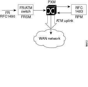
Frame over ATM Example
In this example, the FRSM-8T1 is in slot 18 of the MGX 8850, while the RPM is in slot 12.
Frame Relay router (connected to line 1 of FRSM) configuration example:
interface Serial0
ip address 192.168.101.2 255.255.255.0
encapsulation frame-relay IETF
***
FRSM configuration (See FRSM documentation for complete command syntax):
Step 1 ![]() Configure the line.
Configure the line.
SQureshi.1.18.FRSM.a> addln 1
Step 2 ![]() Configure a Frame Relay port on the line, with StrataLMI signalling.
Configure a Frame Relay port on the line, with StrataLMI signalling.
SQureshi.1.18.FRSM.a> addport 1 1 2 1 24 1
SQureshi.1.18.FRSM.a> xcnfport -pt 1 -sig 3
Step 3 ![]() Configure a service-interworking or network-interworking channel from the port to the RPM. Connect each DLCI on the port to a unique VCI on the RPM, using VPI 0.
Configure a service-interworking or network-interworking channel from the port to the RPM. Connect each DLCI on the port to a unique VCI on the RPM, using VPI 0.
SQureshi.1.18.FRSM.a> addcon 1 212 1536000 3 2 1 2 SQureshi.12.1.0.101
***
RPM configuration example:
interface Switch12/1.101 multipoint
ip address 192.168.101.12 255.255.255.0
atm pvc 101 0 101 aal5snap inarp
!
rpmrscprtn par 100 100 0 255 0 3840 4047
addcon vcc Switch 12/1.101 101 rslot 18 1 0 212 master local
***
To verify connectivity:
RPM --
rpm_slot12#ping 192.168.101.2
Type escape sequence to abort.
Sending 5, 100-byte ICMP Echos to 192.168.101.2, timeout is 2 seconds:
!!!!!
Success rate is 100 percent (5/5), round-trip min/avg/max = 4/5/8 ms
rpm_slot12#sh arp
Protocol Address Age (min) Hardware Addr Type Interface
Internet 192.168.101.2 0 0 / 101 ATM Switch12/1.101
rpm_slot12#
Frame Relay router --
rpm7206_2#show frame-relay map
Serial5/0 (up):ip 192.168.101.12 dlci 212(0xD4,0x3440), dynamic,
broadcast,
IETF, BW = 1536000, status defined, active
rpm7206_2#ping 192.168.101.12
Type escape sequence to abort.
Sending 5, 100-byte ICMP Echos to 192.168.101.12, timeout is 2 seconds:
!!!!!
Success rate is 100 percent (5/5), round-trip min/avg/max = 4/4/8 ms
rpm7206_2#
FRSM --
SQureshi.1.18.FRSM.a > dspchans
DLCI Chan EQ I/EQDepth I/EQDEThre I/EECNThre Fst/ DE Type Alarm
------------- ---- -- ----- ----- ----- ----- ----- ----- --- --- ----- -----
18.1.1.212 121 2 65535/65535 32767/32767 6553/6553 Dis/Dis SIW-X No
Number of channels: 1
ChanNumNextAvailable: 26
Syntax :dspchans
SQureshi.1.18.FRSM.a > dspports
Port Ena/Speed EQServ SignalType T391 T392 N391 N392 N393 Type
Alarm
ELMI
Ratio
-------- --- ----- ------ ------------ ---- ---- ---- ---- ---- --------
-----
----
18.1.1 Add/1536k 1 StrataLMI 10 15 6 3 4 frameRel No
Off
Number of ports: 1
PortDs0UsedLine1: 0x00ffffff
PortDs0UsedLine2: 0x00000000
PortDs0UsedLine3: 0x00000000
PortDs0UsedLine4: 0x00000000
PortDs0UsedLine5: 0x00000000
PortDs0UsedLine6: 0x00000000
PortDs0UsedLine7: 0x00000000
PortDs0UsedLine8: 0x00000000
PortNumNextAvailable: 83
Syntax :dspports
SQureshi.1.18.FRSM.a > dsplns
Line Conn Type Status/Coding Length XmtClock Alarm Stats
Type Source Alarm
---- ----- ------------ ------ -------- ------------- -------- ----- -----
18.1 RJ-48 dsx1ESF Ena/dsx1B8ZS 0-131 ft LocalTim No No
18.2 RJ-48 dsx1ESF Dis/dsx1B8ZS 0-131 ft LocalTim
18.3 RJ-48 dsx1ESF Dis/dsx1B8ZS 0-131 ft LocalTim
18.4 RJ-48 dsx1ESF Dis/dsx1B8ZS 0-131 ft LocalTim
18.5 RJ-48 dsx1ESF Dis/dsx1B8ZS 0-131 ft LocalTim
18.6 RJ-48 dsx1ESF Dis/dsx1B8ZS 0-131 ft LocalTim
18.7 RJ-48 dsx1ESF Dis/dsx1B8ZS 0-131 ft LocalTim
18.8 RJ-48 dsx1ESF Dis/dsx1B8ZS 0-131 ft LocalTim
LineNumOfValidEntries:8
Syntax :dsplns
SQureshi.1.18.FRSM.a >
ATM Service
The ATM UNI Service Modules (AUSMs) provide native ATM UNI (compliant with ATM Forum v3.0, v3.1, and v4.0) interfaces at T1 and E1 speeds, with eight ports per card, providing up to
16 Mbps of bandwidth for ATM service interfaces.
Consistent with Cisco's Intelligent QoS Management features, AUSM cards support per-VC queuing on ingress and multiple class-of-service queues on egress. AUSM cards fully support continuous bit rate (CBR), variable bit rate (VBR), unspecified bit rate (UBR), and available bit rate (ABR) service classes.
The AUSM-8 cards also support ATM Forum-compliant inverse multiplexing for ATM (IMA). This capability enables multiple T1 or E1 lines to be grouped into a single high-speed ATM port. This
N x T1 and N x E1 capability fills the gap between T1/E1 and T3/E3, providing bandwidth up to
12 Mbps (N x T1) or 16 Mbps (N x E1) without requiring a T3/E3 circuit.
A single AUSM card can provide hot standby redundancy for all active AUSM cards of the same type in the shelf (1:N redundancy).
AUSM modules are supported by standards-based management tools, including SNMP, TFTP (for configuration and statistics collection), and a command line interface. Cisco's WAN Manager application suite also provides full graphical user interface support for connection management, and CiscoView software provides equipment management.
Table 5-2 below summarizes the key attributes of the AUSM cards:
Table 5-2 AUSM Card Specifications
Setting Up the FRSM and CESM Connections to the PXM
The following procedure may be used for configuring the FRSM and CESM connection to the PXM. The AUSM is slightly different and is in the section, "Setting Up the AUSM Connection to PXM," later in this chapter.
Step 1 ![]() Go to the PXM and login.
Go to the PXM and login.
Step 2 ![]() Then, cc to the slot where the service module is:
Then, cc to the slot where the service module is:
prompt# cc 12
Step 3 ![]() Type dsplns to see interfaces:
Type dsplns to see interfaces:
prompt# dsplns
Step 4 ![]() To establish the physical connection between the service module and the PXM, enable a line with the command addln:
To establish the physical connection between the service module and the PXM, enable a line with the command addln:
prompt# addln 2
Step 5 ![]() Display ports:
Display ports:
prompt# dspports
Step 6 ![]() Add a port:
Add a port:
prompt# addprt port_num line_num port_type
Step 7 ![]() Display ports:
Display ports:
prompt# dspports
Step 8 ![]() Choose signalling type:
Choose signalling type:
prompt# xcnfport "-pt" <PortNum) -sig (type)"
<cr>
Step 9 ![]() Now configure the logical link between the service module and the PXM by typing the command addcon:
Now configure the logical link between the service module and the PXM by typing the command addcon:
prompt# addcon "port dlci cir chan_type [CAC] [Controller_Type][mastership]
[remoteConnId]"
where parameters are:
port number — values ranging from 1-192 are accepted for T1 and 1-248 for E1
DLCI number — value ranging from 0 to 1023
committed rate — 0-1536000 bps for T1; 0-2048000 bps for E1
chan type — values 1-5:
–![]() 1=NIW
1=NIW
–![]() 2=SIW-transparent
2=SIW-transparent
–![]() 3=SIW-xlation
3=SIW-xlation
–![]() 4=FUNI
4=FUNI
–![]() 5=frForward
5=frForward
CAC — Connection Admission Control (optional); 1 = enable, 2 = disable (default)
Controller Type (Signalling) — 1:PVC (PAR) - Default , 2:SPVC (PNNI)
mastership — 1 for master, 2 for slave
Remote end Connection ID — Format :
NodeName.SlotNo.PortNo.Dlci OR
NodeName.SlotNo.PortNo.ControllerId.Dlci for FR end point OR
NodeName.SlotNo.PortNo.VPI.VCI for ATM end point.
Where controller ID can be 1(PAR),2(PNNI),3(TAG)</html>l6f
Sample CESM-PXM Configuration
CESM configuration
popeye01.1.1.CESM.a > dspcd
ModuleSlotNumber: 1
FunctionModuleState: Active
FunctionModuleType: CESM-8T1
FunctionModuleSerialNum: 786306
FunctionModuleHWRev: ab
FunctionModuleFWRev: 5.0.00_12Feb99_2
FunctionModuleResetReason: Power reset
LineModuleType: LM-RJ48-8T1
LineModuleState: Present
mibVersionNumber: 20
configChangeTypeBitMap: CardCnfChng, LineCnfChng
cardIntegratedAlarm: Clear
fab number: 28-2199-02
popeye01.1.1.CESM.a >
popeye01.1.1.CESM.a > addln
ERR : incorrect number of parameters (not enough)
Syntax : addln "line_num"
line number -- values : 1 - 8
possible errors are :
a) illegal/invalid parameters
b) line aleady exists
popeye01.1.1.CESM.a > addln 1
popeye01.1.1.CESM.a > cnfln
ERR : incorrect number of parameters (not enough)
Syntax : cnfln "line_num line_code line_len clk_src [E1-signalling]"
line number -- values : 1 - 8
line code -- 2 for B8ZS (T1),
3 for HDB3 (E1),
4 for AMI (T1/E1)
line length -- 10-15 for T1,
8 for E1 with SMB line module,
9 for E1 with RJ48 line module
clock source -- clock source : 1 for loop clock, 2 for local clock
E1 signalling -- CAS: CAS, no CRC; CAS_CRC: CAS, with CRC;
CCS: CCS, no CRC; CCS_CRC: CCS, with CRC;
CLEAR: CLEAR channel
possible errors are :
a) illegal/invalid parameters
b) line doesn't exist, use addln to add line first
c) loopback/bert is on
popeye01.1.1.CESM.a > cnfln 1 2 10 2
popeye01.1.1.CESM.a > dsplns
Line Conn Type Status/Coding Length XmtClock Alarm Stats
Type Source Alarm
---- ----- ------------ ------ -------- ------------- -------- ----- -----
1.1 RJ-48 dsx1ESF Mod/dsx1B8ZS 0-131 ft LocalTim No No
1.2 RJ-48 dsx1ESF Dis/dsx1B8ZS 0-131 ft LocalTim
1.3 RJ-48 dsx1ESF Dis/dsx1B8ZS 0-131 ft LocalTim
1.4 RJ-48 dsx1ESF Dis/dsx1B8ZS 0-131 ft LocalTim
1.5 RJ-48 dsx1ESF Dis/dsx1B8ZS 0-131 ft LocalTim
1.6 RJ-48 dsx1ESF Dis/dsx1B8ZS 0-131 ft LocalTim
1.7 RJ-48 dsx1ESF Dis/dsx1B8ZS 0-131 ft LocalTim
1.8 RJ-48 dsx1ESF Dis/dsx1B8ZS 0-131 ft LocalTim
LineNumOfValidEntries: 8
Syntax : dsplns
popeye01.1.1.CESM.a > addport
ERR : incorrect number of parameters (not enough)
Syntax : addport "port_num line_num begin_slot num_slot port_type"
port number -- values : 1-192 for T1, 1-248 for E1
line number -- values : 1 - 8
beginning slot -- beginning time slot
number of slot -- number of DS0 time slots assigned
port type -- values = 1 - 3, 1: structured 2: Unstructured
3:framingOnVcDisconnect
possible errors are :
a) illegal/invalid parameters
b) port already exists
c) line not enabled
d) line not channelized
popeye01.1.1.CESM.a > addport 1 1 1 24 1
popeye01.1.1.CESM.a > dspports
Port Ena/Speed Type
------ --- ------ --------
1.1.1 Add/1536k structur
Number of ports: 1
PortDs0UsedLine1: 0x00ffffff
PortDs0UsedLine2: 0x00000000
PortDs0UsedLine3: 0x00000000
PortDs0UsedLine4: 0x00000000
PortDs0UsedLine5: 0x00000000
PortDs0UsedLine6: 0x00000000
PortDs0UsedLine7: 0x00000000
PortDs0UsedLine8: 0x00000000
PortNumNextAvailable: 10
Syntax : dspports
popeye01.1.1.CESM.a > addcon
ERR : incorrect number of parameters (not enough)
Syntax : addcon "port_num sig_type partial_fill cond_data cond_signalling
[controller_type [mastership [remoteConnId]]]"
port number -- values : 1-192 for T1, 1-248 for E1
sig_type -- values : 1 - basic, 2 - e1Cas, 3 - ds1SfCas,
4 - ds1EsfCas ;
partialfill -- values : 0 for fully filled, 20 - 47 for E1 Struct,
25 - 47 for T1 Struct, 33 - 47 for T1/E1 Unstruct ;
conddata -- values : always 255 for UDT, 0 - 255 for SDT;
condsig -- values : 0 - 15;
controller type -- 1: PVC/PAR (default), 2: SPVC/PNNI
mastership -- 1: master, 2: slave (default)
remote end connection ID -- Format : NodeName.SlotNo.PortNo.Vpi.Vci
possible errors are :
a) Illegal/Invalid parameters.
b) Channel already exists.
c) Port may not be up.
popeye01.1.1.CESM.a > addcon 1 1 47 255 0 1 2 popeye01.0.1.10.100
Note ![]() Remote SlotNo. = 0 (zero) this points to the active PXM.
Remote SlotNo. = 0 (zero) this points to the active PXM.
Sample FRSM-PXM Configuration
FRSM configuration
popeye01.1.2.FRSM.a > dspcd
ModuleSlotNumber: 2
FunctionModuleState: Active
FunctionModuleType: FRSM-8T1
FunctionModuleSerialNum: 788039
FunctionModuleHWRev: ab
FunctionModuleFWRev: 5.0.00_04Feb99_2_CIR
FunctionModuleResetReason: Reset by ASC from Cell Bus
LineModuleType: LM-RJ48-8T1
LineModuleState: Present
mibVersionNumber: 20
configChangeTypeBitMap: CardCnfChng, LineCnfChng
cardIntegratedAlarm: Clear
fab number: 28-2069-02
popeye01.1.2.FRSM.a >
popeye01.1.2.FRSM.a > addln
ERR : incorrect number of parameters (not enough)
Syntax : addln "line_num"
line number -- values ranging from 1-8 are accepted, for FRSM_8
possible errors are :
a) illegal/invalid parameters
b) line aleady exists
popeye01.1.2.FRSM.a > addln 1
popeye01.1.2.FRSM.a > cnfln
ERR : incorrect number of parameters (not enough)
Syntax : cnfln "line_num line_code line_len clk_src [E1-signalling]"
line number -- values ranging from 1-8 are accepted, for FRSM_8
line code -- 2 for B8ZS (T1),
3 for HDB3 (E1),
4 for AMI (T1/E1)
line length -- 10-15 for T1,
8 for E1 with SMB line module,
9 for E1 with RJ48 line module
clock source -- clock source : 1 for loop clock, 2 for local clock
E1 signalling -- CAS: CAS, no CRC; CAS_CRC: CAS, with CRC;
CCS: CCS, no CRC; CCS_CRC: CCS, with CRC
CLEAR : Clear E1
possible errors are :
a) illegal/invalid parameters
b) line doesn't exist, use addln to add line first
c) loopback/bert is on
popeye01.1.2.FRSM.a > cnfln 1 2 10 2
popeye01.1.2.FRSM.a > dsplns
Line Conn Type Status/Coding Length XmtClock Alarm Stats
Type Source Alarm
---- ----- ------------ ------ -------- ------------- -------- ----- -----
2.1 RJ-48 dsx1ESF Mod/dsx1B8ZS 0-131 ft LocalTim No No
2.2 RJ-48 dsx1ESF Dis/dsx1B8ZS 0-131 ft LocalTim
2.3 RJ-48 dsx1ESF Dis/dsx1B8ZS 0-131 ft LocalTim
2.4 RJ-48 dsx1ESF Dis/dsx1B8ZS 0-131 ft LocalTim
2.5 RJ-48 dsx1ESF Dis/dsx1B8ZS 0-131 ft LocalTim
2.6 RJ-48 dsx1ESF Dis/dsx1B8ZS 0-131 ft LocalTim
2.7 RJ-48 dsx1ESF Dis/dsx1B8ZS 0-131 ft LocalTim
2.8 RJ-48 dsx1ESF Dis/dsx1B8ZS 0-131 ft LocalTim
LineNumOfValidEntries: 8
Syntax : dsplns
popeye01.1.2.FRSM.a > addport
ERR : incorrect number of parameters (not enough)
Syntax : addport "port_num line_num ds0_speed begin_slot num_slot port_type"
port number -- values ranging from 1-192 are accepted for T1 and 1-248
for E1
line number -- value ranging from 1 to 8
DS0 speed -- 1 for 56K, 2 for 64K
beginning slot -- beginning time slot in 1 base
number of slot -- number of DS0 time slots assigned to
port type -- values 1-3, 1=frame relay, 2=FUNI mode-1a, 3=frForward
possible errors are :
a) illegal/invalid parameters
b) port already exists
c) line not enabled
d) line not channelized
popeye01.1.2.FRSM.a > addport 1 1 2 1 2 1
popeye01.1.2.FRSM.a > upport
ERR : incorrect number of parameters (not enough)
Syntax : upport "port_num "
port number -- values ranging from 1-192 are accepted for T1 and 1-248
for E1
possible errors are :
a) illegal/invalid parameter for port number
sprint01.1.2.FRSM.a > upport 1
popeye01.1.2.FRSM.a > dspports
Port Ena/Speed EQServ SignalType T391 T392 N391 N392 N393 Type Alarm ELMI
Ratio
-------- --- ----- ------ ------------ ---- ---- ---- ---- ---- -------- ----- ----
2.1.1 Mod/ 128k 1 NoSignalling 10 15 6 3 4 frameRel No Off
Number of ports: 1
PortDs0UsedLine1: 0x00000003
PortDs0UsedLine2: 0x00000000
PortDs0UsedLine3: 0x00000000
PortDs0UsedLine4: 0x00000000
PortDs0UsedLine5: 0x00000000
PortDs0UsedLine6: 0x00000000
PortDs0UsedLine7: 0x00000000
PortDs0UsedLine8: 0x00000000
PortNumNextAvailable: 19
Syntax : dspports
popeye01.1.2.FRSM.a > addcon
ERR : incorrect number of parameters (not enough)
Syntax : addcon "port dlci cir chan_type [CAC][Controller_Type][mastership]
[remoteConnId]"
port number -- values ranging from 1-192 are accepted for T1 and 1-248
for E1
DLCI number -- value ranging from 0 to 1023
committed rate -- 0-1536000 bps for T1; 0-2048000 bps for E1
chan type -- values 1-5, 1=NIW 2=SIW-transparent 3=SIW-xlation 4=FUNI 5
=frForward
CAC -- Connection Admission Control (optional); 1 = enable, 2 = disable
(default)
Controller Type (Signalling) -- 1: PVC (PAR) - Default , 2: SPVC (PNNI)
mastership -- 1 for master, 2 for slave
Remote end Connection ID -- Format :
NodeName.SlotNo.PortNo.Dlci OR
NodeName.SlotNo.PortNo.ControllerId.Dlci for FR end point OR
NodeName.SlotNo.PortNo.VPI.VCI for ATM end point.
Where controller ID can be 1(PAR),2(PNNI),3(TAG)
possible errors are :
a) Illegal/Invalid parameters
b) channel already exists
c) port may not be up
popeye01.1.2.FRSM.a > addcon 1 100 128000 2 2 1 2 popeye01.0.1.0.100
Note ![]() SlotNo. = 0 (zero) for the active PXM.
SlotNo. = 0 (zero) for the active PXM.
Setting Up the AUSM Connection to PXM
Use the following procedure to establish an ATM UNI/NNI connection using the AUSM card. The connection is between a T1 or E1 ATM UNI on the AUSM card and an ATM service interface elsewhere in the IPX/BPX network.
Step 1 ![]() Login to the AUSM card.
Login to the AUSM card.
Step 2 ![]() To add the line, type addln:
To add the line, type addln:
RPM-3 (configure)# addlin <line # (between 1 and 8)>
Step 3 ![]() Type cnfln for line code, line length, and clock source.
Type cnfln for line code, line length, and clock source.
Step 4 ![]() Type upport specifying the port to be upped.
Type upport specifying the port to be upped.
Step 5 ![]() Use cnfportq to set up egress queues,
Use cnfportq to set up egress queues,
where parameters are:
•![]() Port number (1-8)
Port number (1-8)
•![]() Queue number (1-16)
Queue number (1-16)
•![]() Queue priority
Queue priority
0 = disable queue
1 = high priority, always serve
2 = best available
3 = Min. guaranteed bandwidth
4 = Min. guaranteed bandwidth with max. rate shaping
5 = CBR with smoothing
•![]() Service sequence number (1-16)
Service sequence number (1-16)
•![]() Max. queue depth (1-8000)
Max. queue depth (1-8000)
•![]() CLP low threshold (1-8000)
CLP low threshold (1-8000)
•![]() CLP high threshold (1-8000)
CLP high threshold (1-8000)
•![]() EFCI threshold (1-8000)
EFCI threshold (1-8000)
Step 6 ![]() Type addcon to add the connection,
Type addcon to add the connection,
where parameters are:
•![]() Logical Connection (LCN 16-271)
Logical Connection (LCN 16-271)
•![]() Connection Type (1 = vpc, 2 = vcc)
Connection Type (1 = vpc, 2 = vcc)
•![]() Port Number (1-4)
Port Number (1-4)
•![]() VPI (0-255)
VPI (0-255)
•![]() VCI (0-65535)
VCI (0-65535)
•![]() Service Type (1 = cbr, 2 = vbr, 3 = abr)
Service Type (1 = cbr, 2 = vbr, 3 = abr)
•![]() Queue Number (1-16)
Queue Number (1-16)
Step 7 ![]() To configure UPC, use one of the following:
To configure UPC, use one of the following:
cnfupc cbr
cnfupc vbr
cnfupc abr
Step 8 ![]() Type cnfchanfst to configure ForeSight.
Type cnfchanfst to configure ForeSight.
Step 9 ![]() If queue depths need to be changed, type cnfchanq.
If queue depths need to be changed, type cnfchanq.
To add IMA ports use addimagrp.
Sample AUSM-PXM Configuration
AUSM configuration
popeye01.1.3.AUSMB8.a > dspcd
ModuleSlotNumber: 3
FunctionModuleState: Active
FunctionModuleType: AUSMB-8T1
FunctionModuleSerialNum: 023113
FunctionModuleHWRev: aa
FunctionModuleFWRev: 10.0.00_12Feb99_1
FunctionModuleResetReason: Reset by ASC from Cell Bus
LineModuleType: LM-RJ48-8T1
LineModuleState: Present
mibVersionNumber: 20
configChangeTypeBitMap: CardCnfChng, LineCnfChng
cardIntegratedAlarm: Major
cardMajorAlarmBitMap: Line Alarm
cardMinorAlarmBitMap: Channel failure
fab number: 28-2580-01
popeye01.1.3.AUSMB8.a > addln
ERR : incorrect number of parameters (not enough)
Syntax : addln "line_num"
line number -- values ranging from 1-8 are accepted, for AUSM-8T1/8E1,
IMATM-T3T1/E3E1
possible errors are :
a) illegal/invalid parameters
b) line aleady exists
popeye01.1.3.AUSMB8.a > addln 1
popeye01.1.3.AUSMB8.a > cnfln 1
ERR : incorrect number of parameters (not enough)
Syntax : cnfln "line_num line_code line_len clk_src [E1-signalling]"
line number -- values ranging from 1-8 are accepted, for AUSM-8T1/8E1,
IMATM-T3T1/E3E1
line code -- 2 for B8ZS (T1),
3 for HDB3 (E1)
line length -- 10-15 for T1, 8 for E1 with SMB module,
9 for E1 with RJ48 line module
clock source -- clock source : 1 for loop clock, 2 for local clock
E1 signalling -- CCS: CCS, no CRC; CCS_CRC: CCS, with CRC;
CLEAR: Clear E1
possible errors are :
a) illegal/invalid parameters
b) line doesn't exist, use addln to add line first
c) loopback/bert is on
popeye01.1.3.AUSMB8.a > cnfln 1 2 10 2
popeye01.1.3.AUSMB8.a > dsplns
Line Conn Type Status/Coding Length XmtClock Alarm Stats
Type Source Alarm
---- ----- ------------ ------ -------- ------------- -------- ----- -----
3.1 RJ-48 dsx1ESF Mod/dsx1B8ZS 0-131 ft LocalTim Yes No
3.2 RJ-48 dsx1ESF Dis/dsx1B8ZS 0-131 ft LocalTim
3.3 RJ-48 dsx1ESF Dis/dsx1B8ZS 0-131 ft LocalTim
3.4 RJ-48 dsx1ESF Dis/dsx1B8ZS 0-131 ft LocalTim
3.5 RJ-48 dsx1ESF Dis/dsx1B8ZS 0-131 ft LocalTim
3.6 RJ-48 dsx1ESF Dis/dsx1B8ZS 0-131 ft LocalTim
3.7 RJ-48 dsx1ESF Dis/dsx1B8ZS 0-131 ft LocalTim
3.8 RJ-48 dsx1ESF Dis/dsx1B8ZS 0-131 ft LocalTim
LineNumOfValidEntries: 8
Syntax : dsplns
popeye01.1.3.AUSMB8.a > addport
ERR : incorrect number of parameters (not enough)
Syntax : addport "port_num port_type line_num"
port number -- values ranging from 1-8
Port Type -- 1 - UNI, 2 - NNI
line number -- value ranging from 1 to 8
possible errors are :
a) Incorrect parameters
b) Line not present
c) Line part of another IMA port or ATM port
d) Port already in use
popeye01.1.3.AUSMB8.a > addport 1 1 1
popeye01.1.3.AUSMB8.a > dspports
List of ATM ports:
==================
Port PortType Line# Portenable Speed PortState
---- -------- ----- ---------- ----- ---------
3.1 UNI 1 UP 3622 Active
No IMA ports are currently active
Syntax : dspports
popeye01.1.3.AUSMB8.a > addcon
ERR : incorrect number of parameters (not enough)
Syntax : addcon "port_num vpi vci conn_type service_type [Controller_Type] [mast
ership] [remoteConnId]"
port number -- values ranging from 1-8
Channel VPI -- Virtual Path Identifier: 0 - 255
Channel VCI -- Virtual Channel Identifier: 0 - 65535 for VCC, * for VPC
Connection Type -- Connection Type : 0 - VCC , non zero - Local
VP Id of the VPC (1 to 20)
Service Type -- Service Type: 1 - CBR, 2 - VBR, 3 - ABR, 4 - UBR
Controller Type (Signalling) -- 1: PVC (PAR) - Default , 2: SPVC (PNNI)
Mastership -- 1 for master, 2 for slave Default:Slave
Remote end Connection ID -- Format : NodeName.SlotNo.PortNo.ExternalConnId
possible errors are :
a) Illegal/Invalid parameters
b) channel already exists
c) port may not be up
popeye01.1.3.AUSMB8.a > addcon 1 20 200 0 2 1 2 popeye01.0.1.20.200
Local Connection Id is : popeye01.3.1.20.200
Note ![]() This adds the AUSM connection to the active PXM.
This adds the AUSM connection to the active PXM.
Note ![]() Again, SlotNo. = 0 (zero) for the active PXM.
Again, SlotNo. = 0 (zero) for the active PXM.
Viewing FRSM, CESM and AUSM Connections Through the PXM
The following are CLI commands on the PXM, to see FRSM, CESM and AUSM connections through PXM. Whether, these are Feeder, UNI or DAX connections, the PXM command dspcons shows, all connections on the shelf. You can also, execute some commands on the service module, side to see the connection parameters (these are dspchan, dspcon etc.).
Here is a typical output of dspcons on PXM:
This End Node Name Other End Status
1.1.0.16 NODENAME 2.1.10.16 OK
1.1.0.17 NODENAME 2.1.10.17 OK
1.1.0.18 NODENAME 2.1.10.18 OK
1.1.0.19 NODENAME 2.1.10.19 OK
1.1.0.20 NODENAME 2.1.10.20 OK
1.1.0.21 NODENAME 2.1.10.21 OK
1.1.0.22 NODENAME 2.1.10.22 OK
1.1.0.23 NODENAME 2.1.10.23 OK
1.1.0.24 NODENAME 2.1.10.24 OK
1.1.0.25 NODENAME 2.1.10.25 OK
1.1.0.26 NODENAME 2.1.10.26 OK
1.1.0.27 NODENAME 2.1.10.27 OK
1.1.0.28 NODENAME 2.1.10.28 OK
1.1.0.29 NODENAME 2.1.10.29 OK
1.1.0.30 NODENAME 2.1.10.30 OK
1.1.0.31 NODENAME 2.1.10.31 OK
1.1.0.32 NODENAME 2.1.10.32 OK
Configuration Examples
ATM Configuration Examples
For detailed configuration examples, refer to the router software publications listed in the first paragraph in the Preface at the beginning of this document. The following sections contain examples of ATM interface configurations:
•![]() Example of PVCs with AAL5 and LLC/SNAP Encapsulation
Example of PVCs with AAL5 and LLC/SNAP Encapsulation
•![]() Example of PVCs in a Fully Meshed Network
Example of PVCs in a Fully Meshed Network
For examples of emulated LAN configurations, refer to the document, MGX 8850 Wide Area Switch Installation and Configuration.
Example of PVCs with AAL5 and LLC/SNAP Encapsulation
The following example creates PVC 5 on the ATM interface 5/1 using LLC/SNAP encapsulation over AAL5. ATM interface 5/1 (IP address 1.1.1.2 255.255.255.0) connects with the ATM interface (IP address 1.1.1.1 255.255.255.0) at the other end of the connection. The static map list named atm1 declares that the next node is a broadcast point for multicast packets from IP.
interface switch 5/1
ip address 1.1.1.2 255.255.255.0
map-group atm1
atm pvc 2 0 1 aal5snap
!
no ip classless
!
map-list atm1
ip 1.1.1.1 atm-vc 2 broadcast
The following example is of a typical ATM configuration for a PVC:
interface switch 5/1
ip address 131.108.168.112 255.255.255.0
map-group atm
atm pvc 2 2 2 aal5snap
atm pvc 6 6 6 aal5snap
atm pvc 7 7 7 aal5snap
clns router iso-igrp comet
!
router iso-igrp comet
net 47.0004.0001.0000.0c00.6666.00
!
router igrp 109
network 131.108.0.0
!
ip domain-name CISCO.COM
!
map-list atm
ip 131.108.168.110 atm-vc 7 broadcast
clns 47.0004.0001.0000.0c00.6e26.00 atm-vc 6 broadcast
atm-vc 2 broadcast
Example of PVCs in a Fully Meshed Network
The configurations for RPMs A, B, and C follow. In this example, the RPMs are configured to use PVCs. Fully meshed indicates that each network node has either a physical circuit or a virtual circuit connecting it to every other network node. Note that the two map-list statements configured in RPM A identify the ATM addresses of RPMs B and C. The two map-list statements in RPM B identify the ATM addresses of RPMs A and C. The two map list statements in RPM C identify the ATM addresses of RPMs A and B. Figure 5-4 illustrates a fully meshed network.
Figure 5-4 Fully Meshed ATM Configuration Example
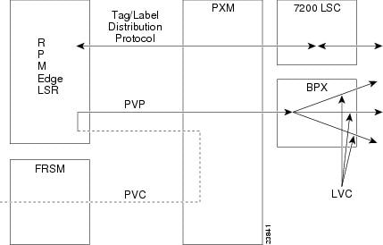
Note ![]() In the following example, RPM A, RPM B, and RPM C are located in the same MGX 8850 chassis.
In the following example, RPM A, RPM B, and RPM C are located in the same MGX 8850 chassis.
RPM A (slot 4)
ip routing
!
interface Switch 4/1
ip address 131.108.168.1 255.255.255.0
atm pvc 10 0 10 aal5snap
atm pvc 2 0 20 aal5snap
map-group test-a
!
map-list test-a
ip 131.108.168.2 atm-vc 10 broadcast
ip 131.108.168.3 atm-vc 2 broadcast
!
rpmrscprtn PAR 100 100 1 255 0 3840 4047
addcon vpc sw4/1 10 rname rslot 5 1 0 20
addcon vpc sw4/1 2 rname rslot 3 1 0 21
RPM B (slot 5)
ip routing
!
interface Switch 5/1
ip address 131.108.168.2 255.255.255.0
atm pvc 10 0 20 aal5snap
atm pvc 2 0 21 aal5snap
map-group test-b
!
map-list test-b
ip 131.108.168.1 atm-vc 10 broadcast
ip 131.108.168.3 atm-vc 2 broadcast
!
rpmrscprtn PAR 100 100 1 255 0 3840 4047
addcon vpc sw5/1 20 rname rslot 4 1 0 10 master local
addcon vpc sw5/1 21 rname rslot 3 1 0 22
RPM C (slot 3)
ip routing
!
interface Switch 3/1
ip address 131.108.168.3 255.255.255.0
atm pvc 2 0 21 aal5snap
atm pvc 4 0 22 aal5snap
map-group test-c
!
map-list test-c
ip 131.108.168.1 atm-vc 2 broadcast
ip 131.108.168.2 atm-vc 4 broadcast
!
rpmrscprtn PAR 100 100 1 255 0 3840 4047
addcon vpc sw3/1 21 rname rslot 4 1 0 20 master local
addcon vpc sw3/1 22 rname rslot 5 1 0 21 master local
Configuration Mode
You can configure the RPM manually if you prefer not to use AutoInstall or the prompt-driven System Configuration Dialog.
Note ![]() Refer to the section "Cisco IOS Software Basics" later in this chapter for basic information about Cisco IOS software, getting context-sensitive help, and saving configuration changes.
Refer to the section "Cisco IOS Software Basics" later in this chapter for basic information about Cisco IOS software, getting context-sensitive help, and saving configuration changes.
Take the following steps to configure the RPM manually:
Step 1 ![]() Connect a console terminal to the RPM.
Connect a console terminal to the RPM.
Follow the instructions described in "Installing the Cisco MGX 8850 RPM," and then power ON the RPM.
Step 2 ![]() When you are prompted to enter the initial dialog, enter no to go into the normal operating mode of the RPM:
When you are prompted to enter the initial dialog, enter no to go into the normal operating mode of the RPM:
Would you like to enter the initial dialog? [yes]: no
Step 3 ![]() After a few seconds you will see the user EXEC prompt (Router>).
After a few seconds you will see the user EXEC prompt (Router>).
By default, the host name is Router, but the prompt will match the current host name. In the following examples, the host name is MGX8850-RPM. Enter the enable command to enter enable mode. You can only make configuration changes in enable mode:
MGX8850-RPM> enable
The prompt will change to the privileged EXEC (enable) prompt, MGX8850-RPM#.
Step 4 ![]() Enter the configure terminal command at the enable prompt to enter configuration mode:
Enter the configure terminal command at the enable prompt to enter configuration mode:
MGX8850-RPM# config terminal
You can now enter any changes you want to the configuration. You will probably want to perform the following tasks:
a. ![]() Assign a host name for the RPM using the hostname command.
Assign a host name for the RPM using the hostname command.
b. ![]() Enter an enable secret using the enable secret command.
Enter an enable secret using the enable secret command.
c. ![]() Enter an enable password using the enable password command.
Enter an enable password using the enable password command.
d. ![]() Assign addresses to the interfaces using the protocol address command.
Assign addresses to the interfaces using the protocol address command.
e. ![]() Specify which protocols to support on the interfaces.
Specify which protocols to support on the interfaces.
Refer to the Cisco IOS configuration and command reference publications for more information about the commands you can use to configure the RPM. You can also refer to the MGX 8850 Wide Area Switch Command Reference and MGX 8850 Wide Area Switch Installation and Configuration documents for information about the commands you can use to configure the RPM.
Step 5 ![]() When you finish configuring the RPM, enter the exit command until you return to the privileged EXEC prompt (MGX8850-RPM#).
When you finish configuring the RPM, enter the exit command until you return to the privileged EXEC prompt (MGX8850-RPM#).
Step 6 ![]() To save the configuration changes to NVRAM, enter the copy running-config startup-config command at the privileged EXEC prompt:
To save the configuration changes to NVRAM, enter the copy running-config startup-config command at the privileged EXEC prompt:
MGX8850-RPM# copy running-config startup-config
********
The RPM is now configured and will boot with the configuration you entered.
This concludes the initial RPM configuration.
Verifying Network Connectivity
When you have installed and configured the RPM, you can use the following commands in user EXEC mode to verify network connectivity:
•![]() ping—Sends a special datagram to the destination device, then waits for a reply datagram from that device
ping—Sends a special datagram to the destination device, then waits for a reply datagram from that device
•![]() telnet—Logs in to a remote node
telnet—Logs in to a remote node
•![]() trace—Discovers the routes that packets take when traveling from one RPM to another
trace—Discovers the routes that packets take when traveling from one RPM to another
If there is a problem with network connectivity, refer to "Maintaining the Cisco MGX 8850 RPM," and check the cable connections. If there is still a problem, check the RPM configuration. Contact customer service for further assistance.
Specifying the Boot Method
You can enter multiple boot commands in the configuration in NVRAM to provide a backup method for loading the Cisco IOS image onto the RPM. The RPM boots using the first boot command that succeeds. If you enter multiple boot commands, the RPM executes them in the order they are entered. There are two ways to load the Cisco IOS image: from the PXM hard drive or from a TFTP server on the network.
1. ![]() PXM Hard Drive
PXM Hard Drive
Information stored in HD is not vulnerable to network failures that might occur when you load system software from servers. In the following example, replace filename with the filename of the Cisco IOS image:
MGX8850-RPM> enable
Password: enablepassword
MGX8850-RPM# configure terminal
MGX8850-RPM (config)# boot system c:filename
MGX8850-RPM (config)# Ctrl-Z
MGX8850-RPM# copy running-config startup-config
Building configuration ...
[OK]
MGX8850-RPM# exit
MGX8850-RPM>
2. ![]() TFTP server
TFTP server
If the PXM hard drive does not contain a valid Cisco IOS image, you can specify that system software be loaded from a TFTP server on your network as a backup boot method for the RPM. In the following example, replace filename with the filename of the Cisco IOS image, and replace ipaddress with the IP address of the TFTP server:
MGX8850-RPM> enable
Password: enablepassword
MGX8850-RPM# configure terminal
MGX8850-RPM (config)# boot system tftp filename ipaddress
MGX8850-RPM (config)# Ctrl-Z
MGX8850-RPM# copy running-config startup-config
Building configuration ...
[OK]
MGX8850-RPM# exit
MGX8850-RPM>
3. ![]() PXM C: drive
PXM C: drive
The RPM has access to the file system on the PXM C:drive, in the C:RPM directory. Use the Console port on the RPM to boot the RPM from Flash so that you configure its ATM switch interface as no shutdown. This then lets you access the c: drive on the PXM and copy files to the startup config or to bootflash.
In the following example, replace filename with the filename of the Cisco IOS image. Type the following commands to boot the RPM from the PXM and copy files:
MGX8850-RPM> enable
Password:enablepassword
MGX8850-RPM# configure terminal
MGX8850-RPM (config)# boot system c:filename
MGX8850-RPM (config)# Ctrl-Z
MGX8850-RPM# copy running-config startup-config
Building configuration ...
[OK]
MGX8850-RPM#
*****
Then reload the RPM to get back to rommon and then boot full IOS from the PXM disk.
Note ![]() Put the RPM IOS image in the RPM directory of the PXM hard disk with the filename specified in the RPM boot command.
Put the RPM IOS image in the RPM directory of the PXM hard disk with the filename specified in the RPM boot command.
Cisco IOS Software Basics
This section provides you with some basic information about the Cisco IOS software and includes the following sections:
•![]() Getting Context-Sensitive Help
Getting Context-Sensitive Help
Cisco IOS Modes of Operation
Cisco IOS software provides access to several different command modes. Each command mode provides a different group of related commands.
For security purposes, Cisco IOS software provides two levels of access to commands: user and privileged. The unprivileged user mode is called user EXEC mode. The privileged mode is called privileged EXEC mode and requires a password. The commands available in user EXEC mode are a subset of the commands available in privileged EXEC mode.
Table 5-3 describes some of the most commonly used modes, how to enter the modes, and the resulting prompts. The prompt helps you identify which mode you are in and, therefore, which commands are available to you.
Table 5-3 Cisco IOS Operating Modes
|
|
|
|
|
|---|---|---|---|
User EXEC |
User EXEC commands allow you to connect to remote devices, change terminal settings on a temporary basis, perform basic tests, and list system information. The EXEC commands available at the user level are a subset of those available at the privileged level. |
Log in. |
MGX8850-RPM> |
Privileged EXEC |
Privileged EXEC commands set operating parameters. The privileged command set includes those commands contained in user EXEC mode, and also the configure command through which you can access the remaining command modes. Privileged EXEC mode also includes high-level testing commands, such as debug. |
From user EXEC mode, enter the enable EXEC command. |
MGX8850-RPM# |
Global configuration |
Global configuration commands apply to features that affect the system as a whole. |
From global configuration mode, enter the configure privileged EXEC command. |
MGX8850-RPM(config)# |
Interface configuration |
Interface configuration commands modify the operation of an interface such as an Ethernet or serial port. Many features are enabled on a per-interface basis. Interface configuration commands always follow an interface global configuration command, which defines the interface type. |
From global configuration mode, enter the interface type number command. For example, enter the interface int switch 9/1 command to configure the ATM interface. |
MGX8850-RPM(config-if)# |
ROM monitor |
ROM monitor commands are used to perform low- |
From privileged EXEC mode, enter the reload EXEC command. Press Break during the first 60 seconds while the system is booting. |
> |
1 You can modify the configuration register value using the config-reg configuration command. Refer to "Maintaining the Cisco MGX 8850 RPM," for more information. |
Almost every configuration command also has a no form. In general, use the no form to disable a feature or function. Use the command without the keyword no to reenable a disabled feature or to enable a feature that is disabled by default. For example, IP routing is enabled by default. To disable IP routing, enter the no ip routing command and enter ip routing to reenable it. The Cisco IOS software command reference publication provides the complete syntax for the configuration commands and describes what the no form of a command does.
Getting Context-Sensitive Help
In any command mode, you can get a list of available commands by entering a question mark (?).
MGX8850-RPM> ?
To obtain a list of commands that begin with a particular character sequence, type in those characters followed immediately by the question mark (?). Do not include a space. This form of help is called word help, because it completes a word for you.
MGX8850-RPM# co?
configure connect copy
To list keywords or arguments, enter a question mark in place of a keyword or argument. Include a space before the question mark. This form of help is called command syntax help, because it reminds you which keywords or arguments are applicable based on the command, keywords, and arguments you have already entered.
MGX8850-RPM# configure ?
memory Configure from NV memory
network Configure from a TFTP network host
terminal Configure from the terminal
<cr>
You can also abbreviate commands and keywords by entering just enough characters to make the command unique from other commands. For example, you can abbreviate the show command to sh.
Saving Configuration Changes
Whenever you make changes to the RPM configuration, you must save the changes to memory so they will not be lost if there is a system reload or power outage. There are two types of configuration files: the running (current operating) configuration and the startup configuration. The running configuration is stored in RAM; the startup configuration is stored in NVRAM.
To display the current running configuration, enter the show running-config command. Enter the copy running-config startup-config command to save the current running configuration to the startup configuration file in NVRAM.
MGX8850-RPM> enable
MGX8850-RPM# copy running-config startup-config
To display the startup configuration, enter the show startup-config command. Enter the copy startup-config running-config command to write the startup configuration to the running configuration.
MGX8850-RPM> enable
MGX8850-RPM# copy startup-config running-config
To erase both configuration files (and start over), enter the write erase and reload commands:
MGX8850-RPM> enable
MGX8850-RPM# write erase
MGX8850-RPM# reload

Warning ![]() This command sequence will erase the entire RPM configuration in RAM and NVRAM and reload the RPM.
This command sequence will erase the entire RPM configuration in RAM and NVRAM and reload the RPM.
 Feedback