- action
- alarm-contact
- archive download-sw
- archive tar
- archive upload-sw
- bandwidth
- boot config-file
- boot helper
- boot helper-config-file
- boot manual
- boot private-config-file
- boot system
- channel-group
- channel-protocol
- class
- class-map
- clear ipc
- clear lacp
- clear logging onboard
- clear mac address-table
- clear pagp
- clear rep counters
- clear spanning-tree counters
- conform-action
- controller BITS input applique
- controller BITS output applique
- controller BITS shutdown
- copy logging onboard module
- define interface-range
- delete
- deny (MAC access-list configuration)
- diagnostic schedule test
- diagnostic start test
- duplex
- errdisable detect cause
- errdisable recovery
- ethernet evc
- ethernet lmi
- ethernet oam remote-failure
- ethernet uni id
- exceed-action
- flowcontrol
- hw-module module logging onboard
- interface port-channel
- interface range
- interface vlan
- ip access-group
- ip address
- ip igmp filter
- ip igmp max-groups
- ip igmp profile
- ip igmp snooping
- ip igmp snooping last-member-query-interval
- ip igmp snooping report-suppression
- ip igmp snooping tcn
- ip igmp snooping tcn flood
- ip igmp snooping vlan immediate-leave
- ip igmp snooping vlan mrouter
- ip igmp snooping vlan static
- ip ssh
- l2protocol
- lacp port-priority
- lacp system-priority
- location (global configuration)
- location (interface configuration)
- logging event
- logging file
- mac access-group
- mac access-list extended
- mac address-table aging-time
- mac address-table learning
- mac address-table move update
- mac address-table notification
- mac address-table static
- macro apply
- macro description
- macro global
- macro global description
- match (access-map configuration)
- match access-group
- match cos
- match discard-class
- match ip dscp
- match ip precedence
- match mpls experimental topmost
- match qos-group
- match vlan
- mdix auto
- mtu
- network-clock hold-off
- network-clock input-source
- network-clock revertive
- network-clock synchronization ssm option
- network-clock wait-to-restore
- network-clock-select
- network-clock-select hold-off timeout
- network-clock-select hold-timeout
- network-clock-select mode
- network-clock-select option
- network-clock-select output
- network-clock-select wait-to-restore-timeout
- oam protocol cfm svlan
- pagp learn-method
- pagp port-priority
- permit (MAC access-list configuration)
- police
- policy-map
- port-channel load-balance
- port-type
- priority
- ql-enabled rep-segment
- queue-limit
- random-detect
- random-detect cos
- random-detect cos-based
- random-detect dscp
- random-detect exponential-weighting-constant
- random-detect precedence
- rep admin vlan
- rep block port
- rep lsl-age-timer
- rep preempt delay
- rep preempt segment
- rep segment
- rep stcn
- reserved-only
Cisco ME 3800X and ME 3600X Switch
Cisco IOS Commands
action
To set the action for the VLAN access map entry, use the action command in access-map configuration mode. To set the action to the default value, which is to forward, use the no form of this command.
action {drop | forward}
no action
Syntax Description
drop |
Drops the packet when the specified conditions are matched. |
forward |
Forwards the packet when the specified conditions are matched. |
Defaults
The default action is to forward packets.
Command Modes
Access-map configuration
Command History
|
|
|
|---|---|
12.2(52)EY |
This command was introduced. |
Usage Guidelines
You enter access-map configuration mode by using the vlan access-map global configuration command.
If the action is drop, you should define the access map, including configuring any access control list (ACL) names in match clauses, before applying the map to a VLAN, or all packets could be dropped.
In access-map configuration mode, use the match access-map configuration command to define the match conditions for a VLAN map. Use the action command to set the action that occurs when a packet matches the conditions.
The drop and forward parameters are not used in the no form of the command.
You can verify your settings by entering the show vlan access-map privileged EXEC command.
Examples
This example shows how to identify and apply a VLAN access map vmap4 to VLANs 5 and 6 that causes the VLAN to forward an IP packet if the packet matches the conditions defined in access list al2:
Switch(config)# vlan access-map vmap4
Switch(config-access-map)# match ip address al2
Switch(config-access-map)# action forward
Switch(config-access-map)# exit
Switch(config)# vlan filter vmap4 vlan-list 5-6
Related Commands
alarm-contact
To configure triggers and severity levels for external alarms, use the alarm-contact command in global configuration mode. To remove the configuration, use the no form of this command.
alarm-contact {contact-number {description string | severity {critical | major | minor} | trigger {closed | open}} | all {severity {critical | major | minor} | trigger {closed | open}}
no alarm-contact {contact-number {description | severity | trigger} | all {severity | trigger}
Defaults
No alarms are configured.
Command Modes
Global configuration
Command History
|
|
|
|---|---|
12.2(52)EY |
This command was introduced. |
Usage Guidelines
The no alarm-contact contact-number description sets the description to an empty string.
The no alarm-contact {contact-number | all} severity sets the alarm-contact severity to minor.
The no alarm-contact {contact-number | all} trigger sets the external alarm-contact trigger to closed.
You can verify your settings by entering the show env alarm-contact or the show running-config privileged EXEC command.
Examples
This example shows how to configure alarm contact number 1 to report a critical alarm when the contact is open.
Switch(config)# alarm-contact 1 description main_lab_door
Switch(config)# alarm-contact 1 severity critical
Switch(config)# alarm-contact 1 trigger open
Dec  4 10:34:09.049: %PLATFORM_ENV-1-EXTERNAL_ALARM_CONTACT_ASSERT: Alarm asserted:
main_lab_door
Switch# show env alarm-contact
ALARM CONTACT 1
Status: asserted
Description: main_lab_door
Severity: critical
Trigger: open
This example shows how to configure clear alarm contact number 1 and the show command outputs.
Switch(config)# no alarm-contact 1 description
Dec  4 10:39:33.621: %PLATFORM_ENV-1-EXTERNAL_ALARM_CONTACT_CLEAR: Alarm cleared:
main_lab_door Dec  4 10:39:33.621: %PLATFORM_ENV-1-EXTERNAL_ALARM_CONTACT_ASSERT: Alarm
asserted: external alarm contact 1
Switch(config)# no alarm-contact 1 severity
Dec  4 10:39:46.774: %PLATFORM_ENV-1-EXTERNAL_ALARM_CONTACT_CLEAR: Alarm cleared: external
alarm contact 1 Dec  4 10:39:46.774: %PLATFORM_ENV-1-EXTERNAL_ALARM_CONTACT_ASSERT: Alarm
asserted: external alarm contact 1
Switch(config)# no alarm-contact 1 trigger open
Dec  4 10:39:56.547: %PLATFORM_ENV-1-EXTERNAL_ALARM_CONTACT_CLEAR: Alarm cleared: external
alarm contact 1
Switch(config)# end
Switch# show env alarm-contact
ALARM CONTACT 1
Status: not asserted
Description: external alarm contact 1
Severity: minor
Trigger: closed
ALARM CONTACT 2
Status: not asserted
Description: external alarm contact 2
Severity: minor
Trigger: closed
ALARM CONTACT 3
Status: not asserted
Description: external alarm contact 3
Severity: minor
Trigger: closed
ALARM CONTACT 4
Status: not asserted
Description: external alarm contact 4
Severity: minor
Trigger: closed
Related Commands
|
|
|
|---|---|
show env alarm-contact |
Displays the alarm setting and status for the switch. |
archive download-sw
To download a new image from a TFTP server to the switch and to overwrite or keep the existing image, use the archive download-sw command in privileged EXEC mode.
archive download-sw {/force-reload | /imageonly | /leave-old-sw | /no-set-boot | /no-version-check | /overwrite | /reload | /safe} source-url
Syntax Description
Defaults
The current software image is not overwritten with the downloaded image.
Both the software image and HTML files are downloaded.
The new image is downloaded to the flash: file system.
The BOOT environment variable is changed to point to the new software image on the flash: file system.
Image names are case sensitive; the image file is provided in tar format.
Compatibility of the version on the image to be downloaded is checked.
Command Modes
Privileged EXEC
Command History
|
|
|
|---|---|
12.2(52)EY |
This command was introduced. |
Usage Guidelines
The /imageonly option removes the HTML files for the existing image if the existing image is being removed or replaced. Only the Cisco IOS image (without the HTML files) is downloaded.
Using the /safe or /leave-old-sw option can cause the new image download to fail if there is insufficient flash memory. If leaving the software in place prevents the new image from fitting in flash memory due to space constraints, an error results.
If you used the /leave-old-sw option and did not overwrite the old image when you downloaded the new one, you can remove the old image by using the delete privileged EXEC command. For more information, see the delete command.

Note ![]() Use the /no-version-check option with care. This option allows an image to be downloaded without first confirming that it is not incompatible with the switch.
Use the /no-version-check option with care. This option allows an image to be downloaded without first confirming that it is not incompatible with the switch.
Use the /overwrite option to overwrite the image on the flash device with the downloaded one.
If you specify the command without the /overwrite option, the download algorithm verifies that the new image is not the same as the one on the switch flash device. If the images are the same, the download does not occur. If the images are different, the old image is deleted, and the new one is downloaded.
After downloading a new image, enter the reload privileged EXEC command to begin using the new image, or specify the /reload or /force-reload option in the archive download-sw command.
Examples
This example shows how to download a new image from a TFTP server at 172.20.129.10 and overwrite the image on the switch:
Switch# archive download-sw /overwrite tftp://172.20.129.10/test-image.tar
This example shows how to download only the software image from a TFTP server at 172.20.129.10 to the switch:
Switch# archive download-sw /imageonly tftp://172.20.129.10/test-image.tar
This example shows how to keep the old software version after a successful download:
Switch# archive download-sw /leave-old-sw tftp://172.20.129.10/test-image.tar
Related Commands
archive tar
To create a tar file, list files in a tar file, or extract the files from a tar file, use the archive tar command in privileged EXEC mode.
archive tar {/create destination-url flash:/file-url} | {/table source-url} | {/xtract source-url flash:/file-url [dir/file...]}
Syntax Description
Defaults
None
Command Modes
Privileged EXEC
Command History
|
|
|
|---|---|
12.2(52)EY |
This command was introduced. |
Usage Guidelines
Filenames and directory names are case sensitive.
Image names are case sensitive.
Examples
This example shows how to create a tar file. The command writes the contents of the new-configs directory on the local flash device to a file named saved.tar on the TFTP server at 172.20.10.30:
Switch# archive tar /create tftp:172.20.10.30/saved.tar flash:/new-configs
This example shows how to display the contents of the file that is in flash memory. The contents of the tar file appear on the screen:
Switch# archive tar /table flash:image_name-mz.122-release.tar
info (219 bytes)
image_name-mz.122-release/(directory)
image_name-mz.122-release(610856 bytes)
image_name-mz.122-release/info (219 bytes)
info.ver (219 bytes)
This example shows how to display only the html directory and its contents:
Switch# archive tar /table flash:image_name-mz.122-release.tar
image_name-mz.122-release/html
image_name-mz.122-release/html/ (directory)
image_name-mz.122-release/html/const.htm (556 bytes)
image_name-mz.122-release/html/xhome.htm (9373 bytes)
image_name-mz.122-release/html/menu.css (1654 bytes)
<output truncated>
This example shows how to extract the contents of a tar file on the TFTP server at 172.20.10.30. This command extracts just the new-configs directory into the root directory on the local flash file system. The remaining files in the saved.tar file are ignored.
Switch# archive tar /xtract tftp://172.20.10.30/saved.tar flash:/ new-configs
Related Commands
|
|
|
|---|---|
archive download-sw |
Downloads a new image from a TFTP server to the switch. |
archive upload-sw |
Uploads an existing image on the switch to a server. |
archive upload-sw
To upload an existing switch image to a server, use the archive upload-sw command in privileged EXEC mode.
archive upload-sw [/version version_string] destination-url
Syntax Description
Defaults
Uploads the currently running image from the flash: file system.
Command Modes
Privileged EXEC
Command History
|
|
|
|---|---|
12.2(52)EY |
This command was introduced. |
Usage Guidelines
Use the upload feature only if the HTML files associated with the embedded device manager have been installed with the existing image.
The files are uploaded in this sequence: the Cisco IOS image, the HTML files, and info. After these files are uploaded, the software creates the tar file.
Image names are case sensitive.
Examples
This example shows how to upload the currently running image to a TFTP server at 172.20.140.2:
Switch# archive upload-sw tftp://172.20.140.2/test-image.tar
Related Commands
|
|
|
|---|---|
archive download-sw |
Downloads a new image to the switch. |
archive tar |
Creates a tar file, lists the files in a tar file, or extracts the files from a tar file. |
bandwidth
To configure class-based weighted fair queuing (CBWFQ) by setting the output bandwidth for a policy-map class, use the bandwidth command in policy-map class configuration mode. To remove the bandwidth setting for the class, use the no form of this command.
bandwidth {rate | percent value | remaining percent value}
no bandwidth [rate | percent value | remaining percent value]
Syntax Description
Defaults
No bandwidth is defined.
Command Modes
Policy-map class configuration
Command History
|
|
|
|---|---|
12.2(52)EY |
This command was introduced. |
Usage Guidelines
You use the bandwidth policy-map class command to control output traffic. The bandwidth command specifies the bandwidth for traffic in that class. CBWFQ derives the weight for packets belonging to the class from the bandwidth allocated to the class and uses the weight to ensure that the queue for that class is serviced fairly. Bandwidth settings are not supported in input policy maps.
•![]() Configuring bandwidth for a class of traffic as an absolute rate (kilobits per second) or a percentage of total bandwidth represents the minimum bandwidth guarantee (CIR) for that traffic class.
Configuring bandwidth for a class of traffic as an absolute rate (kilobits per second) or a percentage of total bandwidth represents the minimum bandwidth guarantee (CIR) for that traffic class.
•![]() You cannot configure bandwidth as an absolute rate or a percentage of total bandwidth when priority is configured for another class in the output policy. However, you can configure CIR, PIR, and EIR bandwidth independently for a class so can use the bandwidth, bandwidth remaining, and shape average commands at the same time within a class.
You cannot configure bandwidth as an absolute rate or a percentage of total bandwidth when priority is configured for another class in the output policy. However, you can configure CIR, PIR, and EIR bandwidth independently for a class so can use the bandwidth, bandwidth remaining, and shape average commands at the same time within a class.
•![]() Configuring bandwidth as a percentage of remaining bandwidth determines the portion of the excess bandwidth of the target that is allocated to the class. This means that the class is allocated bandwidth only if there is excess bandwidth on the target, and if there is no minimum bandwidth guarantee for this traffic class. By default the total excess bandwidth is divided equally among the classes.
Configuring bandwidth as a percentage of remaining bandwidth determines the portion of the excess bandwidth of the target that is allocated to the class. This means that the class is allocated bandwidth only if there is excess bandwidth on the target, and if there is no minimum bandwidth guarantee for this traffic class. By default the total excess bandwidth is divided equally among the classes.
•![]() You cannot configure bandwidth as percentage of remaining bandwidth when priority is configured for another class in the output policy map.
You cannot configure bandwidth as percentage of remaining bandwidth when priority is configured for another class in the output policy map.
When you configure bandwidth in an output policy, you must specify the same units in each bandwidth configuration; that is, all absolute values (rates) or percentages.
You can verify your settings by entering the show policy-map privileged EXEC command.
Examples
This example shows how to allocate 25 percent of the total available bandwidth to the traffic class defined by the class map:
Switch(config)# policy-map gold_policy
Switch(config-pmap)# class out_class-1
Switch(config-pmap-c)# bandwidth percent 25
Switch(config-pmap-c)# exit
Switch(config-pmap)# exit
Switch(config)# interface gigabitethernet0/1
Switch(config-if)# service-policy output gold_policy
Switch(config-if)# exit
This example shows how to set the precedence of output queues by setting bandwidth in kilobits per second. The classes outclass1, outclass2, and outclass3 and class-default get a minimum of 40000, 20000, 10000, and 10000 kb/s. Any excess bandwidth is divided among the classes in the same proportion as the CIR rate.
Switch(config)# policy-map out-policy
Switch(config-pmap)# class outclass1
Switch(config-pmap-c)# bandwidth 40000
Switch(config-pmap-c)# exit
Switch(config-pmap)# class outclass2
Switch(config-pmap-c)# bandwidth 20000
Switch(config-pmap-c)# exit
Switch(config-pmap)# class outclass3
Switch(config-pmap-c)# bandwidth 10000
Switch(config-pmap-c)# exit
Switch(config-pmap)# class class-default
Switch(config-pmap-c)# bandwidth 10000
Switch(config-pmap-c)# exit
Switch(config-pmap)# exit
Switch(config)# interface gigabitethernet 0/1
Switch(config-if)# service-policy output out-policy
Switch(config-if)# exit
This example shows how to allocate the excess bandwidth among queues by configuring bandwidth for a traffic class as a percentage of remaining bandwidth. The class outclass1 is given priority queue treatment. The other classes are configured to get percentages of the excess bandwidth if any remains after servicing the priority queue: outclass2 is configured to get 50 percent, outclass3 to get 20 percent, and the class class-default to get the remaining 30 percent.
Switch(config)# policy-map out-policy
Switch(config-pmap)# class outclass1
Switch(config-pmap-c)# priority
Switch(config-pmap-c)# exit
Switch(config-pmap)# class outclass2
Switch(config-pmap-c)# bandwidth remaining percent 50
Switch(config-pmap-c)# exit
Switch(config-pmap)# class outclass3
Switch(config-pmap-c)# bandwidth remaining percent 20
Switch(config-pmap-c)# exit
Switch(config-pmap)# exit
Switch(config)# interface gigabitethernet 0/1
Switch(config-if)# service-policy output out-policy
Switch(config-if)# exit
Related Commands
boot config-file
To specify the filename that Cisco IOS uses to read and write a nonvolatile copy of the system configuration, use the boot config-file command in global configuration mode. To return to the default setting, use the no form of this command.
boot config-file file-name
no boot config-file
Syntax Description
file-name |
The name of the configuration file. |
Defaults
The default configuration file is flash:config.text.
Command Modes
Global configuration
Command History
|
|
|
|---|---|
12.2(52)EY |
This command was introduced. |
Usage Guidelines
Filenames and directory names are case sensitive.
This command changes the setting of the CONFIG_FILE environment variable. For more information, see "Cisco ME 3800X and ME 3600X Switch Boot Loader Commands."
Related Commands
|
|
|
|---|---|
show boot |
Displays the settings of the boot environment variables. |
boot helper
To dynamically load files during boot loader initialization to extend or patch the functionality of the boot loader, use the boot helper command in global configuration mode. To return to the default, use the no form of this command.
boot helper filesystem:/file-url ...
no boot helper
Syntax Description
Defaults
No helper files are loaded.
Command Modes
Global configuration
Command History
|
|
|
|---|---|
12.2(52)EY |
This command was introduced. |
Usage Guidelines
This variable is used only for internal development and testing.
Filenames and directory names are case sensitive.
This command changes the setting of the HELPER environment variable. For more information, see "Cisco ME 3800X and ME 3600X Switch Boot Loader Commands."
Related Commands
|
|
|
|---|---|
show boot |
Displays the settings of the boot environment variables. |
boot helper-config-file
To specify the name of the configuration file to be used by the Cisco IOS helper image, use the boot helper-config-file command in global configuration mode. If this is not set, the file specified by the CONFIG_FILE environment variable is used by all versions of Cisco IOS that are loaded. To return to the default setting, use the no form of this command.
boot helper-config-file filename
no boot helper-config file
Syntax Description
file-name |
The helper configuration file to load. |
Defaults
No helper configuration file is specified.
Command Modes
Global configuration
Command History
|
|
|
|---|---|
12.2(52)EY |
This command was introduced. |
Usage Guidelines
This variable is used only for internal development and testing.
Filenames and directory names are case sensitive.
This command changes the setting of the HELPER_CONFIG_FILE environment variable. For more information, see "Cisco ME 3800X and ME 3600X Switch Boot Loader Commands."
Related Commands
|
|
|
|---|---|
show boot |
Displays the settings of the boot environment variables. |
boot manual
To enable manually booting the switch during the next boot cycle, use the boot manual command in global configuration mode. To return to the default setting, use the no form of this command.
boot manual
no boot manual
Syntax Description
This command has no arguments or keywords.
Defaults
Manual booting is disabled.
Command Modes
Global configuration
Command History
|
|
|
|---|---|
12.2(52)EY |
This command was introduced. |
Usage Guidelines
The next time you reboot the system, the switch is in boot loader mode, which is shown by the switch: prompt. To boot the system, use the boot boot loader command, and specify the name of the bootable image.
This command changes the setting of the MANUAL_BOOT environment variable. For more information, see "Cisco ME 3800X and ME 3600X Switch Boot Loader Commands."
Related Commands
|
|
|
|---|---|
show boot |
Displays the settings of the boot environment variables. |
boot private-config-file
To specify the filename that Cisco IOS uses to read and write a nonvolatile copy of the private configuration, use the boot private-config-file command in global configuration mode. To return to the default setting, use the no form of this command.
boot private-config-file filename
no boot private-config-file
Syntax Description
filename |
The name of the private configuration file. |
Defaults
The default configuration file is private-config.
Command Modes
Global configuration
Command History
|
|
|
|---|---|
12.2(52)EY |
This command was introduced. |
Usage Guidelines
Filenames are case sensitive.
Examples
This example shows how to specify the name of the private configuration file to be pconfig:
Switch(config)# boot private-config-file pconfig
Related Commands
|
|
|
|---|---|
show boot |
Displays the settings of the boot environment variables. |
boot system
To specify the Cisco IOS image to load during the next boot cycle, use the boot system command in global configuration mode. To return to the default setting, use the no form of this command.
boot system filesystem:/file-url ...
no boot system
Syntax Description
filesystem: |
Alias for a flash file system. Use flash: for the system board flash device. |
/file-url |
The path (directory) and name of a bootable image. Separate image names with a semicolon. |
Defaults
The switch attempts to automatically boot the system by using information in the BOOT environment variable. If this variable is not set, the switch attempts to load and execute the first executable image it can by performing a recursive, depth-first search throughout the flash file system. In a depth-first search of a directory, each encountered subdirectory is completely searched before continuing the search in the original directory.
Command Modes
Global configuration
Command History
|
|
|
|---|---|
12.2(52)EY |
This command was introduced. |
Usage Guidelines
Filenames and directory names are case sensitive.
If you are using the archive download-sw privileged EXEC command to maintain system images, you never need to use the boot system command. The boot system command is automatically manipulated to load the downloaded image.
This command changes the setting of the BOOT environment variable. For more information, see "Cisco ME 3800X and ME 3600X Switch Boot Loader Commands."
Related Commands
|
|
|
|---|---|
show boot |
Displays the settings of the boot environment variables. |
channel-group
To assign an Ethernet port to an EtherChannel group, use the channel-group command in interface configuration mode. To remove an Ethernet port from an EtherChannel group, use the no form of this command.
channel-group channel-group-number mode {active | auto [non-silent] | desirable [non-silent] | on | passive}
no channel-group
PAgP modes:
channel-group channel-group-number mode {auto [non-silent] | desirable [non-silent]}
LACP modes:
channel-group channel-group-number mode {active | passive}
On mode:
channel-group channel-group-number mode on
Syntax Description
Defaults
No channel groups are assigned.
No mode is configured.
Command Modes
Interface configuration
Command History
|
|
|
|---|---|
12.2(52)EY |
This command was introduced. |
Usage Guidelines
For Layer 2 EtherChannels, you do not have to create a port-channel interface first by using the interface port-channel global configuration command before assigning a physical port to a channel group. Instead, you can use the channel-group interface configuration command. It automatically creates the port-channel interface when the channel group gets its first physical port if the logical interface is not already created. If you create the port-channel interface first, the channel-group-number can be the same as the port-channel-number, or you can use a new number. If you use a new number, the channel-group command dynamically creates a new port channel.
If the port is a UNI or an ENI, you must use the no shutdown interface configuration command to enable it before using the channel-group command. UNIs and ENIs are disabled by default. NNIs are enabled by default.
You do not have to disable the IP address that is assigned to a physical port that is part of a channel group, but we strongly recommend that you do so.
You create Layer 3 port channels by using the interface port-channel command followed by the no switchport interface configuration command. You should manually configure the port-channel logical interface before putting the interface into the channel group.
After you configure an EtherChannel, configuration changes that you make on the port-channel interface apply to all the physical ports assigned to the port-channel interface. Configuration changes applied to the physical port affect only the port where you apply the configuration. To change the parameters of all ports in an EtherChannel, apply configuration commands to the port-channel interface, for example, spanning-tree commands or commands to configure a Layer 2 EtherChannel as a trunk.
If you do not specify non-silent with the auto or desirable mode, silent is assumed. The silent mode is used when the switch is connected to a device that is not PAgP-capable and seldom, if ever, sends packets. A example of a silent partner is a file server or a packet analyzer that is not generating traffic. In this case, running PAgP on a physical port prevents that port from ever becoming operational. However, it allows PAgP to operate, to attach the port to a channel group, and to use the port for transmission. Both ends of the link cannot be set to silent.
In the on mode, an EtherChannel exists only when a port group in the on mode is connected to another port group in the on mode.

Do not configure an EtherChannel in both the PAgP and LACP modes. EtherChannel groups running PAgP and LACP can coexist on the same switch. Individual EtherChannel groups can run either PAgP or LACP, but they cannot interoperate.
If you set the protocol by using the channel-protocol interface configuration command, the setting is not overridden by the channel-group interface configuration command.
For a complete list of configuration guidelines, see the "Configuring EtherChannels" chapter in the software configuration guide for this release.
You can verify your settings by entering the show running-config privileged EXEC command.
Examples
This example shows how to configure an EtherChannel. It assigns two static-access ports in VLAN 10 to channel 5 with the PAgP mode desirable:
Switch# configure terminal
Switch(config)# interface range gigabitethernet0/1 -2
Switch(config-if-range)# switchport mode access
Switch(config-if-range)# switchport access vlan 10
Switch(config-if-range)# channel-group 5 mode desirable
Switch(config-if-range)# end
This example shows how to configure an EtherChannel. It assigns two static-access ports in VLAN 10 to channel 5 with the LACP mode active:
Switch# configure terminal
Switch(config)# interface range gigabitethernet0/1 -2
Switch(config-if-range)# switchport mode access
Switch(config-if-range)# switchport access vlan 10
Switch(config-if-range)# channel-group 5 mode active
Switch(config-if-range)# end
Related Commands
channel-protocol
To restrict the protocol used on a port to manage channeling, use the channel-protocol command in interface configuration mode. To return to the default setting, use the no form of this command.
channel-protocol {lacp | pagp}
no channel-protocol
Syntax Description
lacp |
Configures an EtherChannel with the Link Aggregation Control Protocol (LACP). |
pagp |
Configures an EtherChannel with the Port Aggregation Protocol (PAgP). |
Defaults
No protocol is assigned to the EtherChannel.
Command Modes
Interface configuration
Command History
|
|
|
|---|---|
12.2(52)EY |
This command was introduced. |
Usage Guidelines
Use the channel-protocol command only to restrict a channel to LACP or PAgP. If you set the protocol by using the channel-protocol command, the setting is not overridden by the channel-group interface configuration command.
You must use the channel-group interface configuration command to configure the EtherChannel parameters. The channel-group command also can set the mode for the EtherChannel.
You cannot enable both the PAgP and LACP modes on an EtherChannel group.
PAgP and LACP are not compatible; both ends of a channel must use the same protocol.
You can verify your settings by entering the show etherchannel [channel-group-number] protocol privileged EXEC command.
Examples
This example shows how to specify LACP as the protocol that manages the EtherChannel:
Switch(config-if)# channel-protocol lacp
Related Commands
|
|
|
|---|---|
channel-group |
Assigns an Ethernet port to an EtherChannel group. |
show etherchannel protocol |
Displays protocol information the EtherChannel. |
class
To specify the name of the class whose policy you want to create or to change or to specify the system default class before you configure a policy and to enter policy-map class configuration mode, use the class command in policy-map configuration mode. To remove the class from a policy map, use the no form of this command.
class {class-map-name| class-default}
no class {class-map-name| class-default}
Syntax Description
Defaults
No policy map classes are defined.
Command Modes
Policy-map configuration
Command History
|
|
|
|---|---|
12.252)EY |
This command was introduced. |
Usage Guidelines
Before using the class class-map-name command in policy-map configuration mode, you must create the class by using the class-map class-map-name global configuration command. The class class-default is the class to which traffic is directed if that traffic does not match any of the match criteria in the configured class maps.
Use the policy-map global configuration command to identify the policy map and to enter policy-map configuration mode. After specifying a policy map, you can configure a policy for new classes or modify a policy for any existing classes in that policy map.
You attach the policy map to a port by using the service-policy interface configuration command.
After entering the class command, you enter policy-map class configuration mode, and these configuration commands are available:
•![]() bandwidth: specifies the bandwidth allocated for a class belonging to a policy map. For more information, see the bandwidth command.
bandwidth: specifies the bandwidth allocated for a class belonging to a policy map. For more information, see the bandwidth command.
•![]() exit: exits policy-map class configuration mode and returns to policy-map configuration mode.
exit: exits policy-map class configuration mode and returns to policy-map configuration mode.
•![]() no: returns a command to its default setting.
no: returns a command to its default setting.
•![]() police: defines an individual policer for the classified traffic. The policer specifies the bandwidth limitations and the action to take when the limits are exceeded. For more information, see the police and policy-map class commands.
police: defines an individual policer for the classified traffic. The policer specifies the bandwidth limitations and the action to take when the limits are exceeded. For more information, see the police and policy-map class commands.
•![]() priority: sets the strict scheduling priority for this class or, when used with the police keyword, sets priority with police. For more information, see the priority policy-map class command.
priority: sets the strict scheduling priority for this class or, when used with the police keyword, sets priority with police. For more information, see the priority policy-map class command.
•![]() queue-limit: sets the queue maximum threshold for Weighted Tail Drop (WTD). For more information, see the queue-limit command.
queue-limit: sets the queue maximum threshold for Weighted Tail Drop (WTD). For more information, see the queue-limit command.
•![]() service-policy: configures a QoS service policy to attach to a parent policy map for an input or output policy. For more information, see the set cos command.
service-policy: configures a QoS service policy to attach to a parent policy map for an input or output policy. For more information, see the set cos command.
•![]() set: specifies a value to be assigned to the classified traffic. For more information, see the set commands.
set: specifies a value to be assigned to the classified traffic. For more information, see the set commands.
•![]() shape average: specifies the average traffic shaping rate. For more information, see the shape average command.
shape average: specifies the average traffic shaping rate. For more information, see the shape average command.
To return to policy-map configuration mode, use the exit command. To return to privileged EXEC mode, use the end command.
You can verify your settings by entering the show policy-map privileged EXEC command.
Examples
This example shows how to create a policy map called policy1, define a class class1, and enter policy-map class configuration mode to set a criterion for the class.
Switch(config)# policy-map policy1
Switch(config-pmap)# class class1
Switch(config-pmap-c)# set dscp 10
Switch(config-pmap-c)# exit
Related Commands
class-map
To create a class map to be used for matching packets to a specified criteria and to enter class-map configuration mode, use the class-map command in global configuration mode. To delete an existing class map, use the no form of this command.
class-map [match-all | match-any] class-map-name
no class-map [match-all | match-any] class-map-name
Syntax Description
Defaults
No class maps are defined.
If neither the match-all or the match-any keyword is specified, the default is match-all.
Command Modes
Global configuration
Command History
|
|
|
|---|---|
12.2(52)EY |
This command was introduced. |
Usage Guidelines
Use this command to specify the name of the class for which you want to create or to modify class-map match criteria and to enter class-map configuration mode.
The switch supports a maximum of 4000 unique class maps.
You use the class-map command and class-map configuration mode to define packet classification as part of a globally named service policy applied on a per-port basis. When you configure a class map, you can use one or more match commands to specify match criteria. Packets arriving at either the input or output interface (determined by how you configure the service-policy interface configuration command) are checked against the class-map match criteria to determine if the packet belongs to that class.
A match-all class map means that the packet must match all entries and can have no other match statements. The match-all keyword is supported only for outer VLAN and inner VLAN, or outer CoS and inner CoS matches for 802.1Q tunneling (QinQ) packets. The match-all keyword is rejected for all other mutually exclusive match criteria.
After you are in class-map configuration mode, these configuration commands are available:
•![]() description: describes the class map (up to 200 characters). The show class-map privileged EXEC command displays the description and the name of the class map.
description: describes the class map (up to 200 characters). The show class-map privileged EXEC command displays the description and the name of the class map.
•![]() exit: exits QoS class-map configuration mode.
exit: exits QoS class-map configuration mode.
•![]() match: configures classification criteria. For more information, see the match class-map configuration commands.
match: configures classification criteria. For more information, see the match class-map configuration commands.
•![]() no: removes a match statement from a class map.
no: removes a match statement from a class map.
You can verify your settings by entering the show class-map privileged EXEC command.
Examples
This example shows how to configure the class map called class1. By default, the class map is match-all and therefore can contain no other match criteria.
Switch(config)# class-map class1
Switch(config-cmap)# exit
This example shows how to configure a match-any class map with one match criterion, which is an access list called 103. This class map (matching an ACL) is supported only in an input policy map.
Switch(config)# class-map class2
Switch(config-cmap)# match access-group 103
Switch(config-cmap)# exit
This example shows how to delete the class map class1:
Switch(config)# no class-map class1
Related Commands
clear ipc
To clear Interprocess Communications Protocol (IPC) statistics, use the clear ipc command in privileged EXEC mode.
clear ipc {queue-statistics | statistics}
Syntax Description
queue-statistics |
Clears the IPC queue statistics. |
statistics |
Clears the IPC statistics. |
Defaults
No default is defined.
Command Modes
Privileged EXEC
Command History
|
|
|
|---|---|
12.2(52)EY |
This command was introduced. |
Usage Guidelines
You can clear all statistics by using the clear ipc statistics command, or you can clear only the queue statistics by using the clear ipc queue-statistics command.
You can verify that the statistics were deleted by entering the show ipc rpc or the show ipc session privileged EXEC command.
Examples
This example shows how to clear all statistics:
Switch# clear ipc statistics
This example shows how to clear only the queue statistics:
Switch# clear ipc queue-statistics
Related Commands
|
|
|
|---|---|
show ipc {rpc | session} |
Displays the IPC multicast routing statistics. |
clear lacp
To clear Link Aggregation Control Protocol (LACP) channel-group counters, use the clear lacp command in privileged EXEC mode.
clear lacp {channel-group-number counters | counters}
Syntax Description
channel-group-number |
(Optional) Channel group number. The range is 1 to 26. |
counters |
Clears traffic counters. |
Defaults
No default is defined.
Command Modes
Privileged EXEC
Command History
|
|
|
|---|---|
12.2(52)EY |
This command was introduced. |
Usage Guidelines
You can clear all counters by using the clear lacp counters command, or you can clear only the counters for the specified channel group by using the clear lacp channel-group-number counters command.
You can verify that the information was deleted by entering the show lacp counters or the show lacp 4 counters privileged EXEC command.
Examples
This example shows how to clear all channel-group information:
Switch# clear lacp counters
This example shows how to clear LACP traffic counters for group 4:
Switch# clear lacp 4 counters
Related Commands
|
|
|
|---|---|
show lacp |
Displays LACP channel-group information. |
clear logging onboard
To clear all the on-board failure logging (OBFL) data except for the uptime and CLI-command information stored in the flash memory, use the clear logging onboard command in privileged EXEC mode.
clear logging onboard [module {slot-number | all}]
Syntax Description
Defaults
No default is defined.
Command Modes
Privileged EXEC
Command History
|
|
|
|---|---|
12.2(52)EY |
This command was introduced. |
Usage Guidelines
We recommend that you keep OBFL enabled and do not clear the data stored in the flash memory.
You can verify that the information was cleared by entering the show logging onboard onboard privileged EXEC command.
Examples
These examples show how to clear all the OBFL information except for the uptime and CLI-command information:
Switch# clear logging onboard
Clear logging onboard buffer [confirm]
PID: ME-3400E-24TS-M , VID: 03 , SN: FOC1225U4CY
Switch# clear logging onboard module all
Clear logging onboard buffer [confirm]
PID: ME-3400E-24TS-M , VID: 03 , SN: FOC1225U4CY
Related Commands
|
|
|
|---|---|
hw-module module logging onboard |
Enables OBFL. |
show logging onboard |
Displays OBFL information. |
clear mac address-table
To delete a specific dynamic address from the MAC address table, all dynamic addresses on a particular interface, or all dynamic addresses on a particular VLAN, use the clear mac address-table command in privileged EXEC mode. This command also clears the MAC address notification global counters.
clear mac address-table {dynamic [address mac-addr | bridge-domain number3 | interface interface-id | vlan vlan-id] | move update | notification}
Syntax Description
Defaults
No default is defined.
Command Modes
Privileged EXEC
Command History
|
|
|
|---|---|
12.2(52)EY |
This command was introduced. |
Examples
This example shows how to remove a specific MAC address from the dynamic address table:
Switch# clear mac address-table dynamic address 0008.0070.0007
You can verify that any information was deleted by entering the show mac address-table privileged EXEC command.
This example shows how to clear the mac address-table move update related counters.
Switch# clear mac address-table move update
You can verify that the information was cleared by entering the show mac address-table move update privileged EXEC command.
Related Commands
clear pagp
To clear Port Aggregation Protocol (PAgP) channel-group information, use the clear pagp command in privileged EXEC mode.
clear pagp {channel-group-number counters | counters}
Syntax Description
channel-group-number |
(Optional) Channel group number. The range is 1 to 48. |
counters |
Clear traffic counters. |
Defaults
No default is defined.
Command Modes
Privileged EXEC
Command History
|
|
|
|---|---|
12.2(52)EY |
This command was introduced. |
Usage Guidelines
You can clear all counters by using the clear pagp counters command, or you can clear only the counters for the specified channel group by using the clear pagp channel-group-number counters command.
You can verify that information was deleted by entering the show pagp privileged EXEC command.
Examples
This example shows how to clear all channel-group information:
Switch# clear pagp counters
This example shows how to clear PAgP traffic counters for group 10:
Switch# clear pagp 10 counters
Related Commands
|
|
|
|---|---|
show pagp |
Displays PAgP channel-group information. |
clear rep counters
To clear Resilient Ethernet Protocol (REP) counters for the specified interface or all interfaces, use the clear rep counters command in privileged EXEC mode.
clear rep counters [interface interface-id]
Syntax Description
interface interface-id |
(Optional) Specifies a REP interface whose counters should be cleared. |
Defaults
No default is defined.
Command Modes
Privileged EXEC
Command History
|
|
|
|---|---|
12.2(52)EY |
This command was introduced. |
Usage Guidelines
You can clear all REP counters by using the clear rep counters command, or you can clear only the counters for the interface by using the clear rep counters interface interface-id command.
When you enter the clear rep counters command, only the counters visible in the output of the show interface rep detail command are cleared. SNMP visible counters are not cleared as they are read-only.
You can verify that REP information was deleted by entering the show interfaces rep detail privileged EXEC command.
Examples
This example shows how to clear all REP counters for all REP interfaces:
Switch# clear rep counters
Related Commands
|
|
|
|---|---|
show interfaces rep detail |
Displays detailed REP configuration and status information. |
clear spanning-tree counters
To clear the spanning-tree counters or to restart the protocol migration processor on all spanning-tree interfaces or on the specified interface, use the clear spanning-tree counters command in privileged EXEC mode.
clear spanning-tree {counters [interface interface-id] | detected-protocols [interface interface-id]}
Syntax Description
Defaults
No default is defined.
Command Modes
Privileged EXEC
Command History
|
|
|
|---|---|
12.2(52)EY |
This command was introduced. |
Usage Guidelines
If the interface-id is not specified, spanning-tree counters are cleared for all STP ports or the protocol migration is restarted on all STP ports.
A switch running the rapid per-VLAN spanning-tree plus (rapid-PVST+) protocol or the Multiple Spanning Tree Protocol (MSTP) supports a built-in protocol migration mechanism that enables it to interoperate with legacy IEEE 802.1D switches. If a rapid-PVST+ switch or an MSTP switch receives a legacy IEEE 802.1D configuration bridge protocol data unit (BPDU) with the protocol version set to 0, it sends only IEEE 802.1D BPDUs on that port. A multiple spanning-tree (MST) switch can also detect that a port is at the boundary of a region when it receives a legacy BPDU, an MST BPDU (Version 3) associated with a different region, or a rapid spanning-tree (RST) BPDU (Version 2).
However, the switch does not automatically revert to the rapid-PVST+ or the MSTP mode if it no longer receives IEEE 802.1D BPDUs. It cannot learn whether the legacy switch has been removed from the link unless the legacy switch is the designated switch. Use the clear spanning-tree detected-protocols command in this situation.
Examples
This example shows how to clear spanning-tree counters for all STP ports:
Switch# clear spanning-tree counters
This example shows how to restart the protocol migration process on a port:
Switch# clear spanning-tree detected-protocols interface gigabitethernet0/1
Related Commands
conform-action
To set actions for a policy-map class for packets that conform to the committed information rate (CIR), use the conform-action command in policy-map class police configuration mode. To cancel the action or to return to the default action, use the no form of this command.
conform-action {drop | set-cos-transmit new cos-value | set-discard-class-transmit new discard-value | set-dscp-transmit new dscp-value | set-mpls-exp-imposition-transmit new-imposition-exp-value | set-mpls-exp-topmost transmit new-topmost-exp-value | set-prec-transmit value new prec-value | set-qos-transmit value new qos-value| transmit}
no conform-action {drop | set-cos-transmit new cos-value | set-discard-class-transmit new discard-value | set-dscp-transmit new dscp-value | set-mpls-exp-imposition-transmit new-imposition-exp-value | set-mpls-exp-topmost transmit new-topmost-exp-value | set-prec-transmit value new prec-value | set-qos-transmit value new qos-value| transmit}
Syntax Description
Defaults
The default conform action is to send the packet.
Command Modes
Policy-map class police configuration
Command History
|
|
|
|---|---|
12.2(52)EY |
This command was introduced. |
Usage Guidelines
You configure conform actions for packets when the packet rate conforms to the configured conform burst.
The switch also supports simultaneously marking multiple QoS parameters for the same class and configuring conform-action, exceed-action, and violate-action marking.
Access policy-map class police configuration mode by entering the police policy-map class command. See the police policy-map class configuration command for more information.
Use this command to set one or more conform actions for a traffic class.
You can verify your settings by entering the show policy-map privileged EXEC command.
Examples
This example shows how to configure the conform action of a policy map to set a new CoS value to 3 and send the packet.
Switch(config)# class-map cos-4
Switch(config-cmap)# match cos 4
Switch(config-cmap)# exit
Switch(config)# policy-map in-policy
Switch(config-pmap)# class cos-4
Switch(config-pmap-c)# police cir 5000000 pir 8000000
Switch(config-pmap-c-police)# conform-action set-cos-transmit 3
Switch(config-pmap-c-police)# end
Related Commands
controller BITS input applique
To configure the Building Integrated Timing Supply (BITS) clock input link type and characteristics, use the controller BITS input applique command in global configuration mode. To remove the configuration, use the no form of this command.
controller BITS input applique E1{2048KHz | framing {fas_crc4 | fas_nocrc | |mfas_crc4 | mfas_nocre} linecode {ami | hdb3}
controller BITS input applique T1 framing {d4 | esf} linecode {ami | b8zs}
no controller BITS input applique
Syntax Description
Defaults
The default input timing is E1.
Command Modes
Global configuration
Command History
|
|
|
|---|---|
12.2(52)EY |
This command was introduced. |
Examples
This example shows how to set the input line type to T1 with ESF framing and B8ZS line coding:
Switch(config)# controller BITS input applique T1 framing esf linecode ami b8zs
Switch(config)# exit
Related Commands
|
|
|
|---|---|
show controller bits |
Displays BITS configuration for the switch. |
controller BITS output applique
To configure the Building Integrated Timing Supply (BITS) clock output link type and characteristics, use the controller BITS output applique command in global configuration mode. To remove the configuration, use the no form of this command.
controller BITS output applique E1{2048KHz | framing {fas_crc4 | fas_nocrc | |mfas_crc4 | mfas_nocre} linecode {ami | hdb3}
controller BITS output applique T1 framing {d4 | esf} linecode {ami | b8zs} line-build-out {0-133ft | 133-266ft | 266-399ft | 399-533ft | 533-655ft}
no controller BITS output applique
Syntax Description
Command Default
The default output timing is E1.
Command Modes
Global configuration
Command History
|
|
|
|---|---|
12.2(52)EY |
This command was introduced. |
Examples
This example shows how to set the output line type to T1 with ESF framing and B8ZS line coding and a line buildout of 0 to 133 feet:
Switch(config)# controller BITS output applique T1 framing esf linecode ami b8zs
build-out 0-133ft
Switch(config)# exit
Related Commands
|
|
|
|---|---|
show controller bits |
Displays BITS configuration for the switch. |
controller BITS shutdown
To shut down the Building Integrated Timing Supply (BITS) clock controller, use the controller BITS shutdown command in global configuration mode.To reverse the shutdown, use the no form of this command.
controller BITS shutdown
no controller BITS shutdown
Syntax Description
This command has no keywords.
Defaults
The clock controller is on by default.
Command Modes
Global configuration
Command History
|
|
|
|---|---|
12.2(52)EY |
This command was introduced. |
Examples
This example shows how to shut down the BITS controller:
Switch(config)# controller BITS shutdown
Switch(config)# exit
Related Commands
|
|
|
|---|---|
show controller bits |
Displays BITS configuration for the switch. |
copy logging onboard module
To copy on-board failure logging (OBFL) data to the local network or a specific file system, use the copy logging onboard module command in privileged EXEC mode.
copy logging onboard module [slot-number] destination
Syntax Description
Defaults
This command has no default setting.
Command Modes
Privileged EXEC
Command History
|
|
|
|---|---|
12.2(52)EY |
This command was introduced. |
Usage Guidelines
For information about OBFL, see the hw-module module logging onboard global configuration command.
Examples
This example shows how to copy the OBFL data messages to the obfl_file file on the flash file system:
Switch# copy logging onboard module flash:obfl_file
OBFL copy successful
Related Commands
|
|
|
|---|---|
hw-module module logging onboard |
Enables OBFL. |
show logging onboard |
Displays OBFL information. |
define interface-range
To create an interface-range macro, use the define interface-range command in global configuration mode. To delete the defined macro, use the no form of this command.
define interface-range macro-name interface-range
no define interface-range macro-name interface-range
Syntax Description
macro-name |
Name of the interface-range macro; up to 32 characters. |
interface-range |
Interface range; for valid values for interface ranges, see "Usage Guidelines." |
Defaults
This command has no default setting.
Command Modes
Global configuration
Command History
|
|
|
|---|---|
12.2(52)EY |
This command was introduced. |
Usage Guidelines
The macro name is a 32-character maximum character string.
A macro can contain up to five ranges.
All interfaces in a range must be the same type; that is, all Gigabit Ethernet ports, all TenGigabit Ethernet ports, all EtherChannel ports, or all VLANs, but you can combine multiple interface types in a macro.
When entering the interface-range, use this format:
•![]() type {first-interface} - {last-interface}
type {first-interface} - {last-interface}
•![]() You must add a space between the first interface number and the hyphen when entering an interface-range. For example, gigabitethernet 0/1 - 2 is a valid range; gigabitethernet 0/1-2 is not a valid range
You must add a space between the first interface number and the hyphen when entering an interface-range. For example, gigabitethernet 0/1 - 2 is a valid range; gigabitethernet 0/1-2 is not a valid range
Valid values for type and interface:
•![]() vlan vlan-id, where vlan-id is from 1 to 4094
vlan vlan-id, where vlan-id is from 1 to 4094
VLAN interfaces must have been configured with the interface vlan command (the show running-config privileged EXEC command displays the configured VLAN interfaces). VLAN interfaces not displayed by the show running-config command cannot be used in interface-ranges.
•![]() port-channel port-channel-number, where port-channel-number is from 1 to 48
port-channel port-channel-number, where port-channel-number is from 1 to 48
•![]() gigabitethernet module/{first port} - {last port}
gigabitethernet module/{first port} - {last port}
•![]() tengigabitethernet module/{first port} - {last port}
tengigabitethernet module/{first port} - {last port}
For physical interfaces:
•![]() module is always 0.
module is always 0.
•![]() the range is type 0/number - number (for example, gigabitethernet 0/1 - 2).
the range is type 0/number - number (for example, gigabitethernet 0/1 - 2).
When you define a range, you must enter a space before the hyphen (-), for example:
gigabitethernet0/1 - 2
You can also enter multiple ranges. When you define multiple ranges, you must enter a space after the first entry before the comma (,). The space after the comma is optional, for example:
gigabitethernet0/3, tengigabitethernet0/1 - 2
gigabitethernet0/3 -4, tengigabitethernet0/1 - 2
Examples
This example shows how to create a multiple-interface macro:
Switch(config)# define interface-range macro1 fastethernet0/1 - 2, gigabitethernet0/1 - 2
Related Commands
|
|
|
|---|---|
interface range |
Executes a command on multiple ports at the same time. |
show running-config |
Displays the operating configuration. |
delete
To delete a file or directory on the flash memory device, use the delete command in privileged EXEC mode.
delete [/force] [/recursive] {flash | nvram}
Syntax Description
Command Modes
Privileged EXEC
Command History
|
|
|
|---|---|
12.2(52)EY |
This command was introduced. |
Usage Guidelines
If you use the /force keyword, you are prompted once at the beginning of the deletion process to confirm the deletion.
If you use the /recursive keyword without the /force keyword, you are prompted to confirm the deletion of every file.
The prompting behavior depends on the setting of the file prompt global configuration command. By default, the switch prompts for confirmation on destructive file operations. For more information about this command, see the Cisco IOS Command Reference for Release 12.2.
Examples
This example shows how to remove the directory that contains the old software image after a successful download of a new image:
Switch# delete /force /recursive flash:/old-image
You can verify that the directory was removed by entering the dir filesystem: privileged EXEC command.
Related Commands
|
|
|
|---|---|
archive download-sw |
Downloads a new image to the switch and overwrites or keeps the existing image. |
deny (MAC access-list configuration)
To prevent non-IP traffic from being forwarded if the conditions are matched, use the deny command in MAC access-list configuration mode. To remove a deny condition from the named MAC access list, use the no form of this command.
deny {any | host src-MAC-addr | src-MAC-addr mask} {any | host dst-MAC-addr | dst-MAC-addr mask} [type mask | aarp | amber | cos cos | dec-spanning | decnet-iv | diagnostic | dsm | etype-6000 | etype-8042 | lat | lavc-sca | lsap lsap mask |mop-console | mop-dump | msdos | mumps | netbios | vines-echo | vines-ip | xns-idp]
no deny {any | host src-MAC-addr | src-MAC-addr mask} {any | host dst-MAC-addr | dst-MAC-addr mask} [type mask | aarp | amber | cos cos | dec-spanning | decnet-iv | diagnostic | dsm | etype-6000 | etype-8042 | lat | lavc-sca | lsap lsap mask | mop-console | mop-dump | msdos | mumps | netbios | vines-echo | vines-ip | xns-idp]
Syntax Description
Note ![]() Though visible in the command-line help strings, appletalk is not supported as a matching condition.
Though visible in the command-line help strings, appletalk is not supported as a matching condition.
To filter IPX traffic, you use the type mask or lsap lsap mask keywords, depending on the type of IPX encapsulation being used. Filter criteria for IPX encapsulation types as specified in Novell terminology and Cisco IOS terminology are listed in Table 2-1.
Defaults
This command has no defaults. However; the default action for a MAC-named ACL is to deny.
Command Modes
MAC-access list configuration
Command History
|
|
|
|---|---|
12.2(52)EY |
This command was introduced. |
Usage Guidelines
You enter MAC-access list configuration mode by using the mac access-list extended global configuration command.
If you use the host keyword, you cannot enter an address mask; if you do not use the host keyword, you must enter an address mask.
When an access control entry (ACE) is added to an access control list, an implied deny-any-any condition exists at the end of the list. That is, if there are no matches, the packets are denied. However, before the first ACE is added, the list permits all packets.
Note ![]() For more information about named MAC extended access lists, see the software configuration guide for this release.
For more information about named MAC extended access lists, see the software configuration guide for this release.
You can verify your settings by entering the show access-lists privileged EXEC command.
Examples
This example shows how to define the named MAC extended access list to deny NETBIOS traffic from any source to MAC address 00c0.00a0.03fa. Traffic matching this list is denied.
Switch(config-ext-macl)# deny any host 00c0.00a0.03fa netbios.
This example shows how to remove the deny condition from the named MAC extended access list:
Switch(config-ext-macl)# no deny any 00c0.00a0.03fa 0000.0000.0000 netbios.
This example denies all packets with Ethertype 0x4321:
Switch(config-ext-macl)# deny any any 0x4321 0
Related Commands
diagnostic schedule test
To configure the diagnostic test schedule, use the diagnostic schedule test command in global configuration mode. to remove the schedule, use the no form of this command.
diagnostic schedule test {name | test-id | test-id-range | all | basic} {daily hh:mm | on mm dd yyyy hh:mm | weekly day-of-week hh:mm}
no diagnostic schedule test {name | test-id | test-id-range | all | basic} {daily hh:mm | on mm dd yyyy hh:mm | weekly day-of-week hh:mm}
Syntax Description
name |
Specifies the name of the test. To display the test names in the test-ID list, enter the show diagnostic content privileged EXEC command. |
test-id |
Specifies the ID number of the test. The range is from 1 to 6. To display the test numbers in the test-ID list, enter the show diagnostic content privileged EXEC command. |
test-id-range |
Specifies more than one test with the range of test ID numbers. Enter the range as integers separated by a comma and a hyphen (for example, 1,3-6 specifies test IDs 1, 3, 4, 5, and 6). To display the test numbers in the test-ID list, enter the show diagnostic content privileged EXEC command. |
all |
Specifies all of the diagnostic tests. |
basic |
Specifies the basic on-demand diagnostic tests. |
daily hh:mm |
Specifies the daily scheduling of the diagnostic tests. hh:mm—Enter the time as a 2-digit number (for a 24-hour clock) for hours:minutes; the colon (:) is required, such as 12:30. |
on mm dd yyyy hh:mm |
Specifies the scheduling of the diagnostic tests on a specific day and time. For mm dd yyyy: • • • |
weekly day-of-week hh:mm |
Specifies the weekly scheduling of the diagnostic tests. day-of-week—Spell out the day of the week, such as Monday, Tuesday, and so on, with upper-case or lower-case characters. |
Defaults
This command has no default settings.
Command Modes
Global configuration
Command History
|
|
|
|---|---|
12.2(52)EY |
This command was introduced. |
Examples
This example shows how to schedule diagnostic testing for a specific day and time:
Switch(config)# diagnostic schedule test 1,2,4-6 on november 3 2006 23:10
This example shows how to schedule diagnostic testing to occur weekly at a specific time:
Switch(config)# diagnostic schedule test TestPortAsicMem weekly friday 09:23
Related Commands
|
|
|
|---|---|
show diagnostic |
Displays online diagnostic test results. |
diagnostic start test
To run an online diagnostic test, use the diagnostic start test command in privileged EXEC mode.
diagnostic start test {name | test-id | test-id-range | all | basic}
Syntax Description
name |
Specifies the name of the test. To display the test names in the test-ID list, enter the show diagnostic content privileged EXEC command. |
test-id |
Specifies the ID number of the test. The range is from 1 to 6. To display the test numbers in the test-ID list, enter the show diagnostic content privileged EXEC command. |
test-id-range |
Specifies more than one test with the range of test ID numbers. Enter the range as integers separated by a comma and a hyphen (for example, 1,3-6 specifies test IDs 1, 3, 4, 5, and 6). To display the test numbers in the test-ID list, enter the show diagnostic content privileged EXEC command. |
all |
Specifies all the diagnostic tests. |
basic |
Specifies the basic on-demand diagnostic tests. |
Defaults
This command has no default setting.
Command Modes
Privileged EXEC
Command History
|
|
|
|---|---|
12.2(52)EY |
This command was introduced. |
Usage Guidelines
After you start the tests by using the diagnostic start command, you cannot stop the testing process.
The switch supports these tests:
ID Test Name [On-Demand Test Attributes]
--- -------------------------------------------
1 TestPortAsicMem [B*D*R**]
2 TestPortAsicCam [B*D*R**]
3 TestPortAsicLoopback [B*D*R**]
4 TestPortLoopback [B*D*R**]
5 TestFpga [B*D*R**]
--- -------------------------------------------
To identify a test name, use the show diagnostic content privileged EXEC command to display the test ID list. To specify test 3 by using the test name, enter the diagnostic start switch number test TestPortAsicCam privileged EXEC command.
To specify more than one test, use the test-id-range parameter, and enter integers separated by a comma and a hyphen. For example, to specify tests 2, 3, and 4, enter the diagnostic start test 2-4 command. To specify tests 1, 3, 4, 5, and 6, enter the diagnostic start test 1,3-6 command.
Examples
This example shows how to start diagnostic test 1:
Switch# diagnostic start test 1
Switch#
06:27:50: %DIAG-6-TEST_RUNNING: Running TestPortAsicMem {ID=1} ...
06:27:51: %DIAG-6-TEST_OK: TestPortAsicSMem {ID=1} has completed
successfully
This example shows how to start diagnostic test 3. Running this test disrupts the normal system operation and then reloads the switch.
Switch# diagnostic start test 3
Running test(s) 3 will cause the switch under test to reload after completion of
the test list.
Running test(s) 2 may disrupt normal system operation
Do you want to continue? [no]: y
Switch#
00:00:25: %SPANTREE-5-EXTENDED_SYSID: Extended SysId enabled for type vlan
00:00:29: %SYS-5-CONFIG_I: Configured from memory by console
00:00:30: %DIAG-6-TEST_RUNNING : Running TestPortAsicLoopback{ID=2} ...
00:00:30: %DIAG-6-TEST_OK: TestPortAsicLoopback{ID=2} has completed successfully
Related Commands
|
|
|
|---|---|
show diagnostic |
Displays online diagnostic test results. |
duplex
To specify the duplex mode of operation for a port, use the duplex command in interface configuration mode. To return the port to its default value, use the no form of this command.
duplex {auto | full | half}
no duplex
Note ![]() This command is not available on 10 Gigabit Ethernet ports.
This command is not available on 10 Gigabit Ethernet ports.
Syntax Description
Defaults
The default is auto for Fast Ethernet and Gigabit Ethernet ports and for 1000BASE-T small form-factor pluggable (SFP) modules.
The default is half for 100BASE-FX MMF SFP modules.
Command Modes
Interface configuration
Command History
|
|
|
|---|---|
12.2(52)EY |
This command was introduced. |
Usage Guidelines
This command is visible for an SPP module only when a 1000BASE-T SFP module or a 100BASE-FX MMF SFP module is in the SFP module slot. All other SFP modules operate only in full-duplex mode.
•![]() When a 1000BASE-T SFP module is in the SFP module slot, you can configure duplex mode to auto or full.
When a 1000BASE-T SFP module is in the SFP module slot, you can configure duplex mode to auto or full.
•![]() When a 100BASE-FX MMF SFP module is in the SFP module slot, you can configure duplex mode to half or full. Although the auto keyword is available, it puts the interface in half-duplex mode (the default) because the 100BASE-FX MMF SFP module does not support autonegotiation.
When a 100BASE-FX MMF SFP module is in the SFP module slot, you can configure duplex mode to half or full. Although the auto keyword is available, it puts the interface in half-duplex mode (the default) because the 100BASE-FX MMF SFP module does not support autonegotiation.
Certain ports can be configured to be either full duplex or half duplex. Applicability of this command depends on the device to which the switch is attached.
For Gigabit Ethernet ports, setting the port to auto has the same effect as specifying full if the attached device does not autonegotiate the duplex parameter.
Note ![]() Half-duplex mode is supported on Gigabit Ethernet interfaces if duplex mode is auto and the connected device is operating at half duplex. However, you cannot configure these interfaces to operate in half-duplex mode.
Half-duplex mode is supported on Gigabit Ethernet interfaces if duplex mode is auto and the connected device is operating at half duplex. However, you cannot configure these interfaces to operate in half-duplex mode.
If both ends of the line support autonegotiation, we highly recommend using the default autonegotiation settings. If one interface supports autonegotiation and the other end does not, configure duplex and speed on both interfaces; do use the auto setting on the supported side.
If the speed is set to auto, the switch negotiates with the device at the other end of the link for the speed setting and then forces the speed setting to the negotiated value. The duplex setting remains as configured on each end of the link, which could result in a duplex setting mismatch.
You can configure the duplex setting when the speed is set to auto.
Note ![]() For guidelines on setting the switch speed and duplex parameters, see the software configuration guide for this release.
For guidelines on setting the switch speed and duplex parameters, see the software configuration guide for this release.
You can verify your setting by entering the show interfaces privileged EXEC command.
Examples
This example shows how to configure an interface for full duplex operation:
Switch(config)# interface gigabitethernet0/1
Switch(config-if)# duplex full
Related Commands
|
|
|
|---|---|
show interfaces |
Displays the interface settings on the switch. |
speed |
Sets the speed on a 10/100 or 10/100/1000 Mbps interface. |
errdisable detect cause
To enable error-disabled detection for a specific cause or all causes, use the errdisable detect cause command in global configuration mode. To disable the error-disabled detection feature, use the no form of this command.
errdisable detect cause {all | bpduguard | gbic-invalid | link-flap | loopback | pagp-flap | ppoe-ia-rate-limit | security-violation | sfp-config-mismatch}
no errdisable detect cause {all | bpduguard | gbic-invalid | link-flap | loopback | pagp-flap | ppoe-ia-rate-limit | security-violation | sfp-config-mismatch}
Note ![]() Although visible in the command-line help, the arp-inspection and dhcp rate-limit keywords are not supported.
Although visible in the command-line help, the arp-inspection and dhcp rate-limit keywords are not supported.
Syntax Description
Defaults
Detection is enabled for all causes. All causes, except for per-VLAN error disabling, are configured to shut down the entire port.
Command Modes
Global configuration
Command History
|
|
|
|---|---|
12.2(52)EY |
This command was introduced. |
Usage Guidelines
A cause (all, link-flap, and so forth) is the reason why the error-disabled state occurred. When a cause is detected on an interface, the interface is placed in an error-disabled state, an operational state that is similar to a link-down state.
When a port is error-disabled, it is effectively shut down, and no traffic is sent or received on the port. For the BPDU guard and port-security features, you can configure the switch to shut down just the offending VLAN on the port when a violation occurs, instead of shutting down the entire port.
If you set a recovery mechanism for the cause by entering the errdisable recovery global configuration command for the cause, the interface is brought out of the error-disabled state and allowed to retry the operation when all causes have timed out. If you do not set a recovery mechanism, you must enter the shutdown and then the no shutdown commands to manually recover an interface from the error-disabled state.
You can verify your setting by entering the show errdisable detect privileged EXEC command.
Examples
This example shows how to enable error-disabled detection for the link-flap error-disabled cause:
Switch(config)# errdisable detect cause link-flap
Related Commands
errdisable recovery
To configure the recover mechanism variables, use the errdisable recovery command in global configuration mode. To return to the default setting, use the no form of this command.
errdisable recovery {cause {all | bpduguard | channel-misconfig | gbic-invalid | link-flap | loopback | mac-limit | pagp-flap | oam-remote failure | port-mode failure | ppoe-ia-rate-limit | storm-control | unicast-flood | | udld} | {interval interval}
no errdisable recovery {cause {all | bpduguard | channel-misconfig | gbic-invalid | link-flap | loopback | mac-limit | pagp-flap | oam-remote failure | port-mode failure | ppoe-ia-rate-limit | storm-control | unicast-flood | | udld} | {interval interval}
Note ![]() Although visible in the command-line help, the dhcp-rate-limit and psecure-violation keywords are not supported.
Although visible in the command-line help, the dhcp-rate-limit and psecure-violation keywords are not supported.
Syntax Description
Note ![]() Although visible in the command-line interface help, the arp-inspection, security-violation, and vmps keywords are not supported.
Although visible in the command-line interface help, the arp-inspection, security-violation, and vmps keywords are not supported.
Defaults
Recovery is disabled for all causes.
The default recovery interval is 300 seconds.
Command Modes
Global configuration
Command History
|
|
|
|---|---|
12.2(52)EY |
This command was introduced. |
Usage Guidelines
A cause (all, bpduguard and so forth) is defined as the reason that the error-disabled state occurred. When a cause is detected on an interface, the interface is placed in error-disabled state, an operational state similar to link-down state. If you do not enable errdisable recovery for the cause, the interface stays in error-disabled state until you enter a shutdown and no shutdown interface configuration command. If you enable the recovery for a cause, the interface is brought out of the error-disabled state and allowed to retry the operation again when all the causes have timed out.
Otherwise, you must enter the shutdown then no shutdown commands to manually recover an interface from the error-disabled state
You can verify your settings by entering the show errdisable recovery privileged EXEC command.
Examples
This example shows how to enable the recovery timer for the BPDU guard error-disabled cause:
Switch(config)# errdisable recovery cause bpduguard
This example shows how to set the timer to 500 seconds:
Switch(config)# errdisable recovery interval 500
Related Commands
ethernet evc
To define an Ethernet virtual connection (EVC) and to enter EVC configuration mode, use the ethernet evc command in global configuration mode.To delete the EVC, use the no form of this command.
ethernet evc evc-id
no ethernet evc evc-id
Syntax Description
evc-id |
The EVC identifier. This can be a string of from 1 to 100 characters. |
Defaults
No EVCs are defined.
Command Modes
Global configuration
Command History
|
|
|
12.2(52)EY |
This command was introduced. |
Usage Guidelines
After you enter the ethernet evc evc-id command, the switch enters EVC configuration mode, and these configuration commands are available:
•![]() default: sets the EVC to its default states.
default: sets the EVC to its default states.
•![]() exit: exits EVC configuration mode and returns to global configuration mode.
exit: exits EVC configuration mode and returns to global configuration mode.
•![]() no: negates a command or returns a command to its default setting.
no: negates a command or returns a command to its default setting.
•![]() oam protocol cfm svlan: configures the Ethernet operation, administration, and maintenance (OAM) protocol as IEEE 802.1ag Connectivity Fault Management (CFM) and sets parameters. See the oam protocol cfm svlan command.
oam protocol cfm svlan: configures the Ethernet operation, administration, and maintenance (OAM) protocol as IEEE 802.1ag Connectivity Fault Management (CFM) and sets parameters. See the oam protocol cfm svlan command.
•![]() uni count: configures a UNI count for the EVC. See the uni count command.
uni count: configures a UNI count for the EVC. See the uni count command.
Examples
This example shows how to define an EVC and to enter EVC configuration mode:
Switch(config)# ethernet evc test1
Switch(config-evc)#
Related Commands
|
|
|
service instance id ethernet evc-id |
Configures an Ethernet service instance and attaches an EVC to it. |
show ethernet service evc |
Displays information about configured EVCs. |
ethernet lmi
To configure enable Ethernet Local Management Interface (E-LMI) and to configure the switch as a customer-edge (CE) device, use the ethernet lmi command in global configuration mode. To disable E-LMI globally or to disable E-LMI CE, use the no form of this command.
ethernet lmi {ce | global}
no ethernet lmi {ce | global}
Syntax Description
ce |
Enables the switch as an E-LMI CE device. Note |
global |
Enables E-LMI globally on the switch. |
Defaults
Ethernet LMI is disabled. When enabled with the global keyword, by default the switch is a PR device.
Command Modes
Global configuration
Command History
|
|
|
12.2(52)EY |
This command was introduced. |
Usage Guidelines
Use ethernet lmi global command to enable E-LMI globally. Use ethernet lmi ce command to enable the switch as E-LMI CE device.
Ethernet LMI is disabled by default on an interface and must be explicitly enabled by entering the ethernet lmi interface interface configuration command. The ethernet lmi global command enables Ethernet LMI on all interfaces for an entire device. The benefit of this command is that you can enable Ethernet LMI on all interfaces with one command instead of enabling Ethernet LMI separately on each interface. To enable the interface in CE mode, you must also enter the ethernet lmi ce global configuration command.
To disable Ethernet LMI on a specific interface after you have entered the ethernet lmi global command, enter the no ethernet lmi interface interface configuration command.
The sequence in which you enter the ethernet lmi interface interface configuration and ethernet lmi global global configuration commands is important. The latest command entered overrides the prior command entered.
Note ![]() For information about the ethernet lmi interface configuration command, see the Cisco IOS Carrier Ethernet Command Reference at this URL:
For information about the ethernet lmi interface configuration command, see the Cisco IOS Carrier Ethernet Command Reference at this URL:
http://www.cisco.com/en/US/docs/ios/cether/command/reference/ce_book.html
To enable the switch as an Ethernet LMI CE device, you must enter both the ethernet lmi global and ethernet lmi ce commands. By default Ethernet LMI is disabled.
When the switch is configured as an Ethernet LMI CE device, these interface configuration commands and keywords are visible, but not supported:
•![]() service instance
service instance
•![]() ethernet uni
ethernet uni
•![]() ethernet lmi t392
ethernet lmi t392
Examples
This example shows how to configure the switch as an Ethernet LMI CE device:
Switch(config)# ethernet lmi global
Switch(config)# ethernet lmi ce
Related Commands
|
|
|
ethernet lmi interface configuration command |
Enables Ethernet LMI for a user-network interface. |
ethernet oam remote-failure
To configure Ethernet operations, maintenance, and administration (EOM) remote failure indication, use the ethernet oam remote-failure command in interface configuration or configuration template mode. To remove the configuration, use the no form of this command.
ethernet oam remote-failure {critical-event | dying-gasp | link-fault} action error-disable-interface
no ethernet oam remote-failure {critical-event | dying-gasp | link-fault} action
Syntax Description
Defaults
Configuration template
Interface configuration
Command Modes
Ethernet service configuration
Command History
|
|
|
12.2(52)EY |
This command was introduced. |
Usage Guidelines
You can apply this command to an Ethernet OAM template and to an interface. The interface configuration takes precedence over template configuration. To enter OAM template configuration mode, use the template template-name global configuration command.
The switch does not generate Link Fault or Critical Event OAM PDUs. However, if these PDUs are received from a link partner, they are processed. The switch supports generating and receiving Dying Gasp OAM PDUs when Ethernet OAM is disabled, the interface is shut down, the interface enters the error-disabled state, or the switch is reloading. The switch can also generate and receive Dying Gasp PDUs based on loss of power. The PDU includes a reason code to indicate why it was sent.
You can configure an error-disable action to occur if the remote link goes down, if the remote device is disabled, or if the remote device disables Ethernet OAM on the interface.
For complete command and configuration for the Ethernet OAM protocol, see the Cisco IOS Carrier Ethernet Configuration Guide at this URL:
http://www.cisco.com/en/US/docs/ios/cether/configuration/guide/12_2sr/ce_12_2sr_book.html
ethernet uni id
To create an Ethernet user-network interface (UNI) ID, use the ethernet uni command in interface configuration mode.To remove the UNI ID, use the no form of this command.
ethernet uni id name
no ethernet uni id
Syntax Description
name |
Identifies an Ethernet UNI ID. The name should be unique for all UNIs that are part of a given service instance and can be up to 64 characters in length. |
Defaults
No UNI IDs are created.
Command Modes
Interface configuration
Command History
|
|
|
12.2(52)EY |
This command was introduced. |
Usage Guidelines
When you configure a UNI ID on a port, that ID is used as the default name for all maintenance end points (MEPs) configured on the port.
You must enter the ethernet uni id name command on all ports that are directly connected to customer-edge (CE) devices. If the specified ID is not unique on the device, an error message appears.
Examples
This example shows how to identify a unique UNI:
Switch(config-if)# ethernet uni id test2
Related Commands
|
|
|
show interfaces |
Displays information about Ethernet service instances on an interface, including service type. |
exceed-action
To set actions for a policy-map class for packets that conform to the peak information rate (PIR) but not the committed information rate (CIR), use the exceed-action command in policy-map class police configuration mode. To cancel the action or to return to the default action, use the no form of this command.
exceed-action {drop | set-cos-transmit new cos-value | set-discard-class-transmit new discard-value | set-dscp-transmit new dscp-value | set-mpls-exp-imposition-transmit new-imposition-exp-value | set-mpls-exp-topmost transmit new-topmost-exp-value | set-prec-transmit value new prec-value | set-qos-transmit value new qos-value| transmit}
no exceed-action {drop | set-cos-transmit new cos-value | set-discard-class-transmit new discard-value | set-dscp-transmit new dscp-value | set-mpls-exp-imposition-transmit new-imposition-exp-value | set-mpls-exp-topmost transmit new-topmost-exp-value | set-prec-transmit value new prec-value | set-qos-transmit value new qos-value| transmit}
Syntax Description
Defaults
The default action is to drop the packet.
Command Modes
Policy-map class police configuration
Command History
|
|
|
|---|---|
12.2(52)EY |
This command was introduced. |
Usage Guidelines
You configure exceed actions for packets that conform to the peak information rate but not the committed information rate (CIR).
The switch also supports simultaneously marking multiple QoS parameters for the same class and configuring conform-action, exceed-action, and violate-action marking.
Access policy-map class police configuration mode by entering the police policy-map class command. See the police policy-map class configuration command for more information.
You can use this command to set one or more exceed actions for a traffic class.
You can verify your settings by entering the show policy-map privileged EXEC command.
Examples
This example shows how configure multiple actions in a policy map that sets a committed information rate of 5000000 bits per second (b/s) and a peak rate of 8000000 b/s:
Switch(config)# policy-map map1
Switch(config-pmap)# class class1
Switch(config-pmap-c)# police cir 5000000 pir 8000000
Switch(config-pmap-c-police)# conform-action transmit
Switch(config-pmap-c-police)# exceed-action set-dscp-transmit 24
Switch(config-pmap-c-police)# violate-action drop
Switch(config-pmap-c-police)# end
Related Commands
flowcontrol
To set the receive flow-control state for an interface, use the flowcontrol command in interface configuration mode. When flow control send is operable and on for a device and it detects any congestion at its end, it notifies the link partner or the remote device of the congestion by sending a pause frame. When flow control receive is on for a device and it receives a pause frame, it stops sending any data packets. This prevents any loss of data packets during the congestion period.
To disable flow control, use the receive off keywords.
flowcontrol receive {desired | off | on}
Note ![]() The switch can only receive pause frames.
The switch can only receive pause frames.
Syntax Description
Defaults
The default is flowcontrol receive off.
Command Modes
Interface configuration
Command History
|
|
|
|---|---|
12.2(52)EY |
This command was introduced. |
Usage Guidelines
The switch does not support sending flow-control pause frames.
Note that the on and desired keywords have the same result.
When you use the flowcontrol command to set a port to control traffic rates during congestion, you are setting flow control on a port to one of these conditions:
•![]() receive on or desired: The port cannot send out pause frames, but can operate with an attached device that is required to or is able to send pause frames; the port is able to receive pause frames.
receive on or desired: The port cannot send out pause frames, but can operate with an attached device that is required to or is able to send pause frames; the port is able to receive pause frames.
•![]() receive off: Flow control does not operate in either direction. In case of congestion, no indication is given to the link partner and no pause frames are sent or received by either device.
receive off: Flow control does not operate in either direction. In case of congestion, no indication is given to the link partner and no pause frames are sent or received by either device.
Table 2-2 shows the flow control results on local and remote ports for a combination of settings. The table assumes that receive desired has the same results as using the receive on keywords.
You can verify your settings by entering the show interfaces privileged EXEC command.
Examples
This example shows how to configure the local port to not support flow control by the remote port:
Switch(config)# interface gigabitethernet0/1
Switch(config-if)# flowcontrol receive off
Related Commands
|
|
|
|---|---|
show interfaces |
Displays the interface settings on the switch, including input and output flow control. |
hw-module module logging onboard
To enable on-board failure logging (OBFL), use the hw-module module logging onboard command in global configuration mode.To disable this feature, use the no form of this command.
hw-module module [slot-number] logging onboard [message level level]
no hw-module module [slot-number] logging onboard [message level]
Syntax Description
Defaults
OBFL is enabled, and all messages appear.
Command Modes
Global configuration
Command History
|
|
|
|---|---|
12.2(52)EY |
This command was introduced. |
Usage Guidelines
We recommend that you keep OBFL enabled and do not clear the data stored in the flash memory.
To ensure that the time stamps in the OBFL data logs are accurate, manually set the system clock, or configure it by using Network Time Protocol (NTP).
If you do not enter the message level level parameter, all the hardware-related messages generated by the switch are stored in the flash memory.
The optional slot number is always 1. Entering the hw-module module [slot-number] logging onboard [message level level] command has the same result as entering the hw-module module logging onboard [message level level] command.
You can verify your settings by entering the show logging onboard privileged EXEC command.
Examples
This example shows how to enable OBFL on a switch stack and to specify that all the hardware-related messages are stored in the flash memory:
Switch(config)# hw-module module logging onboard
This example shows how to enable OBFL on a switch and to specify that only severity 1 hardware-related messages are stored in the flash memory:
Switch(config)# hw-module module logging onboard message level 1
Related Commands
|
|
|
|---|---|
clear logging onboard |
Removes the OBFL data in the flash memory. |
show logging onboard |
Displays OBFL information. |
interface port-channel
To access or create the port-channel logical interface, use the interface port-channel command in global configuration mode. To remove the port-channel, use the no form of this command.
interface port-channel port-channel-number
no interface port-channel port-channel-number
Syntax Description
port-channel-number |
Port-channel number. The range is 1 to 26. |
Defaults
No port-channel logical interfaces are defined.
Command Modes
Global configuration
Command History
|
|
|
|---|---|
12.2(52)EY |
This command was introduced. |
Usage Guidelines
For Layer 2 EtherChannels, you do not have to create a port-channel interface first before assigning a physical port to a channel group. Instead, you can use the channel-group interface configuration command. It automatically creates the port-channel interface when the channel group gets its first physical port. If you create the port-channel interface first, the channel-group-number can be the same as the port-channel-number, or you can use a new number. If you use a new number, the channel-group command dynamically creates a new port channel.
Note ![]() EtherChannels are not supported on ports configured with Ethernet flow point (EFP) service instances.
EtherChannels are not supported on ports configured with Ethernet flow point (EFP) service instances.
You create Layer 3 port channels by using the interface port-channel command followed by the no switchport interface configuration command. You should manually configure the port-channel logical interface before putting the interface into the channel group.
Only one port channel in a channel group is allowed.
If you want to use the Cisco Discovery Protocol (CDP), you must configure it only on the physical port and not on the port-channel interface.
For a complete list of configuration guidelines, see the "Configuring EtherChannels" chapter in the software configuration guide for this release.
You can verify your setting by entering the show running-config privileged EXEC or show etherchannel channel-group-number detail privileged EXEC command.
Examples
This example shows how to create a port-channel interface with a port channel number of 5:
Switch(config)# interface port-channel 5
Related Commands
interface range
To enter interface range configuration mode and to execute a command on multiple ports at the same time, use the interface range command in global configuration mode. To remove an interface range, use the no form of this command.
interface range {port-range | macro name}
no interface range {port-range | macro name}
Syntax Description
port-range |
Port range. For a list of valid values for port-range, see the "Usage Guidelines" section. |
macro name |
Specifies the name of a macro. |
Defaults
This command has no default setting.
Command Modes
Global configuration
Command History
|
|
|
|---|---|
12.2(52)EY |
This command was introduced. |
Usage Guidelines
When you enter interface range configuration mode, all interface parameters you enter are attributed to all interfaces within the range.
For VLANs, you can use the interface range command only on existing VLAN switch virtual interfaces (SVIs). To display VLAN SVIs, enter the show running-config privileged EXEC command. VLANs not displayed cannot be used in the interface range command. The commands entered under interface range command are applied to all existing VLAN SVIs in the range.
All configuration changes made to an interface range are saved to NVRAM, but the interface range itself is not saved to NVRAM.
You can enter the interface range in two ways:
•![]() Specifying up to five interface ranges
Specifying up to five interface ranges
•![]() Specifying a previously defined interface-range macro
Specifying a previously defined interface-range macro
All interfaces in a range must be the same type; that is, all Fast Ethernet ports, all Gigabit Ethernet ports, all EtherChannel ports, or all VLANs. However, you can define up to five interface ranges with a single command, with each range separated by a comma.
Valid values for port-range type and interface:
•![]() vlan vlan-ID - vlan-ID, where VLAN ID is from 1 to 4094
vlan vlan-ID - vlan-ID, where VLAN ID is from 1 to 4094
•![]() gigabitethernet module/{first port} - {last port}, where module is always 0
gigabitethernet module/{first port} - {last port}, where module is always 0
•![]() tengigabitethernet module/{first port} - {last port}, where module is always 0
tengigabitethernet module/{first port} - {last port}, where module is always 0
For physical interfaces:
–![]() module is always 0
module is always 0
–![]() the range is type 0/number - number (for example, gigabitethernet0/1 - 2)
the range is type 0/number - number (for example, gigabitethernet0/1 - 2)
•![]() port-channel port-channel-number - port-channel-number, where port-channel-number is from 1 to 48
port-channel port-channel-number - port-channel-number, where port-channel-number is from 1 to 48
Note ![]() When you use the interface range command with port channels, the first and last port channel number in the range must be active port channels.
When you use the interface range command with port channels, the first and last port channel number in the range must be active port channels.
When you define a range, you must enter a space between the first entry and the hyphen (-):
interface range gigabitethernet0/1 -2
When you define multiple ranges, you must still enter a space after the first entry and before the comma (,):
interface range tengigabitetherne0/1 - 2, gigabitethernet0/1 - 2
You cannot specify both a macro and an interface range in the same command.
A single interface can also be specified in port-range (this would make the command similar to the interface interface-id global configuration command).
Note ![]() For more information about configuring interface ranges, see the software configuration guide for this release.
For more information about configuring interface ranges, see the software configuration guide for this release.
Examples
This example shows how to use the interface range command to enter interface range configuration mode to apply commands to two ports:
Switch(config)# interface range gigabitethernet0/1 - 2
Switch(config-if-range)#
This example shows how to use a port-range macro macro1 for the same function. The advantage is that you can reuse macro1 until you delete it.
Switch(config)# define interface-range macro1 gigabitethernet0/1 - 2
Switch(config)# interface range macro macro1
Switch(config-if-range)#
Related Commands
|
|
|
|---|---|
define interface-range |
Creates an interface range macro. |
show running-config |
Displays the operating configuration. |
interface vlan
To create or access a switch virtual interface (SVI) and to enter interface configuration mode, use the interface vlan command in global configuration mode. To delete an SVI, use the no form of this command.
interface vlan vlan-id
no interface vlan vlan-id
Syntax Description
vlan-id |
VLAN number. The range is 1 to 4094. |
Defaults
The default VLAN interface is VLAN 1.
Command Modes
Global configuration
Command History
|
|
|
|---|---|
12.2(52)EY |
This command was introduced. |
Usage Guidelines
SVIs are created the first time that you enter the interface vlan vlan-id command for a particular vlan. The vlan-id corresponds to the VLAN-tag associated with data frames on an IEEE 802.1Q encapsulated trunk or the VLAN ID configured for an access port.
Note ![]() When you create an SVI, it does not become active until it is associated with a physical port.
When you create an SVI, it does not become active until it is associated with a physical port.
If you delete an SVI by entering the no interface vlan vlan-id command, the deleted interface is no longer visible in the output from the show interfaces privileged EXEC command.
Note ![]() You cannot delete the VLAN 1 interface.
You cannot delete the VLAN 1 interface.
You can reinstate a deleted SVI by entering the interface vlan vlan-id command for the deleted interface. The interface comes back up, but much of the previous configuration will be gone.
You can verify your setting by entering the show interfaces and show interfaces vlan vlan-id privileged EXEC commands.
Examples
This example shows how to create VLAN ID 23 and enter interface configuration mode:
Switch(config)# interface vlan 23
Switch(config-if)#
Related Commands
|
|
|
|---|---|
show interfaces vlan vlan-id |
Displays the administrative and operational status of all interfaces or the specified VLAN. |
ip access-group
To control access to a Layer 2 or Layer 3 interface, use the ip access-group command in interface configuration mode.To remove all access groups or the specified access group from the interface, use the no form of this command.
ip access-group {access-list-number | name} {in | out}
no ip access-group [access-list-number | name] {in | out}
Note ![]() You cannot attach an ACL to a Layer 2 port that has an Ethernet flow point (EFP) service instance configured on it. The ip access-group command is rejected on these ports.
You cannot attach an ACL to a Layer 2 port that has an Ethernet flow point (EFP) service instance configured on it. The ip access-group command is rejected on these ports.
Syntax Description
Defaults
No access list is applied to the interface.
Command Modes
Interface configuration
Command History
|
|
|
|---|---|
12.2(52)EY |
This command was introduced. |
Usage Guidelines
You can apply named or numbered standard or extended IP access lists to an interface. To define an access list by name, use the ip access-list global configuration command. To define a numbered access list, use the access list global configuration command. You can used numbered standard access lists ranging from 1 to 99 and 1300 to 1999 or extended access lists ranging from 100 to 199 and 2000 to 2699.
You can use this command to apply an access list to a Layer 2 interface (port ACL) or Layer 3 interface. However, note these limitations for port ACLs:
•![]() You can only apply ACLs in the inbound direction; the out keyword is not supported for Layer 2 interfaces.
You can only apply ACLs in the inbound direction; the out keyword is not supported for Layer 2 interfaces.
•![]() You cannot apply an ACL to a port configured with a service instance. Layer 2 ACLs are not supported on these ports.
You cannot apply an ACL to a port configured with a service instance. Layer 2 ACLs are not supported on these ports.
–![]() If you try to configure a service instance on a port that has a port ACL attached, the service port configuration is rejected with a warning message.
If you try to configure a service instance on a port that has a port ACL attached, the service port configuration is rejected with a warning message.
–![]() If you try to attach a port ACL to a port that has a service instance, the configuration is rejected with a warning message.
If you try to attach a port ACL to a port that has a service instance, the configuration is rejected with a warning message.
•![]() You can only apply one IP ACL and one MAC ACL per interface.
You can only apply one IP ACL and one MAC ACL per interface.
•![]() Port ACLs do not support logging; if the log keyword is specified in the IP ACL, it is ignored.
Port ACLs do not support logging; if the log keyword is specified in the IP ACL, it is ignored.
•![]() An IP ACL applied to a Layer 2 interface only filters IP packets. To filter non-IP packets, use the mac access-group interface configuration command with MAC extended ACLs.
An IP ACL applied to a Layer 2 interface only filters IP packets. To filter non-IP packets, use the mac access-group interface configuration command with MAC extended ACLs.
You can use router ACLs, input port ACLs, and VLAN maps on the same switch. However, a port ACL always takes precedence. When both an input port ACL and a VLAN map are applied, incoming packets received on ports with the port ACL applied are filtered by the port ACL. Other packets are filtered by the VLAN map.
•![]() When an input port ACL is applied to an interface and a VLAN map is applied to a VLAN that the interface is a member of, incoming packets received on ports with the ACL applied are filtered by the port ACL. Other packets are filtered by the VLAN map.
When an input port ACL is applied to an interface and a VLAN map is applied to a VLAN that the interface is a member of, incoming packets received on ports with the ACL applied are filtered by the port ACL. Other packets are filtered by the VLAN map.
•![]() When an input router ACL and input port ACLs exist in an switch virtual interface (SVI), incoming packets received on ports to which a port ACL is applied are filtered by the port ACL. Incoming routed IP packets received on other ports are filtered by the router ACL. Other packets are not filtered.
When an input router ACL and input port ACLs exist in an switch virtual interface (SVI), incoming packets received on ports to which a port ACL is applied are filtered by the port ACL. Incoming routed IP packets received on other ports are filtered by the router ACL. Other packets are not filtered.
•![]() When an output router ACL and input port ACLs exist in an SVI, incoming packets received on the ports to which a port ACL is applied are filtered by the port ACL. Outgoing routed IP packets are filtered by the router ACL. Other packets are not filtered.
When an output router ACL and input port ACLs exist in an SVI, incoming packets received on the ports to which a port ACL is applied are filtered by the port ACL. Outgoing routed IP packets are filtered by the router ACL. Other packets are not filtered.
•![]() When a VLAN map, input router ACLs, and input port ACLs exist in an SVI, incoming packets received on the ports to which a port ACL is applied are only filtered by the port ACL. Incoming routed IP packets received on other ports are filtered by both the VLAN map and the router ACL. Other packets are filtered only by the VLAN map.
When a VLAN map, input router ACLs, and input port ACLs exist in an SVI, incoming packets received on the ports to which a port ACL is applied are only filtered by the port ACL. Incoming routed IP packets received on other ports are filtered by both the VLAN map and the router ACL. Other packets are filtered only by the VLAN map.
•![]() When a VLAN map, output router ACLs, and input port ACLs exist in an SVI, incoming packets received on the ports to which a port ACL is applied are only filtered by the port ACL. Outgoing routed IP packets are filtered by both the VLAN map and the router ACL. Other packets are filtered only by the VLAN map.
When a VLAN map, output router ACLs, and input port ACLs exist in an SVI, incoming packets received on the ports to which a port ACL is applied are only filtered by the port ACL. Outgoing routed IP packets are filtered by both the VLAN map and the router ACL. Other packets are filtered only by the VLAN map.
•![]() VLAN maps are applied to all switchports that belong to the VLAN, as well as EFPs with a bridge domain equal to the VLAN.
VLAN maps are applied to all switchports that belong to the VLAN, as well as EFPs with a bridge domain equal to the VLAN.
You can apply IP ACLs to both outbound or inbound Layer 3 interfaces.
A Layer 3 interface can have one IP ACL applied in each direction.
You can configure only one VLAN map and one router ACL in each direction (input/output) on a VLAN interface.
For standard inbound access lists, after the switch receives a packet, it checks the source address of the packet against the access list. IP extended access lists can optionally check other fields in the packet, such as the destination IP address, protocol type, or port numbers. If the access list permits the packet, the switch continues to process the packet. If the access list denies the packet, the switch discards the packet. If the access list has been applied to a Layer 3 interface, discarding a packet (by default) causes the generation of an Internet Control Message Protocol (ICMP) Host Unreachable message. ICMP Host Unreachable messages are not generated for packets discarded on a Layer 2 interface.
For standard outbound access lists, after receiving a packet and sending it to a controlled interface, the switch checks the packet against the access list. If the access list permits the packet, the switch sends the packet. If the access list denies the packet, the switch discards the packet and, by default, generates an ICMP Host Unreachable message.
If the specified access list does not exist, all packets are passed.
You can verify your settings by entering the show ip interface, show access-lists, or show ip access-lists privileged EXEC command.
Examples
This example shows how to apply IP access list 101 to inbound packets on a port:
Switch(config)# interface gigabitethernet0/1
Switch(config-if)# ip access-group 101 in
Related Commands
ip address
To set an IP address for the Layer 2 switch or to set an IP address for each switch virtual interface (SVI) or routed port on the Layer 3 switch, use the ip address command in interface configuration mode. To remove an IP address or to disable IP processing, use the no form of this command.
ip address ip-address subnet-mask [secondary]
no ip address [ip-address subnet-mask] [secondary]
Syntax Description
Defaults
No IP address is defined.
Command Modes
Interface configuration
Command History
|
|
|
|---|---|
12.2(52)EY |
This command was introduced. |
Usage Guidelines
If you remove the switch IP address through a Telnet session, your connection to the switch will be lost.
Hosts can find subnet masks using the Internet Control Message Protocol (ICMP) Mask Request message. Routers respond to this request with an ICMP Mask Reply message.
You can disable IP processing on a particular interface by removing its IP address with the no ip address command. If the switch detects another host using one of its IP addresses, it will send an error message to the console.
You can use the optional keyword secondary to specify an unlimited number of secondary addresses. Secondary addresses are treated like primary addresses, except the system never generates datagrams other than routing updates with secondary source addresses. IP broadcasts and ARP requests are handled properly, as are interface routes in the IP routing table.
Note ![]() If any router on a network segment uses a secondary address, all other devices on that same segment must also use a secondary address from the same network or subnet. Inconsistent use of secondary addresses on a network segment can very quickly cause routing loops.
If any router on a network segment uses a secondary address, all other devices on that same segment must also use a secondary address from the same network or subnet. Inconsistent use of secondary addresses on a network segment can very quickly cause routing loops.
When you are routing Open Shortest Path First (OSPF), ensure that all secondary addresses of an interface fall into the same OSPF area as the primary addresses.
If your switch receives its IP address from a Bootstrap Protocol (BOOTP) or a DHCP server and you remove the switch IP address by using the no ip address command, IP processing is disabled, and the BOOTP or the DHCP server cannot reassign the address.
You can verify your settings by entering the show running-config privileged EXEC command.
Examples
This example shows how to configure the IP address for the Layer 2 switch on a subnetted network:
Switch(config)# interface vlan 1
Switch(config-if)# ip address 172.20.128.2 255.255.255.0
This example shows how to configure the IP address for a Layer 3 port on the switch:
Switch(config)# interface gigabitethernet0/1
Switch(config-if)# no switchport
Switch(config-if)# ip address 172.20.128.2 255.255.255.0
Related Commands
|
|
|
|---|---|
show running-config |
Displays the operating configuration. |
ip igmp filter
To control whether or not all hosts on a Layer 2 interface can join one or more IP multicast groups by applying an Internet Group Management Protocol (IGMP) profile to the interface, use the ip igmp filter command in interface configuration mode. To remove the specified profile from the interface, use the no form of this command.
ip igmp filter profile number
no ip igmp filter
Syntax Description
profile number |
The IGMP profile number to be applied. The range is 1 to 4294967295. |
Defaults
No IGMP filters are applied.
Command Modes
Interface configuration
Command History
|
|
|
|---|---|
12.2(52)EY |
This command was introduced. |
Usage Guidelines
You can apply IGMP filters only to Layer 2 physical interfaces.
You cannot apply IGMP filters to routed ports, switch virtual interfaces (SVIs), or ports that belong to an EtherChannel group.
An IGMP profile can be applied to one or more switch port interfaces, but one port can have only one profile applied to it.
You can verify your setting by using the show running-config privileged EXEC command and by specifying an interface.
Examples
This example shows how to apply IGMP profile 22 to a port.
Switch(config)# interface gigabitethernet0/2
Switch(config-if)# ip igmp filter 22
Related Commands
ip igmp max-groups
To set the maximum number of Internet Group Management Protocol (IGMP) groups that a Layer 2 interface can join, or to configure the IGMP throttling action when the maximum number of entries is in the forwarding table, use the ip igmp max-groups command in interface configuration mode. To set the maximum back to the default, which is to have no maximum limit, or to return to the default throttling action, which is to drop the report, use the no form of this command.
ip igmp max-groups {number | action {deny | replace}}
no ip igmp max-groups {number | action}
Syntax Description
Defaults
The default maximum number of groups is no limit.
After the switch learns the maximum number of IGMP group entries on an interface, the default throttling action is to drop the next IGMP report that the interface receives and to not add an entry for the IGMP group to the interface.
Command Modes
Interface configuration
Command History
|
|
|
|---|---|
12.2(52)EY |
This command was introduced. |
Usage Guidelines
You can use this command only on Layer 2 physical interfaces and on logical EtherChannel interfaces.
You cannot set IGMP maximum groups for routed ports, switch virtual interfaces (SVIs), or ports that belong to an EtherChannel group.
Follow these guidelines when configuring the IGMP throttling action:
•![]() If you configure the throttling action as deny and set the maximum group limitation, the entries that were previously in the forwarding table are not removed but are aged out. After these entries are aged out, when the maximum number of entries is in the forwarding table, the switch drops the next IGMP report received on the interface.
If you configure the throttling action as deny and set the maximum group limitation, the entries that were previously in the forwarding table are not removed but are aged out. After these entries are aged out, when the maximum number of entries is in the forwarding table, the switch drops the next IGMP report received on the interface.
•![]() If you configure the throttling action as replace and set the maximum group limitation, the entries that were previously in the forwarding table are removed. When the maximum number of entries is in the forwarding table, the switch replaces a randomly-selected multicast entry with the received IGMP report.
If you configure the throttling action as replace and set the maximum group limitation, the entries that were previously in the forwarding table are removed. When the maximum number of entries is in the forwarding table, the switch replaces a randomly-selected multicast entry with the received IGMP report.
•![]() When the maximum group limitation is set to the default (no maximum), entering the ip igmp max-groups {deny | replace} command has no effect.
When the maximum group limitation is set to the default (no maximum), entering the ip igmp max-groups {deny | replace} command has no effect.
You can verify your setting by using the show running-config privileged EXEC command and by specifying an interface.
Examples
This example shows how to limit to 25 the number of IGMP groups that a port can join.
Switch(config)# interface gigabitethernet0/2
Switch(config-if)# ip igmp max-groups 25
This example shows how to configure the switch to replace the existing group with the new group for which the IGMP report was received when the maximum number of entries is in the forwarding table:
Switch(config)# interface gigabitethernet0/1
Switch(config-if)# ip igmp max-groups action replace
Related Commands
ip igmp profile
To create an Internet Group Management Protocol (IGMP) profile and enter IGMP profile configuration mode, use the ip igmp profile command in global configuration mode. In enter IGMP profile configuration mode, you can specify the configuration of the IGMP profile to be used for filtering IGMP membership reports from a switchport. To delete the IGMP profile, use the no form of this command.
ip igmp profile profile number
no ip igmp profile profile number
Syntax Description
profile number |
The IGMP profile number being configured. The range is 1 to 4294967295. |
Defaults
No IGMP profiles are defined. When configured, the default action for matching an IGMP profile is to deny matching addresses.
Command Modes
Global configuration
Command History
|
|
|
|---|---|
12.2(52)EY |
This command was introduced. |
Usage Guidelines
When you are in IGMP profile configuration mode, you can create the profile by using these commands:
•![]() deny: specifies that matching addresses are denied; this is the default condition.
deny: specifies that matching addresses are denied; this is the default condition.
•![]() exit: exits from igmp-profile configuration mode.
exit: exits from igmp-profile configuration mode.
•![]() no: negates a command or resets to its defaults.
no: negates a command or resets to its defaults.
•![]() permit: specifies that matching addresses are permitted.
permit: specifies that matching addresses are permitted.
•![]() range: specifies a range of IP addresses for the profile. This can be a single IP address or a range with a start and an end address.
range: specifies a range of IP addresses for the profile. This can be a single IP address or a range with a start and an end address.
When entering a range, enter the low IP multicast address, a space, and the high IP multicast address.
You can apply an IGMP profile to one or more Layer 2 interfaces, but each interface can have only one profile applied to it.
You can verify your settings by using the show ip igmp profile privileged EXEC command.
Examples
This example shows how to configure IGMP profile 40 that permits the specified range of IP multicast addresses.
Switch(config)# ip igmp profile 40
Switch(config-igmp-profile)# permit
Switch(config-igmp-profile)# range 233.1.1.1 233.255.255.255
Related Commands
|
|
|
|---|---|
ip igmp filter |
Applies the IGMP profile to the specified interface. |
show ip igmp profile |
Displays the characteristics of all IGMP profiles or the specified IGMP profile number. |
ip igmp snooping
To globally enable Internet Group Management Protocol (IGMP) snooping on the switch or to enable it on a per-VLAN basis, use the ip igmp snooping command in global configuration mode. To return to the default setting, use the no form of this command.
ip igmp snooping [vlan vlan-id]
no ip igmp snooping [vlan vlan-id]
Syntax Description
vlan vlan-id |
(Optional) Enables IGMP snooping on the specified VLAN. The range is 1 to 1001 and 1006 to 4094. |
Defaults
IGMP snooping is globally enabled on the switch.
IGMP snooping is enabled on VLAN interfaces.
Command Modes
Global configuration
Command History
|
|
|
|---|---|
12.2(52)EY |
This command was introduced. |
Usage Guidelines
When IGMP snooping is enabled globally, it is enabled in all the existing VLAN interfaces. When IGMP snooping is disabled globally, it is disabled on all the existing VLAN interfaces.
VLAN IDs 1002 to 1005 are reserved for Token Ring and FDDI VLANs and cannot be used in IGMP snooping.
You can verify your settings by entering the show ip igmp snooping privileged EXEC command.
Examples
This example shows how to globally enable IGMP snooping:
Switch(config)# ip igmp snooping
This example shows how to enable IGMP snooping on VLAN 1:
Switch(config)# ip igmp snooping vlan 1
Related Commands
ip igmp snooping last-member-query-interval
To enable the Internet Group Management Protocol (IGMP) configurable-leave timer globally or on a per-VLAN basis, use the ip igmp snooping last-member-query-interval command in global configuration command. To the default setting, use the no form of this command to return.
ip igmp snooping [vlan vlan-id] last-member-query-interval time
no ip igmp snooping [vlan vlan-id] last-member-query-interval
Syntax Description
t
Defaults
The default timeout setting is 1000 milliseconds.
Command Modes
Global configuration
Command History
|
|
|
|---|---|
12.2(52)EY |
This command was introduced. |
Usage Guidelines
When IGMP snooping is globally enabled, IGMP snooping is enabled on all the existing VLAN interfaces. When IGMP snooping is globally disabled, IGMP snooping is disabled on all the existing VLAN interfaces.
VLAN IDs 1002 to 1005 are reserved for Token Ring and FDDI VLANs and cannot be used in IGMP snooping.
Configuring the leave timer on a VLAN overrides the global setting.
The IGMP configurable leave time is only supported on devices running IGMP Version 2.
The configuration is saved in NVRAM.
You can verify your settings by entering the show ip igmp snooping privileged EXEC command.
Examples
This example shows how to globally enable the IGMP leave timer for 2000 milliseconds:
Switch(config)# ip igmp snooping last-member-query-interval 2000
This example shows how to configure the IGMP leave timer for 3000 milliseconds on VLAN 1:
Switch(config)# ip igmp snooping vlan 1 last-member-query-interval 3000
Related Commands
ip igmp snooping report-suppression
To enable Internet Group Management Protocol (IGMP) report suppression, use the ip igmp snooping report-suppression command in global configuration mode. To disable IGMP report suppression and to forward all IGMP reports to multicast routers, u se the no form of this command.
ip igmp snooping report-suppression
no ip igmp snooping report-suppression
Syntax Description
This command has no arguments or keywords.
Defaults
IGMP report suppression is enabled.
Command Modes
Global configuration
Command History
|
|
|
|---|---|
12.2(52)EY |
This command was introduced. |
Usage Guidelines
IGMP report suppression is supported only when the multicast query has IGMPv1 and IGMPv2 reports. This feature is not supported when the query includes IGMPv3 reports.
The switch uses IGMP report suppression to forward only one IGMP report per multicast router query to multicast devices. When IGMP router suppression is enabled (the default), the switch sends the first IGMP report from all hosts for a group to all the multicast routers. The switch does not send the remaining IGMP reports for the group to the multicast routers. This feature prevents duplicate reports from being sent to the multicast devices.
If the multicast router query includes requests only for IGMPv1 and IGMPv2 reports, the switch forwards only the first IGMPv1 or IGMPv2 report from all hosts for a group to all the multicast routers. If the multicast router query also includes requests for IGMPv3 reports, the switch forwards all IGMPv1, IGMPv2, and IGMPv3 reports for a group to the multicast devices.
If you disable IGMP report suppression by entering the no ip igmp snooping report-suppression command, all IGMP reports are forwarded to all the multicast routers.
You can verify your settings by entering the show ip igmp snooping privileged EXEC command.
Examples
This example shows how to disable report suppression:
Switch(config)# no ip igmp snooping report-suppression
Related Commands
|
|
|
|---|---|
ip igmp snooping |
Enables IGMP snooping on the switch or on a VLAN. |
show ip igmp snooping |
Displays the IGMP snooping configuration of the switch or the VLAN. |
ip igmp snooping tcn
To configure the Internet Group Management Protocol (IGMP) Topology Change Notification (TCN) behavior, use the ip igmp snooping tcn command in global configuration mode. To return to the default settings, use the no form of this command.
ip igmp snooping tcn {flood query count count | query solicit}
no ip igmp snooping tcn {flood query count | query solicit}
Syntax Description
Defaults
The TCN flood query count is 2.
The TCN query solicitation is disabled.
Command Modes
Global configuration
Command History
|
|
|
|---|---|
12.2(52)EY |
This command was introduced. |
Usage Guidelines
You can prevent the loss of the multicast traffic that might occur because of a topology change by using this command. If you set the TCN flood query count to 1 by using the ip igmp snooping tcn flood query count command, the flooding stops after receiving one general query. If you set the count to 7, the flooding of multicast traffic due to the TCN event lasts until seven general queries are received. Groups are relearned based on the general queries received during the TCN event.
You can verify your settings by entering the show ip igmp snooping privileged EXEC command.
Examples
This example shows how to specify 7 as the number of IGMP general queries for which the multicast traffic is flooded:
Switch(config)# no ip igmp snooping tcn flood query count 7
Related Commands
ip igmp snooping tcn flood
To specify multicast flooding as the Internet Group Management Protocol (IGMP) snooping spanning-tree Topology Change Notification (TCN) behavior, use the ip igmp snooping tcn flood command in interface configuration mode. To disable the multicast flooding, use the no form of this command.
ip igmp snooping tcn flood
no ip igmp snooping tcn flood
Syntax Description
This command has no arguments or keywords.
Defaults
Multicast flooding is enabled on an interface during a spanning-tree TCN event.
Command Modes
Interface configuration
Command History
|
|
|
|---|---|
12.2(52)EY |
This command was introduced. |
Usage Guidelines
When the switch receives a TCN, multicast traffic is flooded to all the ports until two general queries are received. If the switch has many ports with attached hosts that are subscribed to different multicast groups, this flooding behavior might not be desirable because the flooded traffic might exceed the capacity of the link and cause packet loss.
You can change the flooding query count by using the ip igmp snooping tcn flood query count count global configuration command.
You can verify your settings by entering the show ip igmp snooping privileged EXEC command.
Examples
This example shows how to disable the multicast flooding on an interface:
Switch(config)# interface gigabitethernet0/2
Switch(config-if)# no ip igmp snooping tcn flood
Related Commands
ip igmp snooping vlan immediate-leave
To enable Internet Group Management Protocol (IGMP) snooping immediate-leave processing on a per-VLAN basis, use the ip igmp snooping vlan vlan-id immediate-leave command in global configuration mode.To return to the default setting, use the no form of this command.
ip igmp snooping vlan vlan-id immediate-leave
no ip igmp snooping vlan vlan-id immediate-leave
Syntax Description
vlan-id |
Enable IGMP snooping and the Immediate-Leave feature on the specified VLAN. The range is 1 to 1001 and 1006 to 4094. |
Defaults
IGMP immediate-leave processing is disabled.
Command Modes
Global configuration
Command History
|
|
|
|---|---|
12.2(52)EY |
This command was introduced. |
Usage Guidelines
VLAN IDs 1002 to 1005 are reserved for Token Ring and FDDI VLANs and cannot be used in IGMP snooping.
You should only configure the Immediate Leave feature when there is a maximum of one receiver on every port in the VLAN. The configuration is saved in NVRAM.
The Immediate Leave feature is supported only with IGMP Version 2 hosts.
You can verify your settings by entering the show ip igmp snooping privileged EXEC command.
Examples
This example shows how to enable IGMP immediate-leave processing on VLAN 1:
Switch(config)# ip igmp snooping vlan 1 immediate-leave
Related Commands
ip igmp snooping vlan mrouter
To add a multicast router port or to configure the multicast learning method, use the ip igmp snooping vlan vlan-id mrouter command in global configuration mode. To return to the default settings, use the no form of this command.
ip igmp snooping vlan vlan-id mrouter {interface interface-id | learn pim-dvmrp}
no ip igmp snooping vlan vlan-id mrouter {interface interface-id | learn pim-dvmrp}
Note ![]() Though visible in the command-line help strings, the cgmp keyword is not supported.
Though visible in the command-line help strings, the cgmp keyword is not supported.
Syntax Description
Defaults
By default, there are no multicast router ports.
The default learning method is pim-dvmrp—to snoop IGMP queries and PIM-DVMRP packets.
Command Modes
Global configuration
Command History
|
|
|
|---|---|
12.2(52)EY |
This command was introduced. |
Usage Guidelines
VLAN IDs 1002 to 1005 are reserved for Token Ring and FDDI VLANs and cannot be used in IGMP snooping.
The configuration is saved in NVRAM.
You can verify your settings by entering the show ip igmp snooping privileged EXEC command.
Examples
This example shows how to configure a port as a multicast router port:
Switch(config)# ip igmp snooping vlan 1 mrouter interface gigabitethernet0/2
Related Commands
ip igmp snooping vlan static
To enable Internet Group Management Protocol (IGMP) snooping and to statically add a Layer 2 port as a member of a multicast group, use the ip igmp snooping vlan vlan-id static command in global configuration mode. To remove ports specified as members of a static multicast group, use the no form of this command.
ip igmp snooping vlan vlan-id static ip-address interface interface-id
no ip igmp snooping vlan vlan-id static ip-address interface interface-id
Syntax Description
Defaults
By default, there are no ports statically configures as members of a multicast group.
Command Modes
Global configuration
Command History
|
|
|
|---|---|
12.2(52)EY |
This command was introduced. |
Usage Guidelines
VLAN IDs 1002 to 1005 are reserved for Token Ring and FDDI VLANs and cannot be used in IGMP snooping.
The configuration is saved in NVRAM.
Examples
This example shows how to statically configure a port as a multicast router port:
Switch(config)# ip igmp snooping vlan 1 mrouter interface gigabitethernet0/2
You can verify your settings by entering the show ip igmp snooping privileged EXEC command.
Related Commands
ip ssh
To configure the switch to run Secure Shell (SSH) Version 1 or SSH Version 2, use the ip ssh global configuration command. To return to the default setting, use the no form of this command.
ip ssh version [1 | 2]
no ip ssh version [1 | 2]
This command is available only when your switch is running the cryptographic (encrypted) software image.
Syntax Description
1 |
(Optional) Configures the switch to run SSH Version 1 (SSHv1). |
2 |
(Optional) Configures the switch to run SSH Version 2 (SSHv1). |
Defaults
The default version is the latest SSH version supported by the SSH client.
Command Modes
Global configuration
Command History
|
|
|
|---|---|
12.2(52)EY |
This command was introduced. |
Usage Guidelines
If you do not enter this command or if you do not specify a keyword, the SSH server selects the latest SSH version supported by the SSH client. For example, if the SSH client supports SSHv1 and SSHv2, the SSH server selects SSHv2.
The switch supports an SSHv1 or an SSHv2 server. It also supports an SSHv1 client. For more information about the SSH server and the SSH client, see the software configuration guide for this release.
A Rivest, Shamir, and Adelman (RSA) key pair generated by an SSHv1 server can be used by an SSHv2 server and the reverse.
You can verify your settings by entering the show ip ssh or show ssh privileged EXEC command.
Examples
This example shows how to configure the switch to run SSH Version 2:
Switch(config)# ip ssh version 2
Related Commands
|
|
|
|---|---|
show ip ssh |
Displays if the SSH server is enabled and displays the version and configuration information for the SSH server. |
show ssh |
Displays the status of the SSH server. |
l2protocol
To tunnel Layer 2 control packets as data over an Ethernet flow point (EFP) service instance or to allow Layer 2 protocols to peer over an interface configured with a service instance, use the l2protocol command in service-instance configuration mode. To remove the configuration, use the no form of the command.
l2protocol {peer | tunnel} [cdp | dtp | lacp | lldp | pagp | stp | udld | vtp]
no l2protocol {peer | tunnel} [cdp | dtp | lacp | lldp | pagp | stp | udld | vtp]
Syntax Description\
Defaults
The service instance does not tunnel or peer Layer 2 control packets.
Command Modes
Service-instance configuration mode.
Command History
|
|
|
|---|---|
12.2(52)EY |
This command was introduced. |
Usage Guidelines
You can enter a keyword to identify a Layer 2 control protocol. If you do not enter a protocol, all Layer 2 control protocols are peered or tunneled.
Although you can configure DTP and VTP peering, this has no effect because the switch does not support these protocols.
In ME3800X platform, Cisco IOS Release 12.2(52)EY, the forward keyword is not supported for the l2protocol command. Therefore, it is impossible to forward Layer 2 control packets from a ME3800X switch to a Cisco 7600 router and vice versa. The tunnel option in ME3800X overwrites the PDU-destination MAC address with a well-known Cisco proprietary multicast address (01-00-0c-cd-cd-d0), while the forward option in Cisco 7600 simply forwards the PDU without any change or local processing; thus, the two platforms cannot cooperate.
For example:
Peer: PDUs are processed locally
Tunnel: Overwrites the PDU-destination MAC address with a well-known Cisco proprietary multicast address (01-00-0c-cd-cd-d0)
Examples
This example shows how to configure the service instance to peer CDP with a neighbor service instance:
Switch(config)# interface gigabitethernet0/1
Switch(config-if)# switchport mode trunk
Switch(config-if)# switchport trunk allowed vlan none
Switch(config-if)# service instance 1 Ethernet
Switch(config-if-srv)# encapsulation untagged
Switch(config-if-srv)# l2protocol peer cdp
Switch(config-if-srv)# bridge-domain 1
Switch(config-if-srv)# exit
Related Commands
|
|
|
|---|---|
service instance |
Creates a service instance on an interface. |
lacp port-priority
To configure the port priority for the Link Aggregation Control Protocol (LACP), use the lacp port-priority command in interface configuration mode. To return to the default setting, use the no form of this command.
lacp port-priority priority
no lacp port-priority
Syntax Description
priority |
Port priority for LACP. The range is 1 to 65535. |
Defaults
The default is 32768.
Command Modes
Interface configuration
Command History
|
|
|
|---|---|
12.2(52)EY |
This command was introduced. |
Usage Guidelines
The lacp port-priority interface configuration command determines which ports are bundled and which ports are put in hot-standby mode when there are more than eight ports in an LACP channel group. This command takes effect only on EtherChannel ports that are already configured for LACP. If the interface is a user network interface (UNI), you must use the port-type nni or port-type eni interface configuration command to change the interface to an NNI or ENI before configuring lacp port-priority.
In priority comparisons, numerically lower values have higher priority. The switch uses the priority to decide which ports should be put in standby mode when there is a hardware limitation that prevents all compatible ports from being active. If two or more ports have the same LACP port priority (for example, they are configured with the default setting of 65535), an internal value for the port number determines the priority.
Note ![]() The LACP port priorities are only effective if the ports are on the switch that controls the LACP link. See the lacp system-priority global configuration command for information about determining which switch controls the link.
The LACP port priorities are only effective if the ports are on the switch that controls the LACP link. See the lacp system-priority global configuration command for information about determining which switch controls the link.
Use the show lacp internal privileged EXEC command to display LACP port priorities and internal port number values.
For information about configuring LACP on physical ports, see the "Configuring EtherChannels" chapter in the software configuration guide for this release.
You can verify the configuration by entering the show lacp [channel-group-number] internal privileged EXEC command.
Examples
This example shows how to configure the LACP port priority on a port:
Switch(config)# interface gigabitethernet0/1
Switch(config-if)# lacp port-priority 1000
Related Commands
lacp system-priority
To configure the system priority for the Link Aggregation Control Protocol (LACP), use the lacp system-priority command in global configuration mode. To return to the default setting, use the no form of this command.
lacp system-priority priority
no lacp system-priority
Syntax Description
priority |
System priority for LACP. The range is 1 to 65535. |
Defaults
The default is 32768.
Command Modes
Global configuration
Command History
|
|
|
|---|---|
12.2(52)EY |
This command was introduced. |
Usage Guidelines
The lacp system-priority command determines which switch in an LACP link controls port priorities. Although this is a global configuration command, the priority only takes effect on EtherChannels that have physical ports that are already configured for LACP.
An LACP channel group can have up to 16 Ethernet ports of the same type. Up to eight ports can be active, and up to eight ports can be in standby mode. When there are more than eight ports in an LACP channel group, the switch on the controlling end of the link uses port priorities to determine which ports are bundled into the channel and which ports are put in hot-standby mode. Port priorities on the other switch (the noncontrolling end of the link) are ignored.
In priority comparisons, numerically lower values have higher priority. Therefore, the switch with the numerically lower system value (higher priority value) for LACP system priority becomes the controlling switch. If both switches have the same LACP system priority (for example, they are both configured with the default setting of 32768), the LACP system ID (the switch MAC address) determines which switch is in control.
The lacp system-priority command applies to all LACP EtherChannels on the switch.
Use the show etherchannel summary privileged EXEC command to see which ports are in the hot-standby mode (denoted with an H port-state flag).
For more information about configuring LACP on physical ports, see the "Configuring EtherChannels" chapter in the software configuration guide for this release.
You can verify the configuration by entering the show lacp sys-id privileged EXEC command.
Examples
This example shows how to set the LACP system priority:
Switch(config)# lacp system-priority 20000
Related Commands
location (global configuration)
To configure location information for a Link Layer Discovery Protocol (LLDP) endpoint, use the location command in global configuration mode. To remove the location information, use the no form of this command.
location {admin-tag string | civic-location identifier id | elin-location string identifier id}
no location {admin-tag string | civic-location identifier id | elin-location string identifier id}
Syntax Description
Defaults
This command has no default setting.
Command Modes
Global configuration
Command History
|
|
|
|---|---|
12.(52)EY |
This command was introduced. |
Usage Guidelines
After entering the location civic-location identifier id global configuration command, you enter civic location configuration mode. In this mode, you can enter the civic location and the postal location information.
The civic-location identifier must not exceed 250 bytes.
Use the no lldp med-tlv-select location information interface configuration command to disable the location TLV. The location TLV is enabled by default. For more information, see the "Configuring LLDP and LLDP-MED" chapter of the software configuration guide for this release.
You can verify the configuration by entering the show location elin privileged EXEC command.
Examples
This example shows how to configure civic location information on the switch:
Switch(config)# location civic-location identifier 1
Switch(config-civic)# number 3550
Switch(config-civic)# primary-road-name "Cisco Way"
Switch(config-civic)# city "San Jose"
Switch(config-civic)# state CA
Switch(config-civic)# building 19
Switch(config-civic)# room C6
Switch(config-civic)# county "Santa Clara"
Switch(config-civic)# country US
Switch(config-civic)# end
This example shows how to configure the emergency location information location on the switch:
Switch (config)# location elin-location 14085553881 identifier 1
Related Commands
|
|
|
|---|---|
location (interface configuration) |
Configures the location information for an interface. |
show location |
Displays the location information for an endpoint. |
location (interface configuration)
To enter Link Layer Discovery Protocol (LLDP) location information for an interface, use the location interface command in interface configuration mode. To remove the interface location information, use the no form of this command.
location {additional-location-information word | civic-location-id id | elin-location-id id}
no location {additional-location-information word | civic-location-id id | elin-location-id id}
Syntax Description
Defaults
This command has no default setting.
Command Modes
Interface configuration
Command History
|
|
|
|---|---|
12.2(52)EY |
This command was introduced. |
Usage Guidelines
After entering the location civic-location-id id interface configuration command, you enter civic location configuration mode. In this mode, you can enter the additional location information.
The civic-location identifier must not exceed 250 bytes.
You can verify the configuration by entering the show location elin interface privileged EXEC command.
Examples
These examples show how to enter civic location information for an interface:
Switch(config-if)# int g1/0/1
Switch(config-if)# location civic-location-id 1
Switch(config-if)# end
Switch(config-if)# int g2/0/1
Switch(config-if)# location civic-location-id 1
Switch(config-if)# end
This example shows how to enter emergency location information for an interface:
Switch(config)# int g2/0/2
Switch(config-if)# location elin-location-id 1
Switch(config-if)# end
Related Commands
|
|
|
|---|---|
location (global configuration) |
Configures the location information for an endpoint. |
show location |
Displays the location information for an endpoint. |
logging event
To enable notification of interface link status changes, use the logging event command in interface configuration mode. To disable notification, use the no form of this command.
logging event {bundle-status | link-status | spanning-tree | status | trunk status}
no logging event {bundle-status | link-status | spanning-tree | status | trunk status}
Syntax Description
Defaults
Event logging is disabled.
Command Modes
Interface configuration
Command History
|
|
|
12.2(52)EY |
This command was introduced. |
Examples
This example shows how to enable spanning-tree logging:
Switch(config-if)# logging event spanning-tree
logging file
To set logging file parameters, use the logging file command in global configuration mode. To return to the default setting, use the no form of this command.
logging file filesystem:filename [max-file-size [min-file-size]] [severity-level-number | type]
no logging file filesystem:filename [severity-level-number | type]
Syntax Description
Defaults
The minimum file size is 2048 bytes; the maximum file size is 4096 bytes.
The default severity level is 7 (debugging messages and numerically lower levels).
Command Modes
Global configuration
Command History
|
|
|
|---|---|
12.2(52)EY |
This command was introduced. |
Usage Guidelines
The log file is stored in ASCII text format in an internal buffer on the switch. You can access logged system messages by using the switch command-line interface (CLI) or by saving them to a properly configured syslog server. If the switch fails, the log is lost unless you had previously saved it to flash memory by using the logging file flash:filename global configuration command.
After saving the log to flash memory by using the logging file flash:filename global configuration command, you can use the more flash:filename privileged EXEC command to display its contents.
The command rejects the minimum file size if it is greater than the maximum file size minus 1024; the minimum file size then becomes the maximum file size minus 1024.
Specifying a level causes messages at that level and numerically lower levels to be displayed.
You can verify the configuration by entering the show running-config privileged EXEC command.
Examples
This example shows how to save informational log messages to a file in flash memory:
Switch(config)# logging file flash:logfile informational
Related Commands
|
|
|
|---|---|
show running-config |
Displays the operating configuration. |
mac access-group
To apply a MAC access control list (ACL) to a Layer 2 interface, use the mac access-group command in interface configuration mode. To remove all MAC ACLs or the specified MAC ACL from the interface, use the no form of this command. You create the MAC ACL by using the mac access-list extended global configuration command.
mac access-group {name} in
no mac access-group {name}
Note ![]() You cannot attach an ACL to a Layer 2 port that has an Ethernet flow point (EFP) service instance configured on it. The mac access-group command is rejected on these ports.
You cannot attach an ACL to a Layer 2 port that has an Ethernet flow point (EFP) service instance configured on it. The mac access-group command is rejected on these ports.
Syntax Description
name |
Specifies a named MAC access list. |
in |
Specifies that the ACL is applied in the ingress direction. Outbound ACLs are not supported on Layer 2 interfaces. |
Defaults
No MAC ACL is applied to the interface.
Command Modes
Interface configuration (Layer 2 interfaces only)
Command History
|
|
|
|---|---|
12.2(52)EY |
This command was introduced. |
Usage Guidelines
You can apply MAC ACLs only to ingress Layer 2 interfaces. You cannot apply MAC ACLs to Layer 3 interfaces or to Layer 2 interfaces that have service instances configured on them.
On Layer 2 interfaces, you can filter IP traffic by using IP access lists and non-IP traffic by using MAC access lists. You can filter both IP and non-IP traffic on the same Layer 2 interface by applying both an IP ACL and a MAC ACL to the interface. You can apply no more than one IP access list and one MAC access list to the same Layer 2 interface.
If a MAC ACL is already configured on a Layer 2 interface and you apply a new MAC ACL to the interface, the new ACL replaces the previously configured one.
If you apply an ACL to a Layer 2 interface on a switch, and the switch has an input Layer 3 ACL or a VLAN map applied to a VLAN that the interface is a member of, the ACL applied to the Layer 2 interface takes precedence.
When an inbound packet is received on an interface with a MAC ACL applied, the switch checks the match conditions in the ACL. If the conditions are matched, the switch forwards or drops the packet, according to the ACL.
If the specified ACL does not exist, the switch forwards all packets.
You can verify MAC ACL configuration by entering the show mac access-group privileged EXEC command. You can see configured ACLs on the switch by entering the show access-lists privileged EXEC command.
Note ![]() For more information about configuring MAC extended ACLs, see the "Configuring Network Security with ACLs" chapter in the software configuration guide for this release.
For more information about configuring MAC extended ACLs, see the "Configuring Network Security with ACLs" chapter in the software configuration guide for this release.
Examples
This example shows how to apply a MAC extended ACL named macacl2 to an interface:
Switch(config)# interface gigabitethernet0/1
Switch(config-if)# mac access-group macacl2 in
Related Commands
mac access-list extended
To create an access list based on MAC addresses for non-IP traffic, use the mac access-list extended command in global configuration mode. Using this command puts you in the extended MAC access-list configuration mode. To return to the default setting, use the no form of this command.
Note ![]() You cannot apply named MAC extended ACLs to Layer 3 interfaces or to Layer 2 interfaces with service instances configured.
You cannot apply named MAC extended ACLs to Layer 3 interfaces or to Layer 2 interfaces with service instances configured.
mac access-list extended name
no mac access-list extended name
Syntax Description
name |
Assigns a name to the MAC extended access list. |
Defaults
By default, there are no MAC access lists created.
Command Modes
Global configuration
Command History
|
|
|
|---|---|
12.2(52)EY |
This command was introduced. |
Usage Guidelines
MAC named extended lists are used with VLAN maps and class maps.
You can apply named MAC extended ACLs to VLAN maps or to Layer 2 interfaces, except Layer 2 interfaces that have service instances configured on them.
You cannot apply named MAC extended ACLs to Layer 3 interfaces.
Entering the mac access-list extended command enables the MAC access-list configuration mode. These configuration commands are available:
•![]() default: sets a command to its default.
default: sets a command to its default.
•![]() deny: specifies packets to reject. For more information, see the deny (MAC access-list configuration) MAC access-list configuration command.
deny: specifies packets to reject. For more information, see the deny (MAC access-list configuration) MAC access-list configuration command.
•![]() exit: exits from MAC access-list configuration mode.
exit: exits from MAC access-list configuration mode.
•![]() no: negates a command or sets its defaults.
no: negates a command or sets its defaults.
•![]() permit: specifies packets to forward. For more information, see the permit (MAC access-list configuration) command.
permit: specifies packets to forward. For more information, see the permit (MAC access-list configuration) command.
You can verify MAC ACL configuration by entering the show access-lists privileged EXEC command.
Note ![]() For more information about MAC extended access lists, see the software configuration guide for this release.
For more information about MAC extended access lists, see the software configuration guide for this release.
Examples
This example shows how to create a MAC named extended access list named mac1 and to enter extended MAC access-list configuration mode:
Switch(config)# mac access-list extended mac1
Switch(config-ext-macl)#
This example shows how to delete MAC named extended access list mac1:
Switch(config)# no mac access-list extended mac1
Related Commands
mac address-table aging-time
To set the length of time that a dynamic entry remains in the MAC address table after the entry is used or updated, use the mac address-table aging-time command in global configuration mode. To return to the default setting, use the no form of this command. The aging time applies to all VLANs or a specified VLAN.
mac address-table aging-time {0 | 10-1000000}[bridge-domain domain-id | routed-mac | vlan vlan-id]
no mac address-table aging-time {0 | 10-1000000} [bridge-domain vlan-id | routed-mac | vlan vlan-id]
Syntax DescriptionI
Defaults
The default is 300 seconds.
Command Modes
Global configuration
Command History
|
|
|
|---|---|
12.2(52)EY |
This command was introduced. |
Usage Guidelines
If hosts do not send continuously, increase the aging time to record the dynamic entries for a longer time. Increasing the time can reduce the possibility of flooding when the hosts send again.
If you do not specify a specific VLAN, this command sets the aging time for all VLANs and bridge domains.
You can verify your setting by entering the show mac address-table aging-time privileged EXEC command.
Examples
This example shows how to set the aging time to 200 seconds for all VLANs and bridge domains:
Switch(config)# mac address-table aging-time 200
Related Commands
|
|
|
|---|---|
show mac address-table aging-time |
Displays the MAC address table aging time for all VLANs or the specified VLAN. |
mac address-table learning
To enable MAC address learning on a VLAN or bridge domain, use the mac address-table learning command in global configuration mode. This is the default state. To disable MAC address learning to control which VLANs or bridge domains can learn MAC addresses, use the no form of this command.
mac address-table learning {vlan vlan-id | bridge-domain domain-id}
no mac address-table learning {vlan vlan-id | bridge-domain domain-id}
Syntax Description
Defaults
By default, MAC address learning is enabled on all VLANs and bridge domains.
Command Modes
Global configuration
Command History
|
|
|
|---|---|
12.2(52)EY |
This command was introduced. |
Usage Guidelines
Customers in a service provider network can tunnel a large number of MAC addresses through the network and fill the available MAC address table space. When you control MAC address learning on a VLAN or bridge domain, you can manage the available MAC address table space by controlling which VLANs or bridge domains, and therefore which ports, can learn MAC addresses.
You can disable MAC address learning on a VLAN or bridge domain by entering the no mac address-table learning {vlan vlan-id | bridge-domain domain-id} command.
Before you disable MAC address learning, be sure that you are familiar with the network topology and the switch system configuration. Disabling MAC address learning could cause flooding in the network. For example, if you disable MAC address learning on a VLAN with a configured switch virtual interface (SVI), the switch floods all IP packets in the Layer 2 domain. If you disable MAC address learning on a VLAN that includes more than two ports, every packet entering the switch is flooded in that VLAN domain. We recommend that you disable MAC address learning only in VLANs that contain two ports and that you use caution before disabling MAC address learning on a VLAN with an SVI.
To display MAC address learning status or all VLANs and bridge domains, enter the show mac-address-table learning command. To display for a specific VLAN or bridge domain, enter the show mac address-table learning [bridge-domain number] [vlan vlan-id] command.
Examples
This example shows how to disable MAC address learning on VLAN 2003:
Switch(config)# no mac address-table learning vlan 2003
Related Commands
|
|
|
|---|---|
show mac address-table learning |
Displays the MAC address learning status on all VLANs or on the specified VLAN. |
mac address-table move update
To enable the MAC address-table move update feature, use the mac address-table move update command in global configuration mode. To return to the default setting, use the no form of this command.
mac address-table move update {receive | transmit}
no mac address-table move update {receive | transmit}
Syntax Description
Command Modes
Global configuration.
Defaults
By default, the MAC address-table move update feature is disabled.
Command History
|
|
|
|---|---|
12.2(52)EY |
This command was introduced. |
Usage Guidelines
The MAC address-table move update feature allows the switch to provide rapid bidirectional convergence if a primary (forwarding) link goes down and the standby link begins forwarding traffic.
You can configure the access switch to send the MAC address-table move update messages if the primary link goes down and the standby link comes up. You can configure the uplink switches to receive and process the MAC address-table move update messages.
You can verify the configuration by entering the show mac address-table move update privileged EXEC command.
Examples
This example shows how to configure an access switch to send MAC address-table move update messages:
Switch# configure terminal
Switch(conf)# mac address-table move update transmit
Switch(conf)# end
This example shows how to configure an uplink switch to get and process MAC address-table move update messages:
Switch# configure terminal
Switch(conf)# mac address-table move update receive
Switch(conf)# end
Related Commands
mac address-table notification
To enable the MAC address notification feature on the switch, use the mac address-table notification command in global configuration mode. To return to the default setting, use the no form of this command.
mac address-table notification {change [history-size value | interval value] | mac-move | threshold [[limit percentage] interval time]}
no mac address-table notification {change [history-size value | interval value] | mac-move | threshold [[limit percentage] interval time]}
Syntax Description
Defaults
By default, the MAC address notification, MAC move, and MAC threshold monitoring are disabled.
The default MAC change trap interval is 1 second.
The default number of entries in the history table is 1.
The default MAC utilization threshold is 50 percent.
The default time between MAC threshold notifications is 120 seconds.
Command Modes
Global configuration
Command History
|
|
|
|---|---|
12.2(52)EY |
This command was introduced. |
Usage Guidelines
The MAC address notification change feature sends Simple Network Management Protocol (SNMP) traps to the network management system (NMS) whenever a new MAC address is added or an old address is deleted from the forwarding tables. MAC change notifications are generated only for dynamic and secure MAC addresses and are not generated for self addresses, multicast addresses, or other static addresses.
When you configure the history-size option, the existing MAC address history table is deleted, and a new table is created.
You enable the MAC address notification change feature by using the mac address-table notification change command. You must also enable MAC address notification traps on an interface by using the snmp trap mac-notification change interface configuration command and configure the switch to send MAC address traps to the NMS by using the snmp-server enable traps mac-notification change global configuration command.
You can also enable traps whenever a MAC address is moved from one port to another in the same VLAN by entering the mac address-table notification mac-move command and the snmp-server enable traps mac-notification move global configuration command.
To generate traps whenever the MAC address table threshold limit is reached or exceeded, enter the mac address-table notification threshold [limit percentage] | [interval time] command and the snmp-server enable traps mac-notification threshold global configuration command.
You can verify the configuration by entering the show mac address-table notification privileged EXEC command.
Examples
This example shows how to enable the MAC address-table change notification feature, set the interval time to 60 seconds, and set the history-size to 100 entries:
Switch(config)# mac address-table notification change
Switch(config)# mac address-table notification change interval 60
Switch(config)# mac address-table notification change history-size 100
Related Commands
mac address-table static
To add static addresses to the MAC address table or to enable unicast MAC address filtering, use the mac address-table static command in global configuration mode. To remove static entries from the table or return to the default setting, use the no form of this command.
mac address-table static mac-addr vlan vlan-id {drop | interface interface-id}
no mac address-table static mac-addr vlan vlan-id [drop | interface interface-id]
Syntax Description
Defaults
No static addresses are configured.
Unicast MAC address filtering is disabled. The switch does not drop traffic for specific source or destination MAC addresses.
Command Modes
Global configuration
Command History
|
|
|
|---|---|
12.2(452)EY |
This command was introduced. |
Usage Guidelines
Follow these guidelines when using the drop keyword to configure MAC address filtering:
•![]() Multicast MAC addresses, broadcast MAC addresses, and router MAC addresses are not supported. Packets that are forwarded to the CPU are also not supported.
Multicast MAC addresses, broadcast MAC addresses, and router MAC addresses are not supported. Packets that are forwarded to the CPU are also not supported.
•![]() If you add a unicast MAC address as a static address and configure unicast MAC address filtering, the switch either adds the MAC address as a static address or drops packets with that MAC address, depending on which command was entered last. The second command that you entered overrides the first command.
If you add a unicast MAC address as a static address and configure unicast MAC address filtering, the switch either adds the MAC address as a static address or drops packets with that MAC address, depending on which command was entered last. The second command that you entered overrides the first command.
For example, if you enter the mac address-table static mac-addr vlan vlan-id interface interface-id global configuration command followed by the mac address-table static mac-addr vlan vlan-id drop command, the switch drops packets with the specified MAC address as a source or destination.
If you enter the mac address-table static mac-addr vlan vlan-id drop global configuration command followed by the mac address-table static mac-addr vlan vlan-id interface interface-id command, the switch adds the MAC address as a static address.
You can verify your setting by entering the show mac address-table or show mac address-table static privileged EXEC command.
Examples
This example shows how to enable unicast MAC address filtering and to configure the switch to drop packets that have a source or destination address of c2f3.220a.12f4. When a packet is received in VLAN 4 with this MAC address as its source or destination, the packet is dropped:
Switch(config)# mac address-table static c2f3.220a.12f4 vlan 4 drop
This example shows how to disable unicast MAC address filtering:
Switch(config)# no mac address-table static c2f3.220a.12f4 vlan 4
This example shows how to add the static address c2f3.220a.12f4 to the MAC address table. When a packet is received in VLAN 4 with this MAC address as its destination, the packet is forwarded to the specified interface:
Switch(config)# mac address-table static c2f3.220a.12f4 vlan 4 interface
gigabitethernet0/1
Related Commands
|
|
|
|---|---|
show mac address-table static |
Displays static MAC address table entries only. |
macro apply
To apply a macro to an interface or to apply and trace a macro configuration on an interface, use the macro apply or macro trace command in interface configuration command.
macro {apply | trace} macro-name [parameter value] [parameter value] [parameter value]
Note ![]() There is not a no form of this command.
There is not a no form of this command.
Syntax Description
Defaults
This command has no default setting.
Command Modes
Interface configuration
Command History
|
|
|
|---|---|
12.2(52)EY |
This command was introduced. |
Usage Guidelines
You can use the macro trace macro-name interface configuration command to apply and show the macros running on an interface or to debug the macro to find any syntax or configuration errors.
If a command fails because of a syntax error or a configuration error when you apply a macro, the macro continues to apply the remaining commands to the interface.
When creating a macro that requires the assignment of unique values, use the parameter value keywords to designate values specific to the interface.
Keyword matching is case sensitive. All matching occurrences of the keyword are replaced with the corresponding value. Any full match of a keyword, even if it is part of a larger string, is considered a match and is replaced by the corresponding value.
Some macros might contain keywords that require a parameter value. You can use the macro apply macro-name ? command to display a list of any required values in the macro. If you apply a macro without entering the keyword values, the commands are invalid and are not applied.
When you apply a macro to an interface, the macro name is automatically added to the interface. You can display the applied commands and macro names by using the show running-configuration interface interface-id user EXEC command.
A macro applied to an interface range behaves the same way as a macro applied to a single interface. When you use an interface range, the macro is applied sequentially to each interface within the range. If a macro command fails on one interface, it is still applied to the remaining interfaces.
You can delete a macro-applied configuration on an interface by entering the default interface interface-id interface configuration command.
Examples
After you have created a macro by using the macro name global configuration command, you can apply it to an interface. This example shows how to apply a user-created macro called duplex to an interface:
Switch(config-if)# macro apply duplex
To debug a macro, use the macro trace interface configuration command to find any syntax or configuration errors in the macro as it is applied to an interface. This example shows how troubleshoot the user-created macro called duplex on an interface:
Switch(config-if)# macro trace duplex
Applying command...`duplex auto'
%Error Unknown error.
Applying command...`speed nonegotiate'
Related Commands
macro description
To enter a description about which macros are applied to an interface, use the macro description command in interface configuration mode. To remove the description, use the no form of this command.
macro description text
no macro description text
Syntax Description
description text |
Enters a description about the macros that are applied to the specified interface. |
Defaults
This command has no default setting.
Command Modes
Interface configuration
Command History
|
|
|
|---|---|
12.2(52)EY |
This command was introduced. |
Usage Guidelines
Use the description keyword to associate comment text, or the macro name, with an interface. When multiple macros are applied on a single interface, the description text will be from the last applied macro.
This example shows how to add a description to an interface:
Switch(config-if)# macro description duplex settings
You can verify your settings by entering the show parser macro description privileged EXEC command.
Related Commands
macro global
To apply a macro to a switch or to apply and trace a macro configuration on a switch, use the macro global command in global configuration mode.
macro global {apply | trace} macro-namemacro-name [parameter value] [parameter value] [parameter value]
Syntax Description
Defaults
This command has no default setting.
Command Modes
Global configuration
Command History
|
|
|
|---|---|
12.2(52)EY |
This command was introduced. |
Usage Guidelines
You can use the macro trace macro-name global configuration command to apply and to show the macros running on a switch or to debug the macro to find any syntax or configuration errors.
If a command fails because of a syntax error or a configuration error when you apply a macro, the macro continues to apply the remaining commands to the switch.
When creating a macro that requires the assignment of unique values, use the parameter value keywords to designate values specific to the switch.
Keyword matching is case sensitive. All matching occurrences of the keyword are replaced with the corresponding value. Any full match of a keyword, even if it is part of a larger string, is considered a match and is replaced by the corresponding value.
Some macros might contain keywords that require a parameter value. You can use the macro global apply macro-name ? command to display a list of any required values in the macro. If you apply a macro without entering the keyword values, the commands are invalid and are not applied.
When you apply a macro to a switch, the macro name is automatically added to the switch. You can display the applied commands and macro names by using the show running-configuration user EXEC command.
You can delete a global macro-applied configuration on a switch only by entering the no version of each command contained in the macro.
Examples
After you have created a new macro by using the macro name global configuration command, you can apply it to a switch. This example shows how see the snmp macro and how to apply the macro and set the hostname to test-server and set the IP precedence value to 7:
Switch# show parser macro name snmp
Macro name : snmp
Macro type : customizable
#enable port security, linkup, and linkdown traps
snmp-server enable traps port-security
snmp-server enable traps linkup
snmp-server enable traps linkdown
#set snmp-server host
snmp-server host ADDRESS
#set SNMP trap notifications precedence
snmp-server ip precedence VALUE
--------------------------------------------------
Switch(config)# macro global apply snmp ADDRESS test-server VALUE 7
To debug a macro, use the macro global trace global configuration command to find any syntax or configuration errors in the macro when it is applied to a switch. In this example, the ADDRESS parameter value was not entered, causing the snmp-server host command to fail while the remainder of the macro is applied to the switch:
Switch(config)# macro global trace snmp VALUE 7
Applying command...`snmp-server enable traps port-security'
Applying command...`snmp-server enable traps linkup'
Applying command...`snmp-server enable traps linkdown'
Applying command...`snmp-server host'
%Error Unknown error.
Applying command...`snmp-server ip precedence 7'
Related Commands
macro global description
To enter a description about the macros that are applied to the switch, use the macro global description in global configuration mode. To remove the description, use the no form of this command
macro global description text
no macro global description text
Syntax Description
description text |
A description of the macros that are applied to the switch. |
Defaults
This command has no default setting.
Command Modes
Global configuration
Command History
|
|
|
|---|---|
12.2(52)EY |
This command was introduced. |
Usage Guidelines
Use the description keyword to associate comment text, or the macro name, with a switch. When multiple macros are applied on a switch, the description text will be from the last applied macro.
This example shows how to add a description to a switch:
Switch(config)# macro global description udld aggressive mode enabled
You can verify your settings by entering the show parser macro description privileged EXEC command.
Related Commands
match (access-map configuration)
To match packets against one or more access lists, use the match command in access-map configuration command mode to set the VLAN map. To remove the match parameters, use the no form of this command.
match {ip address {name | number} [name | number] [name | number]...} | {mac address {name} [name] [name]...}
no match {ip address {name | number} [name | number] [name | number]...} | {mac address {name} [name] [name]...}
Syntax Description
Defaults
The default action is to have no match parameters applied to a VLAN map.
Command Modes
Access-map configuration
Command History
|
|
|
|---|---|
12.2(52)EY |
This command was introduced. |
Usage Guidelines
You enter access-map configuration mode by using the vlan access-map global configuration command.
You must enter one access list name or number; others are optional. You can match packets against one or more access lists. Matching any of the lists counts as a match of the entry.
In access-map configuration mode, use the match command to define the match conditions for a VLAN map applied to a VLAN. Use the action command to set the action that occurs when the packet matches the conditions.
Packets are matched only against access lists of the same protocol type; IP packets are matched against IP access lists, and all other packets are matched against MAC access lists.
Both IP and MAC addresses can be specified for the same map entry.
You can verify the configuration by entering the show vlan access-map privileged EXEC command.
Examples
This example shows how to define and apply a VLAN access map vmap4 to VLANs 5 and 6 that will cause the interface to drop an IP packet if the packet matches the conditions defined in access list al2.
Switch(config)# vlan access-map vmap4
Switch(config-access-map)# match ip address al2
Switch(config-access-map)# action drop
Switch(config-access-map)# exit
Switch(config)# vlan filter vmap4 vlan-list 5-6
Related Commands
match access-group
To configure the match criteria for a class map on the basis of the specified access control list (ACL), use the match access-group command in class-map configuration mode. To remove the ACL match criteria, use the no form of this command.
match access-group acl-index-or-name
no match access-group acl-index-or-name
Syntax Description
Defaults
No match criteria are defined.
Command Modes
Class-map configuration
Command History
|
|
|
|---|---|
12.2(52)EY |
This command was introduced. |
Usage Guidelines
The match access-group command specifies a numbered or named ACL to use as the match criteria to determine if packets belong to the class specified by the class map.
Before using the match access-group command, you must enter the class-map global configuration command to specify the name of the class whose match criteria you want to establish.
You can use the match access-group classification only on input policy maps.
You can verify the configuration by entering the show class-map privileged EXEC command.
Examples
This example shows how to create a class map called inclass, which uses the access control list acl1 as the match criterion:
Switch(config)# class-map match-any inclass
Switch(config-cmap)# match access-group acl1
Switch(config-cmap)# exit
Related Commands
|
|
|
|---|---|
class-map |
Creates a class map to be used for matching packets to the class whose name you specify. |
show class-map |
Displays quality of service (QoS) class maps. |
match cos
To match a packet based on a Layer 2 class of service (CoS) marking, use the match cos command in class-map configuration mode. You can match on the outer VLAN tag or the inner (customer) tag). to remove the CoS match criteria, use the no form of this command.
match cos {cos-list | inner cos-list}
no match cos {cos-list | inner cos-list}
Syntax Description
Defaults
No match criteria are defined.
Command Modes
Class-map configuration
Command History
|
|
|
|---|---|
12.2(52)EY |
This command was introduced. |
Usage Guidelines
The match cos and match cos inner commands specify a CoS value to use as the match criteria to determine if packets belong to the class specified by the class map.
Before using the match cos or match cos inner command, you must enter the class-map global configuration command to specify the name of the class whose match criteria you want to establish.
Matching of CoS values is supported only on ports carrying Layer 2 VLAN-tagged traffic. That is, you can use the cos classification only on IEEE 802.1Q trunk ports.
You can use match cos and match cos inner classification in input and output policy maps.
You can verify the configuration by entering the show class-map privileged EXEC command.
Examples
This example shows how to create a class map called inclass, which matches all the incoming traffic with CoS values of 1 and 4:
Switch(config)# class-map match-any in-class
Switch(config-cmap)# match cos 1 4
Switch(config-cmap)# exit
Related Commands
|
|
|
|---|---|
class-map |
Creates a class map to be used for matching packets to the class whose name you specify. |
show class-map |
Displays quality of service (QoS) class maps. |
match discard-class
To configure the match criteria for a class map based on the drop precedence of a packet during congestion management, use the match discard-class command in class-map configuration mode. To remove the match criteria, use the no form of this command.
match discard-class value
no match discard-class value
Syntax Description
value |
Sets a drop precedence for a packet during congestion management. The range is from 0 to 7. Matching discard is supported only in output policy maps. |
Defaults
No match criteria are defined.
Command Modes
Class-map configuration
Command History
|
|
|
|---|---|
12.2(52)EY |
This command was introduced. |
Usage Guidelines
The match discard-class command specifies a drop value to use as the match criteria to determine if packets belong to the class specified by the class map.
Before using the match discard-class command, you must enter the class-map global configuration command to specify the name of the class whose match criteria you want to establish.
You can use the match discard-class classification only on output policy maps.
You can verify the configuration by entering the show class-map privileged EXEC command.
Examples
This example shows how to create a class map called outclass, which uses a drop value of 5 as the match criterion:
Switch(config)# class-map match-any outclass
Switch(config-cmap)# match discard-class 5
Switch(config-cmap)# exit
Related Commands
|
|
|
|---|---|
class-map |
Creates a class map to be used for matching packets to the class whose name you specify. |
show class-map |
Displays quality of service (QoS) class maps. |
match ip dscp
To identify a specific IPv4 Differentiated Service Code Point (DSCP) value as match criteria for a class, use the match ip dscp command inclass-map configuration mode. To remove the match criteria, use the no form of this command.
match ip dscp dscp-list
no match ip dscp dscp-list
Syntax Description
Defaults
No match criteria are defined.
Command Modes
Class-map configuration
Command History
|
|
|
|---|---|
12.2(52)EY |
This command was introduced. |
Usage Guidelines
The match ip dscp command specifies a DSCP value to use as the match criteria to determine if packets belong to the class specified by the class map.
This command is used by the class map to identify a specific DSCP value marking on a packet. In this context, DSCP values are used as markings only and have no mathematical significance. For example, the DSCP value of 2 is not greater than 1, but merely indicates that a packet marked with a value of 2 is different than one marked with a value of 1. You define the treatment of these marked packets by setting QoS policies in policy-map class configuration mode.
Before using the match ip dscp command, you must enter the class-map global configuration command to specify the name of the class whose match criteria you want to establish.
You can enter up to eight DSCP values in one match statement. For example, if you wanted the DCSP values of 0, 1, 2, 3, 4, 5, 6, or 7, enter the match ip dscp 0 1 2 3 4 5 6 7 command. The packet must match only one (not all) of the specified IPv4 DSCP values to belong to the class.
You can use match ip dscp classification in input and output policy maps.
You can verify the configuration by entering the show class-map privileged EXEC command.
Examples
This example shows how to create a class map called inclass, which matches all the incoming traffic with DSCP values of 10, 11, and 12:
Switch(config)# class-map match-any in-class
Switch(config-cmap)# match ip dscp 10 11 12
Switch(config-cmap)# exit
Related Commands
|
|
|
|---|---|
class-map |
Creates a class map to be used for matching packets to the class whose name you specify. |
show class-map |
Displays quality of service (QoS) class maps. |
match ip precedence
To identify IPv4 precedence values as match criteria for a class, use the match ip precedence command in class-map configuration mode. To remove the match criteria, use the no form of this command.
match ip precedence ip-precedence-list
no match ip precedence ip-precedence-list
Syntax Description
Defaults
No match criteria are defined.
Command Modes
Class-map configuration
Command History
|
|
|
|---|---|
12.2(52)EY |
This command was introduced. |
Usage Guidelines
The match ip precedence command specifies an IPv4 precedence value to use as the match criteria to determine if packets belong to the class specified by the class map.
The precedence values are used as marking only. In this context, the IP precedence values have no mathematical significance. For example, the precedence value of 2 is not greater than 1, but merely indicates that a packet marked with a value of 2 is different than one marked with a value of 1. You define the treatment of these marked packets by setting QoS policies in policy-map class configuration mode.
Before using the match ip precedence command, you must enter the class-map global configuration command to specify the name of the class whose match criteria you want to establish.
You can enter up to four IPv4 precedence values in one match statement. For example, if you wanted the IP precedence values of 0, 1, 2, or 7, enter the match ip precedence 0 1 2 7 command. The packet must match only one (not all) of the specified IP precedence values to belong to the class.
You can use match ip precedence classification in input and output policy maps.
You can verify the configuration by entering the show class-map privileged EXEC command.
Examples
This example shows how to create a class map called class, which matches all the incoming traffic with IP-precedence values of 5, 6, and 7:
Switch(config)# class-map match-any in-class
Switch(config-cmap)# match ip precedence 5 6 7
Switch(config-cmap)# exit
Related Commands
|
|
|
|---|---|
class-map |
Creates a class map to be used for matching packets to the class whose name you specify. |
show class-map |
Displays quality of service (QoS) class maps. |
match mpls experimental topmost
To identify the outer multiprotocol label switching (MPLS) experimental label to use as the match criteria for a class, use the mpls experimental topmost command in class-map configuration mode. To remove the match criteria, use the no form of this command.
match experimental topmost value
no match experimental topmost value
Syntax Description
Defaults
No match criteria are defined.
Command Modes
Class-map configuration
Command History
|
|
|
|---|---|
12.2(52)EY |
This command was introduced. |
Usage Guidelines
The match experimental topmost value command specifies a value for the topmost (outer) MPLS label to use as the match criteria to determine if packets belong to the class specified by the class map.
Before using the match experimental topmost value command, you must enter the class-map global configuration command to specify the name of the class whose match criteria you want to establish.
You can enter up to eight MPLS EXP label values in one match statement. You can enter multiple lines to match more than eight values.
In an MPLS network, the IP precedence bits in the packet header are copied into the MPLS EXP fields at the edge of a network. Instead of overwriting the value in the IP precedence field, you can set the MPLS experimental bit. You can use different values to mark packets based on characteristics such as rate or type so that packets have the same priority.
You can use match experimental topmost value classification in input and output policy maps.
You can verify the configuration by entering the show class-map privileged EXEC command.
Examples
This example shows how to create a class map called inclass, which matches all the incoming traffic with MPLS values of 5 and 6:
Switch(config)# class-map match-any in-class
Switch(config-cmap)# match mpls experimental topmost 5 6
Switch(config-cmap)# exit
Related Commands
|
|
|
|---|---|
class-map |
Creates a class map to be used for matching packets to the class whose name you specify. |
show class-map |
Displays quality of service (QoS) class maps. |
match qos-group
To identify a specific quality of service (QoS) group value as a match criterion for a class, use the match qos-group command in class-map configuration mode. To remove the match criteria, use the no form of this command.
match qos-group value
no match qos-group value
Syntax Description
qos-group value |
A quality of service group value. The range is from 0 to 99. |
Defaults
No match criterion are defined.
Command Modes
Class-map configuration
Command History
|
|
|
|---|---|
12.2(52)EY |
This command was introduced. |
Usage Guidelines
The match qos-group command specifies a QoS group value to use as the match criterion to determine if packets belong to the class specified by the class map.
The QoS-group values are used as marking only and have no mathematical significance. For example, the precedence value of 2 is not greater than 1, but merely indicates that a packet marked with a value of 2 is different than one marked with a value of 1. You define the treatment of these marked packets by setting QoS policies in policy-map class configuration mode.
The QoS-group value is local to the switch, meaning that the QoS-group value marked on a packet does not leave the switch when the packet leaves the switch. If you require a marking that remains with the packet, use IP Differentiated Service Code Point (DSCP) values, IP precedence values, or another method of packet marking.
Before using the match qos-group command, you must enter the class-map global configuration command to specify the name of the class whose match criteria you want to establish.
You can use the match qos-group classification only on output policy maps.
There can be no more than 100 QoS groups on the switch (0 to 99).
You can verify the configuration by entering the show class-map privileged EXEC command.
Examples
This example shows how to classify traffic by using QoS group 13 as the match criterion:
Switch(config)# class-map match-any inclass
Switch(config-cmap)# match qos-group 13
Switch(config-cmap)# exit
Related Commands
|
|
|
|---|---|
class-map |
Creates a class map to be used for matching packets to the class whose name you specify. |
show class-map |
Displays QoS class maps. |
match vlan
To apply QoS policies to frames carried on a user-specified VLAN for a given interface, use the match vlan command in class-map configuration mode in the parent policy of a hierarchical policy map. You can use hierarchical policy maps for per-VLAN classification on trunk ports. To remove the match criteria, use the no form of this command.
match vlan {vlan-list | inner vlan-list}
no match vlan {vlan-list | inner vlan-list}
Syntax Description
Defaults
No match criteria are defined.
Command Modes
Class-map configuration
Command History
|
|
|
|---|---|
12.2(52)EY |
This command was introduced. |
Usage Guidelines
You configure per-VLAN QoS by entering the match vlan vlan-id or match vlan-inner vlan-id class-map configuration command for one or more VLANs.
The feature is supported using a 2-level hierarchical input policy map, where the parent-level defines the VLAN-based classification, and the child-level defines the QoS policy to be applied to the corresponding VLAN(s).
You use the match vlan vlan-id class-map configuration command to classify based on the outer VLAN. Use the match vlan inner vlan-id class-map configuration command to classify based on the inner VLAN
With classification based on VLAN IDs, you can apply QoS policies to frames carried on a user-specified VLAN for a given interface. You can use hierarchical policy maps for per-VLAN classification on trunk ports. Per-VLAN classification is not required on access ports because access ports carry traffic for a single VLAN.
Per-port, per-VLAN QoS is supported only on IEEE 802.1Q trunk ports.
Before using the match vlan command, you must enter the class-map global configuration command to specify the name of the class whose match criteria you want to establish.
You can verify your configuration by entering the show class-map privileged EXEC command.
Examples
This example shows how to create a class-map called parent-class, which matches incoming traffic with VLAN IDs in the range from 30 to 40.
Switch(config)# class-map match-any parent-class
Switch(config-cmap)# match vlan 30-40
Switch(config-cmap)# exit
This example shows how to match VLAN and CoS in the same policy. When you attach the service policy vlan to an interface, packets with the outer VLAN of 2 and an outer CoS of 2 are included in class map phb.
Switch(config)# class-map vlan
Switch(config-cmap)# match vlan 2
Switch(config-cmap)# exit
Switch(config)# class-map phb
Switch(config-cmap)# match cos 2
Switch(config-cmap)# exit
Switch(config)# policy-map phb
Switch(config-pmap)# class phb
Switch(config-pmap-c)# bandwidth 1000
Switch(config-pmap-c)# exit
Switch(config-pmap)# exit
Switch(config)# policy-map vlan
Switch(config-pmap)# class vlan
Switch(config-pmap-c)# bandwidth 1000
Switch(config-pmap-c)# service-policy phb
Switch(config-pmap-c)# exit
Switch(config-pmap)# exit
Switch(config)# interface gigabitethernet 0/1
Switch(config-if)# service-policy vlan
Switch(config-if)# exit
Related Commands
|
|
|
|---|---|
class-map |
Creates a class map to be used for matching packets to a specified class name. |
show class-map |
Displays quality of service (QoS) class maps. |
mdix auto
To enable the automatic medium-dependent interface crossover (auto-MDIX) feature on the interface, use the mdix auto command in interface configuration mode. When auto-MDIX is enabled, the interface automatically detects the required cable connection type (straight-through or crossover) and configures the connection appropriately. To disable auto-MDIX, use the no form of this command.
mdix auto
no mdix auto
Syntax Description
This command has no arguments or keywords.
Defaults
Auto-MDIX is enabled.
Command Modes
Interface configuration
Command History
|
|
|
|---|---|
12.2(52)EY |
This command was introduced. |
Usage Guidelines
When you enable auto-MDIX on an interface, you must also set the speed and duplex on the interface to auto so that the feature operates correctly.
When auto-MDIX (along with autonegotiation of speed and duplex) is enabled on one or both of connected interfaces, link up occurs, even if the required cable type (straight-through or crossover) is not present.
Auto-MDIX is supported on all 10/100-Mbps interfaces and on 10/100/1000BASE-T/BASE-TX small form-factor pluggable (SFP)-module interfaces. It is not supported on 1000BASE-SX or -LX SFP module interfaces.
You can verify the operational state of auto-MDIX on the interface by entering the show controllers ethernet-controller interface-id phy privileged EXEC command.
Examples
This example shows how to enable auto-MDIX on a port:
Switch# configure terminal
Switch(config)# interface gigabitethernet0/1
Switch(config-if)# speed auto
Switch(config-if)# duplex auto
Switch(config-if)# mdix auto
Switch(config-if)# end
Related Commands
|
|
|
|---|---|
show controllers ethernet-controller interface-id phy |
Displays general information about internal registers of an interface, including the operational state of auto-MDIX. |
mtu
To set the maximum packet size or maximum transmission unit (MTU) size for an interface, use the mtu command in interface configuration mode. To return to the default value, use the no form of this command.
mtu bytes
no mtu bytes
Syntax Description
bytes |
Set the system MTU for the interface. The range is from 1500 to 9800 bytes. The default is 1500. |
Defaults
The default maximum transmission unit (MTU) size for frames received and sent on all interfaces on the switch is 1500 bytes.
Command Modes
Interface configuration
Command History
|
|
|
|---|---|
12.2(52)EY |
This command was introduced. |
Usage Guidelines
When you use this command to change the MTU size on an interface, it is not necessary to reset the switch before the new configuration takes effect.
Because the switch does not fragment Layer 2 packets, it drops switched Layer 2 packets larger than the packet size supported on the egress interface.
Examples
This example shows how to set the maximum packet size for a port to 1800 bytes:
Switch(config)# interface gigabitethernet 0/1
Switch(config-if)# mtu 1800
Switch(config)# exit
Related Commands
|
|
|
|---|---|
show interface [interface-id] mtu |
Displays the MTU size for all interfaces or for the specified interface. |
network-clock hold-off
To configure the time that the switch waits when a SyncE reference clock goes down before removing it as the network clock, use the network-clock hold-off command in global configuration mode. To return to the default value, use the no form of this command.
network-clock hold-off value
no network-clock hold-off value
Syntax Description
value |
Sets the time in milliseconds. The accepted values are: • • |
Defaults
The default hold-off time is 300 ms.
Command Modes
Global configuration
Command History
|
|
|
|---|---|
15.1(2)EY |
This command was introduced. |
Usage Guidelines
Setting a hold-off timeout ensures that the short activation of a signal failure is not passed to the clock selection process.
Examples
The following example shows how to set the hold-off time.
Switch# config t
Switch(config)# network-clock hold-off 1000
Related Commands
network-clock input-source
To configure the Synchronous Ethernet (SyncE) input clock and priority, use the network-clock input-source command in global configuration mode. To remove the priority, use the no form of this command.
network-clock input-source priority [external] [interface]
no network-clock input-source priority [external] [interface]
Syntax Description
Defaults
The SyncE network clock is not configured.
Command Modes
Global configuration
Command History
|
|
|
|---|---|
15.1(2)EY |
This command was introduced. |
Usage Guidelines
During operation, the system selects the network clock based on the priority.
Examples
Example 1 - SYNCE as Clock Source
The following example shows how to configure SyncE as the network clock input source.
Switch(config)# network-clock input-source 1 interface tenGigabitEthernet ?
<0-0> TenGigabitEthernet interface number
Example 2 - BITS as Clock Source
The following example shows how to configure BITS as the network clock input source.
Switch(config)# network-clock input-source 1 external 1/0/0 e1 ?
cas E1 Channel Associated Signal Mode
crc4 E1 With CRC4 Signal Mode
fas E1 Frame Alignment Signal Mode
Related Commands
network-clock revertive
To configure the Synchronous Ethernet (SyncE) input clock to determine the action to take if clock reference with higher priority than the selected reference clock becomes available, use the network-clock revertive command in global configuration mode. To return to the default value, use the no form of this command.
network-clock revertive
no network-clock revertive
Syntax Description
This command has no arguments or keywords.
Defaults
The default is non-revertive.
Command Modes
Global configuration
Command History
|
|
|
|---|---|
15.1(2)EY |
This command was introduced. |
Usage Guidelines
The network clock can be selected by an automatic selection algorithm based on the highest priority valid input clock. In revertive mode, the network clock is automatically selected reference based on the configured priority of the clock.
Examples
The following example shows how to configure the network-clock as revertive.
Switch# config t
Switch(config)# network-clock revertive
Related Commands
network-clock synchronization ssm option
To configure the Synchronous Status Message (SSM) option for a Synchronous Ethernet (SynchE) network clock, use the network-clock synchronization ssm option command in global configuration mode. To return to the default value, use the no form of this command.
network-clock synchronization ssm option [ [1 | 2] GEN1 | GEN2 ]
no network-clock synchronization ssm option [ [1 | 2] GEN1 | GEN2 ]
Syntax Description
1 |
Synchronization networking Option I |
2 |
Synchronization networking Option II |
GEN1 |
Option II Generation 1 |
GEN2 |
Option II Generation 2 |
Defaults
The default is Option 1.
Command Modes
Global configuration
Command History
|
|
|
|---|---|
15.1(2)EY |
This command was introduced. |
Usage Guidelines
When Option 2 is selected, GEN1 must be configured. GEN2 is not supported in Release 15.1(2)EY.
Examples
The following example shows how to configure the ssm option:
Switch# config t
Switch(config)# network-clock synchronization ssm option 2 GEN1
Related Commands
network-clock wait-to-restore
To configure the time that the switch waits before a previously failed Synchronous Ethernet (SyncE) input clock must be fault-free before it is considered available as a synchronization source, use the network-clock wait-to-restore command in global configuration mode. To return to the default value, use the no form of this command.
network-clock wait-to-restore value
no network-clock wait-to-restore value
Syntax Description
value |
Sets the wait time in seconds. The range is 0 to 86400 seconds. The default is 300 seconds. |
Defaults
SyncE wait to restore time is 300 seconds.
Command Modes
Global configuration
Command History
|
|
|
|---|---|
15.1(2)EY |
This command was introduced. |
Usage Guidelines
Examples
The following example shows how to configure the wait-to-restore time:
Switch# config t
Switch(config)# network-clock wait-to-restore 50000
Related Commands
network-clock-select
To configure the Synchronous Ethernet (SyncE) input clock and priority, use the network-clock-select command in global configuration mode. To remove the priority, use the no form of this command.
network-clock-select priority [BITS | SYNCE port-number]
no network-clock-select priority
Syntax Description
Defaults
The SyncE network clock is not configured.
Command Modes
Global configuration
Command History
|
|
|
|---|---|
12.2(52)EY |
This command was introduced. |
Usage Guidelines
During normal operation, the reference clock is selected based on an algorithm that uses the priority rankings that you assign to the input clocks by using the network-clock-select priority priority global configuration command.
The reference clock source can be the BITS input or a PHY-recovered clock from one of the uplink ports. The ME 3800X and ME 3600X switch supports a BITS port through an RJ45 connector.
Examples
This example shows how to set the priority of a device to 2 and configure BITS as the clock input source.:
Switch(config)# network-clock-select 2 BITS
Switch(config)# exit
Related Commands
|
|
|
|---|---|
show network-clocks |
Displays network clock configuration. |
controller BITS commands |
Configures the BITS clock controller characteristics. |
network-clock-select hold-off timeout
To configure the time that the switch should wait if a Synchronous Ethernet (SyncE) reference clock goes down before removing it as the reference clock, use the network-clock-select hold-off timeout command in global configuration mode. To return to the default value, use the no form of this command.
network-clock-select hold-off timeout value
no network-clock-select hold-off timeout
Syntax Description
value |
Sets the time in milliseconds. The accepted values are 0 or 50 to 10000 milliseconds (ms). The default is 300 ms. |
Defaults
The default hold-off time is 300 ms.
Command Modes
Global configuration
Command History
|
|
|
|---|---|
12.2(52)EY |
This command was introduced. |
Usage Guidelines
This command is supported only if you enter the ql-enabled rep-segment command in global configuration mode to configure the Resilient Ethernet Protocol (REP) workaround for resiliency and to avoid timing loops.
Setting a hold-off timeout ensures that the short activation of a signal failure is not passed to the clock selection process.
Examples
This example shows how to set the hold-off timeout to 5000 milliseconds:
Switch(config)# network-clock-select hold-off timeout 5000
Switch(config)# exit
Related Commands
|
|
|
|---|---|
show network-clocks |
Displays network clock configuration. |
network-clock-select hold-timeout
To configure the time after which the switch moves from the holdover state to the free-run state for system timing, use the network-clock-select hold-timeout command in global configuration mode. To return to the default value, use the no form of this command.
network-clock-select hold-timeout {value | infinite}
no network-clock-select hold-timeout
Syntax Description
Defaults
The default holdout time is infinite.
Command Modes
Global configuration
Command History
|
|
|
|---|---|
12.2(52)EY |
This command was introduced. |
Usage Guidelines
If there is no reliable clock source available, the switch goes into holdover mode and replays the saved clock from the last source.
You can configure a holdout time only if you enter the ql-enabled rep-segment command in global configuration mode to configure the Resilient Ethernet Protocol (REP) workaround for resiliency and to avoid timing loops.
When the configured holdout time expires, the switch goes into free-run state, where the timing clock is internal to the switch.
If you do not configure the REP workaround, the holdout time in a priority-based configuration is infinite.
Examples
This example shows how to set the switch to wait for 10,000 seconds after no reliable clock source is available and use the saved clock information:
Switch(config)# network-clock-select hold-timeout 10000
Switch(config)# exit
Related Commands
|
|
|
|---|---|
show network-clocks |
Displays network clock configuration. |
network-clock-select mode
To configure the Synchronous Ethernet (SyncE) input clock to determine the action to take if clock reference with higher priority than the selected reference clock becomes available, use the network-clock-select mode command in global configuration mode. To return to the default value, use the no form of this command.
network-clock-select mode {nonrevert | revert}
no network-clock-select mode {nonrevert | revert}
Syntax Description
Defaults
The default clock-select mode is revert.
Command Modes
Global configuration
Command History
|
|
|
|---|---|
12.2(52)EY |
This command was introduced. |
Usage Guidelines
An input reference clock can be either forced or selected by an automatic selection algorithm based on the highest priority valid input clock. In revert mode, the forces clock automatically becomes the selected reference. In non-revertive mode, the forced clock becomes the selected reference only if the existing reference is invalidated or made unavailable for selection.
You can use the set network-clocks privileged EXEC command for more configuration of not-revertive mode.
Examples
This example shows how to specify that if an input with higher priority becomes valid, it immediately becomes the reference clock:
Switch(config)# network-clock-select mode revert
Switch(config)# exit
Related Commands
|
|
|
|---|---|
show network-clocks |
Displays network clock configuration. |
network-clock-select option
To configure the Synchronous Ethernet (SyncE) Ethernet Equipment Clock (EEC) option, use the network-clock-select option command in global configuration mode. To select the other (nonconfigured) option (E1 or T1), use the no form of this command.
network-clock-select option {option1 | option2}
no network-clock-select option {option1 | option2}
Syntax Description
option1 |
Selects 20.48 MHz (E1) as the input clock rate. |
option2 |
Selects 1.544 MHz (T1) as the input clock rate. |
Defaults
The default option is E1.
Command Modes
Global configuration
Command History
|
|
|
|---|---|
12.2(52)EY |
This command was introduced. |
Usage Guidelines
You should base the selected option on the timing format of the area of deployment.
After selecting the clock option, you can use the controller BITS global configuration commands to specify the line characteristics. Before using the controller BITS command to change the E1/T1 settings, you should ensure that the selection matches the option in this command.
Examples
This example shows how to select the E1 (2.048 MHz) clock option:
Switch(config)# network-clock-select option option1
Switch(config)# exit
Related Commands
|
|
|
|---|---|
show network-clocks |
Displays network clock configuration. |
controller BITS commands |
Configures the BITS clock controller characteristics. |
network-clock-select output
To set the priority and select the line interfaces to drive the output clock, use the network-clock-select output command in global configuration mode. To remove the configuration, use the no form of this command.
network-clock-select output priority SYNCE port
no network-clock-select output priority
Syntax Description
Defaults
Output clock priority is not configured.
Command Modes
Global configuration
Command History
|
|
|
|---|---|
12.2(52)EY |
This command was introduced. |
Usage Guidelines
The output clock (T4 or BITS OUT) is driven only on uplink ports.
The clock is not driven by the Building Integrated Timing Supply (BITS) or the system clock (T0).
Examples
This example shows how to set the BITS output priority to 2 on TenGigabitEthernet port 0/1.
Switch(config)# network-clock-select output 2 SYNCE 0.
Switch(config)# exit
Related Commands
|
|
|
|---|---|
show network-clocks |
Displays network clock configuration. |
network-clock-select wait-to-restore-timeout
To configure the time that the switch waits before a previously failed Synchronous Ethernet (SyncE) input clock must be fault-free before it is considered available as a synchronization source, use the network-clock-select wait-to-restore timeout command in global configuration mode. To return to the default value, use the no form of this command.
network-clock-select wait-to-restore timeout value
no network-clock-select wait-to-restore timeout
Syntax Description
value |
Sets the wait time in seconds. The range is 0 to 720 seconds. The default is 300 seconds. |
Defaults
SyncE wait to restore time is 300 seconds.
Command Modes
Global configuration
Command History
|
|
|
|---|---|
12.2(52)EY |
This command was introduced. |
Usage Guidelines
You can configure a holdout time only if you configure the REP quality level by entering the ql-enabled rep-segment command.
Examples
This example shows how to set the wait to restore time to 500 seconds:
Switch(config)# network-clock-select wait-to-restore timeout 500
Switch(config)# exit
Related Commands
|
|
|
|---|---|
ql-enabled rep-segment segment-id |
Enable the Resilient Ethernet Protocol quality level workaround. |
show network-clocks |
Displays network clock configuration. |
oam protocol cfm svlan
To configure the Ethernet virtual connection (EVC) operation, administration, and maintenance (OAM) protocol as IEEE 801.2ag Connectivity Fault Management (CFM) and to identify the service provider VLAN-ID for a CFM domain level, use the oam protocol cfm svlan command in EVC configuration mode. To remove the OAM protocol configuration for the EVC, use the no form of this command.
oam protocol cfm svlan vlan-id domain domain-name
no oam protocol
Syntax Description
Defaults
There are no service provider VLANs identified for an EVC.
Command Modes
EVC configuration
Command History
|
|
|
12.2(52)EY |
This command was introduced. |
Usage Guidelines
When you enter domain domain-name, the CFM domain must have already been created by entering the ethernet cfm domain domain-name level level-id global configuration command. If the CFM domain does not exist, the command is rejected, and an error message appears.
Examples
This example shows how to enter EVC configuration mode and to configure the OAM protocol as CFM:
Switch(config)# ethernet evc test1
Switch(config-evc)# oam protocol cfm svlan 22 domain Operator
Related Commands
|
|
|
ethernet evc evc-id |
Defines an EVC and enters EVC configuration mode. |
ethernet cfm domain |
Defines a CFM domain and sets the domain level. |
pagp learn-method
To learn the source address of incoming packets received from an EtherChannel port, use the pagp learn-method command in interface configuration mode. To return to the default setting, use the no form of this command.
pagp learn-method {aggregation-port | physical-port}
no pagp learn-method
Syntax Description
Defaults
The default is aggregation-port (logical port channel).
Command Modes
Interface configuration
Command History
|
|
|
|---|---|
12.2(52)EY |
This command was introduced. |
Usage Guidelines
When configuring pagp learn-method, learn must be configured to the same method at both ends of the link.
•![]() The switch supports address learning only on aggregate ports even though the physical-port keyword is provided in the command-line interface (CLI). The pagp learn-method and the pagp port-priority interface configuration commands have no effect on the switch hardware, but they are required for PAgP interoperability with devices that only support address learning by physical ports.
The switch supports address learning only on aggregate ports even though the physical-port keyword is provided in the command-line interface (CLI). The pagp learn-method and the pagp port-priority interface configuration commands have no effect on the switch hardware, but they are required for PAgP interoperability with devices that only support address learning by physical ports.
•![]() When the link partner to the switch is a physical learner, we recommend that you configure the switch as a physical-port learner. Use the pagp learn-method physical-port interface configuration command, and set the load-distribution method based on the source MAC address by using the port-channel load-balance src-mac global configuration command. Only use the pagp learn-method interface configuration command in this situation.
When the link partner to the switch is a physical learner, we recommend that you configure the switch as a physical-port learner. Use the pagp learn-method physical-port interface configuration command, and set the load-distribution method based on the source MAC address by using the port-channel load-balance src-mac global configuration command. Only use the pagp learn-method interface configuration command in this situation.
You can verify the configuration by entering the show running-config privileged EXEC command or the show pagp channel-group-number internal privileged EXEC command.
Examples
This example shows how to set the learning method to learn the address on the physical port within the EtherChannel:
Switch(config-if)# pagp learn-method physical-port
This example shows how to set the learning method to learn the address on the port-channel within the EtherChannel:
Switch(config-if)# pagp learn-method aggregation-port
Related Commands
pagp port-priority
To select a port over which all Port Aggregation Protocol (PAgP) traffic through the EtherChannel is sent, use the pagp port-priority command in interface configuration mode. If all unused ports in the EtherChannel are in hot-standby mode, they can be placed into operation if the currently selected port and link fails. To return to the default setting, use the no form of this command.
pagp port-priority priority
no pagp port-priority
Syntax Description
priority |
A priority number ranging from 0 to 255. |
Defaults
The default is 128.
Command Modes
Interface configuration
Command History
|
|
|
|---|---|
12.2(52)EY |
This command was introduced. |
Usage Guidelines
The physical port with the highest operational priority and that has membership in the same EtherChannel is the one selected for PAgP transmission.
•![]() The switch supports address learning only on aggregate ports even though the physical-port keyword is provided in the command-line interface (CLI). The pagp learn-method and the pagp port-priority interface configuration commands have no effect on the switch hardware, but they are required for PAgP interoperability with devices that only support address learning by physical ports.
The switch supports address learning only on aggregate ports even though the physical-port keyword is provided in the command-line interface (CLI). The pagp learn-method and the pagp port-priority interface configuration commands have no effect on the switch hardware, but they are required for PAgP interoperability with devices that only support address learning by physical ports.
•![]() When the link partner to the switch is a physical learner, we recommend that you configure the switch as a physical-port learner by using the pagp learn-method physical-port interface configuration command and to set the load-distribution method based on the source MAC address by using the port-channel load-balance src-mac global configuration command. Use the pagp learn-method interface configuration command only in this situation.
When the link partner to the switch is a physical learner, we recommend that you configure the switch as a physical-port learner by using the pagp learn-method physical-port interface configuration command and to set the load-distribution method based on the source MAC address by using the port-channel load-balance src-mac global configuration command. Use the pagp learn-method interface configuration command only in this situation.
You can verify your setting by entering the show running-config privileged EXEC command or the show pagp channel-group-number internal privileged EXEC command.
Examples
This example shows how to set the port priority to 200:
Switch(config-if)# pagp port-priority 200
Related Commands
permit (MAC access-list configuration)
To allow non-IP traffic to be forwarded if the conditions are matched, use the permit command in MAC access-list configuration mode. To remove a permit condition from the extended MAC access list, use the no form of this command.
{permit | deny} {any | host src-MAC-addr | src-MAC-addr mask} {any | host dst-MAC-addr | dst-MAC-addr mask} [type mask | cos cos | aarp | amber | dec-spanning | decnet-iv | diagnostic | dsm | etype-6000 | etype-8042 | lat | lavc-sca | lsap lsap mask | mop-console | mop-dump | msdos | mumps | netbios | vines-echo | vines-ip | xns-idp]
no {permit | deny} {any | host src-MAC-addr | src-MAC-addr mask} {any | host dst-MAC-addr | dst-MAC-addr mask} [type mask | cos cos | aarp | amber | dec-spanning | decnet-iv | diagnostic | dsm | etype-6000 | etype-8042 | lat | lavc-sca | lsap lsap mask | mop-console | mop-dump | msdos | mumps | netbios | vines-echo |vines-ip | xns-idp]
Note ![]() Though visible in the command-line help strings, appletalk is not supported as a matching condition.
Though visible in the command-line help strings, appletalk is not supported as a matching condition.
Syntax Description
To filter IPX traffic, you use the type mask or lsap lsap mask keywords, depending on the type of IPX encapsulation being used. Filter criteria for IPX encapsulation types as specified in Novell terminology and Cisco IOS terminology are listed in Table 2-3.
Defaults
This command has no defaults. However, the default action for a MAC-named ACL is to deny.
Command Modes
MAC access-list configuration
Command History
|
|
|
|---|---|
12.2(52)EY |
This command was introduced. |
Usage Guidelines
You enter MAC access-list configuration mode by using the mac access-list extended global configuration command.
If you use the host keyword, you cannot enter an address mask; if you do not use the any or host keywords, you must enter an address mask.
After an access control entry (ACE) is added to an access control list, an implied deny-any-any condition exists at the end of the list. That is, if there are no matches, the packets are denied. However, before the first ACE is added, the list permits all packets.
You can verify the configuration by entering the show access-lists privileged EXEC command.
Note ![]() For more information about MAC-named extended access lists, see the software configuration guide for this release.
For more information about MAC-named extended access lists, see the software configuration guide for this release.
Examples
This example shows how to define the MAC-named extended access list to allow NETBIOS traffic from any source to MAC address 00c0.00a0.03fa. Traffic matching this list is allowed.
Switch(config-ext-macl)# permit any host 00c0.00a0.03fa netbios
This example shows how to remove the permit condition from the MAC-named extended access list:
Switch(config-ext-macl)# no permit any 00c0.00a0.03fa 0000.0000.0000 netbios
This example permits all packets with Ethertype 0x4321:
Switch(config-ext-macl)# permit any any 0x4321 0
Related Commands
police
To define a policer for classified traffic and to enter policy-map class police configuration mode, use the police command in policy-map class configuration mode. A policer defines an average traffic rate, a committed information rate (CIR), a peak information rate (PIR), and an action to take if a maximum is exceeded. In policy-map class police configuration mode, you can specify multiple actions for a packet. To remove a policer, use the no form of this command.
police {rate-bps | cir {cir-bps [burst-bytes] [bc burst-bytes] | percent percent [burst-ms] [bc burst-ms]} [pir {pir-bps [be peak-burst] | percent percent [be peak-ms]}] [action]
[conform-action {drop | set-cos-transmit new cos-value | set-discard-class-transmit new discard-value | set-dscp-transmit new dscp-value | set-mpls-exp-imposition-transmit new-imposition-exp-value | set-mpls-exp-topmost transmit new-topmost-exp-value | set-prec-transmit value new prec-value | set-qos-transmit value new qos-value| transmit}]
[exceed-action {drop | set-cos-transmit new cos-value | set-discard-class-transmit new discard-value | set-dscp-transmit new dscp-value | set-mpls-exp-imposition-transmit new-imposition-exp-value | set-mpls-exp-topmost transmit new-topmost-exp-value | set-prec-transmit value new prec-value | set-qos-transmit value new qos-value| transmit}]
[violate-action {drop | set-cos-transmit new cos-value | set-discard-class-transmit new discard-value | set-dscp-transmit new dscp-value | set-mpls-exp-imposition-transmit new-imposition-exp-value | set-mpls-exp-topmost transmit new-topmost-exp-value | set-prec-transmit value new prec-value | set-qos-transmit value new qos-value| transmit}]
no police {rate-bps | cir {cir-bps [burst-bytes] [bc burst-bytes] | percent percent [burst-ms] [bc burst-ms]} [pir {pir-bps [be peak-burst] | percent percent [be peak-ms]}] [action]
[conform-action {drop | set-cos-transmit new cos-value | set-discard-class-transmit new discard-value | set-dscp-transmit new dscp-value | set-mpls-exp-imposition-transmit new-imposition-exp-value | set-mpls-exp-topmost transmit new-topmost-exp-value | set-prec-transmit value new prec-value | set-qos-transmit value new qos-value| transmit}]
[exceed-action {drop | set-cos-transmit new cos-value | set-discard-class-transmit new discard-value | set-dscp-transmit new dscp-value | set-mpls-exp-imposition-transmit new-imposition-exp-value | set-mpls-exp-topmost transmit new-topmost-exp-value | set-prec-transmit value new prec-value | set-qos-transmit value new qos-value| transmit}]
[violate-action {drop | set-cos-transmit new cos-value | set-discard-class-transmit new discard-value | set-dscp-transmit new dscp-value | set-mpls-exp-imposition-transmit new-imposition-exp-value | set-mpls-exp-topmost transmit new-topmost-exp-value | set-prec-transmit value new prec-value | set-qos-transmit value new qos-value| transmit}]
Syntax Description
Defaults
No policers are defined.
Conform burst (bc) is automatically configured to 250 ms at the configured CIR.
Command Modes
Policy-map class configuration
Command History
|
|
|
|---|---|
12.2(52)EY |
This command was introduced. |
Usage Guidelines
You can enter a single conform-action, exceed-action, or violate-action as part of the command string following the police command. You can also press Enter after the police command to enter policy-map class police configuration mode, where you can enter multiple actions. In policy-map class police configuration mode, you must enter an action to take.
The switch also supports marking multiple QoS parameters for the same class and simultaneously configuring conform-action, exceed-action, and violate-action marking.
The switch supports single-rate policing with a 2-color marker, or a 2-rate policer with a 3-color marker. Mapped packets can be sent without modification, dropped, or marked to options specified by the set command. Note that traffic rates are configured in bits per second and burst size is entered in bytes.
You can configure policing for any number of classes on any one of the three levels of the policy-map hierarchy. If you configure marking on one level, you can configure policing without marking (transmit, drop) on another level.
The ME 3600X switch supports 2000 policers. The number of policers supported on the ME 3800X switch is either 8000 or 16000, depending on the switch license.
An output policy map should match only the modified values of the out-of-profile traffic and not the original values.
When you define the policer and press Enter, you enter policy-map class police configuration mode, in which you can configure multiple policing actions. These commands are available:
•![]() conform-action
conform-action
•![]() exceed-action
exceed-action
•![]() violate-action
violate-action
•![]() exit: exits from QoS policy-map class police configuration mode. If you do not want to set multiple actions, you can enter exit without entering any other policy-map class police commands.
exit: exits from QoS policy-map class police configuration mode. If you do not want to set multiple actions, you can enter exit without entering any other policy-map class police commands.
•![]() no: negates or sets the default values of a command.
no: negates or sets the default values of a command.
You can verify the configuration by entering the show policy-map privileged EXEC command.
Examples
This example shows how to create a traffic classification with a CoS value of 4, create a policy map, and attach it to an ingress port. The average traffic rate is limited to 10000000 b/s with a burst size of 10000 bytes:
Switch(config)# class-map video-class
Switch(config-cmap)# match cos 4
Switch(config-cmap)# exit
Switch(config)# policy-map video-policy
Switch(config-pmap)# class video-class
Switch(config-pmap-c)# police 10000000 10000
Switch(config-pmap-c)# exit
Switch(config-pmap)# exit
Switch(config)# interface gigabitethernet0/1
Switch(config-if)# service-policy input video-policy
Switch(config-if)# exit
This example shows how to create policy map with a conform action of set dscp and a default exceed action, and attach it to an EFP.
Switch(config)# class-map in-class-1
Switch(config-cmap)# match dscp 14
Switch(config-cmap)# exit
Switch(config)# policy-map in-policy
Switch(config-pmap)# class in-class-1
Switch(config-pmap-c)# police 230000 8000 conform-action set-dscp-transmit 33
exceed-action drop
Switch(config-pmap-c)# exit
Switch(config-pmap)# exit
Switch(config)# interface gigabitethernet0/1
Switch (config-if)# service instance 1 Ethernet
Switch (config-if-srv)# service-policy input in-policy
Switch (config-if-srv)# exit
This example shows how to use policy-map class police configuration mode to set multiple conform actions and an exceed action. The policy map sets a committed information rate of 23000 bits per second (b/sb/s) and a conform burst size of 10000 bytes. The policy map includes multiple conform actions (for DSCP and for Layer 2 CoS) and an exceed action.
Switch(config)# class-map cos-set-1
Switch(config-cmap)# match cos 3
Switch(config-cmap)# exit
Switch(config)# policy-map map1
Switch(config-pmap)# class cos-set-1
Switch(config-pmap-c)# police cir 23000 bc 10000
Switch(config-pmap-c-police)# conform-action set-dscp-transmit 48
Switch(config-pmap-c-police)# conform-action set-cos-transmit 5
Switch(config-pmap-c-police)# exceed-action drop
Switch(config-pmap-c-police)# exit
Switch(config-pmap)# exit
Switch(config)# interface gigabitethernet0/1
Switch(config-if)# service-policy input map1
Switch(config-if)# exit
Related Commands
policy-map
To create or to modify a policy map that can be attached to multiple physical ports and to enter policy-map configuration mode, use the policy-map command in global configuration mode. To delete an existing policy map, use the no form of this command.
policy-map policy-map-name
no policy-map policy-map-name
Syntax Description
policy-map-name |
Name of the policy map. |
Defaults
No policy maps are defined. By default, packets are sent unmodified.
Command Modes
Global configuration
Command History
|
|
|
|---|---|
12.2(52)EY |
This command was introduced. |
Usage Guidelines
The switch supports a maximum of 1024 unique policy maps.
Before configuring policies for classes whose match criteria are defined in a class map, use the policy-map command to specify the name of the policy map to be created or modified. Entering the policy-map command also enables the policy-map configuration mode, in which you can configure or modify the class policies for that policy map.
After entering the policy-map command, you enter policy-map configuration mode, and these configuration commands are available:
•![]() class: the specified traffic classification for which the policy actions are applied. The classification is defined in the class-map global configuration command. For more information, see the class-map command.
class: the specified traffic classification for which the policy actions are applied. The classification is defined in the class-map global configuration command. For more information, see the class-map command.
•![]() description: describes the policy map (up to 200 characters).
description: describes the policy map (up to 200 characters).
•![]() exit: exits policy-map configuration mode and returns to global configuration mode.
exit: exits policy-map configuration mode and returns to global configuration mode.
•![]() no: removes a previously defined policy map.
no: removes a previously defined policy map.
Note ![]() If you enter the no policy-map configuration command or the no policy-map policy-map-name global configuration command to delete a policy map that is attached to an interface, a warning message appears that lists any interfaces (physical interfaces or Ethernet flow points (EFPs) from which the policy map is being detached. The policy map is then detached and deleted. For example:
If you enter the no policy-map configuration command or the no policy-map policy-map-name global configuration command to delete a policy map that is attached to an interface, a warning message appears that lists any interfaces (physical interfaces or Ethernet flow points (EFPs) from which the policy map is being detached. The policy map is then detached and deleted. For example:Warning: Detaching Policy test1 from Interface GigabitEthernet0/1
You can configure class policies in a policy map only if the classes have match criteria defined for them. To configure the match criteria for a class, use the class-map global configuration and match class-map configuration commands. You define packet classification on a physical-port basis.
You can create input policy maps and output policy maps, and you can assign one input policy map and one output policy map to a target (port or EFP service instance). The input policy map acts on incoming traffic on the port; the output policy map acts on outgoing traffic.
You can apply the same policy map to multiple targets.
Follow these guidelines when configuring input policy maps:
•![]() The total number of input policy maps that can be attached to interfaces on the switch is limited by the availability of hardware resources. If you attempt to attach an input policy map that would exceed any hardware resource limitation, the configuration fails.
The total number of input policy maps that can be attached to interfaces on the switch is limited by the availability of hardware resources. If you attempt to attach an input policy map that would exceed any hardware resource limitation, the configuration fails.
•![]() You cannot configure an IP (IP standard and extended ACL, DSCP or IP precedence) and a non-IP (MAC ACL or CoS) classification within the same policy map, either within a single class map or across class maps within the policy map.
You cannot configure an IP (IP standard and extended ACL, DSCP or IP precedence) and a non-IP (MAC ACL or CoS) classification within the same policy map, either within a single class map or across class maps within the policy map.
•![]() These commands are not supported on input policy maps: match discard-class command, match qos-group command, bandwidth command for Class-Based-Weighting-Queuing (CBWFQ), priority command for class-based priority queueing, queue-limit command for Weighted Tail Drop (WTD), shape average command for port shaping, or class-based traffic shaping.
These commands are not supported on input policy maps: match discard-class command, match qos-group command, bandwidth command for Class-Based-Weighting-Queuing (CBWFQ), priority command for class-based priority queueing, queue-limit command for Weighted Tail Drop (WTD), shape average command for port shaping, or class-based traffic shaping.
Follow these guidelines when configuring output policy maps:
•![]() Output policy maps can have a maximum of eight classes, one of which is class-default, when the classes in the policy map are of class-level classification, such as cos, dscp, and mpls exp. There are no restrictions for classes in a VLAN-level policy map as long as the number does not exceed that supported by the license installed on the switch.
Output policy maps can have a maximum of eight classes, one of which is class-default, when the classes in the policy map are of class-level classification, such as cos, dscp, and mpls exp. There are no restrictions for classes in a VLAN-level policy map as long as the number does not exceed that supported by the license installed on the switch.
•![]() Each class of a policy map can have three unique queue-limit configurations, including an unqualified queue-limit (that is a queue-limit without any qualifier). The switch supports a maximum of eight queues per policy map, including the class-default. Queue-limit configurations are unique for a class of a policy map. There are a total of 256 queue-limit profiles in the switch, some of which are default profiles. Each profile can have three queue-limit configurations. When queue-limit configurations are the same across classes, the classes use the same queue-limit profile.
Each class of a policy map can have three unique queue-limit configurations, including an unqualified queue-limit (that is a queue-limit without any qualifier). The switch supports a maximum of eight queues per policy map, including the class-default. Queue-limit configurations are unique for a class of a policy map. There are a total of 256 queue-limit profiles in the switch, some of which are default profiles. Each profile can have three queue-limit configurations. When queue-limit configurations are the same across classes, the classes use the same queue-limit profile.
•![]() All output policy maps must include the same number of class maps (one to three) and the same classification (that is, the same class maps).
All output policy maps must include the same number of class maps (one to three) and the same classification (that is, the same class maps).
You can verify your settings by entering the show policy-map privileged EXEC command.
For more information about policy maps, see the software configuration guide for this release.
Examples
This example shows how to create an input policy map for three classes:
Switch(config)# policy-map input-all
Switch(config-pmap)# class gold
Switch(config-pmap-c)# set dscp af43
Switch(config-pmap-c)# exit
Switch(config-pmap)# class silver
Switch(config-pmap-c)# police 50000000
Switch(config-pmap-c)# exit
Switch(config-pmap)# class bronze
Switch(config-pmap-c)# police 20000000
Switch(config-pmap-c)# exit
This example shows how to delete the policy map input-all:
Switch(config)# no policy-map input-all
Related Commands
port-channel load-balance
To set the load-distribution method among the ports in the EtherChannel, use the port-channel load-balance command in global configuration mode. To return to the default setting, use the no form of this command.
port-channel load-balance {dst-ip | dst-mac | src-dst-ip | src-dst-mac | src-ip | src-mac}
no port-channel load-balance
Syntax Description
Defaults
The default is src-mac.
Command Modes
Global configuration
Command History
|
|
|
|---|---|
12.2(52EY |
This command was introduced. |
Usage Guidelines
For information about when to use these forwarding methods, see the "Configuring EtherChannels" chapter in the software configuration guide for this release.
You can verify the configuration by entering the show running-config privileged EXEC command or the show etherchannel load-balance privileged EXEC command.
Examples
This example shows how to set the load-distribution method to dst-mac:
Switch(config)# port-channel load-balance dst-mac
Related Commands
port-type
To configure the port type on a Cisco ME switch, use the port-type command in interface configuration mode. Since all ports are network node interfaces (NNIs), this command has no effect.
port-type {eni | nni | uni}
no port-type
Syntax Description
eni |
Enhanced network interface. |
nni |
Network node interface. |
uni |
User network interface. |
Defaults
All ports are NNIs
Command Modes
Interface configuration
Command History
|
|
|
|---|---|
12.2(52)EY |
This command was introduced. |
Usage Guidelines
All ports on the switch are NNIs. This command has no effect.
Related Commands
|
|
|
|---|---|
show port-type |
Displays the port type of an interface. |
priority
To configure class-based priority queuing for a class of traffic belonging to an output policy map, use the priority command in policy-map class configuration mode. To remove a priority specified for a class, use the no form of this command.
priority
no priority
Syntax Description
This command has no arguments or keywords.
Defaults
No policers are defined.
Command Modes
Policy-map class configuration
Command History
|
|
|
|---|---|
12.2(52)EY |
This command was introduced. |
Usage Guidelines
The priority command assigns traffic to a low-latency path and ensures that packets belonging to the class have the lowest possible latency. Packets in the priority queue are scheduled and sent until the queue is empty.
Note ![]() Only one unique class map in an attached policy map can be associated with a priority command. You cannot configure priority along with any other queuing action (bandwidth or shape average).
Only one unique class map in an attached policy map can be associated with a priority command. You cannot configure priority along with any other queuing action (bandwidth or shape average).
Note ![]() You should exercise care when using the priority command. Excessive use of strict priority queuing might cause congestion in other queues.
You should exercise care when using the priority command. Excessive use of strict priority queuing might cause congestion in other queues.
You can associate the priority command only with a single unique class for all attached output policies on the switch.
You cannot associate the priority command with the class-default of the output policy map.
You cannot configure priority and any other scheduling action (shape average or bandwidth) in the same class.
All output classes and queues use a default queue-limit (see the queue-limit command). However, you can override the default value by explicitly configuring an unqualified queue-limit on the class of an output policy map. You can change the queue limit by using the queue-limit policy-map class command, overriding the default set by the priority command.
You can verify the configuration by entering the show policy-map privileged EXEC command.
Examples
This example shows how to configure the class out-class1 as a strict priority queue so that all packets in that class are sent before any other class of traffic. Other traffic queues are configured so that out-class-2 gets 50 percent of the remaining bandwidth and out-class3 gets 20 percent of the remaining bandwidth. The class class-default receives the remaining 30 percent with no guarantees.
Switch(config)# policy-map policy1
Switch(config-pmap)# class out-class1
Switch(config-pmap-c)# priority
Switch(config-pmap-c)# exit
Switch(config-pmap)# class out-class2
Switch(config-pmap-c)# bandwidth remaining percent 50
Switch(config-pmap-c)# exit
Switch(config-pmap)# class out-class3
Switch(config-pmap-c)# bandwidth remaining percent 20
Switch(config-pmap-c)# exit
Switch(config-pmap)# exit
Switch(config)# interface gigabitethernet0/1
Switch(config-if)# service-policy output policy1
Switch(config-if)# exit
Related Commands
ql-enabled rep-segment
To configure a Synchronous Ethernet (SyncE) Resilient Ethernet Protocol (REP) workaround for network resiliency and to avoid timing loops when there are any network failures within the REP segment, use the ql-enabled rep-segment command in global configuration mode. To disable the workaround, use the no form of this command.
ql-enabled rep-segment segment-id
no ql-enabled rep-segment
Syntax Description
segment-id |
Specifies the SyncE REP segment to be used for the ESMC SSM workaround. The segment ID range is 1 to 1024. |
Command Modes
Global configuration
Command History
|
|
|
|---|---|
12.2(52)EY |
This command was introduced. |
Usage Guidelines
Some SyncE networks use Ethernet Synchronous Messaging Channel (ESMC) with source-specific multicast (SSM) to ensure that the highest quality level clock available is selected and to prevent timing loops in the network. Because ESMC SSM is not supported on the switch, we recommend configuring the SyncE network as a REP segment to provide a REP workaround.
If you do not configure a REP workaround, an intermittent failure or change in network topology can cause timing loops in the SyncE network. Configuring REP allows the segment to automatically respond to a failure in the ring and avoid timing loops by changing the direction of the reference clock path.
SyncE uses REP only for failure detection, and not for timing topology discovery or timing loop prevention. Timing loops can still occur if port priority is not correctly configured.
You can see if a REP segment is enabled by entering the show network-clocks privileged EXEC command.
See the software configuration guide for more information about configuring REP segments and configuring the REP workaround.
Examples
This example shows how to configure the REP segment 3 as the quality-level workrooms.
Switch(config)# dl-enabled segment 3
Related Commands
|
|
|
|---|---|
network-clock-select |
Configures the network clock for the switch. |
show network-clocks |
Displays SyncE configuration on the switch. |
queue-limit
To set the queue maximum threshold for Weighted Tail Drop (WTD) in an output policy map, use the queue-limit command in policy-map class configuration mode. To return to the default, use the no form of this command.
queue-limit {limit [bytes bytes | us microseconds] | cos value | discard-class value | dscp value | exp value | precedence value | qos-group value}
no queue-limit {limit [bytes | us] | cos value | discard-class value | dscp value | exp value | precedence value | qos-group value}
Syntax Description
Defaults
Default queue limits depend on the interface:
•![]() 10 Mb/s interfaces: 10000 us or 12 KB
10 Mb/s interfaces: 10000 us or 12 KB
•![]() 100 Mb/s interfaces: 1000 us or 12KB
100 Mb/s interfaces: 1000 us or 12KB
•![]() 1000 Mb/s interfaces: 100 us or 12 KB
1000 Mb/s interfaces: 100 us or 12 KB
•![]() 10 Gb/s interfaces: 100 us or 120 KB
10 Gb/s interfaces: 100 us or 120 KB
Command Modes
Policy-map class configuration
Command History
|
|
|
|---|---|
12.2(52)EY |
This command was introduced. |
Usage Guidelines
You use the queue-limit policy-map class command to control output traffic. Queue-limit settings are not supported in input policy maps.
Use the other classification values to specify the subtype of traffic that needs to be mapped to the unique threshold on the queue.
The switch supports one output policy map for each interface. Each class of a policy map can have three unique queue-limit configurations, including an unqualified queue-limit (that is a queue-limit without any qualifier).
The switch supports a maximum of eight queues per policy map, including the class-default. Queue-limit configurations are unique for a class of a policy map. There are a total of 256 queue-limit profiles in the switch, some of which are default profiles. Each profile can have three queue-limit configurations. When queue-limit configurations are the same across classes, the classes use the same queue-limit profile.
If you try to attach an output policy map that contains a fourth queue-limit configuration to an interface, you see an error message and the attachment is not allowed.
The queue-limit command is supported only after you first configure a scheduling action, such as bandwidth, shape-average, or priority, except when you configure queue-limit in the class-default of an output policy map.
You cannot configure more than two unique threshold values for WTD qualifiers (cos, dscp, precedence, exp, discard-class, or qos-group) in the queue-limit command. However, you can map any number of qualifiers to those thresholds. You can configure a third unique threshold value to set the threshold for the queue, using the queue-limit command with no qualifiers.
You can use these same queue-limit values in multiple output policy maps on the switch. However, changing one of the queue-limit values in a class would create a new, unique queue-limit configuration. You can attach only three unique queue-limit configurations in output policy maps to interfaces at any one time. If you try to attach an output policy map with a fourth unique queue-limit configuration, you see this error message:
QoS: Configuration failed. Maximum number of allowable unique queue-limit
configurations exceeded.
You can verify your settings by entering the show policy-map privileged EXEC command.
Examples
This example shows a policy map with a specified bandwidth and queue size. Traffic that is not DSCP 30 or 10 is assigned a queue-limit of 2000 bytes. Traffic with a DSCP value of 30 is assigned a queue-limit of 1000 bytes, and traffic with a DSCP value of 10 is assigned a queue limit of 1500 bytes. All traffic not belonging to the class traffic is classified into class-default, which is configured with 10 percent of the total available bandwidth and a large queue size of 3000 bytes.
Switch(config)# policy-map gold-policy
Switch(config-pmap)# class traffic
Switch(config-pmap-c)# bandwidth percent 50
Switch(config-pmap-c)# queue-limit bytes 2000
Switch(config-pmap-c)# queue-limit dscp 30 bytes 1000
Switch(config-pmap-c)# queue-limit dscp 10 bytes 1500
Switch(config-pmap-c)# exit
Switch(config-pmap)# exit
Switch(config-pmap)# class class-default
Switch(config-pmap-c)# bandwidth percent 10
Switch(config-pmap-c)# queue-limit bytes 3000
Switch(config-pmap-c)# exit
Switch(config-pmap)# exit
Switch(config)# interface gigabitethernet0/1
Switch(config-if)# service-policy output gold-policy
Switch(config-if)# exit
There can be only three unique qualified queue-limit thresholds. In this example, there are four unique thresholds, so the configuration is rejected:
Switch(config-pmap-c)# queue-limit 100 us
Switch(config-pmap-c)# queue-limit cos 2 200 us
Switch(config-pmap-c)# queue-limit cos 3 300 us
Switch(config-pmap-c)# queue-limit cos 4 400 us
In the next example, although there appear to be only three unique thresholds, in reality there are four threshold configurations, including an implied default threshold. The configuration is rejected.
Switch(config-pmap-c)# queue-limit cos 2 200 us
Switch(config-pmap-c)# queue-limit cos 3 300 us
Switch(config-pmap-c)# queue-limit cos 4 400 us
In this example, only three unique thresholds are configured and the configuration is allowed.
Switch(config-pmap-c)# queue-limit 100 us
Switch(config-pmap-c)# queue-limit cos 2 100 us
Switch(config-pmap-c)# queue-limit cos 3 300 us
Switch(config-pmap-c)# queue-limit cos 4 400 us
Related Commands
random-detect
To configure WRED for a class in a policy map, use the random-detect command in policy-map class configuration mode. To disable WRED, use the no form of this command.
random-detect [dscp-based | prec-based|cos-based]
no random-detect
Syntax Description
Command Default
WRED is disabled by default.
Command Modes
Policy-map class configuration when used in a policy map (config-pmap-c)
Command History
|
|
|
|---|---|
15.1(2)EY |
This command was introduced. |
Usage Guidelines
Keywords
If you choose not to use either the dscp-based or the prec-based keywords, WRED uses the IP Precedence value (the default method) to calculate the drop probability for the packet.
WRED Functionality
WRED is a congestion avoidance mechanism that slows traffic by randomly dropping packets when congestion exists. WRED is most useful with protocols like Transport Control Protocol (TCP) that respond to dropped packets by decreasing the transmission rate.
The router automatically determines parameters to use in the WRED calculations. To change these parameters, use the random-detect precedence command.
WRED in a Policy Map
You can configure WRED as part of the policy map for a standard class or the default class. If you configure WRED, its packet drop capability is used to manage the queue when packets exceeding the configured maximum count are enqueued. If you configure the queue-limit command, tail drop is used.
To configure a policy map and create class policies, use the policy-map and class (policy-map) commands.
Two Methods for Calculating the Drop Probability of a Packet
This command includes two optional keywords, dscp-based and prec-based, that determine the method WRED uses to calculate the drop probability of a packet.
Note the following points when deciding which method to instruct WRED to use:
•![]() With the dscp-based keyword, WRED uses the DSCP value (that is, the first six bits of the IP type of service (ToS) byte) to calculate the drop probability.
With the dscp-based keyword, WRED uses the DSCP value (that is, the first six bits of the IP type of service (ToS) byte) to calculate the drop probability.
•![]() With the prec-based keyword, WRED will use the IP Precedence value to calculate the drop probability.
With the prec-based keyword, WRED will use the IP Precedence value to calculate the drop probability.
•![]() The dscp-based and prec-based keywords are mutually exclusive.
The dscp-based and prec-based keywords are mutually exclusive.
•![]() If neither argument is specified, WRED uses the IP Precedence value to calculate the drop probability (the default method).
If neither argument is specified, WRED uses the IP Precedence value to calculate the drop probability (the default method).
Examples
The following example configures the policy map called policy1 to contain policy specification for the class called class1. During times of congestion, WRED packet drop is used instead of tail drop.
! The following commands create the class map called class1:
class-map class1
match input-interface fastethernet0/1
! The following commands define policy1 to contain policy specification for class1:
policy-map policy1
class class1
bandwidth 1000
random-detect
The following example enables WRED to use the DSCP value 8. The minimum threshold for the DSCP value 8 is 24 and the maximum threshold is 40. This configuration was performed at the interface level.
Router(config)# interface serial0/0
Router(config-if)# random-detect dscp-based
Router(config-if)# random-detect dscp 8 24 40
The following example enables WRED to use the DSCP value 8 for class c1. The minimum threshold for DSCP value 8 is 24 and the maximum threshold is 40. The last line attaches the service policy to the output interface or virtual circuit (VC) p1.
Router(config-if)# class-map c1
Router(config-cmap)# match access-group 101
Router(config-if)# policy-map p1
Router(config-pmap)# class c1
Router(config-pmap-c)# bandwidth 48
Router(config-pmap-c)# random-detect dscp-based
Router(config-pmap-c)# random-detect dscp 8 24 40
Router(config-pmap-c)# exit
Router(config-pmap)# exit
Router(config)# interface serial0/0
Router(config-if)# service-policy output p1
Related Commands
random-detect cos
To specify the outer class of service (CoS) value of a packet, the minimum and maximum thresholds, and the maximum probability denominator used for enabling weighted random early detection (WRED), use the random-detect cos command in policy-map class configuration mode. To reset the thresholds and maximum probability denominator to the default values for the specified CoS, use the no form of this command.
random-detect cos cos-value min-threshold max-threshold mark-probability-denominator
no random-detect cos cos-value min-threshold max-threshold mark-probability-denominator
Syntax Description
Defaults
The default values for the min-threshold and max-threshold arguments are based on the output buffering capacity and the transmission speed for the interface.
The default value for the mark-probability-denominator argument is 10; 1 out of every 10 packets is dropped at the maximum threshold.
Command Modes
Policy-map class configuration
Command History
|
|
|
|---|---|
15.1(2)EY |
This command was introduced. |
Usage Guidelines
Note the following points when using the random-detect cos command:
•![]() When the average queue length reaches the minimum threshold, WRED randomly drops some packets with the specified IP precedence.
When the average queue length reaches the minimum threshold, WRED randomly drops some packets with the specified IP precedence.
•![]() When the average queue length exceeds the maximum threshold, WRED drops all packets with the specified IP precedence.
When the average queue length exceeds the maximum threshold, WRED drops all packets with the specified IP precedence.
•![]() The mark-probability-denominator argument is the fraction of packets dropped when the average queue depth is at the maximum threshold. For example, if the denominator is 512, 1 out of every 512 packets is dropped when the average queue is at the maximum threshold.
The mark-probability-denominator argument is the fraction of packets dropped when the average queue depth is at the maximum threshold. For example, if the denominator is 512, 1 out of every 512 packets is dropped when the average queue is at the maximum threshold.
Examples
In the following example, WRED has been enabled using the random-detect cos command. With the random-detect cos command, the CoS value has been specified, along with the minimum and maximum thresholds, and the maximum probability denominator.
Router> enable
Router# configure terminal
Router(config)# policy-map policymap1
Router(config-pmap)# class class1
Router(config-pmap-c)# random-detect cos 1 12 25 1/10
Router(config-pmap-c)# end
Related Commands
|
|
|
|---|---|
random-detect cos-based |
Enables WRED on the basis of the CoS value of a packet. |
random-detect cos-based
To enable weighted random early detection (WRED) on the basis of the class of service (CoS) value of a packet, use the random-detect cos-based command in policy-map class configuration mode. To disable WRED, use the no form of this command.
random-detect cos-based cos-value
no random-detect cos-based
Syntax Description
cos-value |
Specific IEEE 802.1Q CoS values from 0 to 7. |
Command Default
When WRED is configured, the default minimum and maximum thresholds are determined on the basis of output buffering capacity and the transmission speed for the interface.
The default mark probability denominator is 10.
Command Modes
Policy-map class configuration (config-pmap-c)
Command History
|
|
|
|---|---|
15.1(2)EY |
This command was introduced. |
Examples
In the following example, WRED is configured on the basis of the CoS value. In this configuration, the random-detect cos-based command has been configured and a CoS value of 2 has been specified.
Router> enable
Router# configure terminal
Router(config)# policy-map policymap1
Router(config-pmap)# class class1
Router(config-pmap-c)# random-detect cos-based 2
Router(config-pmap-c)# end
Related Commands
|
|
|
|---|---|
random-detect cos |
Specifies the CoS value of a packet, the minimum and maximum thresholds, and the maximum probability denominator used for enabling WRED. |
random-detect dscp
To change the minimum and maximum packet thresholds for the differentiated services code point (DSCP) value, use the random-detect dscp command in QoS policy-map class configuration mode. To return the minimum and maximum packet thresholds to the default for the DSCP value, use the no form of this command.
random-detect dscp dscp-value min-threshold max-threshold [mark-probability-denominator]
no random-detect dscp dscp-value min-threshold max-threshold [mark-probability-denominator]
Syntax Description
Command Default
If WRED is using the DSCP value to calculate the drop probability of a packet, all entries of the DSCP table are initialized with the default settings shown in Table 4 in the "Usage Guidelines" section of this command.
Command Modes
Policy-map class configuration
Command History
|
|
|
|---|---|
15.1(2)EY |
This command was introduced. |
Usage Guidelines
The random-detect dscp command allows you to specify the DSCP value. The DSCP value can be a number from 0 to 63, or it can be one of the following keywords: af11, af12, af13, af21, af22, af23, af31, af32, af33, af41, af42, af43, cs1, cs2, cs3, cs4, cs5, or cs7.
This command must be used in conjunction with the random-detect (interface) command.
Additionally, the random-detect dscp command is available only if you specified the dscp-based argument when using the random-detect (interface) command.
Default Values
Table 4 lists the default settings used by the random-detect dscp command for the DSCP value specified. Table 4 lists the DSCP value, and its corresponding minimum threshold, maximum threshold, and mark probability. The last row of the table (the row labeled "default") shows the default settings used for any DSCP value not specifically shown in the table.
Examples
The following example enables WRED to use the DSCP value of af22. The minimum threshold for the DSCP value af22 is 20, the maximum threshold is 40, and the mark probability is 10.
random-detect dscp af22 20 40 10
Related Commands
|
|
|
|---|---|
random-detect |
Enables WRED |
random-detect exponential-weighting-constant
To configure the exponential weight factor for the average queue size calculation for the queue reserved for a class, use the random-detect exponential-weighting-constant command in policy-map class configuration mode. To return the value to the default, use the no form of this command.
random-detect exponential-weighting-constant exponent
no random-detect exponential-weighting-constant
Syntax Description
exponent |
Exponent from 1 to 16 used in the average queue size calculation. |
Command Default
The default exponential weight factor is 9.
Command Modes
Policy-map class configuration
Command History
|
|
|
|---|---|
15.1(2)EY |
This command was introduced. |
Usage Guidelines
WRED is a congestion avoidance mechanism that slows traffic by randomly dropping packets when congestion exists. WRED is most useful with protocols like TCP that respond to dropped packets by decreasing the transmission rate.
Use this command to configure the exponential weight factor for the average queue size calculation for the queue reserved for a class.
Examples
The following example configures the policy map called policy1 to contain policy specification for the class called class1. During times of congestion, WRED packet drop is used instead of tail drop. The weight factor used for the average queue size calculation for the queue for class1 is 12.
! The following commands create the class map called class1:
class-map class1
match input-interface FE0/1
! The following commands define policy1 to contain policy specification for class1:
policy-map policy1
class class1
bandwidth 1000
random-detect
random-detect exponential-weighting-constant 12
The following example configures policy for a traffic class named int10 to configure the exponential weight factor as 12. This is the weight factor used for the average queue size calculation for the queue for traffic class int10. WRED packet drop is used for congestion avoidance for traffic class int10, not tail drop.
policy-map policy12
 class int10
 bandwidth 2000
random-detect exponential-weighting-constant 12
Related Commands
random-detect precedence
To configure WRED parameters for a particular IP Precedence for a class policy in a policy map, use the random-detect precedence command in policy-map class configuration mode. To return the values to the default for the precedence, use the no form of this command.
random-detect precedence precedence_value min-threshold max-threshold mark-probability-denominator
no random-detect precedence
Syntax Description
Command Default
For all precedences, the mark-probability-denominator default is 10, and the max-threshold is based on the output buffering capacity and the transmission speed for the interface.
The default min-threshold depends on the precedence. The min-threshold for IP Precedence 0 corresponds to half of the max-threshold. The values for the remaining precedences fall between half the max-threshold and the max-threshold at evenly spaced intervals. See Table 5 in the "Usage Guidelines" section of this command for a list of the default minimum threshold values for each IP Precedence.
Command Modes
Policy-map class configuration (config-pmap-c)
Command History
|
|
|
|---|---|
15.1(2) EY |
This command was introduced. |
Usage Guidelines
WRED is a congestion avoidance mechanism that slows traffic by randomly dropping packets when congestion exists.
When you configure the random-detect command on a policy class, packets are given preferential treatment based on the IP Precedence of the packet. Use the random-detect precedence command to adjust the treatment for different precedences.
If you want WRED to ignore the precedence when determining which packets to drop, enter this command with the same parameters for each precedence. Remember to use reasonable values for the minimum and maximum thresholds.
Table 5 lists the default minimum threshold value for each IP Precedence.
Examples
The following example configures policy for a class called acl10 included in a policy map called policy10. Class acl101 has these characteristics: a minimum of 2000 kbps of bandwidth are expected to be delivered to this class in the event of congestion and a weight factor of 10 is used to calculate the average queue size. For congestion avoidance, WRED packet drop is used, not tail drop. IP Precedence is reset for levels 0 through 4.
policy-map policy10
class acl10
bandwidth 2000
random-detect
random-detect exponential-weighting-constant 10
random-detect precedence 0 32 256 100
random-detect precedence 1 64 256 100
random-detect precedence 2 96 256 100
random-detect precedence 3 120 256 100
random-detect precedence 4 140 256 100
Related Commands
rep admin vlan
To configure a Resilient Ethernet Protocol (REP) administrative VLAN for REP to transmit hardware flood layer (HFL) messages, use the rep admin vlan command in global configuration mode. To return to the default configuration with VLAN 1 as the administrative VLAN, use the no form of this command.
rep admin vlan vlan-id
no rep admin vlan
Syntax Description
vlan-id |
The VLAN ID range is from 1 to 4094. The default is VLAN 1; the range to configure is 2 to 4094. |
Defaults
The administrative VLAN is VLAN 1.
Command Modes
Global configuration
Command History
|
|
|
|---|---|
12.2(52)EY |
This command was introduced. |
Usage Guidelines
If the VLAN does not already exist, this command does not create the VLAN.
To avoid the delay introduced by relaying messages in software for link-failure or VLAN-blocking notification during load balancing, REP floods packets at the hardware flood layer (HFL) to a regular multicast address. These messages are flooded to the whole network, not just the REP segment. Switches that do not belong to the segment treat them as data traffic. Configuring an administrative VLAN for the whole domain can control flooding of these messages.
If no REP administrative VLAN is configured, the default is VLAN 1.
There can be only one administrative VLAN on a switch and on a segment.
You can verify the configuration by entering the show interface rep detail privileged EXEC command.
Examples
This example shows how to configure VLAN 100 as the REP administrative VLAN:
Switch (config)# rep admin vlan 100
Related Commands
|
|
|
|---|---|
show interfaces rep detail |
Displays detailed REP configuration and status for all interfaces or the specified interface, including the administrative VLAN. |
rep block port
To configure Resilient Ethernet Protocol (REP) VLAN load balancing, use the rep block port command in interface configuration mode on the REP primary edge port. To return to the default configuration, use the no form of this command.
rep block port {id port-id | neighbor_offset | preferred} vlan {vlan-list | all}
no rep block port {id port-id | neighbor_offset | preferred}
Syntax Description
Defaults
The default behavior after you enter the rep preempt segment privileged EXEC command (for manual preemption) is to block all VLANs at the primary edge port. This behavior remains until you configure the rep block port command.
If the primary edge port cannot determine which port is to be the alternate port, the default action is no preemption and no VLAN load balancing.
Command Modes
Interface configuration
Command History
|
|
|
|---|---|
12.2(52)EY |
This command was introduced. |
Usage Guidelines
You must enter this command on the REP primary edge port.
When you select an alternate port by entering an offset number, this number identifies the downstream neighbor port of an edge port. The primary edge port has an offset number of 1; positive numbers above 1 identify downstream neighbors of the primary edge port. Negative numbers identify the secondary edge port (offset number -1) and its downstream neighbors. See Figure 2-1.
Figure 2-1 Neighbor Offset Numbers in a REP Segment
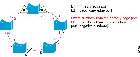
Note ![]() You would never enter an offset value of 1 because that is the offset number of the primary edge port itself.
You would never enter an offset value of 1 because that is the offset number of the primary edge port itself.
If you have configured a preempt delay time by entering the rep preempt delay seconds interface configuration command and a link failure and recovery occurs, VLAN load balancing begins after the configured preemption time period elapses without another link failure. The alternate port specified in the load-balancing configuration blocks the configured VLANs and unblocks all other segment ports. If the primary edge port cannot determine the alternate port for VLAN balancing, the default action is no preemption.
Each port in a segment has a unique port ID. The port ID format is similar to the one used by the spanning tree algorithm: a port number (unique on the bridge) associated to a MAC address (unique in the network). To determine the port ID of a port, enter the show interface interface-id rep detail privileged EXEC command.
Examples
This example shows how to configure REP VLAN load balancing on the Switch B primary edge port (Gigabit Ethernet port 0/1) and to configure Gigabit Ethernet port 0/2 of Switch A as the alternate port to block VLANs 1 to 100. The alternate port is identified by its port ID, shown in bold in the output of the show interface rep detail command for the Switch A port.
Switch A# show interface gigabitethernet0/2 rep detail
GigabitEthernet0/2 REP enabled
Segment-id: 2 (Segment)
PortID: 0080001647FB1780
Preferred flag: No
Operational Link Status: TWO_WAY
Current Key: 007F001647FB17800EEE
Port Role: Open
Blocked Vlan: <empty>
Admin-vlan: 1
Preempt Delay Timer: 35 sec
Load-balancing block port: none
Load-balancing block vlan: none
STCN Propagate to:
PDU/TLV statistics:
LSL PDU rx: 107122, tx: 192493
Switch B# config t
Switch (config)# interface gigabitethernet0/1
Switch (config-if)# rep block port id 0080001647FB1780 vlan 1-100
Switch (config-if)# exit
This example shows how to configure VLAN load balancing by using a neighbor offset number and how to verify the configuration by entering the show interfaces rep detail privileged EXEC command:
Switch# config t
Switch (config)# interface gigabitethernet0/2
Switch (config-if)# rep block port 6 vlan 1-110
Switch (config-if)# end
Switch# show interface gigabitethernet0/2 rep detail
GigabitEthernet0/2 REP enabled
Segment-id: 2 (Segment)
PortID: 0080001647FB1780
Preferred flag: No
Operational Link Status: TWO_WAY
Current Key: 007F001647FB178009C3
Port Role: Open
Blocked Vlan: <empty>
Admin-vlan: 3
Preempt Delay Timer: 35 sec
Load-balancing block port: 6
Load-balancing block vlan: 1-110
STCN Propagate to: none
LSL PDU rx: 1466780, tx: 3056637
HFL PDU rx: 2, tx: 0
BPA TLV rx: 1, tx: 2119695
BPA (STCN, LSL) TLV rx: 0, tx: 0
BPA (STCN, HFL) TLV rx: 0, tx: 0
EPA-ELECTION TLV rx: 757406, tx: 757400
EPA-COMMAND TLV rx: 1, tx: 1
EPA-INFO TLV rx: 178326, tx: 178323
Related Commands
rep lsl-age-timer
To configure the Link Status Layer (LSL) age timer for the time period that the Resilient Ethernet Protocol (REP) interface remains up without receiving a hello from the REP neighbor, use the rep lsl-age-timer command in interface configuration mode on a REP port. To return to the default time, use the no form of this command.
rep lsl-age timer value
no rep lsl-age timer
Syntax Description
value |
The age-out time in milliseconds. The range is from 920 to 10000 ms in 40-ms increments. The default is 5000 ms (5 seconds). |
Defaults
The REP link shuts down if it does not receive a hello message from a neighbor for 5000 ms.
Command Modes
Interface configuration
Command History
|
|
|
|---|---|
12.2(52)EY |
This command was introduced. |
Usage Guidelines
The LSL hello timer is set to the age-timer value divided by 3 so that there should be at least two LSL hellos sent during the LSL age timer period. If no hellos are received within that time, the REP link shuts down.
In Cisco IOS Release 12.2(52)SE, the LSL age-timer range changed from 3000 to 10000 ms in 500-ms increments to 120 to 10000 ms in 40-ms increments. If the REP neighbor device is not running Cisco IOS Release 12.2(52)SE or later, you must use the shorter time range because the device does not accept values out of the earlier range.
EtherChannel port channel interfaces do not support LSL age-timer values less than 1000 ms. If you try to configure a value less than 1000 ms on a port channel, you receive an error message and the command is rejected.
You can verify the configured ageout time by entering the show interfaces rep detail privileged EXEC command.
Examples
This example shows how to configure the REP LSL age timer on a REP link to 7000 ms:
Switch (config)# interface gigabitethernet0/2
Switch (config-if)# rep lsl-age-timer 7000
Switch (config-if)# exit
Related Commands
|
|
|
|---|---|
show interfaces rep [detail] |
Displays REP configuration and status for all interfaces or the specified interface, including the configured LSL age-out timer value. |
rep preempt delay
To configure a waiting period after a segment port failure and recovery before Resilient Ethernet Protocol (REP) VLAN load balancing is triggered, use the rep preempt delay command in interface configuration mode on the REP primary edge port. To remove the configured delay, use the no form of this command.
rep preempt delay seconds
no rep preempt delay
Syntax Description
seconds |
Sets the number of seconds to delay REP preemption. The range is 15 to 300. |
Defaults
No preemption delay is set. If you do not enter the rep preempt delay command, the default is manual preemption with no delay.
Command Modes
Interface configuration
Command History
|
|
|
|---|---|
12.2(52)EY |
This command was introduced. |
Usage Guidelines
You must enter this command on the REP primary edge port.
You must enter this command and configure a preempt time delay if you want VLAN load balancing to automatically trigger after a link failure and recovery.
If VLAN load balancing is configured, after a segment port failure and recovery, the REP primary edge port starts a delay timer before VLAN load balancing occurs. Note that the timer restarts after each link failure. When the timer expires, the REP primary edge alerts the alternate port to perform VLAN load balancing (configured by using the rep block port interface configuration command) and prepares the segment for the new topology. The configured VLAN list is blocked at the alternate port, and all other VLANs are blocked at the primary edge port.
You can verify the configuration by entering the show interfaces rep privileged EXEC command.
Examples
This example shows how to configure a REP preemption time delay of 100 seconds on the primary edge port:
Switch (config)# interface gigabitethernet0/1
Switch (config-if)# rep preempt delay 100
Switch (config-if)# exit
Related Commands
|
|
|
|---|---|
rep block port |
Configures VLAN load balancing. |
show interfaces rep |
Displays REP configuration and status for all interfaces or a specified interface. |
rep preempt segment
To manually start Resilient Ethernet Protocol (REP) VLAN load balancing on a segment, use the rep preempt segment command in privileged EXEC mode.
rep preempt segment segment_id
Syntax Description
segment-id |
ID of the REP segment. The range is from 1 to 1024. |
Defaults
Manual preemption is the default behavior.
Command Modes
Privileged EXEC
Command History
|
|
|
|---|---|
12.2(52)EY |
This command was introduced. |
Usage Guidelines
When you enter the rep preempt segment segment-id command, a confirmation message appears before the command is executed because preemption can cause network disruption.
Enter this command on the switch on the segment that has the primary edge port.
If you do not configure VLAN load balancing, entering this command results in the default behavior—the primary edge port blocks all VLANs.
You configure VLAN load balancing by entering the rep block port {id port-id | neighbor_offset | preferred} vlan {vlan-list | all} interface configuration command on the REP primary edge port before you manually start preemption.
There is not a no version of this command.
Examples
This example shows how to manually trigger REP preemption on segment 100 with the confirmation message:
Switch)# rep preempt segment 100
The command will cause a momentary traffic disruption.
Do you still want to continue? [confirm]
Related Commands
|
|
|
|---|---|
rep block port |
Configures VLAN load balancing. |
show interfaces rep [detail] |
Displays REP configuration and status for all interfaces or the specified interface. |
rep segment
To enable Resilient Ethernet Protocol (REP) on an interface and to assign a segment ID to it, use the rep segment command in interface configuration mode. To disable REP on the interface, use the no form of this command.
rep segment segment-id [edge [no-neighbor] [primary]] [preferred]
no rep segment
Syntax Description
Defaults
REP is disabled on the interface.
When REP is enabled on an interface, the default is for the port to be a regular segment port.
Command Modes
Interface configuration
Command History
|
|
|
|---|---|
12.2(52)EY |
This command was introduced. |
Usage Guidelines
REP ports must be Layer 2 trunk ports.
REP ports should not be configured as access ports.
You must configure two edge ports on each REP segment, a primary edge port and a port to act as a secondary edge port. If you configure two ports in a segment as the primary edge port, for example ports on different switches, the configuration is allowed, but the REP selects one of them to serve as the segment primary edge port.
•![]() REP ports follow these rules:
REP ports follow these rules:
–![]() There is no limit to the number of REP ports on a switch; however, only two ports on a switch can belong to the same REP segment.
There is no limit to the number of REP ports on a switch; however, only two ports on a switch can belong to the same REP segment.
–![]() If only one port on a switch is configured in a segment, the port should be an edge port.
If only one port on a switch is configured in a segment, the port should be an edge port.
–![]() If two ports on a switch belong to the same segment, they must be both edge ports, both regular segment ports, or one regular port and one edge no-neighbor port. An edge port and regular segment port on a switch cannot belong to the same segment.
If two ports on a switch belong to the same segment, they must be both edge ports, both regular segment ports, or one regular port and one edge no-neighbor port. An edge port and regular segment port on a switch cannot belong to the same segment.
–![]() If two ports on a switch belong to the same segment and one is configured as an edge port and one as a regular segment port (a misconfiguration), the edge port is treated as a regular segment port.
If two ports on a switch belong to the same segment and one is configured as an edge port and one as a regular segment port (a misconfiguration), the edge port is treated as a regular segment port.
If you configure two ports in a segment as the primary edge port, for example ports on different switches, the REP selects one of them to serve as the segment primary edge port. Enter the show rep topology privileged EXEC command on a port in the segment to verify which port is the segment primary edge port.
REP interfaces come up in a blocked state and remain in a blocked state until notified that it is safe to unblock. You need to be aware of this to avoid sudden connection losses.
You should configure REP only in networks with redundancy. Configuring REP in a network without redundancy causes loss of connectivity.
In networks where ports on a neighboring switch do not support REP, you can configure the non-REP facing ports as edge no-neighbor ports. These ports inherit all properties of edge ports and you can configure them as any other edge port, including to send STP or REP topology change notices to the aggregation switch. In this case, the STP topology change notice (TCN) that is sent is a multiple spanning-tree (MST) STP message.
You can verify the configuration by entering the show interfaces rep privileged EXEC command. To verify which port in the segment is the primary edge port, enter the show rep topology privileged EXEC command.
When the no-neighbor keyword is specified the segment edge is configured with no external REP neighbor. However if rep stcn stp command is enabled MST will be enabled on the port.
Examples
This example shows how to enable REP on a regular (nonedge) segment port:
Switch (config)# interface gigabitethernet0/1
Switch (config-if)# rep segment 100
This example shows how to enable REP on a port and to identify the port as the REP primary edge port:
Switch (config)# interface gigabitethernet0/2
Switch (config-if)# rep segment 100 edge primary
This example shows how to configure the same configuration when the interface has no external REP neighbor:
Switch# configure terminal
Switch (conf)# interface gigabitethernet0/1
Switch (conf-if)# rep segment 100 edge no-neighbor primary
This example shows how to enable REP on a port and to identify the port as the REP secondary edge port:
Switch (config)# interface gigabitethernet0/2
Switch (config-if)# rep segment 100 edge
Related Commands
rep stcn
To configure a port to send Resilient Ethernet Protocol (REP) segment topology change notifications (STCNs) to another interface, to other segments, or to Spanning Tree Protocol (STP) networks, use the rep stcn command in interface configuration mode on a REP edge port. To disable the sending of STCNs to the interface, segment, or STP network, use the no form of this command.
rep stcn {interface interface-id | segment id-list | stp}
no rep stcn {interface | segment | stp}
Syntax Description
Defaults
Transmission of STCNs to other interfaces, segments, or STP networks is disabled.
Command Modes
Interface configuration
Command History
|
|
|
|---|---|
12.2(52)EY |
This command was introduced. |
Usage Guidelines
Enter this command on a segment edge port.
You use this command to notify other portions of the Layer 2 network of topology changes that occur in the local REP segment. This removes obsolete entries in the Layer 2 forwarding table in other parts of the network, which allows faster network convergence.
You can verify the configuration by entering the show interfaces rep detail privileged EXEC command.
When you configure rep stcn stp the STCNs are sent to an stp network. However where no-neighbor keyword is specified MST will be enabled on the port.
Examples
This example shows how to configure the REP primary edge port to send STCNs to segments 25 to 50:
Switch (config)# interface gigabitethernet0/2
Switch (config-if)# rep stcn segment 25-50
Switch (config-if)# exit
Related Commands
|
|
|
|---|---|
show interfaces rep [detail] |
Displays REP configuration and status for all interfaces or the specified interface. |
reserved-only
To allocate only reserved addresses in the Dynamic Host Configuration Protocol (DHCP) address pool, use the reserved-only command in DHCP pool configuration mode. to return to the default, use the no form of the command.
reserved-only
no reserved-only
Syntax Description
This command has no arguments or keywords.
Defaults
The default is to not restrict pool addresses
Command Modes
Privileged EXEC
Command History
|
|
|
|---|---|
12.2(52)EY |
This command was introduced. |
Usage Guidelines
Entering the reserved-only command restricts assignments from the DHCP pool to preconfigured reservations. Unreserved addresses that are part of the network or on pool ranges are not offered to the client, and other clients are not served by the pool.
By entering this command, users can configure a group of switches with DHCP pools that share a common IP subnet and that ignore requests from clients of other switches.
To access DHCP pool configuration mode, enter the ip dhcp pool name global configuration command.
Examples
This example shows how to configure the DHCP pool to allocate only reserved addresses:
Switch# config t
Enter configuration commands, one per line. End with CNTL/Z.
Switch(config)# ip dhcp pool test1
Switch(dhcp-config)# reserved-only
You can verify your settings by entering the show ip dhcp pool privileged EXEC command.
Related Commands
|
|
|
|---|---|
show ip dhcp pool |
Displays the DHCP address pools. |
 Feedback