Cisco Business 110 Series Unmanaged Switches Mounting Guide
Installing the Switch
Before you install the switch, be sure to unpack and inspect the switch for damage or missing components. If anything is missing or damaged, contact your customer service representative immediately.
This section is specific to the CBS 110 switches. The switch can be installed on a rack, on a wall or on top of a desk or shelf with or without mounting screws.
Option 1
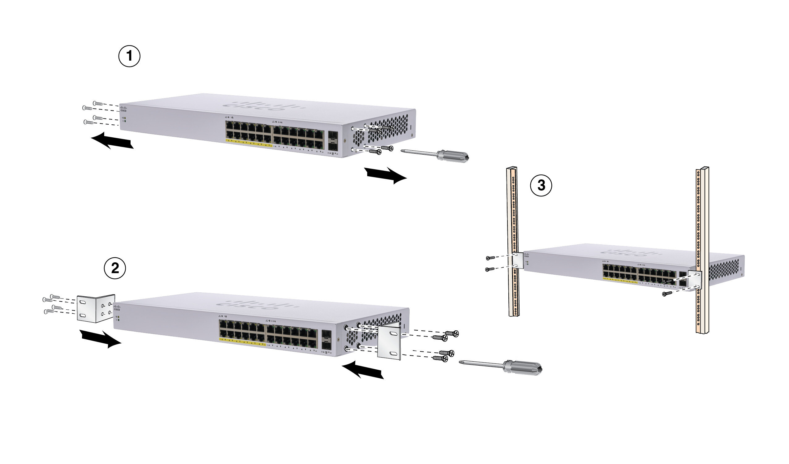
To use the rack-mount option, follow these steps:
Procedure
| Step 1 |
Remove the screws (when applicable) from the side panel on the switch. |
| Step 2 |
Align the screw holes in the brackets to the holes in the switch and attach the brackets with the screws. |
| Step 3 |
Align the brackets on the switch to the rack at the desired height and attach the switch to the brackets using the screws. |
Safety Instructions For Rack Mounting
|
Safety Instructions Rack Mount |
The following or similar rack-mount instructions are included with the installation instructions. |
|||
|
A) Elevated Operating Temperature- If installed in a closed or multi-rack assembly, the operating temperature of the rack environment may be greater than room temperature Therefore, consideration should be given to installing the equipment in an environment compatible with the maximum temperature (Tma) specified. |
||||
|
B) Reduced Air Flow - Installation of the equipment in the rack should be such that the amount of air flow required for safe operation of the equipment is not compromised. |
||||
|
C) Mechanical Loading - Mounting of the equipment in the rack should be such that a hazardous condition is not achieved due to uneven mechanical loading. |
||||
|
D) Circuit Overloading - Consideration should be given to the connection of the equipment to the supply circuit and the effect that overloading of the circuits might have on over current protection and supply wiring. Appropriate consideration of equipment nameplate ratings should be used when addressing these concerns. |
||||
|
E) Reliable Grounding - Reliable grounding of rack-mounted equipment should be maintained. Particular attention should be given to supply connections other than direct connections to the branch current (e.g. use of power strips).” |
||||
Wall-mount
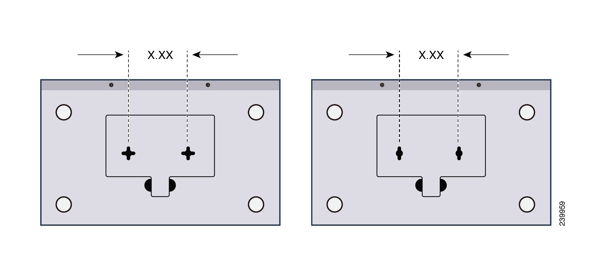
|
X.XX= Distance between mount holes |
|
|---|---|
|
CBS110-5T-D |
1.7 in/43 mm |
|
CBS110-8T-D, CBS110-8PP-D |
2.5 in/63 mm |
|
CBS110-16T, CBS110-16PP |
3.7 in/94 mm |
To use the wall mount option, follow these steps:
Procedure
| Step 1 |
Attach the two screws to the wall-mount slots of the switch lineup with the screws. |
||||||||||||||||||||||||
| Step 2 |
Maneuver the switch to insert the screws into the two wall-mount slots. Wall-mount if needed (continued) 
|
||||||||||||||||||||||||
Desk Placement
To install the switch, set it on its four rubber pads and place it on a flat surface.
Ambient Temperature Ratings
|
Condition |
Temperature |
|---|---|
|
Storage Temperature @ sea level |
-20° C to +70° C |
|
Operating Temperature @ sea level |
0° C to +50° C |
|
Storage Relative Humidity @ sea level |
5% to 90% (Humidity) |
|
Operating Relative Humidity @ sea level |
10 to 90% RH no-condensing |
Get Support
|
110 Series Unmanaged Switches |
|
|
Regulatory, Compliance, and Safety Information |
http://www.cisco.com/go/cbs110 Click on the Resources tab, and scroll down to Technical Documentation. |
|
End User License Agreement |
|
|
Warranty Information |
|
|
EU lot 26 related test result |
http://www.cisco.com/go/eu-lot26-results |
 Feedback