Configuring VLAN Mapping

About VLAN Mapping


Note

This feature is not supported on the C9500-12Q, C9500-16X, C9500-24Q, C9500-40X models of the Cisco Catalyst 9500 Series Switches.

In a typical deployment of VLAN mapping, you want the service provider to provide a transparent switching infrastructure that treats customers’ switches at the remote location as a part of the local site. This allows customers to use the same VLAN ID space and run Layer 2 control protocols seamlessly across the provider network. In such scenarios, we recommend that service providers do not impose their VLAN IDs on their customers.

One way to establish translated VLAN IDs (S-VLANs) is to map customer VLANs to service-provider VLANs (called VLAN ID translation) on trunk ports connected to a customer network. Packets entering the port are mapped to a service provider VLAN (S-VLAN) based on the port number and the packet’s original customer VLAN-ID (C-VLAN).

Service providers’s internal assignments might conflict with a customer’s VLAN. To isolate customer traffic, a service provider could decide to map a specific VLAN into another one while the traffic is in its cloud.

Deployment Example

In the below Figure, the service provider provides Layer 2 VPN service to two different customers, A and B. The service provider separates the data and control traffic between the two customers and from the providers’ own control traffic. The service provider network must also be transparent to the customer edge devices.

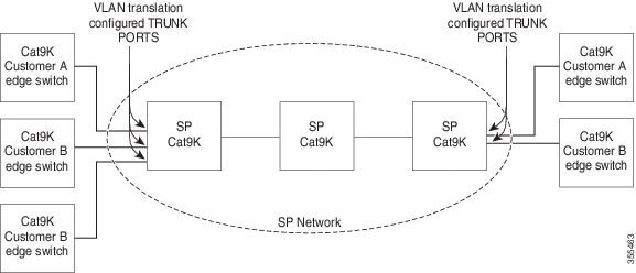
All forwarding operations on the Catalyst 9000 series switch are performed using S-VLAN and not C-VLAN information because the VLAN ID is mapped to the S-VLAN on ingress.


Note

When you configure features on a port configured for VLAN mapping, you always use the S-VLAN rather than the customer VLAN-ID (C-VLAN).

On an interface configured for VLAN mapping, the specified C-VLAN packets are mapped to the specified S-VLAN when they enter the port. Symmetrical mapping to the customer C-VLAN occurs when packets exit the port. The switch supports One-to-one VLAN mapping on trunk ports. One-to-one VLAN mapping occurs at the ingress and egress of the port and maps the customer C-VLAN ID in the 802.1Q tag to the service-provider S-VLAN ID. You can also specify that packets with all other Vlan Ids are forwarded.

Mapping Customer VLANs to Service-Provider VLANs

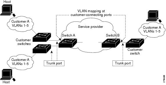
Figure shows a topology where a customer uses the same VLANs in multiple sites on different sides of a service-provider network. You map the customer VLAN IDs to service-provider VLAN IDs for packet travel across the service-provider backbone. The customer VLAN IDs are retrieved at the other side of the service-provider backbone for use in the other customer site. Configure the same set of VLAN mappings at a customer-connected port on each side of the service-provider network.

Configuration Guidelines for VLAN Mapping


Note

  • By default, no VLAN mapping is configured.

  • Maximum number of VLAN mapping configurations supported on Cisco Catalyst 9500 High Performance series switches is 1000 system wide.

  • Maximum number of VLAN mapping configurations supported on Cisco Catalyst 9500 series switches is 512 system wide.


Guidelines include the following:

  • If the VLAN mapping is enabled on an EtherChannel, the configuration does not apply to all member ports of the EtherChannel bundle and applies only to the EtherChannel interface.

  • To process control traffic consistently, either enable Layer 2 protocol tunneling (recommended), as follows:

    ! Device(config)# interface HundredGigE1/0/1 
    Device(config-if)# switchport mode trunk 
    Device(config-if)# switchport vlan mapping 20 300 
    Device(config-if)# l2protocol-tunnel stp 
    Device(config-if)# end 

    or insert a BPDU filter for spanning tree, as follows:

    Current configuration : 153 bytes
    !
    Device(config)# interface HundredGigE1/0/1
    Device(config-if)# switchport mode trunk
    Device(config-if)# switchport vlan mapping 10 20
    Device(config-if)# spanning-tree bpdufilter enable
    Device(config-if)# end 
  • To ensure consistent operation, do not use a native VLAN for translation.

  • C-VLAN and S-VLAN should be created and present in the allowed VLAN list of the trunk port where VLAN mapping is configured.

  • Default native VLANs, user-configured native VLANs, and reserved VLANs cannot be used for VLAN mapping.

  • Reserved VLANs between the range 1002-1005 are not allowed to be configured as S-VLANs.

  • One-to-One VLAN mapping can be configured only on trunk ports and not on dynamic trunk.

  • One-to-One VLAN mapping should be identical on both ports.

  • Merging of C-VLAN and S-VLAN spanning-tree topology is not supported in case of one-to-one vlan mapping.

  • Coexistence of QinQ S-VLAN as EVPN VNI or LISP VNI is not recommended.

One-to-one VLAN Mapping


Note

VLAN Mapping is supported only with the network-advantage license level.

To configure one-to-one VLAN mapping to map a customer VLAN ID to a service-provider VLAN ID, perform this task:

SUMMARY STEPS

  1. Switch# configure terminal
  2. Switch(config)# interface interface-id
  3. Switch(config-if)# switchport mode trunk
  4. Switch(config-if)# switchport vlan mapping vlan-id translated-id
  5. Switch(config)# spanning-tree bpdufilter enable
  6. Switch# end
  7. Switch# show vlan mapping
  8. Switch# copy running-config startup-config

DETAILED STEPS

  Command or Action Purpose
Step 1

Switch# configure terminal

Enters global configuration mode.

Step 2

Switch(config)# interface interface-id

Enters interface configuration mode for the interface connected to the service-provider network. You can enter a physical interface or an EtherChannel port channel.

Step 3

Switch(config-if)# switchport mode trunk

Configures the interface as a trunk port.

Step 4

Switch(config-if)# switchport vlan mapping vlan-id translated-id

Enters the VLAN IDs to be mapped:

  • vlan-id —the customer VLAN ID (C-VLAN) entering the switch from the customer network. The range is from 1 to 4094.

  • translated-id —the assigned service-provider VLAN ID (S-VLAN). The range is from 1 to 4094.

Step 5

Switch(config)# spanning-tree bpdufilter enable

To process control traffic consistently, either enable Layer 2 protocol tunneling (recommended) or insert a BPDU filter for spanning tree.
Step 6

Switch# end

Returns to privileged EXEC mode.

Step 7

Switch# show vlan mapping

Verifies the configuration.

Step 8

Switch# copy running-config startup-config

(Optional) Saves your entries in the configuration file.

Example

Use no switchport vlan mapping vlan-id translated-id command to remove the VLAN mapping information. Entering no switchport vlan mapping all command deletes all mapping configurations.

This example shows how to map VLAN IDs 2 to 6 in the customer network to VLANs 101 to 105 in the service-provider network (Figure 3-5). You configure the same VLAN mapping commands for a port in Switch A and Switch B; the traffic on all other VLAN IDs are forwarded as normal traffic.

Switch(config)# interface gigabiethernet0/1

Switch(config-if)# switchport vlan mapping 2 101

Switch(config-if)# switchport vlan mapping 3 102

Switch(config-if)# switchport vlan mapping 4 103

Switch(config-if)# switchport vlan mapping 5 104

Switch(config-if)# switchport vlan mapping 6 105

Switch(config-if)# exit

In the previous example, at the ingress of the service-provider network, VLAN IDs 2 to 6 in the customer network are mapped to VLANs 101 to 105, in the service provider network. At the egress of the service provider network, VLANs 101 to 105 in the service provider network are mapped to VLAN IDs 2 to 6, in the customer network.


Note

Packets with VLAN IDs other than the ones with configured VLAN Mapping are forwarded as normal traffic.

Use show vlan mapping command to view information about configured vlans.

show vlan mapping

Total no of vlan mappings configured: 1

Interface Po5:

VLANs on wire Translated VLAN Operation

------------------------------ --------------- --------------

20 30 1-to-1