Campus Fabric

Information about Campus Fabric

Campus Fabric, also refered to as Software Defined Access, provides the basic infrastructure for building virtual networks on policy-based segmentation constructs. It is based on the Locator ID Separator Protocol (LISP) overlay network built on top of an arbitrary underlay network.

Overlay networks can run across all the underlay network devices or a subnet of these devices. Multiple overlay networks can spread across the same underlay network to support multitenancy.

Cisco IOS XE Everest 16.6.1 supports Layer 2 and Layer 3 overlay networks.

Campus Fabric Overlay provisioning uses three components to enable flexible attachment of users and devices, and enhanced security through user-based and device-group based policies:

  • Control Plane

  • Data Plane

  • Policy Plane

The Campus Fabric feature is supported on the Enterprise Services and IP Base software images.

Benefits of Provisioning a Campus Fabric Network

  • A hybrid Layer 2 and Layer 3 overlay offers the best of both these services.

  • Provides end-to-end segmentation using LISP Virtualization technology wherein only the Fabric Edge and Border nodes have to be LISP aware. The rest of the components are just IP forwarders.

  • Eliminates Spanning Tree Protocol (STP), improves link utilization, and brings in faster convergence and equal cost multipath (ECMP) load balancing.

  • Fabric header supports Secure Group Tag (SGT) propagation, which helps in having a uniform policy model across the network. SGT-based policy constructs are subnet independent.

  • Provides host mobility for both wired and wireless clients.

  • Use of LISP helps decouple the host address and its location, simplifying the routing operations, and improving scalability and support.

Understanding Fabric Domain Elements

Figure displays the elements that make up the fabric domain.

Figure 1. Elements of a Fabric Domain


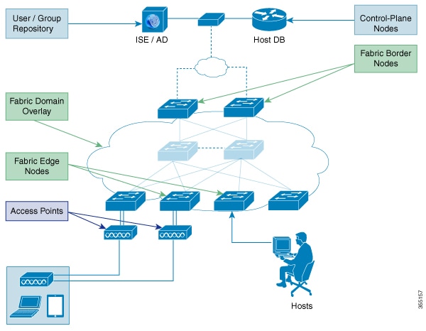
The following is a description of the fabric domain elements illustrated in the figure.

  • Fabric Edge Devices—Provide connectivity to users and devices that connect to the fabric domain. Fabric edge devices identify and authenticate end points, and register end-point ID information in the fabric host-tracking database. These devices encapsulate at ingress and decapsulate at egress, to forward traffic to and from the end points connected to the fabric domain.

  • Fabric Control-Plane Devices—Provide overlay reachability information and end points-to-routing locator mapping, in the host-tracking database. A control-plane device receives registrations from fabric edge devices having local end points, and resolves requests from edge devices to locate remote end points. You can configure up to three control-plane devices-internally (a fabric border device) and externally (a designated control-plane device, such as Cisco CSR1000v), to allow redundancy in your network.

  • Fabric Border Devices — Connect traditional Layer 3 networks or different fabric domains to the local domain, and translate reachability and policy information, such as virtual routing and forwarding (VRF) and SGT information, from one domain to another.

  • Virtual Contexts—Provide virtualization at the device level, using VRF to create multiple instances of Layer 3 routing tables. Contexts or VRFs provide segmentation across IP addresses, allowing for overlapped address space and traffic separation. You can configure up to 32 contexts in the fabric domain.

  • Host-Pools—Group end points that are present in the fabric domain into IP pools, and identify them with a VLAN ID and an IP subnet.

Campus Fabric Configuration Guidelines and Limitations

  • Configure no more than three control-plane devices in each fabric domain.

  • Configure no more than two border devices in each fabric domain..

  • Each fabric edge device supports up to 2000 end points.

  • Each control-plane device supports up to 5000 fabric edge device registrations.

  • Configure no more than 64 virtual contexts in each fabric domain.

  • Layer 2 (IPv4 host) and Layer 3 (IPv6 Host) LISP overlay functionality is supported on Cisco IOS XE Everest 16.6.1 and later releases.

  • On the edge device, Cisco TrustSec links are not supported on uplink interfaces connected to the underlay.

  • Layer 3 source group tags cannot be applied to uplink interfaces connected to the underlay.

  • Cisco IOS XE 16.6.1 does not support Dense Mode or Bidirectional Protocol Independent Multicast (PIM). Only PIM Sparse Mode (SM) and PIM Source Specific Multicast (SSM) modes are supported.

  • Multicast does not support group-to-rendezvous point (RP) mapping distribution mechanisms, Auto-RP, and Bootstrap Router (BSR). Only Static RP configuration is supported.

  • Multicast RP redundancy is not supported in the fabric domain.


Important

Virtual Extensible LAN (VXLAN) and LISP must be configured as part of campus fabric network. They are not supported as standalone features.


CLI Changes From Cisco IOS XE Everest 16.6.1

Starting Cisco IOS XE Everest 16.6.1, the CLI model for L2 LISP configuration is redesigned to better reflect the configuration flow and to configure LISP behavior that is specific to different functionalities such as support for Layer 2 MAC address as EID prefixes, and so on.

The following is a list of CLI changes:

  • The new CLI provides two levels of inheritance in two paths:

    • router lisp > service- called the global service or top service mode

    • router lisp > instance-id > service-called the instance-service mode

  • The end point identifier table,eid-table, is decoupled from the instance-id. You can now configure eid-table without specifying the instance-id. The hierarchy is router lisp > instance-id > service > eid-table.

  • You can have the common configuration under global service mode and instance ID-specific configuration under instance-service mode.

  • CLI that is configured at the global level of the hierarchy affects the operational state of all the instance services at lower levels of the hierarchy, unless explicitly overridden.

  • All the { ipv4 | ipv6} [proxy] {itr | etr} commands appear under their respective service mode without their address family prefix.

  • All the LISP show commands commence with the show lisp prefix.

  • A new command, locator default-set, which is configured at the global level marks one of the locater set as default.

  • service-ethernet is a new sub mode that enables Layer 2 MAC ID as EID space.


Note

After you enter the commands in the changed configuration style, the earlier CLIs are not supported. To switch to the earlier CLIs, reload the system.


How to Configure Campus Fabric

Configuring Campus Fabric involves the following stages:

  • Network Provisioning—Setting up the management plane and the underlay mechanism

  • Overlay Provisioning—Setting up the fabric overlay, which includes fabric edge and fabric border devices.

  • Policy Management—Setting up virtual contexts or VRFs, end point groups and policies.

Configure Fabric Edge Device

Follow these steps to configure fabric edge devices:

Before you begin

  • Configure a loopback0 IP address for each edge device to ensure that the device is reachable. Ensure that you run the ip lisp source-locator loopback0 command on the uplink interface.

  • Ensure that your underlay configuration is set up.

  • Configure control-plane devices and border devices in your fabric domain.

Procedure

  Command or Action Purpose
Step 1

configure terminal

Example:

Switch# configure terminal

Enters the global configuration mode.

Step 2

router lisp

Example:

Switch(config)# router lisp

Enters LISP configuration mode.

Step 3

locator-table name {default | vrf vrf-name}

Example:

Switch(config-router-lisp)# locator-table loc-table default

Associates a virtual routing and forwarding (VRF) table through which the router can reach the locator address space.

Step 4

locator-set name {ip-address {priority priority_value | weight weight} | auto-discover-rlocs

Example:

Switch(config-router-lisp-locator-table)# locator-set rloc1 1.1.1.1
priority 1 weight 1

Specifies a named locator set.

Step 5

IPv4-interface loopback Loopback-address { priority priority_value |weight weight}

Example:

Switch(config-router-lisp-locator-set)# IPv4-interface loopback0 priority 1 weight 1

Configure the loopback IP address to ensure that the device is reachable.

Step 6

exit-locator-set

Example:

Switch(config-router-lisp-locator-set)# exit-locator-set

Exits the locator-set configuration mode.

Step 7

instance-id instance

Example:

Switch(config-router-lisp)# instance-id 3

Creates a LISP EID instance to group multiple services. Configurations under this instance-id are applicable to all services underneath it.

Step 8

dynamic-eid dynamic-EID

Example:

Switch(config-router-lisp-instance)# dynamic-eid DEFAULT.EID.eng

Creates the dynamic-eid policy and enters the dynamic-eid configuration mode.

Step 9

database-mapping eid locator-set RLOC name

Example:

Switch(config-router-lisp-instance-dynamic-eid)# database-mapping 10.1.1.0/24 locator-set set1

Configures EID to RLOC mapping relationship.

Step 10

exit-dynamic-eid

Example:

Switch(config-router-lisp-instance-dynamic-eid)# exit-dynamic-eid

Exits dynamic-eid configuration mode

Step 11

service ipv4

Example:

Switch(config-router-lisp-instance)# service ipv4

Enables Layer 3 network services for the IPv4 address family and enters the service submode.

Step 12

eid-table vrf vrf-table

Example:

Switch(config-router-lisp-instance-service)# eid-table vrf vrf2

Associates the LISP instance ID configured earlier with a VRF table through which the end-point identifier address space is reachable.

Step 13

map-cache destination-eid map-request

Example:

Switch(config-router-lisp-instance-service)# map-cache 10.1.1.0/24 map-request

Generates a static map request for the destination EID.

Step 14

itr map-resolver map-resolver-address

Example:

Switch(config-router-lisp-instance-service)# itr map-resolver 2.1.1.6

Configures the map-resolver IP from where it needs to query the RLOC corresponding to destination EID IP.

Step 15

itr

Example:

Switch(config-router-lisp-instance-service)# itr

Specifies that this device acts as an Ingress Tunnel Router (ITR).

Step 16

etr map-server map-server-addr key {0 | 6} authentication key

Example:

Switch(config-router-lisp-instance-service)# etr map-server 2.1.1.6 key foo

Configures the locator address of the LISP map server to be used by the Egress Tunnel Router (ETR) when registering the IPv4 EIDs.

Step 17

etr

Example:

Switch(config-router-lisp-instance-service)# etr

Specifies that this device acts as an ETR.

Step 18

use-petr locator-address { priority priority_value | weight weight_value

Example:

Switch(config-router-lisp-instance-service)# use-petr 14.1.1.1

Configures the device to use Proxy Egress Tunnel Router (PETR).

Step 19

exit-service-ipv4

Example:

Switch(config-router-lisp-instance-service)# exit-service-ipv4

Exits service submode.

Step 20

exit-instance-id

Example:

Switch(config-router-lisp-instance)# exit-instance-id

Exits instance submode.

Configure a Fabric Edge Node as an Anycast Switch Virtual Interface (SVI)

Follow these steps to configure a fabric edge node as an anycast SVI:

Procedure

  Command or Action Purpose
Step 1

configure terminal

Example:

switch# configure terminal

Enters the global configuration mode.

Step 2

interface interface

Example:

switch(config)# interface vlan10

Enters SVI configuration mode.

Step 3

ip vrf forwarding vrf-name

Example:

Switch(config-if)# ip vrf forwarding EMP

Configures VRF on the interface.

Step 4

ip address ipv4-address

Example:

Switch(config-if)# ip address 192.168.10.1/24

Configures IP address on the interface.

Step 5

ip helper-address ipaddress

Example:

Switch(config-if)# ip helper-address 172.168.1.1

DHCP broadcasts will be forwarded as a unicast to this specific helper address rather than be dropped by the router

Step 6

lisp mobility

Example:

Swtich(config-if)# lisp mobility

Configures the interface to participate in LISP virtual machine mobility, which is dynamic EID roaming.

Configure a Fabric Edge Node as a DHCP Relay Agent

These steps describe how to configure fabric edge as a DHCP relay agent. For more information on configuring DHCP Client-Server in a Campus Fabric, see the Cisco IOS XE 16.6.1 Configure DHCP for Campus Fabric document.

Procedure

  Command or Action Purpose
Step 1

configure terminal

Example:

Switch# configure terminal

Enters the global configuration mode.

Step 2

ip dhcp snooping

Example:

Switch(config)# ip dhcp snooping 

Enables DHCP snooping globally.

Step 3

ip dhcp snooping vlan

Example:

Switch(config-if)# ip dhcp snooping vlan

Enables DHCP snooping on a specified VLAN.

Step 4

ip dhcp relay information option

Example:

Switch(config-if)# ip dhcp relay information option 

Enables the system to insert the DHCP relay agent information option (Option-82 field) in the messages forwarded to a DHCP server.

Configure a Fabric Border Device

Follow these steps to configure a fabric border device:

Procedure

  Command or Action Purpose
Step 1

configure terminal

Example:

Switch# configure terminal

Enters global configuration mode.

Step 2

router lisp

Example:

Switch(config)# router lisp

Enters LISP configuration mode.

Step 3

service ipv4

Example:

Switch(config-router-lisp)# service ipv4

Enables Layer 3 network services for the IPv4 address family and enters the service submode.

Step 4

map-cache destination-eid map-request

Example:

Switch(config-router-lisp-service)# map-cache 10.1.0.0/16 map-request

Specifies the destination EID to which map-requests are sent.

Step 5

encapsulation vxlan

Example:

Switch(config-router-lisp-service)# encapsulation vxlan

Specifies VXLAN-based encapsulation.

Step 6

itr map-resolver ip-address

Example:

Switch(config-router-lisp-service)# itr map-resolver 2.1.1.6

Configures the locator address of the LISP map resolver to which this device will send Map-Request messages for IPv4 EID-to-RLOC mapping resolutions.

Step 7

proxy-itr locator-address

Example:

Switch(config-router-lisp-service)# proxy-itr 7.7.7.7

Enables the LISP ITR functionality.

Step 8

proxy-etr

Example:

Switch(config-router-lisp-service)# proxy-etr 

Enables the PETR functionality on the device.

Step 9

exit-service-ipv4

Example:

Switch(config-router-lisp-service)# exit-service-ipv4

Exits service sub-mode.

Step 10

exit-router-lisp

Example:

Switch(config-router-lisp)# exit-router-lisp

Exits LISP configuration mode.

Configure Fabric Control Plane

Procedure

  Command or Action Purpose
Step 1

configure terminal

Example:

Switch# configure terminal

Enters global configuration mode.

Step 2

router lisp

Example:

Switch(config)# router lisp 

Enters LISP configuration mode.

Step 3

site site-name

Example:

Switch(config-router-lisp)# site fabric

Configures a LISP site on a control plane device and enters LISP site configuration mode.

Step 4

authentication-key key

Example:

Switch(config-router-lisp-site)# authentication-key lisp 

Configures the password used to create the Hashed Message Authentication Code (HMAC) Secure Hash Algorithm (SHA-1) hash for authenticating the map-register messages sent by edge devices when registering with the control-plane device.

Step 5

eid-record [instance-id instance-id ] record [route-tag tag] [accept-more-specifics ]

Example:

Switch(config-router-lisp-site)# eid-record instance-id 30 10.1.0.0/16

Configures a host pool or a list of endpoint identifier (EID) prefixes that are allowed in a map-register message sent by the edge device when registering with the control-plane device.

Step 6

exit-site

Example:

Switch(config-router-lisp-site)# exit-site

Exits LISP site configuration mode and returns to LISP configuration mode.

Step 7

exit-router-lisp

Example:

Switch(config-router-lisp)# exit-router-lisp 

Exits LISP configuration mode.

show Commands for Troubleshooting LISP Configuration

  • show lisp [router-lisp-id] {instance_id id | eid-table table} {ipv4 | ipv6 | ethernet} {database | map-cache | server [address-resolution]}

  • show lisp instance-id id ipv4 database

  • show lisp instance-id id ipv4 map-cache

  • show lisp service ipv4 summary

  • show lisp instance-id id { ipv4 | ipv6 | ethernet}

  • show lisp instance-id id dynamic-eid

Configuration Examples for LISP Configuration on Fabric Edge Node

Consider the following campus fabric topology:
Figure 2. Sample Campus Fabric topology

The following is the output of show running-configuration command on the fabric edge node in the Figure 1

interface Loopback0
ip address 2.1.1.1 255.255.255.255
!
interface Vlan10
mac-address ba25.cdf4.ad38
ip address 10.1.1.1 255.255.255.0
lisp mobility DEFAULT.EID.eng
end
!
interface Vlan11
mac-address ba25.cdf4.bd38
ip address 192.168.101.1 255.255.255.0
end
!
router lisp
locator-table default
locator-set set1
IPv4-interface Loopback0 priority 1 weight 1
exit-locator-set
!
locator default-set set1
service ipv4
proxy-itr 2.1.1.6
map-cache 0.0.0.0/0 map-request
itr map-resolver 2.1.1.6
etr map-server 2.1.1.6 key foo
etr map-server 2.1.1.6 proxy-reply
etr
use-petr 14.1.1.1
exit-service-ipv4
!
service ethernet
proxy-itr 2.1.1.6
map-cache 0.0.0.0/0 map-request
itr map-resolver 2.1.1.6
etr map-server 2.1.1.6 key foo
etr map-server 2.1.1.6 proxy-reply
etr
exit-service-ethernet
!
instance-id 30
dynamic-eid DEFAULT.EID.eng
database-mapping 10.1.1.0/24 locator-set set1
exit-dynamic-eid
!
service ipv4
eid-table default
exit-service-ipv4
!
exit-instance-id
!
instance-id 101
service ethernet
eid-table vlan 10
database-mapping mac locator-set set1
map-cache-limit 1000
database-mapping limit dynamic 2000
proxy-itr 2.1.1.6
map-cache 0.0.0.0/0 map-request
itr map-resolver 2.1.1.6
etr map-server 2.1.1.6 key foo
etr map-cache-ttl 10000
etr
exit-service-ethernet
!
exit-instance-id
!
instance-id 102
service ethernet
eid-table vlan 11
database-mapping mac locator-set set1
map-cache-limit 1000
database-mapping limit dynamic 2000

proxy-itr 2.1.1.6
map-cache 0.0.0.0/0 map-request
itr map-resolver 2.1.1.6
etr map-server 2.1.1.6 key foo
etr map-cache-ttl 10000
etr
exit-service-ethernet
!
exit-instance-id
exit-router-lisp
!

The following is the output of show running-configuration command on Control Plane in the Figure 1:

interface Loopback0
ip address 2.1.1.6 255.255.255.255
!
router lisp
locator-set WLC // enables wireless and access points to be registered.
3.3.3.20
exit-locator-set
!
service ipv4
map-server
map-resolver
exit-service-ipv4
!
service Ethernet // enables service ethernet on the map-server
map-server
map-resolver
exit-service-ethernet
!
map-server session passive-open WLC
site Shire
authentication-key cisco123
eid-record 10.1.1.0/24 accept-more-specifics
eid-record 20.1.1.0/24 accept-more-specifics
eid-record instance-id 1 any-mac
exit
!
exit-router-lisp

The following is the output of show running-configuration command on the fabric border node in the Figure 1

router lisp
locator-set default.RLOC
IPv4-Interface Loopback0 priority 10 weight 10
exit
!
service ipv4
sgt
itr map-resolver 2.1.1.6
proxy-etr
proxy-itr 2.1.1.4
exit-service-ipv4
!
instance-id 0
service ipv4
eid-table default
map-cache 10.1.1.0/24 map-request
map-cache 20.1.1.0/24 map-request
exit-service-ipv4
!
exit-instance-id
!
instance-id 100
service ipv4
eid-table vrf guest
map-cache 192.168.100.0/24 map-request
exit-service-ipv4
!
exit-instance-id
exit-router-lisp

Data Plane Security in Campus Fabric

Campus Fabric Data Plane Security ensures that only traffic from within a fabric domain can be decapsulated, by an edge device at the destination. Edge and border devices in the fabric domain validate that the source Routing Locator (RLOC), or the uplink interface address, carried by the data packet is a member of the fabric domain.

Data Plane Security ensures that the edge device source addresses in the encapsulated data packets cannot be spoofed. Packets from outside the fabric domain carry invalid source RLOCs that are blocked during decapsulation by edge and border devices.

Configure Data Plane Security on an Edge Device

Before you begin

  • Configure a loopback0 IP address for each edge device to ensure that the device is reachable. Ensure that you apply the ip lisp source-locator loopback0 command to the uplink interface.

  • Ensure that your underlay configuration is set up.

  • Ensure that you have configured edge, control plane, and border devices.

Procedure

  Command or Action Purpose
Step 1

router lisp

Example:

Switch(config)# router lisp

Enters LISP configuration mode.

Step 2

instance-id instance-id

Example:

Switch(config-router-lisp)# instance-id 3

Creates a LISP EID instance to group multiple services. Configuration under this instance ID applies to all the services underneath it.

Step 3

decapsulation filter rloc source member

Example:

Switch(config-router-lisp-instance)# decapsulation filter rloc source member 

Enables the validation of the source RLOC (uplink interface) addresses of encapsulated packets in the fabric domain.

Step 4

exit

Example:

Switch(config-router-lisp-instance)# exit

Exits LISP instance configuration mode and returns to LISP configuration mode.

Step 5

exit

Example:

Switch(config-router-lisp)# exit

Exits LISP configuration mode and returns to global configuration mode.

Configure Data Plane Security on a Control Plane Device

Before you begin

  • Configure a loopback0 IP address for each control plane device to ensure that the device is reachable. Ensure

    that you apply the ip lisp source-locator loopback0 command to the uplink interface.

  • Ensure that your underlay configuration is set up.

  • Ensure that you have configured edge, control-plane, and border devices.

Procedure

  Command or Action Purpose
Step 1

router lisp

Example:

Switch(config)# router lisp

Enters LISP configuration mode.

Step 2

map-server rloc members distribute

Example:

Switch(config-router-lisp)# map-server rloc members distribute

Enables the distribution of the list of EID prefixes, to the edge devices in the fabric domain.

Step 3

exit

Example:

Switch(config-router-lisp)# exit

Exits LISP configuration mode.

Step 4

show lisp [session [ established ] | vrf [ vrf-name [session [peer-address]]]]

Example:

Switch# show lisp session 
Displays reliable transport session information. If there is more than one transport session, the corresponding information is displayed.
Step 5

show lisp decapsulation filter [ IPv4-rloc-address | IPv6-rloc-address] [ eid-table eid-table-vrf | instance-id iid]

Example:

show lisp decapsulation filter
Displays the uplink interface address configuration details that are manually configured or discovered.

Configure a Fabric Border Device

Follow these steps to configure a fabric border device:

Procedure

  Command or Action Purpose
Step 1

configure terminal

Example:

Switch# configure terminal

Enters global configuration mode.

Step 2

router lisp

Example:

Switch(config)# router lisp

Enters LISP configuration mode.

Step 3

service ipv4

Example:

Switch(config-router-lisp)# service ipv4

Enables Layer 3 network services for the IPv4 address family and enters the service submode.

Step 4

map-cache destination-eid map-request

Example:

Switch(config-router-lisp-service)# map-cache 10.1.0.0/16 map-request

Specifies the destination EID to which map-requests are sent.

Step 5

encapsulation vxlan

Example:

Switch(config-router-lisp-service)# encapsulation vxlan

Specifies VXLAN-based encapsulation.

Step 6

itr map-resolver ip-address

Example:

Switch(config-router-lisp-service)# itr map-resolver 2.1.1.6

Configures the locator address of the LISP map resolver to which this device will send Map-Request messages for IPv4 EID-to-RLOC mapping resolutions.

Step 7

proxy-itr locator-address

Example:

Switch(config-router-lisp-service)# proxy-itr 7.7.7.7

Enables the LISP ITR functionality.

Step 8

proxy-etr

Example:

Switch(config-router-lisp-service)# proxy-etr 

Enables the PETR functionality on the device.

Step 9

exit-service-ipv4

Example:

Switch(config-router-lisp-service)# exit-service-ipv4

Exits service sub-mode.

Step 10

exit-router-lisp

Example:

Switch(config-router-lisp)# exit-router-lisp

Exits LISP configuration mode.

Security Group Tags and Policy Enforcement in Campus Fabric

Campus Fabric overlay propagates source group tags (SGTs) across devices in the fabric domain. Packets are encapsulated using virtual extensible LAN (VXLAN) and carry the SGT information in the header. The SGT mapped to the IP address of the edge device is carried within the encapsulated packet and propagated to the destination device, where the packet is decapsulated and the Source Group Access Control List (SGACL) policy is enforced.

For more information on Cisco TrustSec and Source Group Tags, see the Cisco TrustSec Switch Configuration Guide

Multicast Using Campus Fabric Overlay

You can use Campus Fabric overlay to carry multicast traffic over core networks that do not have native multicast capabilities. Campus Fabric overlay allows unicast transport of multicast traffic with head-end replication in the edge device.

Note

Only Protocol Independent Multicast (PIM) Sparse Mode and PIM Source Specific Multicast (SSM) are supported in Campus Fabric; dense mode is not supported.


Information about LISP Multicast

LISP multicast includes the following features:

  • Mapping of multicast source addresses as LISP EIDs. (Destination group addresses are not topology dependent.)

  • Building the multicast distribution tree across LISP overlays.

  • Unicast head-end replication of multicast data packets from sources within a root ingress tunnel router site to receiver egress tunnel route.

  • Support for Any Source Multicast (ASM) and Source Specific Multicast (SSM) service models for unicast replication. Support for only SSM in core tree for multicast replication.

  • Support for various combinations of LISP and non-LISP capable source and receiver sites.

  • Support for IPv6 EIDs with head-end replication multicast mode.

  • IPv6 multicast routing is supported only in default VRF.

  • By default, IPv6 multicast is enabled on IPv6 interfaces. Hence, EID-facing interface does not require explicit IPv6 multicast configuration.


Note

If a LISP xTR is also a PIM First Hop Router (FH) or a Rendezvous Point (RP), and the device is only receiving traffic, ensure that at least one interface on the device is covered by local LISP database mapping. No additional configuration is required to ensure that the proper address is selected.


Configure IPv4 Layer 3 LISP Multicast

Procedure

  Command or Action Purpose
Step 1

configure terminal

Example:

Switch# configure terminal

Enters global configuration mode.

Step 2

ip multicast-routing

Example:

Switch(config)# ip multicast-routing

Enables IP multicast routing.

Step 3

Enter one of the following:

  • ip pim rp-address rp-address
  • ip pim ssm {default | range {access-list-name | access-list-number}

Example:

Switch(config-if)# ip pim rp-address 66.66.66.66

Statically configures the address of a PIM RP for multicast groups.

Defines the Source Specific Multicast (SSM) range of IP multicast addresses.

Step 4

interface LISP-interface number

Example:

Switch(config-if)# interface lisp0

Specifies the LISP interface and the subinterface on which to enable PIM sparse mode.

Step 5

Enter one of the following:

  • ip pim sparse-mode
  • ip pim transport multicast

Example:

Switch(config-if)# ip pim sparse-mode 

Enables PIM on the interface for the sparse-mode operation.

Enables PIM on the interface for the sparse-mode operation. Use the ip pim transport multicast command when the core network has native multicast capabilities.

Step 6

exit

Example:

Swtich(config-if)# exit

Exits the interface configuration mode and enters global configuration mode.

Step 7

interface interface-type interface-number

Example:

Switch(config)# interface GigabitEthernet0/1

Configures the interface facing the end point, and enters interface configuration mode.

Step 8

ip pim sparse-mode

Example:

Switch(config-if)# ip pim sparse-mode

Enables PIM on the interface for sparse-mode operation.

Step 9

end

Example:

Swtich(config-if)# end

Ends the current configuration session and returns to privileged EXEC mode.

Configure Layer 2 Overlay Broadcast

Procedure

  Command or Action Purpose
Step 1

configure terminal

Example:

Switch# configure terminal

Enters global configuration mode.

Step 2

router lisp

Example:

Switch(config)# router lisp

Enters LISP configuration mode.

Step 3

instance-id instance

Example:

Switch(config-router-lisp)# instance-id 0

Creates a LISP EID instance to group multiple services. Configurations under this instance-id applies to all services underneath it.

Step 4

service ethernet

Example:

Switch(config-router-lisp-instance)# service ethernet

Enables Layer 2 network services and enters service submode.

Step 5

eid-table vlan vlan-number

Example:

Switch(config-router-lisp-instance-service)# eid-table vlan 3

Associates the LISP instance-id configured earlier with a VLAN through which the endpoint identifier address space is reachable.

Step 6

broadcast-underlay multicast-group

Example:

Switch(config-router-lisp-instance-service)# broadcast-underlay 225.1.1.1

Specifies the multicast group used by the underlay to carry the overlay Layer 2 broadcast traffic.

Step 7

exit-service-ethernet

Example:

Switch(config-router-lisp-instance-service)# exit-service-ethernet 

Exits service sub mode.

Step 8

exit-instance-id

Example:

Switch(config-router-lisp-instance)# exit-instance-id

Exits instance mode..

show Commands for Troubleshooting LISP Multicast Configuration

  • show ip pim vrf vrf_name rp mapping

  • show ip pim vrf vrf_name neighbor

  • show ip pim vrf vrf_name tunnel

  • show ip mroute vrf vrf_name

  • show ip mfib vrf vrf_name

  • show ip mfib vrf vrf_name count

  • show ip multicast interface

Configuration Examples for LISP Multicast

Consider the following topology in campus fabric:
Figure 3. Campus Fabric Topology to Configure Multicast

The following is a sample configuration of LISP multicast on fabric edge node FE1 in the figure Figure 1

ip multicast-routing
ip pim ssm default
!
interface Loopback0
ip address 11.1.1.1 255.0.0.0
!
interface Loopback100
ip address 66.66.66.66 255.255.255.255
ip pim sparse-mode
!
interface GigabitEthernet0/1
ip address 90.0.0.1 255.255.255.0
ip pim sparse-mode
!
Interface Vlan100
ip address 100.0.0.1 255.255.0.0
no ip redirects
ip local-proxy-arp
ip pim sparse-mode
ip route-cache same-interface
no lisp mobility liveness test
lisp mobility vl_100
ip pim sparse-mode
!
interface GigabitEthernet1/0/1
switchport access vlan 100
switchport mode access
!
!
interface LISP0
ip pim sparse-mode
ip pim lisp transport multicast

!
router lisp
locator-table default
locator-set rloc_1
  IPv4-interface Loopback0 priority 1 weight 1
  exit-locator-set
!
instance-id 0
  dynamic-eid vl_100
   database-mapping 100.0.0.0/16 locator-set rloc_1
   exit-dynamic-eid
  !
  service ipv4
   eid-table default
   database-mapping 66.66.66.66/32 locator-set rloc_1
   itr map-resolver 30.3.1.1
   itr
   etr map-server 30.3.1.1 key lisp
   etr
   use-petr 14.1.1.1
   exit-service-ipv4
  !
  exit-instance-id
!
encapsulation vxlan
exit-router-lisp
!
ip pim rp-address 66.66.66.66

The following is a sample configuration of control plane (MS/MR) in Figure 1

interface Loopback0
ip address 30.3.1.1 255.255.255.255
!
interface GigabitEthernet0/1
ip address 90.0.0.2 255.255.255.0
Ip pim sparse-mode
!
interface GigabitEthernet0/2
ip address 90.1.0.2 255.255.255.0
Ip pim sparse-mode
!
router lisp
site Fabric
authentication-key lisp
eid-record 100.0.0.0/16 accept-more-specifics
eid-record 66.66.66.66/32 accept-more-specifics
eid-record 77.77.77.77/32 accept-more-specifics
eid-record 88.88.88.88/32 accept-more-specifics
exit
!
ipv4 map-server
ipv4 map-resolver
exit

Feature History for Campus Fabric

Release

Modification

Cisco IOS XE Everest 16.6.1

Support for auto commands removed. New mode of CLI introduced.