The documentation set for this product strives to use bias-free language. For the purposes of this documentation set, bias-free is defined as language that does not imply discrimination based on age, disability, gender, racial identity, ethnic identity, sexual orientation, socioeconomic status, and intersectionality. Exceptions may be present in the documentation due to language that is hardcoded in the user interfaces of the product software, language used based on RFP documentation, or language that is used by a referenced third-party product. Learn more about how Cisco is using Inclusive Language.
Restrictions for DHCP Relay in BGP EVPN VXLAN Fabric
Interworking of BGP EVPN VXLAN with DHCP relay is supported in the following scenarios only when VRF-Lite is configured on
the border VTEP, and the border VTEP is connected to the DHCP server through an external router.
DHCP client in the tenant VRF and DHCP server in the Layer 3 default VRF.
DHCP client in the tenant VRF and DHCP server in a different tenant VRF.
DHCP client in the tenant VRF and DHCP server in a non-default non-VXLAN VRF.
DHCPv6 relay is not supported.
Information About DHCP Relay in BGP EVPN VXLAN Fabric
DHCP relay is used to forward DHCP packets between host devices and a DHCP server. In a BGP EVPN VXLAN fabric, the VTEP can
be configured as a relay agent to provide DCHP relay services in a multi-tenant VXLAN environment.
With DHCP Relay, DHCP messages need to be sent through the same switch in both directions. The gateway IP address (GiAddr)
for DHCP Relay is commonly used for scope selection and DHCP response messages. In a BGP EVPN VXLAN fabric that has distributed
IP anycast gateway enabled, the DHCP messages can be returned to any switch that hosts the respective GiAddr.
Using DHCP relay in a BGP EVPN VXLAN fabric requires a different way of scope selection and a unique IP address for each switch
in the network. The unique Loopback interface for a switch becomes the GiAddr that is used to respond to the correct switch.
DHCP option 82, also referred to as DHCP option VPN, is used for scope selection, based on the Layer 2 VNI.
In a multi-tenant EVPN environment, DHCP relay uses the following sub-options of option 82:
Sub-Option 151(0x97)—Virtual Subnet Selection:
The virtual subnet selection sub-option is used to convey VRF-related information to the DHCP server in an MPLS VPN and a
VXLAN EVPN multi-tenant environment.
The server identifier, or server ID, override sub-option allows the DHCP relay agent to specify a new value for the server
ID option, which is inserted by the DHCP server in the reply packet. This sub-option allows the DHCP relay agent to act as
the actual DHCP server and all the renew requests are sent to the relay agent instead of being sent directly to the DHCP server.
The server ID override sub-option contains the incoming interface IP address, which is the IP address on the relay agent that
is accessible from the client. The DHCP client uses this information to send all the renew and release request packets to
the relay agent. The relay agent adds all the appropriate sub-options and then forwards the renew and release request packets
to the original DHCP server.
For this function, Cisco’s proprietary implementation is sub-option 152(0x98). Run the ip dhcp relay sub-option type cisco command in global configuration mode on the VTEP acting as the DHCP relay agent to implement the suboption and manage the
function.
The link selection sub-option provides a mechanism to separate the subnet or link, on which the DHCP client resides, from
the GiAddr. The DHCP server can use this to communicate with the relay agent. The relay agent sets the sub-option to the correct
subscriber subnet and the DHCP server uses this value to assign an IP address that is different from the GiAddr. The relay
agent sets the GiAddr to its own IP address to ensure that the DHCP messages can be forwarded over the network.
For this function, Cisco’s proprietary implementation is sub-option 150(0x96). Run the ip dhcp relay sub-option type cisco command in global configuration mode on the VTEP acting as the DHCP relay agent to manage the function.
DHCP relay is usually configured on the default gateway that faces the DHCP client. To automate IP addressing, a VTEP can
be configured as a DHCP relay agent in different ways, depending on whether the DHCP server is present in the same network,
the same VRF, or a different VRF compared to the DHCP client. When the DHCP server and DHCP client are in different VRFs,
traffic is forwarded across the tenant or VRF boundaries.
The following are the common DHCP relay deployment scenarios for a BGP EVPN VXLAN fabric:
DHCP client in the tenant VRF and DHCP server in the Layer 3 default VRF.
DHCP client in the tenant VRF and DHCP server in the same tenant VRF.
DHCP client in the tenant VRF and DHCP server in a different tenant VRF.
DHCP client in the tenant VRF and DHCP server in a non-default non-VXLAN VRF.
Note
The deployment scenarios 1, 3, and 4 are supported only when VRF-Lite is configured on the border VTEP, and the border VTEP
is connected to the DHCP server through an external router.
How to Configure DHCP Relay in BGP EVPN VXLAN Fabric
Perform the following set of procedures to configure BGP EVPN VLAN interworking with DHCP relay.
Configuring DHCP Relay on a VTEP
To configure DHCP relay on a VTEP, perform the following steps:
Procedure
Command or Action
Purpose
Step 1
enable
Example:
Device> enable
Enables privileged EXEC mode.
Enter your password, if prompted.
Step 2
configure terminal
Example:
Device# configure terminal
Enters global configuration mode.
Step 3
ip dhcp relay information option vpn
Example:
Device(config)# ip dhcp relay information option vpn
Enables the device to insert VPN suboptions into the DHCP relay agent information option in the messages forwarded to the
DHCP server and sets the GiAddr on the outgoing interface towards the DHCP server.
Step 4
ip dhcp relay information option
Example:
Device(config)# ip dhcp relay information option
Enables the system to insert a DHCP relay agent information option in the messages forwarded to the DHCP server.
Step 5
ip dhcp relay override gateway-ip-address link-selection
Example:
Device(config)# ip dhcp relay override giaddr link-selection
Sets the gateway IP address as the IP address of the DHCP relay agent and configures the server to assign an IP address that
is different from the GiAddr to the DHCP clients.
Step 6
ip dhcp compatibility suboption server-override standard
Example:
Device(config)# ip dhcp compatibility suboption server-override standard
Configures the DHCP client to use the Internet Assigned Numbers Authority (IANA) standard relay agent server ID override suboption.
Step 7
ip dhcp snooping vlan vlan-id-list
Example:
Device(config)# ip dhcp snooping vlan 201-202
Enables DHCP snooping on the specified list of VLANs.
Step 8
ip dhcp snooping
Example:
Device(config)# ip dhcp snooping
Enables DHCP snooping on the VTEP.
Step 9
end
Example:
Device(config)# end
Returns to privileged EXEC mode.
Configuring DHCP Relay on the Access SVI of a VTEP
Perform this procedure on all the VTEPs for each VLAN that is associated with the Layer 2 VNI configured in the EVPN VXLAN
network.
To configure DHCP relay on the access SVI of a VTEP, perform the following steps:
Procedure
Command or Action
Purpose
Step 1
enable
Example:
Device> enable
Enables privileged EXEC mode.
Enter your password, if prompted.
Step 2
configure terminal
Example:
Device# configure terminal
Enters global configuration mode.
Step 3
interface vlan vlan-id
Example:
Device(config)# interface Vlan 201
Enters interface configuration mode for the specified VLAN interface.
This VLAN interface acts as the GiAddr.
Step 4
vrf forwarding vrf-name
Example:
Device(config-if)# vrf forwarding green
Associates the VRF with the interface.
The interface must be associated with the same VRF for which the Layer 3 VNI has been configured for the EVPN VXLAN network.
Step 5
ip dhcp relay information option vpn-id
Example:
Device(config-if)# ip dhcp relay information option vpn-id
Enables the device to insert VPN suboptions into the DHCP relay agent information option in the messages forwarded to the
DHCP server and sets the GiAddr on the outgoing interface towards the DHCP server.
Step 6
ip dhcp relay source-interface Loopback loopback-interface-id
Example:
Device(config-if)# ip dhcp relay source-interface Loopback13
Configures the specified Loopback interface as the source interface for DHCP relay messages. The DHCP relay agent uses the
IP address of the source interface as the source IP address to relay messages.
Note
The IP address configured on the Loopback interface must be unique per VTEP per VRF.
Step 7
ip address ip-address
Example:
Device(config-if)# ip address 192.168.1.201 255.255.255.0
Sets the IP address for the VLAN interface.
Step 8
ip helper-address ip-address
Example:
Device(config-if)# ip helper-address 192.168.3.100
Sets the DHCP IP helper address for the VLAN interface.
Step 9
exit
Example:
Device(config-if)# exit
Exits interface configuration mode and returns to global configuration mode.
Step 10
end
Example:
Device(config)# end
Returns to privileged EXEC mode.
Configuring the Router Interface on the Border VTEP for DHCP Server Reachability
DHCP server reachability can be achieved through a physical Layer 3 interface or subinterface, or a Layer3 Portchannel interface.
To configure the router interface on the border VTEP for DHCP server rechability, perform the following steps:
Procedure
Command or Action
Purpose
Step 1
enable
Example:
Device> enable
Enables privileged EXEC mode.
Enter your password, if prompted.
Step 2
configure terminal
Example:
Device# configure terminal
Enters global configuration mode.
Step 3
interface vlanvlan-id
Example:
Device(config)# interface vlan 203
Enters interface configuration mode for the specified VLAN interface.
Step 4
vrf forwarding vrf-name
Example:
Device(config-if)# vrf forwarding green
Configures the SVI for the VLAN and associates the specified VRF with the interface.
Step 5
ip address ip-address
Example:
Device(config-if)# ip address 192.168.3.203 255.255.255.0
Configures the IP address for the VLAN.
Step 6
ipv6 address ipv6-address
Example:
Device(config-if)# ipv6 address 2001:203::203/64
Configures the IPv6 address for the VLAN.
Step 7
ipv6 enable
Example:
Device(config-if)# ipv6 enable
Enables IPv6 processing on the VLAN interface.
Step 8
exit
Example:
Device(config-if)# exit
Exits interface configuration mode and returns to global configuration mode.
Step 9
interface interface-id
Example:
Device(config)# interface GigabitEthernet1/0/30
Enters interface configuration mode for the specified interface.
Step 10
switchport access vlan vlan-id
Example:
Device(config-if)# switchport access vlan 203
Specifies the VLAN to be used as access VLAN when the interface is in access mode.
Step 11
switchport mode access
Example:
Device(config-if)# switchport mode access
Configures the interface as an access interface.
Step 12
exit
Example:
Device(config-if)# exit
Exits interface configuration mode and returns to global configuration mode.
Step 13
end
Example:
Device(config)# end
Returns to privileged EXEC mode.
Configuration Examples for DHCP Relay in BGP EVPN VXLAN Fabric
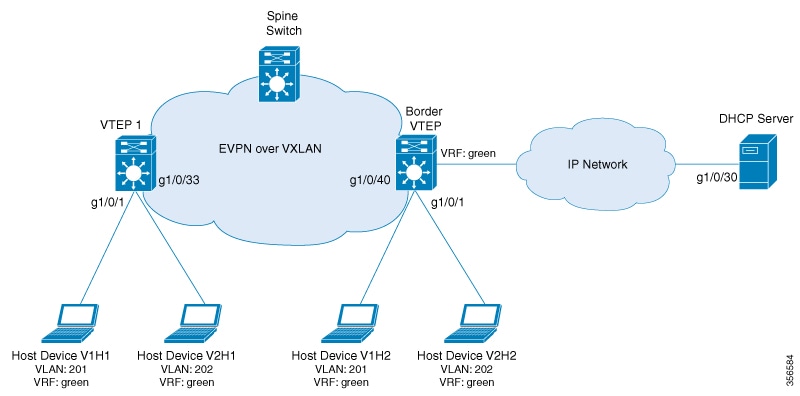
This section provides an example to show how DHCP relay is deployed in an EVPN VXLAN network when the DHCP client is in the
tenant VRF and the DHCP server is in the same tenant VRF. The example shows how to configure and verify DHCP relay for the
topology shown below:
The illustration shows an EVPN VXLAN network with two VTEPs, VTEP 1 and Border VTEP. Border VTEP and is connected to the DHCP
server.
DHCP server reachability can be achieved through a physical Layer 3 interface or subinterface, or a Layer3 Portchannel interface.
The example shown here deploys DHCP relay using an SVI interface and a switchport.
Table 1. Configuration Example for Deploying DHCP Relay in a BGP EVPN VXLAN Fabric when the DHCP Client and the DHCP Server are in
the Same Tenant VRF
VTEP 1
Border VTEP
VTEP 1# show running-config

<snip: only dhcp relevant config is shown>
ip dhcp relay information option vpn
ip dhcp relay information option
ip dhcp compatibility suboption link-selection standard
ip dhcp compatibility suboption server-override standard
ip dhcp snooping vlan 201-202
ip dhcp snooping
!
vlan configuration 200
 member vni 5000
vlan configuration 201
 member evpn-instance 1 vni 6000
vlan configuration 202
 member evpn-instance 2 vni 7000
!
interface Loopback13
 vrf forwarding green
 ip address 10.1.13.13 255.255.255.0

interface Vlan200
 description core svi for l3vni
 vrf forwarding green
 ip unnumbered Loopback0
 ip pim sparse-mode
 ipv6 enable
 no autostate

interface Vlan201
 vrf forwarding green
 ip dhcp relay information option vpn-id
 ip dhcp relay source-interface Loopback13
 ip address 192.168.1.201 255.255.255.0
 ip helper-address 192.168.3.100

interface Vlan202
 vrf forwarding green
 ip dhcp relay information option vpn-id
 ip dhcp relay source-interface Loopback13
 ip address 192.168.2.201 255.255.255.0
 ip helper-address 192.168.3.100

interface nve10
 no ip address
 source-interface Loopback0
 host-reachability protocol bgp
 member vni 7000 mcast-group 231.1.1.1
 member vni 6000 mcast-group 231.1.1.1
 member vni 5000 vrf green
Border VTEP# show running-config

<snip: only dhcp relevant config is shown>
ip dhcp relay information option vpn
ip dhcp relay information option
ip dhcp relay override giaddr link-selection
ip dhcp compatibility suboption server-override standard
ip dhcp snooping vlan 201-202
ip dhcp snooping
!
vlan configuration 200
 member vni 5000
vlan configuration 201
 member evpn-instance 1 vni 6000
vlan configuration 202
 member evpn-instance 2 vni 7000
!
interface Loopback14
 vrf forwarding green
 ip address 10.1.14.14 255.255.255.0

interface Vlan200
 description core svi for l3vni
 vrf forwarding green
 ip unnumbered Loopback0
 ip pim sparse-mode
 ipv6 enable
 no autostate

interface Vlan201
 vrf forwarding green
 ip dhcp relay information option vpn-id
 ip dhcp relay source-interface Loopback14
 ip address 192.168.1.201 255.255.255.0
 ip helper-address 192.168.3.100

interface Vlan202
 vrf forwarding green
 ip dhcp relay information option vpn-id
 ip dhcp relay source-interface Loopback14
 ip address 192.168.2.201 255.255.255.0
 ip helper-address 192.168.3.100


interface nve10
 no ip address
 source-interface Loopback0
 host-reachability protocol bgp
 member vni 7000 mcast-group 231.1.1.1
 member vni 6000 mcast-group 231.1.1.1
 member vni 5000 vrf green
DHCP server reachability is not configured on VTEP 1 as it is not a border VTEP.
interface Vlan203
 vrf forwarding green
 ip address 192.168.3.203 255.255.255.0
 ipv6 address 2001:203::203/64
 ipv6 enable
end

interface GigabitEthernet1/0/30
 description connected to DHCP server
 switchport access vlan 203
 switchport mode access
The following examples provide sample outputs for the show ip route vrf command on VTEP 1 and VTEP 2 to verify the reachability of the DHCP server from both VTEPs:
VTEP 1
The following example shows the output for the show ip route vrf command on VTEP 1:
VTEP 1# show ip route vrf green 192.168.3.100

Routing Table: green
Routing entry for 192.168.3.0/24
  Known via "bgp 10", distance 200, metric 0, type internal
  Last update from 10.2.2.20 on Vlan200, 18:28:43 ago
  Routing Descriptor Blocks:
  * 10.2.2.20 (default), from 10.5.5.50, 18:28:43 ago, via Vlan200
      opaque_ptr 0x7FEEA41D09C8
      Route metric is 0, traffic share count is 1
      AS Hops 0
      MPLS label: none
      MPLS Flags: NSF
Border VTEP
The following example shows the output for the show ip route vrf command on VTEP 2:
Border VTEP# show ip route vrf green 192.168.3.100

Routing Table: green
Routing entry for 192.168.3.0/24
  Known via "connected", distance 0, metric 0 (connected, via interface)
  Redistributing via bgp 10
  Advertised by bgp 10
  Routing Descriptor Blocks:
  * directly connected, via Vlan203
      Route metric is 0, traffic share count is 1
Packet Capture for Spine Switch
The following example shows the packet capture details for the spine switch from the topology configured above:
    6  12.749326   10.1.13.13 b^F^R 192.168.3.100 DHCP 449 DHCP Discover - Transaction ID 0x228f
    7  12.750463 192.168.3.100 b^F^R 10.1.13.13   DHCP 447 DHCP Offer    - Transaction ID 0x228f
    8  12.755776   10.1.13.13 b^F^R 192.168.3.100 DHCP 467 DHCP Request  - Transaction ID 0x228f
    9  12.756701 192.168.3.100 b^F^R 10.1.13.13   DHCP 447 DHCP ACK      - Transaction ID 0x228f
   11  12.803031 00:59:dc:50:ae:42 b^F^R ff:ff:ff:ff:ff:ff ARP 110 Gratuitous ARP for 192.168.2.3 (Reply)
   14  15.760480 00:59:dc:50:ae:42 b^F^R ff:ff:ff:ff:ff:ff ARP 110 Who has 192.168.2.201? Tell 192.168.2.3
   15  15.761058 38:0e:4d:9b:6a:42 b^F^R 00:59:dc:50:ae:42 ARP 110 192.168.2.201 is at 38:0e:4d:9b:6a:42
Discover Packet Details for VTEP 1
The following example shows the packet discovery details for VTEP 1 from the topology configured above:
Frame 6: 449 bytes on wire (3592 bits), 449 bytes captured (3592 bits) on interface 0
    Interface id: 0 (/tmp/epc_ws/wif_to_ts_pipe)
        Interface name: /tmp/epc_ws/wif_to_ts_pipe
    Encapsulation type: Ethernet (1)
    Arrival Time: Mar 28, 2020 09:03:26.742700000 UTC
    [Time shift for this packet: 0.000000000 seconds]
    Epoch Time: 1585386206.742700000 seconds
    [Time delta from previous captured frame: 7.090744000 seconds]
    [Time delta from previous displayed frame: 7.090744000 seconds]
    [Time since reference or first frame: 12.749326000 seconds]
    Frame Number: 6
    Frame Length: 449 bytes (3592 bits)
    Capture Length: 449 bytes (3592 bits)
    [Frame is marked: False]
    [Frame is ignored: False]
    [Protocols in frame: eth:ethertype:ip:udp:vxlan:eth:ethertype:ip:udp:bootp]
Ethernet II, Src: 00:a3:d1:5a:03:61 (00:a3:d1:5a:03:61), Dst: 38:0e:4d:9b:6a:45 (38:0e:4d:9b:6a:45)
    Destination: 38:0e:4d:9b:6a:45 (38:0e:4d:9b:6a:45)
        Address: 38:0e:4d:9b:6a:45 (38:0e:4d:9b:6a:45)
        .... ..0. .... .... .... .... = LG bit: Globally unique address (factory default)
        .... ...0 .... .... .... .... = IG bit: Individual address (unicast)
    Source: 00:a3:d1:5a:03:61 (00:a3:d1:5a:03:61)
        Address: 00:a3:d1:5a:03:61 (00:a3:d1:5a:03:61)
        .... ..0. .... .... .... .... = LG bit: Globally unique address (factory default)
        .... ...0 .... .... .... .... = IG bit: Individual address (unicast)
    Type: IPv4 (0x0800)
Internet Protocol Version 4, Src: 10.1.1.10, Dst: 10.2.2.20
    0100 .... = Version: 4
    .... 0101 = Header Length: 20 bytes (5)
    Differentiated Services Field: 0x00 (DSCP: CS0, ECN: Not-ECT)
        0000 00.. = Differentiated Services Codepoint: Default (0)
        .... ..00 = Explicit Congestion Notification: Not ECN-Capable Transport (0)
    Total Length: 435
    Identification: 0xc29c (49820)
    Flags: 0x4000, Don't fragment
        0... .... .... .... = Reserved bit: Not set
        .1.. .... .... .... = Don't fragment: Set
        ..0. .... .... .... = More fragments: Not set
        ...0 0000 0000 0000 = Fragment offset: 0
    Time to live: 253
    Protocol: UDP (17)
    Header checksum: 0xa27c [validation disabled]
    [Header checksum status: Unverified]
    Source: 10.1.1.10
    Destination: 10.2.2.20
User Datagram Protocol, Src Port: 65294, Dst Port: 4789
    Source Port: 65294
    Destination Port: 4789
    Length: 415
    [Checksum: [missing]]
    [Checksum Status: Not present]
    [Stream index: 0]
Virtual eXtensible Local Area Network
    Flags: 0x0800, VXLAN Network ID (VNI)
        0... .... .... .... = GBP Extension: Not defined
        .... .... .0.. .... = Don't Learn: False
        .... 1... .... .... = VXLAN Network ID (VNI): True
        .... .... .... 0... = Policy Applied: False
        .000 .000 0.00 .000 = Reserved(R): 0x0000
    Group Policy ID: 0
    VXLAN Network Identifier (VNI): 5000
    Reserved: 0
Ethernet II, Src: a0:f8:49:10:00:00 (a0:f8:49:10:00:00), Dst: 38:0e:4d:9b:6a:4a (38:0e:4d:9b:6a:4a)
    Destination: 38:0e:4d:9b:6a:4a (38:0e:4d:9b:6a:4a)
        Address: 38:0e:4d:9b:6a:4a (38:0e:4d:9b:6a:4a)
        .... ..0. .... .... .... .... = LG bit: Globally unique address (factory default)
        .... ...0 .... .... .... .... = IG bit: Individual address (unicast)
    Source: a0:f8:49:10:00:00 (a0:f8:49:10:00:00)
        Address: a0:f8:49:10:00:00 (a0:f8:49:10:00:00)
        .... ..0. .... .... .... .... = LG bit: Globally unique address (factory default)
        .... ...0 .... .... .... .... = IG bit: Individual address (unicast)
    Type: IPv4 (0x0800)
Internet Protocol Version 4, Src: 10.1.13.13, Dst: 192.168.3.100
    0100 .... = Version: 4
    .... 0101 = Header Length: 20 bytes (5)
    Differentiated Services Field: 0x00 (DSCP: CS0, ECN: Not-ECT)
        0000 00.. = Differentiated Services Codepoint: Default (0)
        .... ..00 = Explicit Congestion Notification: Not ECN-Capable Transport (0)
    Total Length: 385
    Identification: 0x083f (2111)
    Flags: 0x0000
        0... .... .... .... = Reserved bit: Not set
        .0.. .... .... .... = Don't fragment: Not set
        ..0. .... .... .... = More fragments: Not set
        ...0 0000 0000 0000 = Fragment offset: 0
    Time to live: 254
    Protocol: UDP (17)
    Header checksum: 0xd812 [validation disabled]
    [Header checksum status: Unverified]
    Source: 10.1.13.13
    Destination: 192.168.3.100
User Datagram Protocol, Src Port: 67, Dst Port: 67
    Source Port: 67
    Destination Port: 67
    Length: 365
    Checksum: 0x26ca [unverified]
    [Checksum Status: Unverified]
    [Stream index: 2]
Bootstrap Protocol (Discover)
    Message type: Boot Request (1)
    Hardware type: Ethernet (0x01)
    Hardware address length: 6
    Hops: 1
    Transaction ID: 0x0000228f
    Seconds elapsed: 0
    Bootp flags: 0x8000, Broadcast flag (Broadcast)
        1... .... .... .... = Broadcast flag: Broadcast
        .000 0000 0000 0000 = Reserved flags: 0x0000
    Client IP address: 0.0.0.0
    Your (client) IP address: 0.0.0.0
    Next server IP address: 0.0.0.0
    Relay agent IP address: 10.1.13.13
    Client MAC address: 00:59:dc:50:ae:42 (00:59:dc:50:ae:42)
    Client hardware address padding: 00000000000000000000
    Server host name not given
    Boot file name not given
    Magic cookie: DHCP
    Option: (53) DHCP Message Type (Discover)
        Length: 1
        DHCP: Discover (1)
    Option: (57) Maximum DHCP Message Size
        Length: 2
        Maximum DHCP Message Size: 1152
    Option: (61) Client identifier
        Length: 27
        Type: 0
        Client Identifier: cisco-0059.dc50.ae42-Vl202
    Option: (12) Host Name
        Length: 12
        Host Name: host-switch1
    Option: (55) Parameter Request List
        Length: 8
        Parameter Request List Item: (1) Subnet Mask
        Parameter Request List Item: (6) Domain Name Server
        Parameter Request List Item: (15) Domain Name
        Parameter Request List Item: (44) NetBIOS over TCP/IP Name Server
        Parameter Request List Item: (3) Router
        Parameter Request List Item: (33) Static Route
        Parameter Request List Item: (150) TFTP Server Address
        Parameter Request List Item: (43) Vendor-Specific Information
    Option: (60) Vendor class identifier
        Length: 8
        Vendor class identifier: ciscopnp
    Option: (82) Agent Information Option
        Length: 44
        Option 82 Suboption: (1) Agent Circuit ID
            Length: 12
            Agent Circuit ID: 010a000800001b5801010000
        Option 82 Suboption: (2) Agent Remote ID
            Length: 8
            Agent Remote ID: 0006a0f84910bc80
        Option 82 Suboption: (151) VRF name/VPN ID
            Length: 6
            VRF name:
        Option 82 Suboption: (5) Link selection
            Length: 4
            Link selection: 192.168.2.0
        Option 82 Suboption: (11) Server ID Override
            Length: 4
            Server ID Override: 192.168.2.201
    Option: (255) End
        Option End: 255

 Feedback