The documentation set for this product strives to use bias-free language. For the purposes of this documentation set, bias-free is defined as language that does not imply discrimination based on age, disability, gender, racial identity, ethnic identity, sexual orientation, socioeconomic status, and intersectionality. Exceptions may be present in the documentation due to language that is hardcoded in the user interfaces of the product software, language used based on RFP documentation, or language that is used by a referenced third-party product. Learn more about how Cisco is using Inclusive Language.
FlexLink+ is supported only on Layer 2 trunk ports and port channels and is not supported on interfaces configured on Layer
3 ports and on VLANs.
Note
FlexLink+ is not supported on port channels configured with access mode.
Information about FlexLink+
The following sections provide information about FlexLink+
FlexLink+
The FlexLink+ feature enables the user to configure a pair of a Layer 2 interfaces (trunk ports or port channels) where one
interface is configured to act as a backup to the other. FlexLink+ provides an alternative solution to the Spanning Tree Protocol
(STP) when you require simple link redundancy between two network nodes. STP is a complete solution that provides link redundancy
and prevents loops in the network. If you need fast link redudancy between two nodes in the network, it is simpler and quicker
to use FlexLink+. Flexlinks are typically configured in service provider or enterprise networks where customers do not want
to run STP on the device. If the device is running STP, Flexlinks are not necessary because STP already provides link-level
redundancy or backup.
In FlexLink+, when one of the links is up and forwarding traffic, the other link is in standby mode, ready to begin forwarding
traffic if the active link shuts down. If the primary link shuts down, the standby link starts forwarding traffic. When the
active link comes back up, it goes into standby mode and does not forward traffic. When FlexLink+ is configured on a switch
stack each of the two L2 interfaces in the pair can be on the same device or on different devices.
FlexLink+ Configuration
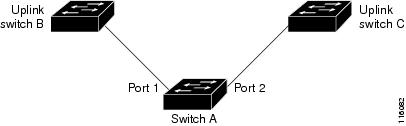
In the following figure, ports 1 and 2 on switch A are connected to uplink switches B and C. Because they are configured with
FlexLink+, only one of the interfaces is forwarding traffic; the other is in standby mode. If port 1 is the active link, it
begins forwarding traffic between port 1 and switch B; the link between port 2 (the backup link) and switch C is not forwarding
traffic. If port 1 goes down, port 2 comes up and starts forwarding traffic to switch C. When port 1 comes back up, it goes
into standby mode and does not forward traffic; port 2 continues forwarding traffic.
Figure 1. FlexLink+ Topology
If STP is configured on the uplink switch interfaces that connect to the FlexLink+ ports (Switch B and Switch C in this case),
we recommend running the spanning-tree portfast trunk command on such uplink switch interfaces, for faster convergence.
Flexlink+ includes an optimization for improved multicast traffic convergence. The optimization uses Layer 2 multicast snooping
mechanisms and requires that the uplink switches connected to the Flexlink+ configured ports have the same Layer 2 multicast
snooping feature enabled.
Note
For IPv4 multicast IGMP snooping is on by default. If IGMP snooping needs to be disabled on the uplink switches it must also
be disabled on the Flexlink+ host switch. Otherwise IGMP reports may be looped around the active and standby Flexlink+ ports
leading to excessively high CPU utilization.
How to configure Flexlink+
The following sections provide information on how to configure Flexlink+.
Configuring the active port for FlexLink+
Procedure
Command or Action
Purpose
Step 1
enable
Example:
Device> enable
Enables privileged EXEC mode. Enter your password if prompted.
Step 2
configureterminal
Example:
Device# configure terminal
Enters global configuration mode.
Step 3
interface interface-id
Example:
Device# interface Port-channel2
Specifies the interface, and enters interface configuration mode.
This table provides release and related information for features explained in this module.
These features are available on all releases subsequent to the one they were introduced in, unless noted otherwise.
Release
Feature
Feature Information
Cisco IOS XE Gibraltar 16.12.1
FlexLink+
The FlexLink+ feature enables the user to configure a pair of a Layer 2 interfaces (trunk ports or port channels) where one
interface is configured to act as a backup to the other interface.
Cisco IOS XE Amsterdam 17.2.1
VLAN Load Balancing for FlexLink+
Preemption for VLAN Load Balancing
FlexLink+ Dummy Multicast Packets
VLAN load balancing feature was introduced on FlexLink+. VLAN load-balancing allows you to configure a FlexLink+ pair so that
both ports can simultaneously forward the traffic for some mutually exclusive VLANs.
You can trigger VLAN load balancing either by manually triggering it or by configuring a preempt delay.
When a primary link fails, FlexLink+ transmits dummy multicast packets over the new active interface. These packets help learn
the source MAC address.
Use Cisco Feature Navigator to find information about platform and software image support. To access Cisco Feature Navigator,
go to http://www.cisco.com/go/cfn.

 Feedback