Configuring Ethernet-over-MPLS
This section provides information about how to configure Ethernet over Multiprotocol Label Switching (EoMPLS).
Information About EoMPLS
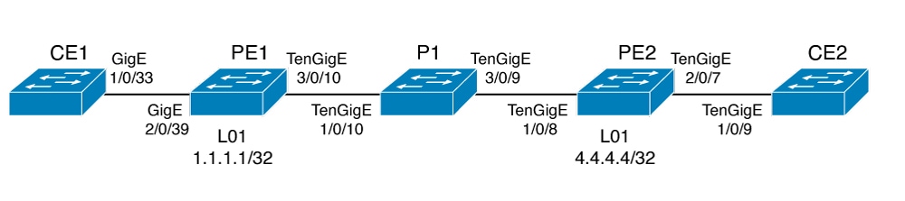
EoMPLS is one of the Any Transport over MPLS (AToM) transport types. EoMPLS works by encapsulating Ethernet protocol data units (PDUs) in MPLS packets and forwarding them across the MPLS network. Each PDU is transported as a single packet.
Only the following mode is supported:
-
Port mode—Allows all traffic on a port to share a single virtual circuit across an MPLS network. Port mode uses virtual circuit type 5.
Prerequisites for Ethernet-over-MPLS
Before you configure EoMPLS, ensure that the network is configured as follows:
-
Configure IP routing in the core so that the provider edge (PE) devices can reach each other through IP.
-
Configure MPLS in the core so that a label switched path (LSP) exists between the PE devices.
-
Configure the no switchport , no keepalive , and no ip address commands before configuring Xconnect on the attachment circuit.
-
For load-balancing, configuring the port-channel load-balance command is mandatory.
-
Subinterfaces must be supported to enable EoMPLS VLAN mode.
-
The mpls ldp graceful-restart command must be configured to enable the device to protect LDP bindings and MPLS forwarding state during a disruption in service. We recommend you to configure this command (even if you do not want to preserve the forwarding state) to avoid device failure during SSO in a high availability setup with scale configurations.
Restrictions for EoMPLS
-
VLAN mode is not supported. Ethernet Flow Point is not supported.
-
QoS : Customer DSCP Re-marking is not supported with VPWS and EoMPLS.
-
VCCV Ping with explicit null is not supported.
-
L2 VPN Interworking is not supported.
-
L2 Protocol Tunneling CLI is not supported.
-
Untagged, tagged and 802.1Q in 802.1Q are supported as incoming traffic.

Note
Flow Load balance for 802.1Q in 802.1Q over EoMPLS is not supported.
-
Flow Aware Transport Pseudowire Redundancy (FAT PW) is supported only in Protocol-CLI mode. Supported load balancing parameters are Source IP, Source MAC address, Destination IP and Destination MAC address.
-
Enabling or disabling Control word is supported.
-
MPLS QoS is supported in Pipe and Uniform Mode. Default mode is Pipe Mode.
-
Both – the legacy xconnect and Protocol-CLI (interface pseudowire configuration) modes are supported.
-
Xconnect and MACSec cannot be configured on the same interface.
-
MACSec should be configured on CE devices and Xconnect should be configured on PE devices.
-
A MACSec session should be between CE devices.
-
By default, EoMPLS PW tunnels all protocols like CDP, STP. EoMPLS PW cannot perform selective protocol tunneling as part of L2 Protocol Tunneling CLI.
Configuring Port-Mode EoMPLS
Port-Mode EoMPLS can be configured in two modes :
-
Xconnect Mode
-
Protocol CLI Method
Xconnect Mode
To configure EoMPLS port mode in Xconnect mode, perform the following task:
Procedure
| Command or Action | Purpose | |
|---|---|---|
|
Step 1 |
enable Example: |
Enables privileged EXEC mode. Enter your password if prompted. |
|
Step 2 |
configure terminal Example: |
Enters global configuration mode. |
|
Step 3 |
interface interface-id Example: |
Defines the interface to be configured as a trunk, and enters interface configuration mode. |
|
Step 4 |
no switchport Example: |
Enters Layer 3 mode for physical ports only. |
|
Step 5 |
no ip address Example: |
Ensures that no IP address is assigned to the physical port. |
|
Step 6 |
no keepalive Example: |
Ensures that the device does not send keepalive messages. |
|
Step 7 |
xconnect peer-device-id vc-id encapsulation mpls Example: |
Binds the attachment circuit to a pseudowire virtual circuit (VC). The syntax for this command is the same as for all other Layer 2 transports. |
|
Step 8 |
end Example: |
Exits interface configuration mode and returns to privileged EXEC mode. |
Protocol CLI Method
To configure EoMPLS port mode in protocol CLI mode, perform the following task:
Procedure
| Command or Action | Purpose | |
|---|---|---|
|
Step 1 |
enable Example: |
Enables privileged EXEC mode. Enter your password if prompted. |
|
Step 2 |
configure terminal Example: |
Enters global configuration mode. |
|
Step 3 |
port-channel load-balance dst-ip Example: |
Sets the load distribution method to the destination IP address. |
|
Step 4 |
interface interface-id Example: |
Defines the interface to be configured as a trunk, and enters interface configuration mode. |
|
Step 5 |
no switchport Example: |
Enters Layer 3 mode for physical ports only. |
|
Step 6 |
no ip address Example: |
Ensures that no IP address is assigned to the physical port. |
|
Step 7 |
no keepalive Example: |
Ensures that the device does not send keepalive messages. |
|
Step 8 |
exit Example: |
Exits interface configuration mode and returns to global configuration mode. |
|
Step 9 |
interface pseudowire number Example: |
Establishes a pseudowire interface with a value that you specify and enters pseudowire configuration mode. |
|
Step 10 |
encapsulation mpls Example: |
Specifies the tunneling encapsulation. |
|
Step 11 |
neighbor peer-ip-addr vc-id Example: |
Specifies the peer IP address and virtual circuit (VC) ID value of a Layer 2 VPN (L2VPN) pseudowire. |
|
Step 12 |
l2vpn xconnect context context-name Example: |
Creates an L2VPN cross connect context and enters Xconnect context configuration mode. |
|
Step 13 |
member interface-id Example: |
Specifies interface that forms an L2VPN cross connect. |
|
Step 14 |
member pseudowire number Example: |
Specifies the pseudowire interface that forms an L2VPN cross connect. |
|
Step 15 |
end Example: |
Exits Xconnect interface configuration mode and returns to privileged EXEC mode. |
Configuration Examples for EoMPLS
|
PE Configuration |
CE Configuration |
|---|---|
|
|
Local interface: Gi1/0/1 up, line protocol up, Ethernet up
 Destination address: 1.1.1.1, VC ID: 101, VC status: up
Output interface: Vl182, imposed label stack {17 16}
Preferred path: not configured
Default path: active
Next hop: 182.1.1.1
Load Balance: ECMP
flow classification: ip dst-ip
Create time: 06:22:11, last status change time: 05:58:42
Last label FSM state change time: 05:58:42  Signaling protocol:
LDP, peer 1.1.1.1:0 up
Targeted Hello: 4.4.4.4(LDP Id) -> 1.1.1.1, LDP is UP
Graceful restart: not configured and not enabled
Non stop routing: not configured and not enabled
Status TLV support (local/remote)   : enabled/supported
LDP route watch                   : enabled
Label/status state machine        : established, LruRru
Last local dataplane   status rcvd: No fault
Last BFD dataplane     status rcvd: Not sent
Last BFD peer monitor  status rcvd: No fault
Last local AC  circuit status rcvd: No fault
Last local AC  circuit status sent: No fault
Last local PW i/f circ status rcvd: No fault
Last local LDP TLV     status sent: No fault
Last remote LDP TLV    status rcvd: No fault
Last remote LDP ADJ    status rcvd: No fault
MPLS VC labels: local 512, remote 16
Group ID: local n/a, remote 0
MTU: local 9198, remote 9198
Remote interface description:   Sequencing: receive disabled, send disabled
Control Word: On (configured: autosense)
SSO Descriptor: 1.1.1.1/101, local label: 512
Dataplane:
SSM segment/switch IDs: 4096/4096 (used), PWID: 1
VC statistics:    transit packet totals: receive 172116845, send 172105364
transit byte totals:   receive 176837217071, send 172103349728
 transit packet drops:  receive 0, seq error 0, send 0
The following is a sample output of show l2vpn atom vc vcid vc-id detail command:
pseudowire101 is up, VC status is up PW type: Ethernet
Create time: 06:30:41, last status change time: 06:07:12
Last label FSM state change time: 06:07:12
Destination address: 1.1.1.1 VC ID: 101
Output interface: Vl182, imposed label stack {17 16}
 Preferred path: not configured
 Default path: active    Next hop: 182.1.1.1
Load Balance: ECMP  Flow classification: ip dst-ip
Member of xconnect service pw101
Associated member Gi1/0/1 is up, status is up
Interworking type is Like2Like    Service id: 0xe5000001
Signaling protocol: LDP, peer 1.1.1.1:0 up
Targeted Hello: 4.4.4.4(LDP Id) -> 1.1.1.1, LDP is UP
Graceful restart: not configured and not enabled
Non stop routing: not configured and not enabled
PWid FEC (128), VC ID: 101    Status TLV support (local/remote)         : enabled/supported
 LDP route watch                         : enabled
Label/status state machine              : established, LruRru
Local dataplane status received         : No fault
BFD dataplane status received           : Not sent
BFD peer monitor status received        : No fault
Status received from access circuit     : No fault
Status sent to access circuit           : No fault
Status received from pseudowire i/f     : No fault
Status sent to network peer             : No fault
Status received from network peer       : No fault
Adjacency status of remote peer         : No fault
Sequencing: receive disabled, send disabled  Bindings
 Parameter    Local                          Remote
------------ ------------------------------ ------------------------------
Label        512                            16
Group ID     n/a                            0
Interface
MTU          9198                           9198
Control word on (configured: autosense)     on
PW type      Ethernet                       Ethernet
VCCV CV type 0x02                           0x02
                   LSPV [2]                       LSPV [2]
VCCV CC type 0x06                           0x06
                   RA [2], TTL [3]               RA [2], TTL [3]
Status TLV   enabled                        supported
Flow Label   T=1, R=1                       T=1, R=1
SSO Descriptor: 1.1.1.1/101, local label: 512
Dataplane:
SSM segment/switch IDs: 4096/4096 (used), PWID: 1
Rx Counters    176196691 input transit packets, 181028952597 bytes
 0 drops, 0 seq err
Tx Counters    176184928 output transit packets, 176182865992 bytes
0 drops
The following is a sample output of show mpls forwarding-table command:
Local      Outgoing   Prefix           Bytes Label   Outgoing   Next Hop
Label      Label      or Tunnel Id     Switched      interface
57         18         1.1.1.1/32       0             Po45       145.1.1.1
           No Label   1.1.1.1/32       0             Te1/0/2    147.1.1.1
           No Label   1.1.1.1/32       0             Te1/0/11   149.1.1.1
No Label 1.1.1.1/32 0 Te1/0/40 155.1.1.1  Feedback