-
null
VLAN Trunking Protocol (VTP)
- Prerequisites for VTP
- Restrictions for VTP
- Information About VTP
- Default Settings for VTP
- How to Configure VTP

Note ●![]() For complete syntax and usage information for the commands used in this chapter, see these publications:
For complete syntax and usage information for the commands used in this chapter, see these publications:
http://www.cisco.com/en/US/products/ps11846/prod_command_reference_list.html
- Cisco IOS Release 15.4SY supports only Ethernet interfaces. Cisco IOS Release 15.4SY does not support any WAN features or commands.
http://www.cisco.com/en/US/products/hw/switches/ps708/tsd_products_support_series_home.html
Participate in the Technical Documentation Ideas forum
Prerequisites for VTP
Restrictions for VTP
- Supervisor engine redundancy does not support nondefault VLAN data filenames or locations. Do not enter the vtp file file_name command on a switch that has a redundant supervisor engine.
- Before installing a redundant supervisor engine, enter the no vtp file command to return to the default configuration.
- All network devices in a VTP domain must run the same VTP version.
- You must configure a password on each network device in the management domain when in secure mode.

- A VTP version 2-capable network device can operate in the same VTP domain as a network device that runs VTP version 1 if VTP version 2 is disabled on the VTP version 2-capable network device (VTP version 2 is disabled by default).
- Do not enable VTP version 2 on a network device unless all of the network devices in the same VTP domain are version 2-capable. When you enable VTP version 2 on a network device, all of the version 2-capable network devices in the domain enable VTP version 2.
- In a Token Ring environment, you must enable VTP version 2 for Token Ring VLAN switching to function properly.
- When you enable or disable VTP pruning on a VTP server, VTP pruning for the entire management domain is enabled or disabled.
- The pruning-eligibility configuration applies globally to all trunks on the switch. You cannot configure pruning eligibility separately for each trunk.
- When you configure VLANs as pruning eligible or pruning ineligible, pruning eligibility for those VLANs is affected on that switch only, not on all network devices in the VTP domain.
- VTP version 1 and VTP version 2 do not propagate configuration information for extended-range VLANs (VLAN numbers 1006 to 4094). You must configure extended-range VLANs manually on each network device.
- VTP version 3 supports extended-range VLANs (VLAN numbers 1006 to 4094). If you convert from VTP version 3 to VTP version 2, the VLANs in the range 1006 to 4094 are removed from VTP control.
- VTP version 3 supports propagation of any database in a domain by allowing you to configure a primary and secondary server.
- The network administrator has to manually configure VTP version 3 on the switches that need to run VTP version 3.
- VTP version 3 is not supported on private VLAN (PVLAN) ports.
- Prior to configuring VTP version 3, you must ensure that the spanning-tree extend system-id command has been enabled.
- If there is insufficient DRAM available for use by VTP, the VTP mode changes to transparent.
- Network devices in VTP transparent mode do not send VTP Join messages. On trunk connections to network devices in VTP transparent mode, configure the VLANs that are used by the transparent-mode network devices or that need to be carried across trunks as pruning ineligible. For information about configuring prune eligibility, see the “Configuring the List of Prune-Eligible VLANs” section.
Information About VTP
- VTP Overview
- VTP Domains
- VTP Modes
- VTP Advertisements
- VTP Authentication
- VTP Version 2
- VTP Version 3
- VTP Pruning
- VLAN Interaction
Note![]() For complete information on configuring VLANs, see Chapter26, “Virtual Local Area Networks (VLANs)”
For complete information on configuring VLANs, see Chapter26, “Virtual Local Area Networks (VLANs)”
VTP Overview
VTP is a Layer 2 messaging protocol that maintains VLAN configuration consistency by managing the addition, deletion, and renaming of VLANs within a VTP domain. A VTP domain (also called a VLAN management domain) is made up of one or more network devices that share the same VTP domain name and that are interconnected with trunks. VTP minimizes misconfigurations and configuration inconsistencies that can result in a number of problems, such as duplicate VLAN names, incorrect VLAN-type specifications, and security violations. Before you create VLANs, you must decide whether to use VTP in your network. With VTP, you can make configuration changes centrally on one or more network devices and have those changes automatically communicated to all the other network devices in the network.
VTP Domains
A VTP domain (also called a VLAN management domain) is made up of one or more interconnected network devices that share the same VTP domain name. A network device can be configured to be in one and only one VTP domain. You make global VLAN configuration changes for the domain using either the command-line interface (CLI) or Simple Network Management Protocol (SNMP).
VTP server mode is the default and the switch is in the no-management domain state until it receives an advertisement for a domain over a trunk link or you configure a management domain.
If the switch receives a VTP advertisement over a trunk link, it inherits the management domain name and the VTP configuration revision number. The switch ignores advertisements with a different management domain name or an earlier configuration revision number.
If you configure the switch as VTP transparent, you can create and modify VLANs but the changes affect only the individual switch. The valid VLAN ranges are as follows:
- VTP version 1 and version 2 support VLANs 1 to 1000 only.
- VTP version 3 supports the entire VLAN range (VLANs 1 to 4094).
- The pruning of VLANs still applies to VLANs 1 to 1000 only.
- Extended-range VLANs are supported only in VTP version 3. If converting from VTP version 3 to VTP version 2, VLANs in the range 1006 to 4094 are removed from VTP control.
By default, all devices come up as secondary servers. You can enter the vtp primary privileged EXEC mode command to specify a primary server.
When using VTP version 1 and version 2, a VTP server is used to back up the database to the NVRAM and allows you to change the database information.
In VTP version 3, there is a VTP-primary server and a VTP-secondary server. A primary server allows you to alter the database information and the database updates sent out are honored by all the devices in the system. A secondary server can only back up the updated VTP configuration received from the primary server in the NVRAMs. The status of the primary and secondary servers is a runtime status and is not configurable.
VTP maps VLANs dynamically across multiple LAN types with unique names and internal index associations. Mapping eliminates excessive device administration required from network administrators.
VTP Modes
You can configure any one of these VTP modes:
- Server—In VTP server mode, you can create, modify, and delete VLANs and specify other configuration parameters (such as VTP version and VTP pruning) for the entire VTP domain. VTP servers advertise their VLAN configuration to other network devices in the same VTP domain and synchronize their VLAN configuration with other network devices based on advertisements received over trunk links. VTP server is the default mode.
- Client—VTP clients behave the same way as VTP servers, but you cannot create, change, or delete VLANs on a VTP client.
- Transparent—VTP transparent network devices do not participate in VTP. A VTP transparent network device does not advertise its VLAN configuration and does not synchronize its VLAN configuration based on received advertisements. However, in VTP version 2, a transparent network device will forward received VTP advertisements from its trunking LAN ports. In VTP version 3, a transparent network device is specific to an instance.
- Off—In VTP off mode, a network device functions in the same manner as a VTP transparent device except that it does not forward VTP advertisements.
Note![]() The VTP server mode automatically changes from VTP server mode to VTP client mode if the switch detects a failure while writing configuration to NVRAM. If this happens, the switch cannot be returned to VTP server mode until the NVRAM is functioning.
The VTP server mode automatically changes from VTP server mode to VTP client mode if the switch detects a failure while writing configuration to NVRAM. If this happens, the switch cannot be returned to VTP server mode until the NVRAM is functioning.
VTP Advertisements
Each network device in the VTP domain sends periodic advertisements out each trunking LAN port to a reserved multicast address. VTP advertisements are received by neighboring network devices, which update their VTP and VLAN configurations as necessary.
The following global configuration information is distributed in VTP version 1 and version 2 advertisements:
- VLAN IDs.
- Emulated LAN names (for ATM LANE).
- 802.10 SAID values (FDDI).
- VTP domain name.
- VTP configuration revision number.
- VLAN configuration, including the maximum transmission unit (MTU) size for each VLAN.
- Frame format.
In VTP version 3, the information distributed in VTP version 1 and version 2 advertisements are supported, as well as the following information:
- A primary server ID.
- An instance number.
- A start index.
- An advertisement request is sent by a Client or a Server in these situations:
–![]() On a trunk coming up on a switch with an invalid database.
On a trunk coming up on a switch with an invalid database.
–![]() On all trunks when the database of a switch becomes invalid as a result of a configuration change or a takeover message.
On all trunks when the database of a switch becomes invalid as a result of a configuration change or a takeover message.
–![]() On a specific trunk where a superior database has been advertised.
On a specific trunk where a superior database has been advertised.
VTP Authentication
When VTP authentication is not configured, the secret that is used to validate the received VTP updates is visible in plain text in the show commands and the NVRAM file, const_nvram:vlan.dat. In the event that a device in a VTP domain is compromised, the administrator must change the VTP secret across all the devices in the VTP domain.
With VTP version 3, you can configure the authentication password to be hidden using the vtp password command. When you configure the authentication password to be hidden, it does not appear in plain text in the configuration. Instead, the secret associated with the password is saved in hexadecimal format in the running configuration. The password - string argument is an ASCII string from 8 to 64 characters identifying the administrative domain for the device.
VTP Version 2
VTP version 2 supports the following features not supported in version 1:
- Token Ring support—VTP version 2 supports Token Ring LAN switching and VLANs (Token Ring Bridge Relay Function [TrBRF] and Token Ring Concentrator Relay Function [TrCRF]). For more information about Token Ring VLANs, see the “Information About VLANs” section.
- Unrecognized Type-Length-Value (TLV) Support—A VTP server or client propagates configuration changes to its other trunks, even for TLVs that it is not able to parse. The unrecognized TLV is saved in NVRAM.
- Version-Dependent Transparent Mode—In VTP version 1, a VTP transparent network device inspects VTP messages for the domain name and version and forwards a message only if the version and domain name match. Because only one domain is supported, VTP version 2 forwards VTP messages in transparent mode without checking the version.
- Consistency Checks—In VTP version 2, VLAN consistency checks (such as VLAN names and values) are performed only when you enter new information through the CLI or SNMP. Consistency checks are not performed when new information is obtained from a VTP message, or when information is read from NVRAM. If the digest on a received VTP message is correct, its information is accepted without consistency checks.
VTP Version 3
VTP version 3 supports all the features in version 1 and version 2. VTP version 3 also supports the following features not supported in version 1 and version 2:
- Enhanced authentication—In VTP version 3, you can configure the authentication password to be hidden using the vtp password command. When you configure the authentication password to be hidden, it does not appear in plain text in the configuration. Instead, the secret associated with the password is saved in hexadecimal format in the running configuration. The password - string argument is an ASCII string from 8 to 64 characters identifying the administrative domain for the device.
The hidden and secret keywords for VTP password are supported only in VTP version 3. If converting to VTP version 2 from VTP version 3, you must remove the hidden or secret keyword prior to the conversion.
- Support for extended range VLAN database propagation—VTP version 1 and version 2 support VLANs 1 to 1000 only. In VTP version 3, the entire VLAN range is supported (VLANs 1 to 4094). The pruning of VLANs still applies to VLANs 1 to 1000 only. Extended-range VLANs are supported in VTP version 3 only. Private VLANs are supported in VTP version 3. If you convert from VTP version 3 to VTP version 2, the VLANs in the range 1006 to 4094 are removed from VTP control.
- VLANs 1002 to 1005 are reserved VLANs in VTP version 1, version 2, and version 3.
- Support for propagation of any database in a domain—In VTP version 1 and version 2, a VTP server is used to back up the database to the NVRAM and allows you to change the database information.
Note![]() VTP version 3 supports Multiple Spanning Tree (802.1s) (MST) database propagation separate from the VLAN database only. In the MST database propagation, there is a VTP primary server and a VTP econdary server. A primary server allows you to alter the database information, and the database updates sent out are honored by all the devices in the system. A secondary server can only back up the updated VTP configuration received from the primary server in the NVRAMs. The status of the primary and secondary servers is a runtime status and is not configurable.
VTP version 3 supports Multiple Spanning Tree (802.1s) (MST) database propagation separate from the VLAN database only. In the MST database propagation, there is a VTP primary server and a VTP econdary server. A primary server allows you to alter the database information, and the database updates sent out are honored by all the devices in the system. A secondary server can only back up the updated VTP configuration received from the primary server in the NVRAMs. The status of the primary and secondary servers is a runtime status and is not configurable.
By default, all devices come up as secondary servers. You can enter the vtp primary privileged EXEC mode command to specify a primary server.
The primary-server status is needed only when database changes have to be performed and is obtained when the administrator issues a takeover message in the domain. The primary-server status is lost when you reload, switch over, or the domain parameters change. The secondary servers back up the configuration and continue to propagate the database. You can have a working VTP domain without any primary servers. Primary and secondary servers may exist on an instance in the domain.
In VTP version 3, there is no longer a restriction to propagate only VLAN database information. You can use VTP version 3 to propagate any database information across the VTP domain. A separate instance of the protocol is running for each application that uses VTP.
Two VTP version 3 regions can only communicate over a VTP version 1 or VTP version 2 region in transparent mode.
- CLI to turn off/on VTP on a per-trunk basis—You can enable VTP on a per-trunk basis using the vtp interface configuration mode command. You can disable VTP on a per-trunk basis using the no form of this command. When you disable VTP on the trunking port, all the VTP instances for that port are disabled. You will not be provided with the option of setting VTP to OFF for the MST database and ON for the VLAN database.
VTP on a global basis—When you set VTP mode to OFF globally, this applies to all the trunking ports in the system. Unlike the per-port configuration, you can specify the OFF option on a per-VTP instance basis. For example, the system could be configured as VTP-server for the VLAN database and as VTP-off for the MST database. In this case, VLAN databases are propagated by VTP, MST updates are sent out on the trunk ports in the system, and the MST updates received by the system are discarded.
VTP Pruning
VTP pruning enhances network bandwidth use by reducing unnecessary flooded traffic, such as broadcast, multicast, unknown, and flooded unicast packets. VTP pruning increases available bandwidth by restricting flooded traffic to those trunk links that the traffic must use to access the appropriate network devices. By default, VTP pruning is disabled.
In VTP versions 1 and 2, when you enable or disable pruning, it is propagated to the entire domain and accepted by all the devices in that domain. In VTP version 3, the domain administrator must manually enable or disable VTP pruning explicitly on each device.
For VTP pruning to be effective, all devices in the management domain must support VTP pruning. On devices that do not support VTP pruning, you must manually configure the VLANs allowed on trunks.
Figure 25-1 shows a switched network without VTP pruning enabled. Interface 1 on network Switch 1 and port 2 on Switch 4 are assigned to the Red VLAN. A broadcast is sent from the host connected to Switch 1. Switch 1 floods the broadcast, and every network device in the network receives it, even though Switches 3, 5, and 6 have no ports in the Red VLAN.
You enable pruning globally on the switch (see the “Enabling VTP Pruning” section). You configure pruning on Layer 2 trunking LAN ports (see the “Configuring a Layer 2 Switching Port as a Trunk” section).
Figure 25-1 Flooding Traffic without VTP Pruning
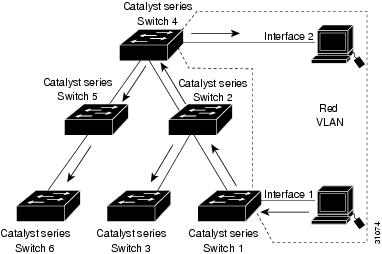
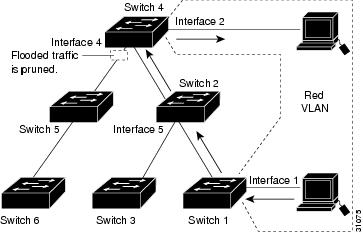
Figure 25-2 shows the same switched network with VTP pruning enabled. The broadcast traffic from Switch 1 is not forwarded to Switches 3, 5, and 6 because traffic for the Red VLAN has been pruned on the links indicated (port 5 on Switch 2 and port 4 on Switch 4).
Figure 25-2 Flooding Traffic with VTP Pruning
Enabling VTP pruning on a VTP server enables pruning for the entire management domain. VTP pruning takes effect several seconds after you enable it. By default, VLANs 2 through 1000 are pruning eligible. VTP pruning does not prune traffic from pruning-ineligible VLANs. VLAN 1 is always pruning ineligible; traffic from VLAN 1 cannot be pruned.
To configure VTP pruning on a trunking LAN port, use the switchport trunk pruning vlan command (see the “Configuring a Layer 2 Switching Port as a Trunk” section). VTP pruning operates when a LAN port is trunking. You can set VLAN pruning eligibility when VTP pruning is enabled or disabled for the VTP domain, when any given VLAN exists or not, and when the LAN port is currently trunking or not.
VLAN Interaction
This section describes the VLAN interaction between devices with different VTP versions:
Interaction Between VTP Version 3 and VTP Version 2 Devices
When a VTP version 3 device on a trunk port receives messages from a VTP version 2 device, the VTP version 3 device sends a scaled-down version of the VLAN database on that particular trunk in a VTP version 2 format. A VTP version 3 device does not send out VTP version 2-formatted packets on a trunk port unless it first receives VTP version 2 packets on that trunk. If the VTP version 3 device does not receive VTP version 2 packets for an interval of time on the trunk port, the VTP version 3 device stops transmitting VTP version 2 packets on that trunk port.
Even when a VTP version 3 device detects a VTP version 2 device on a trunk port, the VTP version 3 device continues to send VTP version 3 packets in addition to VTP version 3 device 2 packets, to allow two kinds of neighbors to coexist on the trunk. VTP version 3 sends VTP version 3 and VTP version 2 updates on VTP version 2-detected trunks.
A VTP version 3 device does not accept configuration from a VTP version 2 (or VTP version 1) device.
Unlike in VTP version 2, when you configure the VTP version to be version 3, version 3 does not configure all the VTP version 3-capable devices in the domain to start behaving as VTP version 3 systems.
Interaction Between VTP Version 3 and VTP Version 1 Devices
When a VTP version 1 device that is capable of VTP version 2 or VTP version 3 receives a VTP version 3 packet, it will be configured as a VTP version 2 device if VTP version 2 conflicts do not exist.
VTP version 1-only capable devices cannot interoperate with VTP version 3 devices.
Default Settings for VTP
How to Configure VTP
- Configuring VTP Global Parameters
- Configuring the VTP Mode
- Configuring VTP Mode on a Per-Port Basis
- Displaying VTP Statistics
Configuring VTP Global Parameters
- Configuring VTP Version 1 and Version 2 Passwords
- Configuring VTP Version 3 Password
- Enabling VTP Pruning
- Enabling VTP Version 2
- Enabling VTP Version 3
Note![]() You can enter the VTP global parameters in either global configuration mode or in EXEC mode.
You can enter the VTP global parameters in either global configuration mode or in EXEC mode.
Configuring VTP Version 1 and Version 2 Passwords
To configure the VTP version 1 and version 2 global parameters, perform this task:
|
|
|
|---|---|
Sets a password, which can be from 8 to 64 characters long, for the VTP domain. |
|
This example shows one way to configure a VTP password in global configuration mode:
This example shows how to configure a VTP password in EXEC mode:
Note![]() The password is not stored in the running-config file.
The password is not stored in the running-config file.
Configuring VTP Version 3 Password
To configure the VTP version 3 password, perform this task:
This example shows one way to configure a VTP password in global configuration mode:
Note![]() If you configure a VTP password in EXEC mode, the password is not stored in the running-config file.
If you configure a VTP password in EXEC mode, the password is not stored in the running-config file.
This example shows one way to configure the password with a hidden key saved in hexadecimal format in the running configuration :
This example shows how you configure the password secret key in hexadecimal format:
Configuring VTP Version 3 Server Type
To specify a primary server, perform this task:
|
|
|
|---|---|
The vtp primary command does not have a no form. To return to the secondary server status, one of the following conditions must be met:
- System reload.
- Switchover between redundant supervisors.
- Takeover from another server.
- Change in the mode configuration.
- Any domain configuration change (version, domain name, domain password).
This example shows how to configure this device as the primary server if the password feature is disabled:
This example shows how to configure this device as the primary server for the VTP VLAN feature if the password feature is disabled:
This example shows how to force this device to be the primary server for the VTP MST feature if the password feature is disabled :
This example shows how to force this device to be the primary server for the VTP MST feature when the domain VTP password is set with the hidden or secret keyword:
Enabling VTP Pruning
To enable VTP pruning in the management domain, perform this task:
|
|
|
|---|---|
This example shows one way to enable VTP pruning in the management domain:
This example shows how to enable VTP pruning in the management domain with any release:
This example shows how to verify the configuration:
For information about configuring prune eligibility, see the “Configuring the List of Prune-Eligible VLANs” section.
Enabling VTP Version 2
VTP version 2 is disabled by default on VTP version 2-capable network devices. When you enable VTP
version 2 on a network device, every VTP version 2-capable network device in the VTP domain enables version 2.
Note![]() In a Token Ring environment, you must enable VTP version 2 for Token Ring VLAN switching to function properly on devices that support Token Ring interfaces.
In a Token Ring environment, you must enable VTP version 2 for Token Ring VLAN switching to function properly on devices that support Token Ring interfaces.
To enable VTP version 2, perform this task:
|
|
|
|---|---|
This example shows one way to enable VTP version 2:
This example shows how to enable VTP version 2 with any release:
This example shows how to verify the configuration:
Enabling VTP Version 3
VTP version 3 is disabled by default. You can enable version 3 in global configuration mode only. The network administrator has to manually configure VTP version 3 on the switches that need to run VTP version 3.
Note![]() Prior to configuring VTP version 3, you must ensure that the spanning-tree extend system-id command has been enabled.
Prior to configuring VTP version 3, you must ensure that the spanning-tree extend system-id command has been enabled.
To enable VTP version 3, perform this task:
|
|
|
|---|---|
This example shows one way to enable VTP version 3:
This example shows how to verify the configuration:
Configuring the VTP Mode
To configure the VTP mode, perform this task:
Note![]() When VTP is disabled, you can enter VLAN configuration commands in configuration mode instead of the VLAN database mode and the VLAN configuration is stored in the startup configuration file.
When VTP is disabled, you can enter VLAN configuration commands in configuration mode instead of the VLAN database mode and the VLAN configuration is stored in the startup configuration file.
This example shows how to configure the switch as a VTP server:
This example shows how to configure the switch as a VTP client:
This example shows how to disable VTP on the switch:
This example shows how to disable VTP on the switch and to disable VTP advertisement forwarding:
This example shows how to verify the configuration:
Configuring VTP Mode on a Per-Port Basis
You can configure VTP mode on a per-port basis. The VTP enable value will be applied only when a port becomes switched port in trunk mode. Incoming and outgoing vtp pdus are blocked; not forwarded. In VTP version 3, you can also configure VTP mode on a per-trunk basis. To configure VTP mode, perform this task:
|
|
|
|
|---|---|---|
This example shows how to configure VTP mode on a port:
This example shows how to disable VTP mode on a port:
This example shows how to verify the configuration change:
This example shows how to verify the interface:
Displaying VTP Statistics
To display VTP statistics, including VTP advertisements sent and received and VTP errors, perform this task:
|
|
|
|---|---|
This example shows how to display VTP statistics:
http://www.cisco.com/en/US/products/hw/switches/ps708/tsd_products_support_series_home.html
Participate in the Technical Documentation Ideas forum
 Feedback