-
null
- About ACLs
- Hardware and Software ACL Support
- Troubleshooting High CPU Due to ACLs
- Selecting Mode of Capturing Control Packets
- Creating a PACL
- PACL Configuration Guidelines
- Removing the Requirement for a Port ACL
- Webauth Fallback
- Configuring IPv4, IPv6, and MAC ACLs on a Layer 2 Interface
- Using PACL with Access-Group Mode
- Configuring Access-group Mode on Layer 2 Interface
- Applying ACLs to a Layer 2 Interface
- Displaying an ACL Configuration on a Layer 2 Interface
Configuring Network Security with ACLs
This chapter describes how to use access control lists (ACLs) to configure network security on the Catalyst 4500 series switches.

Note![]() Catalyst 4500 series switches supports time-based ACLs.
Catalyst 4500 series switches supports time-based ACLs.
This chapter consists of the following major sections:
- About ACLs
- Hardware and Software ACL Support
- Troubleshooting High CPU Due to ACLs
- TCAM Programming and ACLs
- Layer 4 Operators in ACLs
- Configuring Unicast MAC Address Filtering
- Configuring Named MAC Extended ACLs
- Configuring EtherType Matching
- Configuring Named IPv6 ACLs
- Applying IPv6 ACLs to Layer 2 and 3 Interface
- Configuring VLAN Maps
- Displaying VLAN Access Map Information
- Using VLAN Maps with Router ACLs
- Configuring PACLs
- Using PACL with VLAN Maps and Router ACLs
- Configuring Object Group ACLs
- Configuring RA Guard
Note![]() For complete syntax and usage information for the switch commands used in this chapter, see the
For complete syntax and usage information for the switch commands used in this chapter, see the
Cisco IOS Command Reference Guides for the Catalyst 4500 Series Switch.
If a command is not in the Cisco Catalyst 4500 Series Switch Command Reference , you can locate it in the Cisco IOS Master Command List, All Releases.
About ACLs
This section includes these topics:
Overview
An ACL is a collection of sequential permit and deny conditions that applies to packets. When a packet is received on an interface, the switch compares the fields in the packet against any applied ACLs to verify that the packet has the permissions required to be forwarded, based on the conditions specified in the access lists. It tests the packets against the conditions in an access list one-by-one. The first match determines whether the switch accepts or rejects the packets. Because the switch stops testing conditions after the first match, the order of conditions in the list is critical. If no conditions match, the switch drops the packet. If no restrictions exist, the switch forwards the packet; otherwise, the switch drops the packet.
Switches traditionally operate at Layer 2, switching traffic within a VLAN. Routers route traffic between VLANs at Layer 3. The Catalyst 4500 series switch can accelerate packet routing between VLANs by using Layer 3 switching. The Layer 3 switch bridges the packet, and then routes the packet internally without going to an external router. The packet is then bridged again and sent to its destination. During this process, the switch can control all packets, including packets bridged within a VLAN.
You configure access lists on a router or switch to filter traffic and provide basic security for your network. If you do not configure ACLs, all packets passing using the switch could be allowed on all parts of the network. You can use ACLs to control which hosts can access different parts of a network or to decide which types of traffic are forwarded or blocked at router interfaces. For example, you can allow e-mail traffic to be forwarded but not Telnet traffic. ACLs can be configured to block inbound traffic, outbound traffic, or both. However, on Layer 2 interfaces, you can apply ACLs only in the inbound direction.
An ACL contains an ordered list of access control entries (ACEs). Each ACE specifies permit or deny and a set of conditions the packet must satisfy in order to match the ACE. The meaning of permit or deny depends on the context in which the ACL is used. Negative TCP flags such as -syn, -psh or -fin in ACEs are not considered when you apply IP ACLs, We recommend that you use positive TCP flags in ACEs.
Note![]() The Catalyst 4500 series switch does not support non-contiguous ports on the same ACE or on a download able ACE.
The Catalyst 4500 series switch does not support non-contiguous ports on the same ACE or on a download able ACE.
The Catalyst 4500 series switch supports three types of ACLs:
Supported Features That Use ACLs
The switch supports three applications of ACLs to filter traffic:
- Router ACLs are applied to Layer 3 interfaces. They control the access of routed traffic between VLANs. All Catalyst 4500 series switches can create router ACLs, but you must have a Cisco IOS software image on your switch to apply an ACL to a Layer 3 interface and filter packets routed between VLANs.
- Port ACLs perform access control on traffic entering a Layer 2 interface. If insufficient hardware CAM entries exist, the output port ACL is not applied to the port and a warning message is given to user. (This restriction applies to all access group modes for output port ACLs.) When sufficient CAM entries exist, the output port ACL may be reapplied.
If there is any output port ACL configured on a Layer 2 port, then no VACL or router ACL can be configured on the VLANs that the Layer 2 port belongs to. Also, the reverse is true: port ACLs and VLAN-based ACLs (VACLs and router ACLs) are mutually exclusive on a Layer 2 port. This restriction applies to all access group modes. On the input direction, port ACLs, VLAN-based ACLs, and router ACLs can co-exist.
You can apply one IPv4 access list, one IPv6 access list and one MAC access list for a Layer 2 interface.
- You can use VLAN maps to filter traffic between devices in the same VLAN. You do not need the enhanced image to create or apply VLAN maps. VLAN maps are configured to control access based on Layer 3 addresses for IP. MAC addresses using Ethernet ACEs control the access of unsupported protocols. After you apply a VLAN map to a VLAN, all packets (routed or bridged) entering the VLAN are checked against that map. Packets can either enter the VLAN through a switch port or through a routed port after being routed.
You can use both router ACLs and VLAN maps on the same switch.
Router ACLs
You can apply one access list of each supported type to an interface.
Note![]() Catalyst 4500 series switches running Cisco IOS Release 12.2(40)SG do not support IPv6 port ACLs (PACLs).
Catalyst 4500 series switches running Cisco IOS Release 12.2(40)SG do not support IPv6 port ACLs (PACLs).
Multiple features can use one ACL for a given interface, and one feature can use multiple ACLs. When a single router ACL is used by multiple features, it is examined multiple times. The access list type determines the input to the matching operation:
- Standard IP access lists use source addresses for matching operations.
- Extended IP access lists use source and destination addresses and optional protocol type information for matching operations.
The switch examines ACLs associated with features configured on a given interface and a direction. As packets enter the switch on an interface, ACLs associated with all inbound features configured on that interface are examined. After packets are routed and before they are forwarded to the next hop, all ACLs associated with outbound features configured on the egress interface are examined.
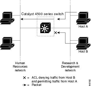
ACLs permit or deny packet forwarding based on how the packet matches the entries in the ACL. For example, you can use access lists to allow one host to access a part of a network, but prevent another host from accessing the same part. In Figure 62-1, ACLs applied at the router input allow Host A to access the Human Resources network, but prevent Host B from accessing the same network.
Figure 62-1 Using ACLs to Control Traffic to a Network
Note![]() Starting IOS XE 3.11.0, Catalyst 4500 series switches do not support egress ACLs on a tunnel interface and on the source interface of the tunnel.
Starting IOS XE 3.11.0, Catalyst 4500 series switches do not support egress ACLs on a tunnel interface and on the source interface of the tunnel.
Port ACLs
You can also apply ACLs to Layer 2 interfaces on a switch. Port ACLs are supported on physical interfaces and EtherChannel interfaces. The following access lists are supported on Layer 2 interfaces:
- Standard IP access lists using source addresses
- Extended IP access lists using source and destination addresses and optional protocol type information
- IPv6 access lists using source and destination addresses and optional protocol type information
- MAC extended access lists using source and destination MAC addresses and optional protocol type information
Note![]() Negative TCP flags such as -syn, -psh or -fin in ACEs are not considered when you apply port ACLs, We recommend that you use positive TCP flags in ACEs.
Negative TCP flags such as -syn, -psh or -fin in ACEs are not considered when you apply port ACLs, We recommend that you use positive TCP flags in ACEs.
As with router ACLs, the switch examines ACLs associated with features configured on a given interface and permits or denies packet forwarding based on how the packet matches the entries in the ACL. In the example in Figure 62-1, if all workstations were in the same VLAN, ACLs applied at the Layer 2 input would allow Host A to access the Human Resources network, but prevent Host B from accessing the same network.
When you apply a port ACL to a trunk port, the ACL filters traffic on all VLANs present on the trunk port. When you apply a port ACL to a port with voice VLAN, the ACL filters traffic on both data and voice VLANs.
With port ACLs, you can filter IP traffic by using IP access lists and non-IP traffic by using MAC addresses. You can filter both IP and non-IP traffic on the same Layer 2 interface by applying both an IP access list and a MAC access list to the interface.
With port ACLs, you can filter IPv4 traffic with IPv4 access lists, IPv6 traffic with IPv6 access lists, and non-IP traffic with MAC access lists. You can filter multiple types of traffic simultaneously by applying ACLs of the appropriate type to the Layer 2 interface simultaneously.
Note![]() You cannot simultaneously apply more than one access list of a given type to a Layer 2 interface. If an IPv4, IPv6, or MAC access list is already configured on a Layer 2 interface, and you apply a new IPv4, IPv6 or MAC access list to the interface, the new ACL replaces the previously configured ACL of the same type.
You cannot simultaneously apply more than one access list of a given type to a Layer 2 interface. If an IPv4, IPv6, or MAC access list is already configured on a Layer 2 interface, and you apply a new IPv4, IPv6 or MAC access list to the interface, the new ACL replaces the previously configured ACL of the same type.
Dynamic ACLs
Various security features, such as 802.1X, NAC and Web Authentication, are capable of downloading ACLs from a central server and applying them to interfaces. Prior to Cisco IOS Release 12.2(54)SG, these features required the explicit configuration of a standard port ACL
Starting with Cisco IOS Release 12.2(54)SG, a port ACL does not require configuration. For more details refer to the “Removing the Requirement for a Port ACL”.
VLAN Maps
VLAN maps can control the access of all traffic in a VLAN. You can apply VLAN maps on the switch to all packet s that are routed into or out of a VLAN or are bridged within a VLAN. VLAN maps are not defined by direction (input or output).
Note![]() Negative TCP flags such as -syn, -psh or -fin in ACEs are not considered when you apply VLAN ACLs, We recommend that you use positive TCP flags in ACEs.
Negative TCP flags such as -syn, -psh or -fin in ACEs are not considered when you apply VLAN ACLs, We recommend that you use positive TCP flags in ACEs.
You can configure VLAN maps to match Layer 3 addresses for IP traffic. Access of all non-IP protocols is controlled with a MAC address and an Ethertype using MAC ACLs in VLAN maps. (IP traffic is not controlled by MAC ACLs in VLAN maps.) You can enforce VLAN maps only on packets heading to the switch; you cannot enforce VLAN maps on traffic between hosts on a hub or on another switch connected to this switch.
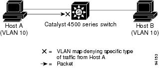
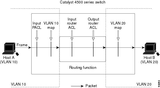
With VLAN maps, forwarding packets is permitted or denied, based on the action specified in the map. Figure 62-2 illustrates how a VLAN map is applied to deny a specific type of traffic from Host A in VLAN 10 from being forwarded.
Figure 62-2 Using VLAN Maps to Control Traffic
Hardware and Software ACL Support
This section describes how to determine whether ACLs are processed in hardware or in software:
- Flows that match a deny statement in standard and extended ACLs are dropped in hardware if ICMP unreachable messages are disabled.
- Flows that match a permit statement in standard ACLs are processed in hardware.
- The following ACL types are not supported in software:
–![]() Standard Xerox Network Systems (XNS) Protocol access list
Standard Xerox Network Systems (XNS) Protocol access list
–![]() Protocol type-code access list
Protocol type-code access list
–![]() Standard Internet Packet Exchange (IPX) access list
Standard Internet Packet Exchange (IPX) access list
Note![]() Packets that require logging are processed in software. A copy of the packets is sent to the CPU for logging while the actual packets are forwarded in hardware so that non-logged packet processing is not impacted.
Packets that require logging are processed in software. A copy of the packets is sent to the CPU for logging while the actual packets are forwarded in hardware so that non-logged packet processing is not impacted.
By default, the Catalyst 4500 series switch sends ICMP unreachable messages when a packet is denied by an access list; these packets are not dropped in hardware but are forwarded to the switch so that it can generate the ICMP unreachable message.
To drop access list denied packets in hardware on the input interface, you must disable ICMP unreachable messages using the no ip unreachables interface configuration command. The
ip unreachables command is enabled by default.
Note![]() Cisco IOS Release 12.2(40)SG does not support disabling IP unreachables on interfaces routing IPv6 traffic.
Cisco IOS Release 12.2(40)SG does not support disabling IP unreachables on interfaces routing IPv6 traffic.
Note![]() If you set the no ip unreachable command on all Layer 3 interfaces, output ACL denied packets do not come to the CPU.
If you set the no ip unreachable command on all Layer 3 interfaces, output ACL denied packets do not come to the CPU.
Troubleshooting High CPU Due to ACLs
Packets that match entries in fully programmed ACLs are processed in hardware.
Packets that match entries in partially programmed ACLs are processed in software using the CPU. This may cause high CPU utilization and packets to be dropped.
CPU spikes and connectivity loss may be observed when an ACL applied to a VLAN interface blocks HSRP management multicast traffic. In this scenario where both HSRP member devices may become Active, the resulting high number of IPv6 Neighbor Discovery packets being lifted to the CPU may cause a spike. To avoid this, ensure that the active and the standby devices in HSRP can communicate. Additionally, do not configure the IPv6 HSRP multicast address in the ACL.
To determine whether packets are being dropped due to high CPU utilization, reference the following:
http://www.cisco.com/en/US/products/hw/switches/ps663/products_tech_note09186a00804cef15.shtml
If the ACL and/or IPSG configuration is partially programmed in hardware, upgrading to
Cisco IOS Release 12.2(31)SGA or later and resizing the TCAM regions may enable the ACLs to be fully programmed.
Note![]() Removal of obsolete TCAM entries can take several CPU process review cycles to complete. This process may cause some packets to be switched in software if the TCAM entry or mask utilization is at or near 100 percent.
Removal of obsolete TCAM entries can take several CPU process review cycles to complete. This process may cause some packets to be switched in software if the TCAM entry or mask utilization is at or near 100 percent.
Selecting Mode of Capturing Control Packets
In some deployments, you might want to bridge control packets in hardware rather than globally capture and forward them in software (at the expense of the CPU). The per-VLAN capture mode feature allows a Catalyst 4500 series switch to capture control packets only on selected VLANs and bridge traffic in hardware on all other VLANs.
When you use per-VLAN capture mode on your switch, it partially disables the global TCAM capture entries internally and attaches feature-specific capture ACLs on those VLANs that are enabled for snooping features. (All IP capture entries, and other non-IP entries are still captured through global TCAM.)
Because this feature controls specific control packets, they are captured only on the VLANs on which the internal ACLs are installed. On all other VLANs, the control traffic is bridged in hardware rather than forwarded to CPU.
The per-VLAN capture mode allows you to apply user-defined ACLs and QoS policers (in hardware) on control packets. You can also subject the aggregate control traffic ingressing the CPU to control plane policing.
When you use per-VLAN capture mode, the following four protocol groups are selectable per-VLAN. The breakdown of protocols intercepted by each group is as follows:
- IGMP Snooping—Cgmp, Ospf, Igmp, RipV2, Pim, 224.0.0.1, 224.0.0.2, 224.0.0.*
- DHCP Snooping—Client to Server, Server to Client, Server to Server
Because some of the groups have multiple overlapping ACEs (for example, 224.0.0.* is present in all the groups except for DHCP Snooping), turning on a certain group will also trigger the interception of some protocols from other groups.
Following are the programming triggers for the four protocol groups per-VLAN:
- IGMP Snooping should be enabled globally on a given VLAN.
- DHCP Snooping should be enabled globally on a given VLAN.
Guidelines and Restrictions
Note![]() Before configuring per-VLAN capture mode, you should examine your configuration to ensure that only the necessary features are enabled on the desired VLANs.
Before configuring per-VLAN capture mode, you should examine your configuration to ensure that only the necessary features are enabled on the desired VLANs.
The following guidelines and restrictions apply to per-VLAN capture mode:
- Starting with Cisco IOS Release 15.0(2)SG on Supervisor Engine 6-E, 6L-E
Starting with Cisco IOS XE Release 3.2.0 on Supervisor Engine 7-E
Starting with Cisco IOS XE Release 3.2.0XO on Supervisor Engine 7L-E
Starting with Cisco IOS XE Release 3.6.0 on Supervisor Engine 8-E
Starting with Cisco IOS XE Release 3.10.0E on Supervisor Engine 9-E
globally reserved static ACL entries in the TCAM region for Layer 3 control packets are removed. The per-VLAN CTI command is not needed and does not apply for Layer 3 control packets because these packets are captured in per-VLAN fashion by default.
–![]() Global static capture and CTI commands for IGMP or PIM packets (both use MAC addresses 224.0.0.1 and 224.0.0.2)
Global static capture and CTI commands for IGMP or PIM packets (both use MAC addresses 224.0.0.1 and 224.0.0.2)
–![]() Global and per-VLAN CTI for DHCP packets
Global and per-VLAN CTI for DHCP packets
With Cisco IOS Release 15.0(2)SG, per-VLAN capture of Layer 3 control packets is driven by SVI configuration. Except for IGMP, PIM, or DHCP, no special configuration is required.
Enabling per-VLAN capture mode consumes additional entries in the ACL/feature TCAM. The number of available TCAM entries depends on the type of supervisor engine. The entry and mask count further limits the utilization of the ACL/feature TCAM.
- On Supervisor Engines IV, V and V-10 GE a maximum of 32 action entries are supported at ingress and 64 entries are supported at egress. To avoid high CPU utilization, move ACEs with a ‘log’ action towards end of the ACL so that the available action index can be used optimally to process other ACE actions.
- Certain configurations can exhaust TCAM resource earlier in per-VLAN capture mode than in global capture mode (such as, when IP Source Guard is enabled on several interfaces or on a user-configured PACL).
You can resize TCAM regions to make more entries available to the PortAndVlan or PortOrVlan region based on the configuration. This allows more entries to be programmed in hardware before reaching the limit. When TCAM resources are exhausted, the packets are forwarded in software.
- In per-VLAN capture mode, you can configure ACLs to permit or deny control traffic on a VLAN or port.
Because security ACLs are terminated by an implicit deny, you must ensure that the ACLs are configured to permit the control packets necessary for the feature (protocol) to operate. However, this rule does not differ from the default behavior.
- CPU spikes and connectivity loss may be observed when an ACL applied to a VLAN interface blocks HSRP management multicast traffic. In this scenario where both HSRP member devices may become Active, the resulting high number of IPv6 Neighbor Discovery packets being lifted to the CPU may cause a spike. To avoid this, ensure that the active and the standby devices in HSRP can communicate. Additionally, do not configure the IPv6 HSRP multicast address in the ACL.
Selecting Control Packet Capture
To select the mode of capturing control packets, perform this task:
This example shows how to configure a Catalyst 4500 series switch to capture control packets only on VLANs where features are enabled:
This example shows how to configure a Catalyst 4500 series switch to capture control packets globally across all VLANs (using static ACL, the default mode):
When the capture mode changes from global to VLAN, the static CAM entries are invalidated. This creates a window during which control packets may pass through a Catalyst 4500 series switch without being intercepted to the CPU. This temporary situation is restored when the new per-VLAN capture entries are programmed in the hardware.
When you configure per-VLAN capture mode, you should examine the show commands for individual features to verify the appropriate behavior. In per-VLAN capture mode, the invalidated static CAM entries will appear as inactive in the output of the show platform hardware acl input entries static command. For example, the hit count for inactive entries will remain frozen because those entries are invalidated and applied per-VLAN where the feature is enabled. The following table lists the CamIndex entry types and the Cam regions.
|
|
|
|
|
|---|---|---|---|
TCAM Programming and ACLs
You apply three types of hardware resources when you program ACLs and ACL-based features: mapping table entries (MTEs), profiles, and TCAM value/mask entries. If any of these resources are exhausted, packets are sent to the CPU for software-based processing.
Note![]() Supervisor Engine 9-E, 8L-E, 8-E, 7-LE, 7-E, 6L-E, and 6-E automatically manage the available resources. Because masks are not shared on the supervisor engines, only one programming algorithm exists. No regions exist so region resizing is not needed.
Supervisor Engine 9-E, 8L-E, 8-E, 7-LE, 7-E, 6L-E, and 6-E automatically manage the available resources. Because masks are not shared on the supervisor engines, only one programming algorithm exists. No regions exist so region resizing is not needed.
If you exhaust resources on the supervisor engine, you should consider reducing the complexity of your configuration.
Note![]() When an interface is in down state, TCAMs are not consumed for RACLs, but are for PACLs.
When an interface is in down state, TCAMs are not consumed for RACLs, but are for PACLs.
Note![]() TCAM resources are replicated or shared based on the feature combinations applied on the interfaces. For example, if the same ACL and flow monitor configurations are applied on two different interfaces, TCAM resources are shared between the two interfaces. But if multicast routing is added on any one of the interfaces, then TCAM resources are replicated and not shared.
TCAM resources are replicated or shared based on the feature combinations applied on the interfaces. For example, if the same ACL and flow monitor configurations are applied on two different interfaces, TCAM resources are shared between the two interfaces. But if multicast routing is added on any one of the interfaces, then TCAM resources are replicated and not shared.
Layer 4 Operators in ACLs
The following sections provide guidelines and restrictions for configuring ACLs that include Layer 4 port operations:
- Restrictions for Layer 4 Operations
- Configuration Guidelines for Layer 4 Operations
- Using ACLs to Filter TCP Flags and How ACL Processing Impacts CPU
Restrictions for Layer 4 Operations
Note![]() Cisco IOS XE Release 3.7.0E and Cisco IOS Release 15.2(3)E do not support the configuration of named ACLs for noncontiguous ports on an ACE.
Cisco IOS XE Release 3.7.0E and Cisco IOS Release 15.2(3)E do not support the configuration of named ACLs for noncontiguous ports on an ACE.
You can specify these operator types, each of which uses one Layer 4 operation in the hardware:
The limits on the number of Layer 4 operations differ for each type of ACL, and can also vary based on other factors: whether an ACL is applied to incoming or outgoing traffic, whether the ACL is a security ACL or is used as a match condition for a QoS policy, and whether IPv6 ACLs are being programmed using the compressed flow label format.
Note![]() The IPv6 compressed flow label format uses the Layer 2 Address Table to compress a portion of the IPv6 source address of each ACE in the ACL. The extra space freed in the flow label can then be used to support more Layer 4 operations. For this compression to be used, the IPv6 ACL cannot contain any ACEs that mask in only a portion of the bottom 48 bits of the source IPv6 address.
The IPv6 compressed flow label format uses the Layer 2 Address Table to compress a portion of the IPv6 source address of each ACE in the ACL. The extra space freed in the flow label can then be used to support more Layer 4 operations. For this compression to be used, the IPv6 ACL cannot contain any ACEs that mask in only a portion of the bottom 48 bits of the source IPv6 address.
Generally, you will receive at most the following number of Layer 4 operations on the same ACL:
Note![]() Where up to 16 operations are supported, the seventeenth will trigger an expansion.
Where up to 16 operations are supported, the seventeenth will trigger an expansion.
If you exceed the number of available Layer 4 operations, each new operation might cause the affected ACE to be translated into multiple ACEs in the hardware. If this translation fails, packets are sent to the CPU for software processing.
When you globally enable the ipv6 multicast-routing and ipv6 routing global configuration commands, a reduced number of Layer 4 operations are available for use in IPv6 ACL or QoS. Additionally, the "eq" operator consumes a Layer 4 Operation if it is used to match a source port.
Configuration Guidelines for Layer 4 Operations
When using Layer 4 operators, consider these guidelines:
- Layer 4 operations are considered different if the operator or operand differ. For example, the following ACL contains three different Layer 4 operations because gt 10 and gt 11 are considered two different Layer 4 operations:
Note![]() The eq operator can be used an unlimited number of times because eq does not use a Layer 4 operation in hardware.
The eq operator can be used an unlimited number of times because eq does not use a Layer 4 operation in hardware.
- Layer 4 operations are considered different if the same operator/operand couple applies once to a source port and once to a destination port, as in the following example:
A more detailed example follows:
Access lists 101 and 102 use the following Layer 4 operations:
–![]() gt 10 permit and gt 10 deny both use the same operation because they are identical and both operate on the destination port.
gt 10 permit and gt 10 deny both use the same operation because they are identical and both operate on the destination port.
- Access list 102 Layer 4 operations: 4
- Total Layer 4 operations: 8 (due to sharing between the two access lists)
–![]() neq6 permit is shared between the two ACLs because they are identical and both operate on the same destination port.
neq6 permit is shared between the two ACLs because they are identical and both operate on the same destination port.
–![]() Layer 4 operation 1 stores gt 10 permit and gt 10 deny from ACL 101
Layer 4 operation 1 stores gt 10 permit and gt 10 deny from ACL 101
–![]() Layer 4 operation 2 stores lt 9 deny from ACL 101
Layer 4 operation 2 stores lt 9 deny from ACL 101
–![]() Layer 4 operation 3 stores gt 11 deny from ACL 101
Layer 4 operation 3 stores gt 11 deny from ACL 101
–![]() Layer 4 operation 4 stores neg 6 permit from ACL 101 and 102
Layer 4 operation 4 stores neg 6 permit from ACL 101 and 102
–![]() Layer 4 operation 5 stores neg 6 deny from ACL 101
Layer 4 operation 5 stores neg 6 deny from ACL 101
–![]() Layer 4 operation 6 stores gt 20 deny from ACL 102
Layer 4 operation 6 stores gt 20 deny from ACL 102
Using ACLs to Filter TCP Flags and How ACL Processing Impacts CPU
You can use IPv4 or IPv6 ACLs to filter TCP flags. You do this by configuring ACEs that make up an access list to allow matching on a flag that is set.
You use a combination of flags on which to filter; these combinations are processed in hardware. Only the following combinations are supported (applicable to IPv4 and IPv6 ACLs) and the flags must be used in the specified combination:
–![]() rst —The reset flag indicates that the receiver should delete the connection without further interaction.
rst —The reset flag indicates that the receiver should delete the connection without further interaction.
–![]() ack —The acknowledge flag indicates that the acknowledgment field of a segment specifies the next sequence number the sender of this segment is expecting to receive.
ack —The acknowledge flag indicates that the acknowledgment field of a segment specifies the next sequence number the sender of this segment is expecting to receive.
–![]() syn —The synchronize flag is used to establish connections.
syn —The synchronize flag is used to establish connections.
–![]() fin — The finish flag is used to clear connections.
fin — The finish flag is used to clear connections.
- psh —The push flag indicates the data in the call should be immediately pushed through to the receiving user.
- urg —The urgent flag indicates that the urgent field is meaningful and must be added to the segment sequence number
Note![]() Match-all is not supported. Match-any is supported only when used in the following combinations of positive flags: "rst and ack" (must be combined), "sync and fin and rst" (must be combined), "psh" and "urg".
Match-all is not supported. Match-any is supported only when used in the following combinations of positive flags: "rst and ack" (must be combined), "sync and fin and rst" (must be combined), "psh" and "urg".
ACL processing can impact the CPU in two ways:
- For some packets, when the hardware runs out of resources, the software must perform the ACL matches:
–![]() The TCP flag combinations rst ack, syn fin rst, urg and psh are processed in hardware. Other TCP flag combinations are supported in software.
The TCP flag combinations rst ack, syn fin rst, urg and psh are processed in hardware. Other TCP flag combinations are supported in software.
–![]() If the total number of Layer 4 operations in an ACL is less than six, you can distribute the operations in any way you choose.
If the total number of Layer 4 operations in an ACL is less than six, you can distribute the operations in any way you choose.
To create an ACL (IPv4 or IPv6) to filter TCP tags, perform the following task:
The following access lists are processed completely in hardware:
Access lists 104 and 105 are identical; established is shorthand for rst and ack.
Access list 101, is processed completely in software:
Because four source and two destination operations exist, access list 106 is processed in hardware:
In the following code, the Layer 4 operations for the third ACE trigger an attempt to translate dst lt 1023 into multiple ACEs in hardware, because three source and three destination operations exist. If the translation attempt fails, the third ACE is processed in software.
Similarly, for access list 103, the third ACE triggers an attempt to translate dst gt 1023 into multiple ACEs in hardware. If the attempt fails, the third ACE is processed in software. Although the operations for source and destination ports look similar, they are considered different Layer 4 operations.
Note![]() Remember that source port lt 80 and destination port lt 80 are considered different operations.
Remember that source port lt 80 and destination port lt 80 are considered different operations.
- Some packets must be sent to the CPU for accounting purposes, but the action is still performed by the hardware. For example, if a packet must be logged, a copy is sent to the CPU for logging, but the forwarding (or dropping) is performed in the hardware. Although logging slows the CPU, it does not affect the forwarding rate. This sequence of events would happen under the following conditions:
–![]() When an output ACL denies a packet
When an output ACL denies a packet
–![]() When an input ACL denies a packet, and on the interface where the ACL is applied,
When an input ACL denies a packet, and on the interface where the ACL is applied,
ip unreachable is enabled (ip unreachable is enabled by default on all the interfaces)
Configuring Unicast MAC Address Filtering
To block all unicast traffic to or from a MAC address in a specified VLAN, perform this task:
This example shows how to block all unicast traffic to or from MAC address 0050.3e8d.6400 in VLAN 12:
Configuring Named MAC Extended ACLs
You can filter non-IPv4, non-IPv6 traffic on a VLAN and on a physical Layer 2 port by using MAC addresses and named MAC extended ACLs. The procedure is similar to that of configuring other extended named ACLs. You can use a number to name the access list, but MAC access list numbers from 700 to 799 are not supported.
Note![]() Named MAC extended ACLs cannot be applied to Layer 3 interfaces.
Named MAC extended ACLs cannot be applied to Layer 3 interfaces.
For more information about the supported non-IP protocols in the mac access-list extended command, refer to the Catalyst 4500 Series Switch Cisco IOS Command Reference.
To create a named MAC extended ACL, perform this task:
This example shows how to create and display an access list named mac1, denying only EtherType DECnet Phase IV traffic, but permitting all other types of traffic:
The following example shows how to enable or disable hardware statistics while configuring ACEs in the access list:
Configuring EtherType Matching
You can classify non-IP traffic based on the EtherType value using the existing MAC access list commands. When you classify non-IP traffic by EtherType, you can apply security ACLs and QoS policies to traffic that carry the same EtherType.
EtherType matching allows you to classify tagged and untagged IP packets based on the EtherType value. Tagged packets present a potential operation problem:
- While single-tagged packets are supported on the access and trunk ports, double-tagged packets are not.
- Single and double-tagged packets are not supported if the port mode is dot1qtunnel.
For more information about the mac access-list extended command, refer to the Catalyst 4500 Series Switch Cisco IOS Command Reference.
To create a named MAC extended ACL, perform this task:
This example shows how to create and display an access list named matching, permitting the 0x8863 and 0x8040 EtherType values:
Configuring Named IPv6 ACLs
Supervisor Engine 9-E, 8L-E, 8-E, 7-LE, 7-E, 6L-E, and 6-E support hardware-based IPv6 ACLs to filter unicast, multicast and broadcast IPv6 traffic on Layer 2 and Layer 3 interfaces. You can only configure such access lists on Layer 3 interfaces that are configured with an IPv6 address.
Beginning with IOS XE 3.7.0, you can employ IPv6 wildcard masking when specifying the Layer 3 address of a IPv6 ACL entry. Scale and performance issues that might be introduced by this feature are captured in the following:
http://www.cisco.com/c/en/us/products/switches/catalyst-4500-series-switches/datasheet-listing.html
The following document covers all security related hardware TCAM resources: “Cisco Catalyst 4500E Supervisor Engine 8-E: Wired and Wireless Convergence Data Sheet” http://www.cisco.com/c/en/us/products/collateral/switches/catalyst-4500-series-switches/data_sheet_c78-728191.html
Note![]() routing-type/mobility-type extension header options in an IPv6 ACL have never been supported, but were previously configurable. As of Release IOS XE 3.4.0SG and IOS 15.1(2)SG, configuration of these options has been removed.
routing-type/mobility-type extension header options in an IPv6 ACL have never been supported, but were previously configurable. As of Release IOS XE 3.4.0SG and IOS 15.1(2)SG, configuration of these options has been removed.
.To create a named IPv6 ACLs, perform this task:
The following example shows how to create and display an IPv6 access list named v6test, denying only one IPv6 traffic with one particular source and destination address, but permitting all other types of IPv6 traffic:
The following example show various ways of configuring ACEs in IPv6 ACL:
Here the permit entry allows all packets that have a source UDP port, and specifies the permit conditions for a destination IPv6 addresses using prefix/ prefix-length:
Here the permit entry allows all packets that have a source TCP port and the IPv6 addresses (that has been specified using a wildcard mask), and allows destination addresses that have IPv6 prefix ::/0.
Here the permit entry allows all packets (source and destination) that have IPv6 prefix ::/0. This is necessary because an implicit deny -all condition is at the end of each IPv6 access list.
To enable hardware statistics, enter the following commands while configuring ACEs in the access list:
Note![]() Hardware statistics is disabled by default.
Hardware statistics is disabled by default.
Applying IPv6 ACLs to Layer 2 and 3 Interface
To apply an IPv6 ACL to a Layer 3 interface, perform the following task:
|
|
|
|
|---|---|---|
|
|
||
|
|
||
|
|
Note![]() IPv6 ACLs are supported on Layer 3 interfaces and on Layer 2 ports using the ipv6 traffic-filter command.
IPv6 ACLs are supported on Layer 3 interfaces and on Layer 2 ports using the ipv6 traffic-filter command.
The following example applies the extended-named IPv6 ACL simple-ipv6-acl to SVI 300 routed ingress traffic:
Note![]() Output IPv6 ACLs with ACE to match on the ICMP option fail on a switch.
Output IPv6 ACLs with ACE to match on the ICMP option fail on a switch.
The following conditions may cause a RACL to malfunction (no workaround):
- ACLs are applied on the output direction of the interface.
- IPv6 ACL contain Ace to match on the ICMP option fields (ICMP Type or ICMP Code).
The following examples of nonfunctioning RACLs:
Configuring VLAN Maps
This section includes these topics:
- VLAN Map Configuration Guidelines
- Creating and Deleting VLAN Maps
- Applying a VLAN Map to a VLAN
- Using VLAN Maps in Your Network
This section describes how to configure VLAN maps, which is the only way to control filtering within a VLAN. VLAN maps have no direction. To filter traffic in a specific direction by using a VLAN map, you need to include an ACL with specific source or destination addresses. If there is a match clause for that type of packet (IP or MAC) in the VLAN map, the default action is to drop the packet if the packet does not match any of the entries within the map. If there is no match clause for that type of packet, the default is to forward the packet.
To create a VLAN map and apply it to one or more VLANs, follow these steps:
Step 1![]() Create the standard or extended IP ACLs or named MAC extended ACLs that you want to apply to the VLAN.
Create the standard or extended IP ACLs or named MAC extended ACLs that you want to apply to the VLAN.
Step 2![]() Enter the vlan access-map global configuration command to create a VLAN ACL map entry.
Enter the vlan access-map global configuration command to create a VLAN ACL map entry.
In access map configuration mode, you have the option to enter an action (forward [the default] or drop) and enter the match command to specify an IP packet or a non-IP packet and to match the packet against one or more ACLs (standard or extended). If a match clause is not specified, the action is applied to all packets. The match clause can be used to match against multiple ACLs. If a packet matches any of the specified ACLs, the action is applied.
Note![]() If the VLAN map has a match clause for the type of packet (IP or MAC) and the packet does not match the type, the default is to drop the packet. If there is no match clause in the VLAN map for that type of packet, and no action specified, the packet is forwarded.
If the VLAN map has a match clause for the type of packet (IP or MAC) and the packet does not match the type, the default is to drop the packet. If there is no match clause in the VLAN map for that type of packet, and no action specified, the packet is forwarded.
Step 3![]() Use the vlan filter global configuration command to apply a VLAN map to one or more VLANs.
Use the vlan filter global configuration command to apply a VLAN map to one or more VLANs.
Note![]() You cannot apply a VLAN map to a VLAN on a switch that has ACLs applied to Layer 2 interfaces (port ACLs).
You cannot apply a VLAN map to a VLAN on a switch that has ACLs applied to Layer 2 interfaces (port ACLs).
VLAN Map Configuration Guidelines
When configuring VLAN maps, consider these guidelines:
- VLAN maps do not filter IPv4 ARP packets.
- If there is no router ACL configured to deny traffic on a routed VLAN interface (input or output), and no VLAN map configured, all traffic is permitted.
- Each VLAN map consists of a series of entries. The order of entries in a VLAN map is important. A packet that comes into the switch is tested against the first entry in the VLAN map. If it matches, the action specified for that part of the VLAN map is taken. If there is no match, the packet is tested against the next entry in the map.
- If the VLAN map has at least one match clause for the type of packet (IP or MAC) and the packet does not match any of these match clauses, the default is to drop the packet. If there is no match clause for that type of packet in the VLAN map, the default is to forward the packet.
- The system might take longer to boot if you have configured a very large number of ACLs.
Creating and Deleting VLAN Maps
Each VLAN map consists of an ordered series of entries. To create, add to, or delete a VLAN map entry, perform this task:
You can use the no vlan access-map name global configuration command to delete a map. You can use the no vlan access-map name number global configuration command to delete a single sequence entry from within the map. You can use the no action access-map configuration command to enforce the default action, which is to forward.
VLAN maps do not use the specific permit or deny keywords. To deny a packet by using VLAN maps, create an ACL that would match the packet, and then set the action to drop. A permit in the ACL is the same as a match. A deny in the ACL means no match.
Examples of ACLs and VLAN Maps
These examples show how to create ACLs and VLAN maps for specific purposes.
Example 1
This example shows how to create an ACL and a VLAN map to deny a packet. In the first map, any packets that match the ip1 ACL (TCP packets) would be dropped. You first create the ip1 ACL to permit any TCP packet and no other packets. Because there is a match clause for IP packets in the VLAN map, the default action is to drop any IP packet that does not match any of the match clauses.
This example shows how to create a VLAN map to permit a packet. ACL ip2 permits UDP packets; and any packets that match the ip2 ACL are forwarded.
In this map, any IP packets that did not match any of the previous ACLs (that is, packets that are not TCP packets or UDP packets) would get dropped.
Example 2
In this example, the VLAN map is configured to drop IP packets and to forward MAC packets by default. By applying standard ACL 101 and the extended named access lists igmp-match and tcp-match, the VLAN map is configured to do the following:
- Forward all UDP packets
- Drop all IGMP packets
- Forward all TCP packets
- Drop all other IP packets
- Forward all non-IP packets
Example 3
In this example, the VLAN map is configured to drop MAC packets and forward IP packets by default. By applying MAC extended access lists, good-hosts and good-protocols, the VLAN map is configured to do the following:
- Forward MAC packets from hosts 0000.0c00.0111 and 0000.0c00.0211
- Forward MAC packets of DECnet or VINES (Virtual Integrated Network Service) protocol-family
- Drop all other non-IP packets
- Forward all IP packets
Example 4
In this example, the VLAN map is configured to drop all packets (IP and non-IP). By applying access lists tcp-match and good-hosts, the VLAN map is configured to do the following:
- Forward all TCP packets
- Forward MAC packets from hosts 0000.0c00.0111 and 0000.0c00.0211
- Drop all other IP packets
- Drop all other MAC packets
Applying a VLAN Map to a VLAN
To apply a VLAN map to one or more VLANs, perform this task:
Note![]() You cannot apply a VLAN map to a VLAN on a switch that has ACLs applied to Layer 2 interfaces (port ACLs).
You cannot apply a VLAN map to a VLAN on a switch that has ACLs applied to Layer 2 interfaces (port ACLs).
This example shows how to apply VLAN map 1 to VLANs 20 through 22:
Using VLAN Maps in Your Network
Figure 62-3 shows a typical wiring closet configuration. Host X and Host Y are in different VLANs, connected to wiring closet switches A and C. Traffic moving from Host X to Host Y is routed by Switch B. Access to traffic moving from Host X to Host Y can be controlled at the entry point of Switch A. In the following configuration, the switch can support a VLAN map and a QoS classification ACL.
Figure 62-3 Wiring Closet Configuration
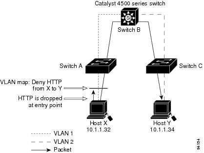
For example, if you do not want HTTP traffic to be switched from Host X to Host Y, you could apply a VLAN map on Switch A to drop all HTTP traffic moving from Host X (IP address 10.1.1.32) to Host Y (IP address 10.1.1.34) at Switch A and not bridge the traffic to Switch B. To configure this scenario, you would do the following.
First, define an IP access list HTTP to permit (match) any TCP traffic on the HTTP port, as follows:
Next, create a VLAN access map named map2 so that traffic that matches the HTTP access list is dropped and all other IP traffic is forwarded, as follows:
You then apply the VLAN access map named map2 to VLAN 1, as follows:
Denying Access to a Server on Another VLAN
Figure 62-4 shows how to restrict access to a server on another VLAN. In this example, server 10.1.1.100 in VLAN 10 has the following access restrictions:
- Hosts in subnet 10.1.2.0/8 in VLAN 20 should not have access.
- Hosts 10.1.1.4 and 10.1.1.8 in VLAN 10 should not have access.
Figure 62-4 Deny Access to a Server on Another VLAN
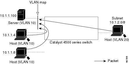
This procedure configures ACLs with VLAN maps to deny access to a server on another VLAN. The VLAN map SERVER 1_ACL denies access to hosts in subnet 10.1.2.0/8, host 10.1.1.4, and host 10.1.1.8. Then it permits all other IP traffic. In Step 3, VLAN map SERVER1 is applied to VLAN 10.
To configure this scenario, follow these steps:
Step 1![]() Define the IP ACL to match and permit the correct packets.
Define the IP ACL to match and permit the correct packets.
Step 2![]() Define a VLAN map using the ACL to drop IP packets that match SERVER1_ACL and forward IP packets that do not match the ACL.
Define a VLAN map using the ACL to drop IP packets that match SERVER1_ACL and forward IP packets that do not match the ACL.
Step 3![]() Apply the VLAN map to VLAN 10.
Apply the VLAN map to VLAN 10.
Displaying VLAN Access Map Information
To display information about VLAN access maps or VLAN filters, perform one of these commands:
it is a sample output of the show vlan access-map command:
Note![]() Sequence 30 does not have a match clause. All packets (IP as well as non-IP) are matched against it and dropped.
Sequence 30 does not have a match clause. All packets (IP as well as non-IP) are matched against it and dropped.
it is a sample output of the show vlan filter command:
Using VLAN Maps with Router ACLs
If the VLAN map has a match clause for a packet type (IP or MAC) and the packet does not match the type, the default is to drop the packet. If there is no match clause in the VLAN map, and no action is specified, the packet is forwarded if it does not match any VLAN map entry.
Note![]() You cannot combine VLAN maps or input router ACLs with port ACLs on a switch.
You cannot combine VLAN maps or input router ACLs with port ACLs on a switch.
- Guidelines for Using Router ACLs and VLAN Maps on the Same VLAN
- Examples of Router ACLs and VLAN Maps Applied to VLANs
Guidelines for Using Router ACLs and VLAN Maps on the Same VLAN
Because the switch hardware performs one lookup for each direction (input and output), you must merge a router ACL and a VLAN map when they are configured on the same VLAN. Merging the router ACL with the VLAN map can significantly increase the number of ACEs.
When possible, try to write the ACL so that all entries have a single action except for the final, default action. You should write the ACL using one of these two forms:
permit...
permit...
permit...
deny ip any any
deny...
deny...
deny...
permit ip any any
To define multiple permit or deny actions in an ACL, group each action type together to reduce the number of entries.
If you need to specify the full-flow mode and the ACL contains both IP ACEs and TCP/UDP/ICMP ACEs with Layer 4 information, put the Layer 4 ACEs at the end of the list. Doing this gives priority to the filtering of traffic based on IP addresses.
Examples of Router ACLs and VLAN Maps Applied to VLANs
These examples show how router ACLs and VLAN maps are applied on a VLAN to control the access of switched, bridged, routed, and multicast packets. Although the following illustrations show packets being forwarded to their destination, each time a packet crosses a line indicating a VLAN map or an ACL, the packet could be dropped rather than forwarded.
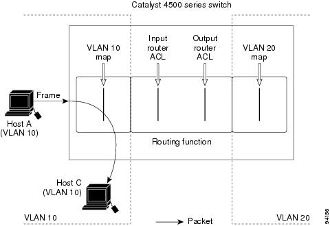
ACLs and Switched Packets
Figure 62-5 shows how an ACL processes packets that are switched within a VLAN. Packets switched within the VLAN are not processed by router ACLs.
Figure 62-5 Applying ACLs on Switched Packets
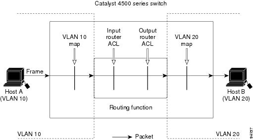
ACLs and Routed Packets
Figure 62-6 shows how ACLs are applied on routed packets. For routed packets, the ACLs are applied in this order:
Figure 62-6 Applying ACLs on Routed Packets
Configuring PACLs
This section describes how to configure PACLs, which are used to control filtering on Layer 2 interfaces. PACLs can filter traffic to or from Layer 2 interfaces based on Layer 3 information, Layer 4 head information or non-IP Layer 2 information.
This section includes these topics:
- Creating a PACL
- PACL Configuration Guidelines
- Removing the Requirement for a Port ACL
- Webauth Fallback
- Configuring IPv4, IPv6, and MAC ACLs on a Layer 2 Interface
- Using PACL with Access-Group Mode
- Configuring Access-group Mode on Layer 2 Interface
- Applying ACLs to a Layer 2 Interface
- Displaying an ACL Configuration on a Layer 2 Interface
Creating a PACL
To create a PACL and apply it to one or more interfaces, follow these steps:
Step 1![]() Create the standard or extended IPv4 ACLs, IPv6 ACLs, or named MAC extended ACLs that you want to apply to the interface.
Create the standard or extended IPv4 ACLs, IPv6 ACLs, or named MAC extended ACLs that you want to apply to the interface.
Step 2![]() Use the IP access-group, IPv6 traffic-filter, or mac access-group interface command to apply IPv4, IPv6, or MAC ACLs to one or more Layer 2 interfaces.
Use the IP access-group, IPv6 traffic-filter, or mac access-group interface command to apply IPv4, IPv6, or MAC ACLs to one or more Layer 2 interfaces.
PACL Configuration Guidelines
When configuring PACLs, consider these guidelines:
- There can be at most one IPv4, one IPv6, and one MAC access list applied to the same Layer 2 interface per direction.
- The IPv4 access list filters only IPv4 packets, the IPv6 access list filters only IPv6 packets, and the MAC access list filters only non-IP packets.
- The number of ACLs and ACEs that can be configured as part of a PACL are bounded by the hardware resources on the switch. Those hardware resources are shared by various ACL features
(for example, RACL, VACL) that are configured on the system. If insufficient hardware resources to program PACL exist in hardware, the actions for input and output PACLs differ:
–![]() For input PACLs, some packets are sent to CPU for software forwarding.
For input PACLs, some packets are sent to CPU for software forwarding.
–![]() For output PACLs, the PACL is disabled on the port.
For output PACLs, the PACL is disabled on the port.
- If insufficient hardware resources exist to program the PACL, the output PACL is not applied to the port, and you receive a warning message.
- The input ACL logging option is supported, although logging is not supported for output ACLs.
- The access group mode can change the way PACLs interact with other ACLs. To maintain consistent behavior across Cisco platforms, use the default access group mode.
- If a PACL is removed when there are active sessions on a port, a hole (permit ip any any) is installed on the port.
Removing the Requirement for a Port ACL
Prior to Cisco IOS Release 12.2(54)SG, a standard port ACL was necessary if you planned to download an ACL from a AAA server. This was because ACL infrastructure was insufficient to provide dynamic creation of access control entries without associating an ACL with the port.
Starting with Cisco IOS Release 12.2(54)SG, configuring a port ACL is not mandatory. If a port ACL is not configured on the port (by entering the ip access-group number in command), a default ACL (AUTH-DEFAULT-ACL) is attached automatically to the port when an ACL is downloaded. It allows only DHCP traffic and consists of the following ACEs:
AUTH-DEFAULT-ACL is automatically created. To modify it, enter the following command:
This ACL is not nvgened. AUTH-DEFAULT-ACL is attached provided there are sessions applying dynamic ACLs (Per-user/Filter-Id/DACL). AUTH-DEFAULT-ACL is removed when the last authenticated session with policies is cleared. It remains attached to the port provided at least one session is applying dynamic policies.
Configuration Restrictions
Debugging Considerations
Syslog messages appear when AUTH-DEFAULT-ACL is attached or detached from an interface provided you enter the epm logging command in configuration mode.
The following syslog displays when the default ACL is attached:
The following syslog displays when the ACL is detached:
Webauth Fallback
Many authentication methods require specific capabilities on the end-point device to respond to the network authenticating device with its identity or credentials. If the end-point lacks the required capability, the authenticator must fallback to alternative methods to gather host or user credentials. If the 802.1X/MAB authentication mechanism fails, a fallback to webauth might occur.
Prior to Cisco IOS Release 12.2(54)SG, webauth fallback implementation required a fallback profile configured on the authenticating device. As part of this profile, an admission rule must be configured along with the access policies (the fallback ACL).
Consider a situation where no port ACL is configured on a port. The first few hosts authenticated through 802.1X/MAB do not download any ACLs. All traffic from these hosts is allowed through. Now, suppose a host connects to the port, and there is a fallback to webauth to authenticate the host. The fallback ACL will be installed on the port, and traffic from previously authenticated hosts will also be restricted by this fallback ACL.
Starting with Cisco IOS Release 12.2(54)SG, Cisco uses a different approach to address this issue. When a host falls back to webauth for authentication, the ACE entries in the fallback ACL are converted into entries with Host IP insertion for a host that has fallen back and will be applied until the host authenticates. Once the host successfully authenticates, the fallback ACL is removed. The resultant host ACLS will be: dynamic ACLs and Port ACL/AUTH-DEFAULT-ACL. Refer to the previous section for an explanation of AUTH-DEFAULT -ACL.
Configuring IPv4, IPv6, and MAC ACLs on a Layer 2 Interface
Note![]() Only IPv4, IPv6 and MAC ACLs can be applied to Layer 2 physical interfaces.
Only IPv4, IPv6 and MAC ACLs can be applied to Layer 2 physical interfaces.
Standard (numbered, named), Extended (numbered, named) IP ACLs, and Extended Named MAC ACLs are also supported.
To apply IPv4 or MAC ACLs on a Layer 2 interface, perform this task:
To apply IPv6 ACLs on a Layer 2 interface, perform this task:
The following example shows how to configure the Extended Named IP ACL simple-ip-acl to permit all TCP traffic and implicitly deny all other IP traffic:
The following example shows how to configure the Extended Named MACL simple-mac-acl to permit source host 000.000.011 to any destination host:
Using PACL with Access-Group Mode
You can use the access group mode to change the way PACLs interact with other ACLs. For example, if a Layer 2 interface belongs to VLAN100, VACL (VLAN filter) V1 is applied on VLAN100, and PACL P1 is applied on the Layer 2 interface. In this situation, you must specify how P1 and V1 impact the traffic with the Layer 2 interface on VLAN100. In a per-interface method, you can use the access-group mode command to specify one of the following desired modes:
- prefer port mode—If PACL is configured on a Layer 2 interface, then PACL takes effect and overwrites the effect of other ACLs (Router ACL and VACL). If no PACL feature is configured on the Layer 2 interface, other features applicable to the interface are merged and applied on the interface. it is the default access group mode.
- prefer VLAN mode—VLAN-based ACL features take effect on the port if they have been applied on the port and no PACLs are in effect. If no VLAN-based ACL features are applicable to the Layer 2 interface, then the PACL feature already on the interface is applied.
- merge mode—Merges applicable ACL features before they are programmed into the hardware.
Configuring Access-group Mode on Layer 2 Interface
To configure an access mode on a Layer 2 interface, perform this task:
This example shows how to merge and apply features other than PACL on the interface:
This example shows how to merge applicable ACL features before they are programmed into hardware:
Applying ACLs to a Layer 2 Interface
To apply IPv4, IPv6, and MAC ACLs to a Layer 2 interface, perform one of these tasks:
|
|
|
|---|---|
|
|
|
|
|
|
|
|
This example applies the extended named IP ACL simple-ip-acl to interface FastEthernet 6/1 ingress traffic:
This example applies the IPv6 ACL simple-ipv6-acl to interface FastEthernet 6/1 ingress traffic:
This example applies the extended named MAC ACL simple-mac-acl to interface FastEthernet 6/1 egress traffic:
Displaying an ACL Configuration on a Layer 2 Interface
To display information about an ACL configuration on Layer 2 interfaces, perform one of these tasks:
|
|
|
|---|---|
|
|
|
|
|
|
|
|
This example shows that the IP access group simple-ip-acl is configured on the inbound direction of interface fa6/1:
This example shows that MAC access group simple-mac-acl is configured on the inbound direction of interface fa6/1:
This example shows that access group merge is configured on interface fa6/1:
Using PACL with VLAN Maps and Router ACLs
For PACLs, the interaction with Router ACLs and VACLs depends on the interface access group mode as shown in Table 62-1 .
|
|
|
||
|---|---|---|---|
PACL, VACL, Input Router ACL (merged) applied in order (ingress) |
|||
Each ACL type listed in Table 62-1 corresponds with these scenarios:
Scenario 1: Host A is connected to an interface in VLAN 20, which has an SVI configured. The interface has input PACL configured, and the SVI has input Router ACL configured as shown in Figure 62-7:
Figure 62-7 Scenario 1: PACL Interaction with an Input Router ACL
If the interface access group mode is prefer port, then only the input PACL is applied on the ingress traffic from Host A. If the mode is prefer VLAN, then only the input Router ACL is applied to ingress traffic from Host A that requires routing. If the mode is merge, then the input PACL is first applied to the ingress traffic from Host A, and the input Router ACL is applied on the traffic that requires routing.
Scenario 2: Host A is connected to an interface in VLAN 10, which has a VACL (VLAN Map) configured and an input PACL configured as shown in Figure 62-8:
Figure 62-8 Scenario 2: PACL Interaction with a VACL
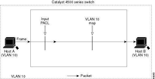
If the interface access group mode is prefer port, then only the input PACL is applied on the ingress traffic from Host A. If the mode is prefer VLAN, then only the VACL is applied to the ingress traffic from Host A. If the mode is merge, the input PACL is first applied to the ingress traffic from Host A, and the VACL is applied on the traffic.
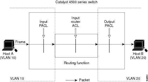
Scenario 3: Host A is connected to an interface in VLAN 10, which has a VACL and an SVI configured. The SVI has an input Router ACL configured and the interface has an input PACL configured, as shown in Figure 62-9:
Figure 62-9 Scenario 3: VACL and Input Router ACL
If the interface access group mode is prefer port, then only the input PACL is applied on the ingress traffic from Host A. If the mode is prefer VLAN, then the merged results of the VACL and the input Router ACL are applied to the ingress traffic from Host A. If the mode is merge, the input PACL is first applied to the ingress traffic from Host A, the VACL is applied on the traffic and finally, and the input Router ACL is applied to the traffic that needs routing. (that is, the merged results of the input PACL, VACL, and input Router ACL are applied to the traffic).
Configuring Object Group ACLs
Object groups provide an alternative way of dealing with ACLs.
Instead of allowing or disallowing individual IP addresses, protocols, and ports (which are used in conventional ACLs), you can use each ACE to allow or disallow an entire group of users to access a group of servers or services.
Object groups enable you to group ACE entries and add or remove entries while keeping your ACL structure more readable. Object group ACLs (OG ACLs) are especially suited to help you manage large ACLs that require frequent changing. Cisco IOS Firewall benefits from object groups, because they simplify policy creation (for example, group A has access to group A services).
Beginning with Cisco IOS XE Release 3.7.1E, object groups are supported for IPv4 ACLs (IPv4 OG ACLs), and with Cisco IOS XE Release 3.9.2E, for IPv6 ACLs (IPv6 OG ACLs).
The feature is supported only on Cisco Catalyst 4500E Series Switches with Supervisor Engine 9-E, 8-E, 7-LE, and 7-E, and Cisco Catalyst 4500-X Series Switches.
See the following sections for more information:
Overview
All features that use or reference conventional ACLs are compatible with OG ACLs. This feature extends the conventional ACLs to support OG ACLs and also adds new keywords and the source and destination addresses and ports.
To configure OG ACLs, you first create one or more object groups. These can be any combination of network object groups or service object groups. You then create ACEs that apply a policy (such as permit or deny) to those object groups.
A network object group includes the following objects:
A service object group includes the following objects:
- Source and destination protocol ports (such as Telnet or Simple Network Management Protocol [SNMP])
- Internet Control Message Protocol (ICMP) types (such as echo, echo-reply, or host-unreachable)
- Top-level protocols (such as Encapsulating Security Payload [ESP], TCP, or UDP)
- Other service object groups
You can configure an OG ACL multiple times with a source group only, a destination group only, or both source and destination groups.
You can add, delete, or change objects in an object group membership list dynamically (without deleting and redefining the object group), and without redefining the ACL ACE that uses the object group.
When you add a member to a group, delete a member from a group, or modify the policy statements in an ACE that uses an access group, the system updates the ACEs in the TCAM. An ACE that is defined using a group name, is equivalent to multiple ACEs (one applied to each entry in the object group). The system expands the object group ACL ACEs into multiple Cisco IOS ACEs (one ACE for each entry in the group) and populates the ACEs in the TCAM. Therefore, the object group ACL feature reduces the number of entries you need to configure but does not reduce TCAM usage.
You cannot delete an object group that is used within an ACL or a class-based policy language (CPL) policy.
Configuring IPv4 OG ACLs
Guidelines and Restrictions for Configuring IPv4 OG ACLs
- The object groups can be used only in extended named and numbered ACLs.
- IPv4 OG ACLs support only Layer 3 interfaces (such as routed interfaces and VLAN interfaces). They do not support Layer 2 features such as VLAN ACLs (VACLs) or port ACLs (PACLs).
- IPv4 OG ACLs are not supported with IPsec.
- IPv4 OG ACLs are not supported on management interfaces, such as FastEthernet1, and on GRE tunnels.
- The maximum number of object group-based ACEs supported in an ACL is 2048.
- IPv4 OG ACEs are used only while processing hardware-switched packets.
ACL statements using object groups are ignored on those packets that are sent to the Route Processor, and such ACL statements are not used for filtering. To match such packets, regular ACEs (without object groups) need to be created in the same ACL.
Creating a Network Object Group
To create a network object group, perform this task:
Creating a Service Object Group
Configuring an IPv4 OG ACL
When creating an object group ACL, configure an ACL that references one or more object groups. As with conventional ACLs, you can associate the same access policy with one or more interfaces.
You can define multiple ACEs that reference object groups within the same object group ACL. You can also reuse a specific object group in multiple ACEs. To create an object group ACL, perform the following task:
Applying an IPv4 OG ACL to an Interface
An object group ACL can be used to control traffic on the interface it is applied to. To apply an object group ACL to an interface, perform the following task:
Verifying IPv4 OG ACLs
Enter the show object-group [ object-group-name ] command, to display the configuration in the named or numbered object group (or in all object groups if no name is entered). For example:
Enter the show ip access-list [ access-list-name ] command, to display the contents of the named or numbered access list or object group ACL (or for all access lists and object group ACLs if no name is entered). For example:
Configuring IPv6 OG ACLs
Guidelines and Restrictions for Configuring IPv6 OG ACLs
- IPv6 OG ACLs are supported only on Layer 3 interfaces (such as routed interfaces and VLAN interfaces).
- Only Cisco IOS ACLs are supported. It is not supported with any other features. The reflexive and evaluate keywords are not supported.
- Only named extended Cisco IOS ACLs are supported. Numbered ACLs are not supported. As with regular ACEs, you can associate the same access policy with one or more interfaces.
- Feature interactions for IPv6 OG ACLs are the same as for Cisco IOS ACLs.
- The maximum number of object group-based ACEs supported in an IPv6 OG ACL is 2048.
- IPv6 OG ACEs are used only while processing hardware-switched packets.
ACL statements using object groups are ignored on those packets that are sent to the Route Processor, and such ACL statements are not used for filtering. To match such packets, regular ACEs (without object groups) need to be created in the same ACL.
Creating a IPv6 Address Network Object Group
To create an IPv6 address network object group, perform this task:
Creating an IPv6 Service Object Group
To create an IPv6 service object group, perform this task:
Configuring an IPv6 OG ACL
Applying an IPv6 OG ACL to an Interface
Verifying IPv6 OG ACLs
Enter the show ipv6 access-list [ access-list-name ] command, to display the contents of the named access list or object group ACL (or for all access lists and object group ACLs if no name is entered). For example:
Configuring RA Guard
This section includes these topics:
Introduction
When deploying IPv6 networks, routers are configured to use IPv6 Router Advertisements to convey configuration information to hosts onlink. Router Advertisement is a critical part of the autoconfiguration process. The conveyed information includes the implied default router address obtained from the observed source address of the Router-Advertisement (RA) message. However, in some networks, invalid RAs are observed. This may happen because of misconfigurations or a malicious attacks on the network.
Devices acting as rogue routers may send illegitimate RAs.When using IPv6 within a single Layer 2 network segment, you can enable Layer 2 devices to drop rogue RAs before they reach end-nodes.
Beginning with Cisco IOS Release 54(SG)SG on Supervisor Engine 6-E (and 6L-E); Cisco IOS XE Release 3.3.0SG on Supervisor Engine 7-E; Cisco IOS XE Release 3.2.0XO on Supervisor Engine 7L-E, Cisco IOS XE Release 3.2.0XO on Supervisor Engine 8-E, and Cisco IOS XE Release 3.10.0E on Supervisor Engine 9-E, the Catalyst 4500 Series Switch supports RA Guard. This feature examines incoming Router-Advertisement and Router-Redirect packets and decides whether to switch or block them based solely on information found in the message and in the Layer 2 device configuration.
You can configure RA Guard in two modes (host and router) based on the device connected to the port.
- Host mode—All the Router-Advertisement and Router-Redirect messages are disallowed on the port.
- Router mode—All messages (RA/RS/Redirect) are allowed on the port; only host mode is supported.
You can configure Catalyst 4500 host ports to allow or disallow RA messages. Once a port is configured to disallow the Router-Advertisement and Router-Redirect packets, it filters the content of the received frames on that port and blocks Router-Advertisement or Router-Redirect frames.
When RA Guard is configured on a port, the following packets are dropped in hardware:
- Router-Advertisement packets —IPv6 ICMP packets with ICMP type = 134
- Router-Redirect packets—IPv6 ICMP packets with ICMP type = 137
Router Solicitation packets are sent out on the ports that are configured with RA Guard policy that defines the device role as a router.
Per port RA Guard ACL statistics are supported and displayed when you enter a show ipv6 snooping counters interface command. The statistics output displays the number of packets that have been dropped per port due to the RA Guard.
Note![]() Beginning with Cisco IOS Release 15.0(2)SG, per port RA Guard ACL statistics are supported and displayed when you enter a show ipv6 snooping counters interface command. (Previous to this release, you enter the show ipv6 first-hop counters interface command.)
Beginning with Cisco IOS Release 15.0(2)SG, per port RA Guard ACL statistics are supported and displayed when you enter a show ipv6 snooping counters interface command. (Previous to this release, you enter the show ipv6 first-hop counters interface command.)
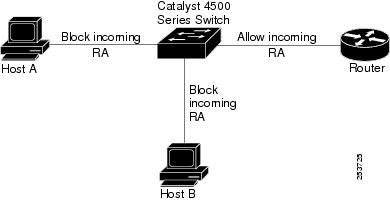
Deployment
Figure 62-10 illustrates a deployment scenario for RA Guard. We drop RA packets from ports that are connected to hosts and permit RA packets from ports connected to the Router.
Figure 62-10 Typical RA Guard Deployment
Configuring RA Guard
To configure RA Guard, perform this step:
Examples
This examples shows how to enable RA Guard on the switch:
The following example shows a sample output of the show ipv6 commands:
Note![]() Beginning with Cisco IOS Release 15.0(2)SG, per port RA Guard ACL statistics are supported and displayed when you enter a show ipv6 snooping counters interface command. (Previous to this release, you enter the show ipv6 first-hop counters interface command.)
Beginning with Cisco IOS Release 15.0(2)SG, per port RA Guard ACL statistics are supported and displayed when you enter a show ipv6 snooping counters interface command. (Previous to this release, you enter the show ipv6 first-hop counters interface command.)
Note![]() Be aware that only RA (Router Advertisement) and REDIR (Router Redirected packets) counters are supported in 12.2(54)SG.
Be aware that only RA (Router Advertisement) and REDIR (Router Redirected packets) counters are supported in 12.2(54)SG.
Note![]() With Cisco Release IOS XE 3.4.0SG and IOS 15.1(2)SG, the show ipv6 nd raguard policy command replaces the show ipv6 first-hop policies command.
With Cisco Release IOS XE 3.4.0SG and IOS 15.1(2)SG, the show ipv6 nd raguard policy command replaces the show ipv6 first-hop policies command.
Usage Guidelines
Observe the following restrictions:
- It is an ingress feature; only IPv6 Router-Advertisement and Router-Redirect packets entering through the port are filtered.
- RA Guard does not offer protection in environments where IPv6 traffic is tunneled.
- Starting with IOS XE 3.4.0SG/15.1(2)SG, RA Guard is supported in software. In prior releases, this Feature is supported only in hardware; packets are not punted to software except under resource exhaustion (for example, TCAM memory exhaustion).
- RA Guard is purely an Layer 2 port based feature and can be configured only on switchports. It works irrespective of whether IPv6 routing is enabled. It is supported on switchports and VLANs.
- RA Guard is supported on trunk ports and VLANs; filtering is performed on packets arriving from all the allowed VLANs.
- Starting with IOS XE 3.4.0SG/15.1(2)SG, RA Guard is not supported on EtherChannel. In prior releases, RA Guard is supported on EtherChannel; the RA Guard configuration (whether present or not) on the EtherChannel overrides the RA Guard configuration on the member ports.
- RA Guard is supported on ports that belong to PVLANs (for example, isolated secondary host ports, community secondary host ports, promiscuous primary host ports, (primary/secondary) trunk ports. Primary VLAN features are inherited and merged with port features.
- Starting with IOS XE 3.4.0SG/15.1(2)SG, RA Guard is supported on Supervisor Engine 8-E, 7-LE, and 7-E, 4500X-32, and 4500X-16 platforms. In prior releases, because of hardware limitations, it may not be possible for Supervisor Engine 6-E, Supervisor Engine 6L-E, Supervisor Engine 7-E and Supervisor Engine 7L-E to collect statistics for RA Guard in hardware. If so, an error message is displayed. Starting with Cisco IOS XE Release 3.10.0E, supported is extended to Supervisor Engine 9-E.
The show ipv6 snooping counter interface command displays the estimated counters.
Note![]() Beginning with Cisco IOS Release 15.0(2)SG, per port RA Guard ACL statistics are supported and displayed when you enter a show ipv6 snooping counters interface command. (Previous to this release, you enter the show ipv6 first-hop counters interface command.)
Beginning with Cisco IOS Release 15.0(2)SG, per port RA Guard ACL statistics are supported and displayed when you enter a show ipv6 snooping counters interface command. (Previous to this release, you enter the show ipv6 first-hop counters interface command.)
 Feedback